Embed Size (px)
Citation preview
Single Arm PantographModel: WBL 85 - Balfour Beatty
Permaquip, SRS
Issue: 1/00 Made available: 25/05/00 Description no.: 4-991B.5111Designed: Techdok Zauner GmbH Checked/approved: Santner
DescriptionMaintenance- andOperating Manual
Contents Single Arm Pantograph WBL 85 Balfour Beatty
Contents
Page 2 WBL 85-15kV
1. Introduction ........................................................................................ 4
2. Safety Instructions ............................................................................. 52.1 General ...................................................................................... 52.2 Carrying Out Earth ..................................................................... 5
2.2.1 Safety Device ............................................................... 52.2.2 Safety Check ................................................................ 52.2.3 Repair and Maintenance Work ..................................... 62.2.4 Transport ...................................................................... 6
3. Technical Data .....................................................................................7
4. Description of Pantograph Components ................................ 8 to 114.1 General Information ................................................................... 84.2 Structural Components ...................................................... 9 to 11
4.2.1 Base Frame .................................................................. 94.2.2. Lower Frame ................................................................ 94.2.3 Upper Frame ................................................................ 94.2.4 Coupling Rod ................................................................ 94.2.5 Pan Head ................................................................ 9, 104.2.6 Parallel Guide Bar ...................................................... 104.2.7 Air Bellow Drive .......................................................... 104.2.8 Electrical Equipment ................................................... 104.2.9 Pneumatic Control Unit ............................................... 104.2.10 Compressed Air Chamber .......................................... 114.2.11 Compresse Air Signal Horn ........................................ 114.2.12 Ltach ........................................................................... 11
5. Assembly ................................................................................. 12 to 135.1 General Information ................................................................. 125.2 Transport .................................................................................. 125.3 Mounting ................................................................................. 125.4 Installation of Electrical Equipment ......................................... 13
5.4.1 High Voltage Connection ............................................ 135.5 Mounting of Pneumatic Air Connection ................................... 13
6. Start - Up ........................................................................................... 146.1 Checklist (also see # 10. “Adjustment“) .................................. 14
7. Maintenance ............................................................................ 15 to 177.1 General Information ................................................................. 157.2 Carbon Current Collector Strip ................................................. 16
ContentsSingle Arm Pantograph WBL 85 Balfour Beatty
7.3 Bearings ................................................................................... 167.3.1 Grooved Ball Bearing, Ball Bearing Guide,
Ball Bushing ................................................................ 167.3.2 Plain Bearing .............................................................. 16
7.4 Screw connections ................................................................... 177.4.1 Fastening Moment for Screw Connections ................. 17
7.5 Bellow Drive ............................................................................. 177.6 Pneumatic Control Unit ............................................................ 17
8. Troubleshooting ...................................................................... 18 to 198.1 General Information ................................................................. 188.2 Trouble Table ................................................................... 18 to 19
9. Repairs ..................................................................................... 20 to 249.1 General Information ................................................................. 209.2 Dismounting of Pantograph from Top of Vehicle Roof ............. 209.3 Complete Disassembly of Pantograph ..................................... 209.4 Repairs of component parts ............................................ 21 to 23
9.4.1 Free Bearing of Base Frame and Upper Frame ......... 219.4.2 Fixed Bearing of Base Frame, Coupling Rod and
Upper Frame .............................................................. 229.4.3 Pan Head .................................................................... 229.4.4 Bellow Drive ................................................................ 239.4.5 Other Component Parts .............................................. 23
9.5 Re-assembly after Complete Disassembly ........................ 23, 24
10. Adjustment Work .................................................................... 24 to 3010.1 General Information ................................................................. 2410.2 Adjustment of Coupling Rod and Resting Position .................. 2510.3 Adjusting the Bellow Drive ....................................................... 2610.4 Adjustment of Contact Pressure .............................................. 2710.5 Adjustment of Raising- and Lowering Time .............................. 2810.6 Adjustment Curve of Contact Pressure .................................... 2910.7 Adjust Turning of Pan Head ..................................................... 3010.8 Adjustment of Pan .................................................................... 3110.9 Adjustment of Contact Force Monitoring System ..................... 32
11. Spare Parts .............................................................................. 33 to 53
12. Annex
Page 3WBL 85-15kV
Introduction Single Arm Pantograph WBL 85 Balfour Beatty
1. Introduction
The single arm pantograph WBL 85 Balfour Beatty has been developed as anearthing pantograph which allows for a mobile electrical earthing of the catenary.Please note that the earthing pantograph should only be used as an additionalearthing between two stationary earthing poles.
Our objective was to design and manufacture a simple, light weight, and easy tomaintain, Pantograph. We further wanted to achieve an optimum in catenary contactbehavior, even under the most basic overhead wire conditions, and combine with it amaximum of operating safety.
The last chapter contains the spare parts drawings. We kindly request you todescribe the needed parts as accurate as possible and in accordance with thiscatalogue to assure a problem free order processing, and subsequent delivery.
Page 4 WBL 85-15kV
Copyright by Schunk Bahntechnik Ges.mbH
All rights reserved.
This publication may not be reproduced, stored in a retrieval system, or transmitted in whole or in part,in any form or by any means, electronic, mechanical, photocopying, recording, or otherwise, withoutthe prior written permission of the Copy Right Owner.
No liability for amy errors in this document.
We reserved the right to make any technical modifications.
Schunk Bahntechnik Ges.mbHAupoint 23A-5101 Bergheim, AUSTRIAphone: (0662) 459200-0fax: (0662) 459200-1email: [email protected]
Safety InstructionsSingle Arm Pantograph WBL 85 Balfour Beatty
2. Safety Instructions
2.1 General
Warning: Earthing with the aid of the WBL 85 earthing pantograph may onlybe carried out by authorsied personnel. For this reason thepantograph can only be activated by a key-switch, which isprovided inside the car.
2.2 Carrying Out Earthing
- Check the overhead wire with a voltage indicator pole.
- Set up fixed earthing points at the ends of the working area in front of andbehind the vehicle (distance of 5-6 km).
- Check again the overhead wire with a voltage indicator pole for correct earthing.
- If the overhead wire is voltage free, raise the pantograph up to the catenary
2.2.1 Safety Device
During raising and lowering of the pantograph, a signal horn sounds. As soon as thepantograph has reached the desired contact pressure for the appropriate earthingfunction, the acoustic signal ceases.
If the contact pressure falls below the preset level, then the signal sounds indicatingthat the earthing function of the pantograph has ceased.
2.2.2 Safety Check
(has be to made everytime from outhorised personnel when panto gets raised):
- Raise pantograph: check that horn sounds
- When carbonstrip contacts the catenary, check that the signal ends
- Wait about 10-15 sec
- Lower pantograph: check that horn sounds
- Raise panto into working position.
Page 5WBL 85-15kV
^ 130 N
Technical Data Single Arm Pantograph WBL 85 Balfour Beatty
Page 6 WBL 85-15kV
2.2.3 Repair and Maintenance Work
Before carrying out any repair and maintenance work ensure that:
- the power to the catenary is switched off
- the pantograph is lowered.
After competing any repair and maintenance work ensure that:
- no tools or other loose parts have been left on the vehicle roof.
2.2.4 Transport
Attention
Persons are not allowed to stay underneath the pantograph duringlifting and transportation.
Technical DataSingle Arm Pantograph WBL 85 Balfour Beatty
Page 7WBL 85-15kV
3. Technical Data
Height in resting position............................................................................454 ±10 mm
Fixation distance - crossways .......................................................................950 ±1 mm
Fixation distance longitudinal ........................................................................800 ±1 mm
Min. working height over resting position ...........................................................100 mm
Max. working height over resting position ........................................................2250 mm
Max. raising height over resting position...................................................2460 ±50 mm
Total length................................................................................................2484 ±10 mm
Lateral deflection at max. working height
and a lateral force of 300 N, according to IEC 494 ..............................................30 mm
Weight ................................................................................................................~120 kg
Contact strip length ............................................................................................920 mm
Pan width ..................................................................................................1600 ±10 mm
Pan height .....................................................................................................300 ±5 mm
Contact strip width................................................................................................35 mm
Contact strip material ..............................................................................Graphit-carbon
Rated voltage .........................................................................................................25 kV
Static contact force...................................................................120 N ±10 N(adjustable)
Rising time to max. working height .............................................................max. 10 sec.
Lowering time from max. working height .....................................................max. 10 sec
Supply pressure from vehicle ..........................................................................min. 5 bar
Electrical resistance of pantograph........................................................................5 mW
Max. speed for earthing function ........................................................................10 km/h
Contact force monitoring:..........................................................................by signal horn
Raising and lowering controlled by ..............................key-switch inside vehicle (provided by vehicle supplier
Description Single Arm Pantograph WBL 85 Balfour Beatty
Page 8 WBL 85-15kV
4. Description of Pantograph Components
4.1 General Information
Main features of the Single Arm Pantograph WBL 85 are:
- Low weight- Simple construction- Minimum maintenance- Excellent contact behavior, even under basic catenary conditions- Maximum operating safety
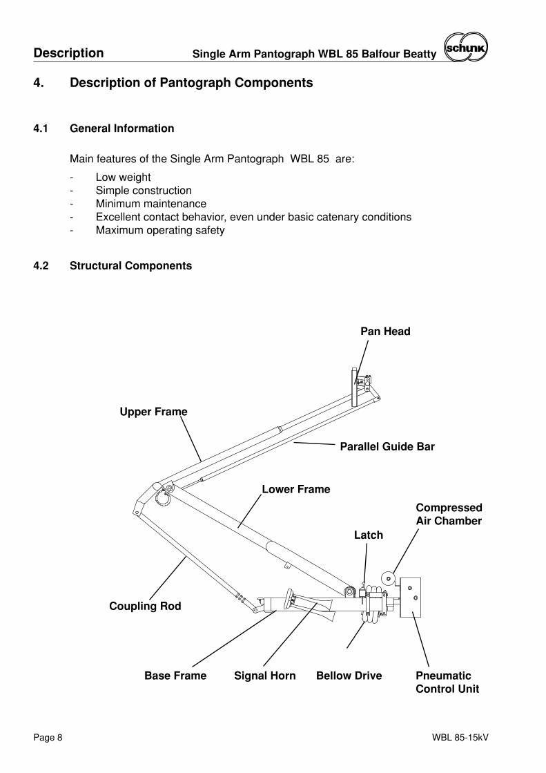
4.2 Structural Components
Bellow Drive
Lower Frame
Upper Frame
Coupling Rod
PneumaticControl Unit
Pan Head
Parallel Guide Bar
Latch
CompressedAir Chamber
Base Frame Signal Horn
DescriptionSingle Arm Pantograph WBL 85 Balfour Beatty
Page 9WBL 85-15kV
4.2.1 Base Frame
The base is a welded structure of closed rectangular hollow steel profiles.
The following component parts are located on the base frame:
- Basic bearings for the lower frame- Resting buffer for upper and lower frame- Mounting fixtures for:
- Air bellow- Coupling rod- High voltage hook-up- Pneumatic control unit- Signal horn
4.2.2. Lower Frame
The lower frame is a welded structure. Its seating is located on the base frame.
The following component parts are mounted to the lower frame:
- Cam disks with suspension fixture for the bellow-drive ropes- Parallel guide bar
4.2.3 Upper Frame
The upper frame is a welded structure made of seamless tubes. Necessary lateralstability is achieved through a cross wire-rope construction.
Attached to the upper frame are the following component parts:
- Pan head- Coupling rod- Lower frame- Bearing blocks for the knuckle joint bearings
4.2.4 Coupling Rod
The coupling rod consists of two individually welded round-tubes. Both tubes arethen connected through a control element. Through this control element thegeometry of the pantograph will be adjusted and fine tuned.
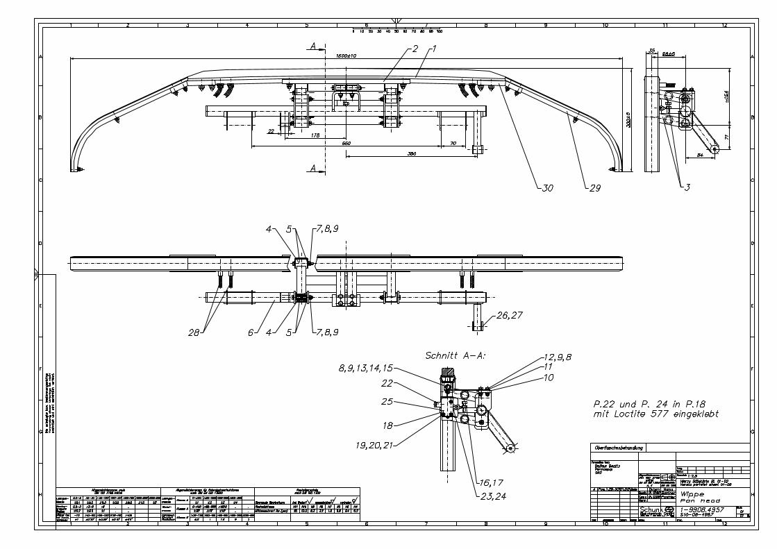
4.2.5 Pan Head
The pan is fixed to the upperframe of the pantograph by means of a pantube. Fitted tothe pan tube are two levers which at the other ends take up the carbon strip via acollectorstrip support. These levers guide the collectorstrip when moving vertically.
WBL 85-15kV
Description Single Arm Pantograph WBL 85 Balfour Beatty
Page 10
The collectorstrip is raised up against weight and contact pressure by means of leafsprings. As the carbon strip presses against the catenary with increasing force, ittensions up until the spring system is arrested by an adjustable stopper.
On the pan, a monitoring valve is located which applies pressure to a pneumaticsignalhorn (located on the baseframe) – as long as the correct contact force betweencarbonstrip and catenary is not reached. When the pre-set contact pressure isachieved, the carbon strip tensions against the stopper, the monitoring valve switchesover, the horn is no longer pressured, and the signal ceases.
In addition, the following parts are located on the pan:
- Shunts for the connection between contact strip and upperframe
- 3/2 way monitoring valve
4.2.6 Parallel Guide Bar
The parallel guide bar prevents the pan head from rotating,. It holds the collector stripin a horizontal position.
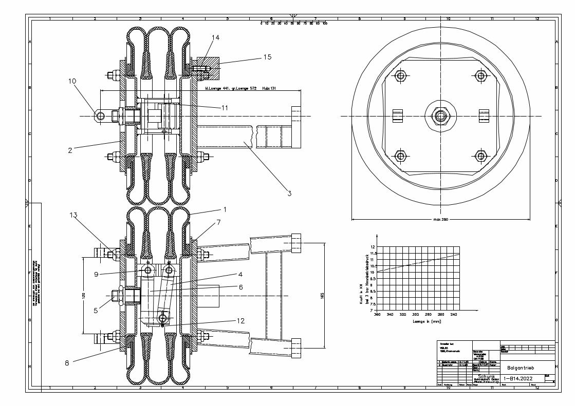
4.2.7 Air Bellow-Drive
The pneumatic bellow drive allows the pantograph to rise. It is mounted between thebase frame and the lower frame. A pneumatic line connects the bellow drive with thevalve control unit. The contact pressure as well as the raising and lowering time isadjusted through the valve control system unit.
4.2.8 Electrical Equipment
All bearing locations are by-passed by shunt connectors. These prevent the currentfrom flowing through the bearings. The shunts are consisting of flexible copper cableswith clamped end pieces. The current connectors are greased with copper grease toarchieve good conducting properties between the shunts and the frame parts.
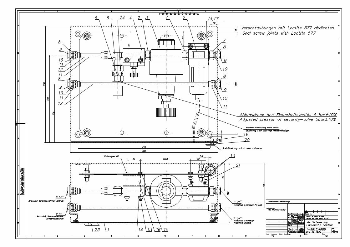
4.2.9 Pneumatic Control Unit
The pneumatic control unit is fitted inside a switching box which is fixed on thebaseframe.
The pneumatic control unit ensures pneumatic adjustment of the pantograph likecontactforce and raising- and loweringtime.
The main components of the valve control unit are:
- Airfilter with condensate seperator
- Pressure regulation valve
- Throttle valve
- Security valve
There is also a pneumatic conduction for the latch, which is leading through theswitchingbox.
4.2.11 Compressed Air Chamber
A compressed air chamber is integrated into the pneumatic feed to the signalhorn,forming a pressure air reservoir, ensuring that – in the event of a fall in air pressure inthe feed to the signal horn (when the pantograph is lowered or when a loss of airpressure occurs in the feed as a result of a fault) – sufficient air volume is stillavailable to enable the signal horn to sound for the appropriate duration.
4.2.12 Compressed Air Signal Horn
A signal horn is attached to the baseframe. The horn sounds during the raising andlowering operations and when there is too little contact pressure onto the catenary. Assoon as the pantograph has reached the required contact pressure for correctearthing function, the acoustic signal ends. A monitoring valve on the pan controls thesignal horn operation.
4.2.13 Latch
The latch ensures, that the pantograph is secured in restingposition, when it is out ofservice. The pneumatic circuit inside the vehicle is layed out in a way, that the latchopens before the the airbellow get under pneumatic-pressure for raising thepantograph.
WBL 85-15kV
DescriptionSingle Arm Pantograph WBL 85 Balfour Beatty
Page 11
WBL 85-15kV
Assembly Single Arm Pantograph WBL 85 Balfour Beatty
Page 12
5. Assembly
5.1 General Information
The Single Arm Pantograph is manufacturer-adjusted according to your system‘srequirements.
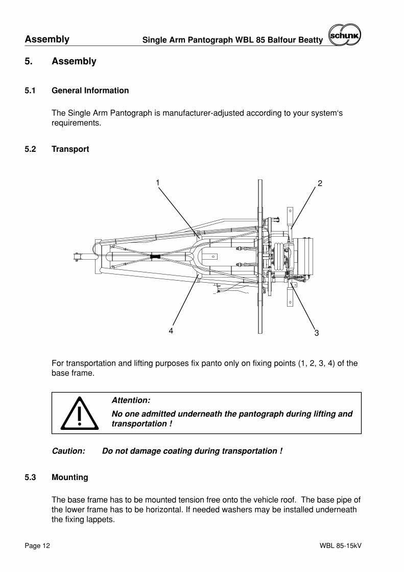
5.2 Transport
For transportation and lifting purposes fix panto only on fixing points (1, 2, 3, 4) of thebase frame.
Attention:
No one admitted underneath the pantograph during lifting andtransportation !
Caution: Do not damage coating during transportation !
5.3 Mounting
The base frame has to be mounted tension free onto the vehicle roof. The base pipe ofthe lower frame has to be horizontal. If needed washers may be installed underneaththe fixing lappets.
1 2
34
5.4 Installation of Electrical Equipment
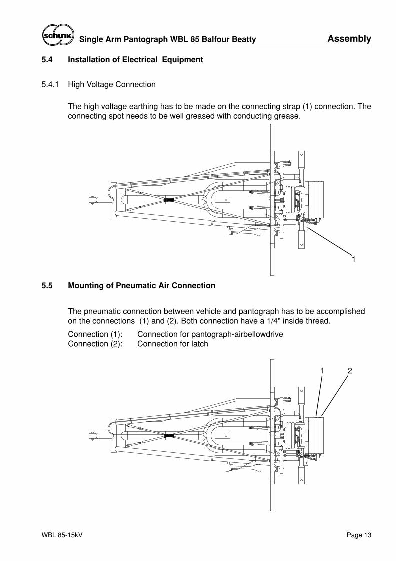
5.4.1 High Voltage Connection
The high voltage earthing has to be made on the connecting strap (1) connection. Theconnecting spot needs to be well greased with conducting grease.
WBL 85-15kV
AssemblySingle Arm Pantograph WBL 85 Balfour Beatty
Page 13
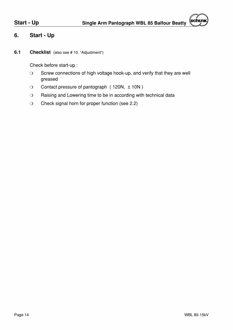
5.5 Mounting of Pneumatic Air Connection
The pneumatic connection between vehicle and pantograph has to be accomplishedon the connections (1) and (2). Both connection have a 1/4" inside thread.
Connection (1): Connection for pantograph-airbellowdriveConnection (2): Connection for latch
21
1
WBL 85-15kV
Start - Up Single Arm Pantograph WBL 85 Balfour Beatty
Page 14
6. Start - Up
6.1 Checklist (also see # 10. “Adjustment“)
Check before start-up :
❍ Screw connections of high voltage hook-up, and verify that they are wellgreased
❍ Contact pressure of pantograph ( 120N, ± 10N )
❍ Raising and Lowering time to be in according with technical data
❍ Check signal horn for proper function (see 2.2)
7. Maintenance
7.1 General Information
The Single Arm Pantograph WBL 85 requires less maintenance. At the regularmaintenance intervals of the vehicles, the following procedures are recommended:
During each inspection (max. 10000 km):
❍ Inspection of carbon strips (breaks, wear).
❍ Inspction of horns.
❍ Check proper function of signalhorn and contact force monitoring system.
Every year:
❍ Visual inspection of screws and shunts.
❍ Visual inspection of cable of raising mechanism, if needed, grease with TOP 2000 of company AGIP Schmiertechnik.
❍ Inspection upward force, adjust, if necessary.
❍ Inspection easy motion of bearings, pan head springs, etc.
❍ Pneumatic equipment for leakages.
After max. 3 years:
❍ Grease the ends of the tow-rope with TOP 2000 of AGIP Schmiertechnik.
❍ Replace shunts.
After every 8 to 10 years and on any main inspection(max. after 2000000 km / 1250000 miles):
❍ Change all ball bearing.
❍ Inspect for corrosion, if necessary replace coaling.
❍ Change rubber bumpers on base frame.
❍ Change leaf springs of pan head.
❍ Change cable of raising mechanism.
❍ Inspect/change of valve control unit.
❍ Change plain bearings.
❍ Replace all air tubes.
❍ Inspect/replace air bellow drive.
❍ Replace 3/2-way monitoring valve on pan head.
WBL 85-15kV
MaintenanceSingle Arm Pantograph WBL 85 Balfour Beatty
Page 15
Maintenance Single Arm Pantograph WBL 85 Balfour Beatty
Page 16 WBL 85-15kV
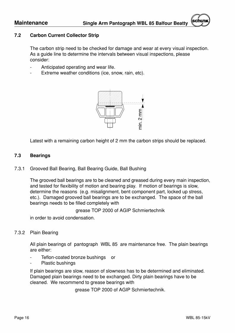
Latest with a remaining carbon height of 2 mm the carbon strips should be replaced.
7.3 Bearings
7.3.1 Grooved Ball Bearing, Ball Bearing Guide, Ball Bushing
The grooved ball bearings are to be cleaned and greased during every main inspection,and tested for flexibility of motion and bearing play. If motion of bearings is slow,determine the reasons (e.g. misalignment, bent component part, locked up stress,etc.). Damaged grooved ball bearings are to be exchanged. The space of the ballbearings needs to be filled completely with
grease TOP 2000 of AGIP Schmiertechnik
in order to avoid condensation.
7.3.2 Plain Bearing
All plain bearings of pantograph WBL 85 are maintenance free. The plain bearingsare either:
- Teflon-coated bronze bushings or- Plastic bushings
If plain bearings are slow, reason of slowness has to be determined and eliminated.Damaged plain bearings need to be exchanged. Dirty plain bearings have to becleaned. We recommend to grease bearings with
grease TOP 2000 of AGIP Schmiertechnik.
min
. 2 m
m
7.2 Carbon Current Collector Strip
The carbon strip need to be checked for damage and wear at every visual inspection.As a guide line to determine the intervals between visual inspections, pleaseconsider:
- Anticipated operating and wear life.- Extreme weather conditions (ice, snow, rain, etc).
MaintenanceSingle Arm Pantograph WBL 85 Balfour Beatty
Page 17WBL 85-15kV
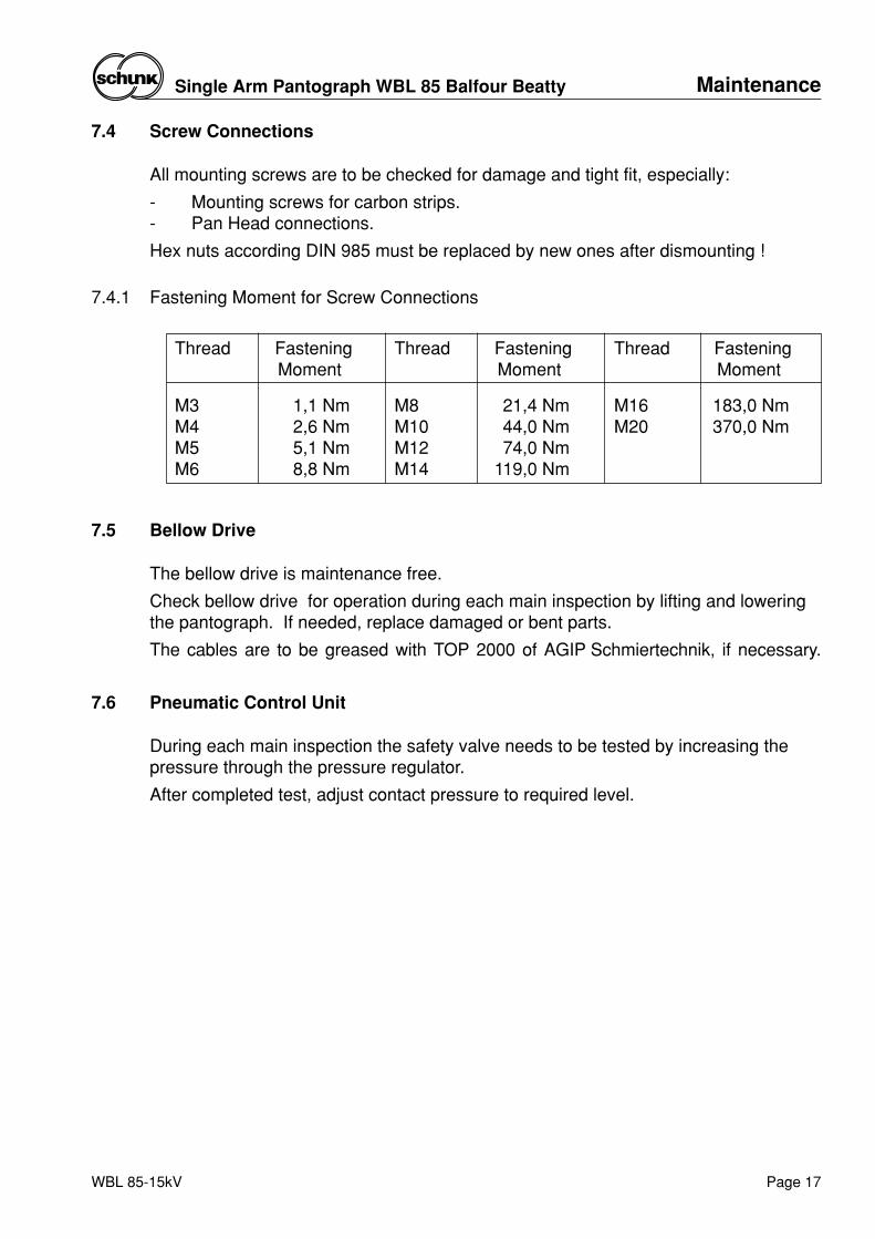
7.4 Screw Connections
All mounting screws are to be checked for damage and tight fit, especially:
- Mounting screws for carbon strips.- Pan Head connections.
Hex nuts according DIN 985 must be replaced by new ones after dismounting !
7.4.1 Fastening Moment for Screw Connections
7.5 Bellow Drive
The bellow drive is maintenance free.
Check bellow drive for operation during each main inspection by lifting and loweringthe pantograph. If needed, replace damaged or bent parts.
The cables are to be greased with TOP 2000 of AGIP Schmiertechnik, if necessary.
7.6 Pneumatic Control Unit
During each main inspection the safety valve needs to be tested by increasing thepressure through the pressure regulator.
After completed test, adjust contact pressure to required level.
Thread FasteningMoment
M3 1,1 NmM4 2,6 NmM5 5,1 NmM6 8,8 Nm
Thread FasteningMoment
M8 21,4 NmM10 44,0 NmM12 74,0 NmM14 119,0 Nm
Thread FasteningMoment
M16 183,0 NmM20 370,0 Nm
Troubleshooting Single Arm Pantograph WBL 85 Balfour Beatty
Page 18 WBL 85-15kV
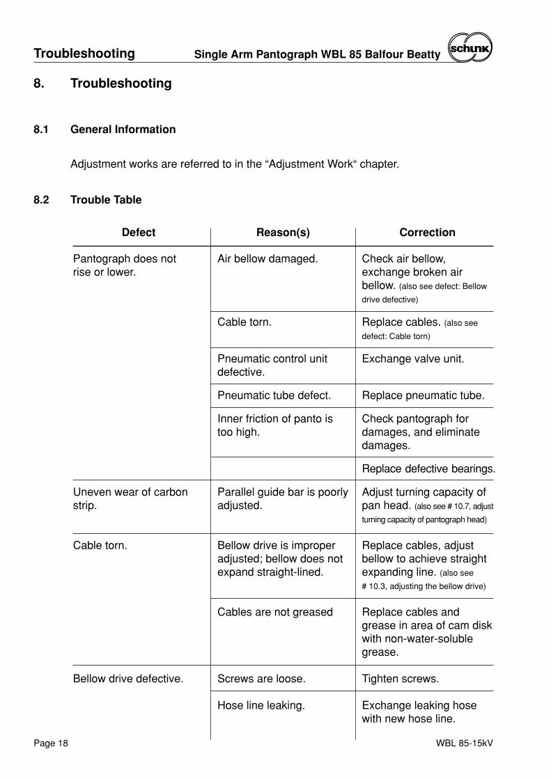
8. Troubleshooting
8.1 General Information
Adjustment works are referred to in the “Adjustment Work“ chapter.
8.2 Trouble Table
Check air bellow,exchange broken airbellow. (also see defect: Bellow
drive defective)
Replace cables. (also see
defect: Cable torn)
Exchange valve unit.
Replace pneumatic tube.
Check pantograph fordamages, and eliminatedamages.
Replace defective bearings.
Adjust turning capacity ofpan head. (also see # 10.7, adjust
turning capacity of pantograph head)
Replace cables, adjustbellow to achieve straightexpanding line. (also see
# 10.3, adjusting the bellow drive)
Replace cables andgrease in area of cam diskwith non-water-solublegrease.
Tighten screws.
Exchange leaking hosewith new hose line.
Air bellow damaged.
Cable torn.
Pneumatic control unitdefective.
Pneumatic tube defect.
Inner friction of panto istoo high.
Parallel guide bar is poorlyadjusted.
Bellow drive is improperadjusted; bellow does notexpand straight-lined.
Cables are not greased
Screws are loose.
Hose line leaking.
Pantograph does not rise or lower.
Uneven wear of carbonstrip.
Cable torn.
Bellow drive defective.
Defect Reason(s) Correction
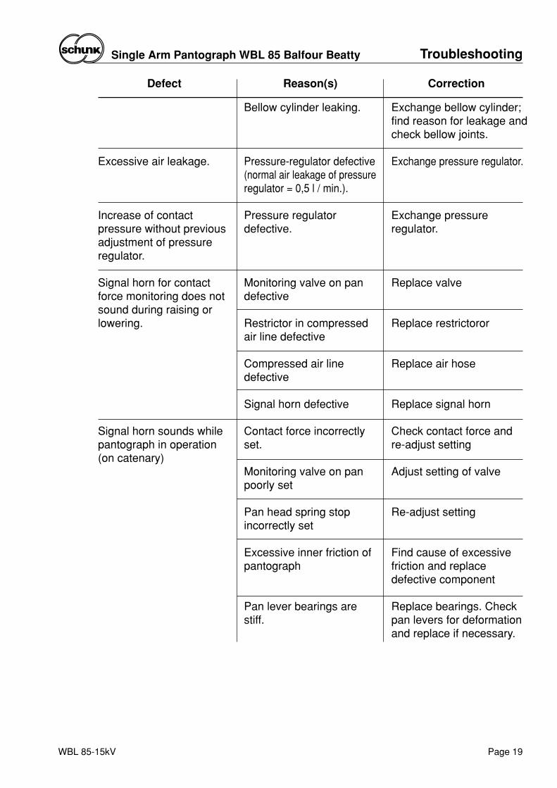
Exchange bellow cylinder;find reason for leakage andcheck bellow joints.
Exchange pressure regulator.
Exchange pressureregulator.
Replace valve
Replace restrictoror
Replace air hose
Replace signal horn
Check contact force andre-adjust setting
Adjust setting of valve
Re-adjust setting
Find cause of excessivefriction and replacedefective component
Replace bearings. Checkpan levers for deformationand replace if necessary.
Bellow cylinder leaking.
Pressure-regulator defective(normal air leakage of pressureregulator = 0,5 l / min.).
Pressure regulatordefective.
Monitoring valve on pandefective
Restrictor in compressedair line defective
Compressed air linedefective
Signal horn defective
Contact force incorrectlyset.
Monitoring valve on panpoorly set
Pan head spring stopincorrectly set
Excessive inner friction ofpantograph
Pan lever bearings arestiff.
Excessive air leakage.
Increase of contactpressure without previousadjustment of pressureregulator.
Signal horn for contactforce monitoring does notsound during raising orlowering.
Signal horn sounds whilepantograph in operation(on catenary)
Defect Reason(s) Correction
TroubleshootingSingle Arm Pantograph WBL 85 Balfour Beatty
Page 19WBL 85-15kV
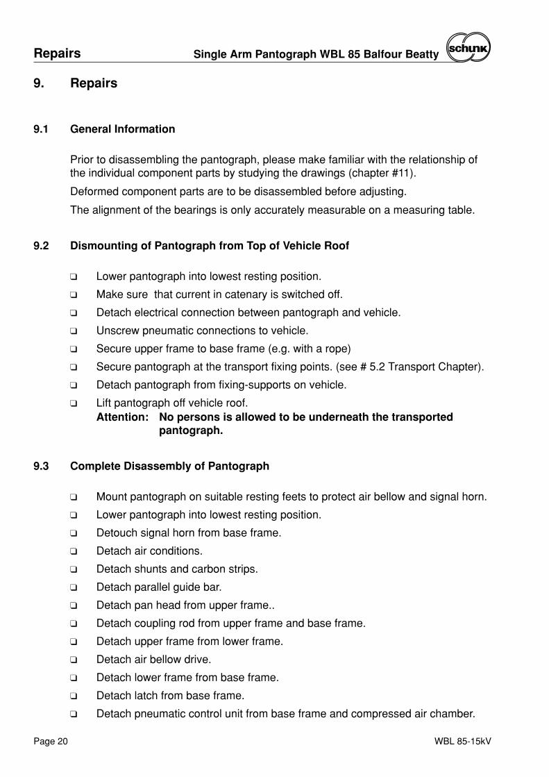
9. Repairs
9.1 General Information
Prior to disassembling the pantograph, please make familiar with the relationship ofthe individual component parts by studying the drawings (chapter #11).
Deformed component parts are to be disassembled before adjusting.
The alignment of the bearings is only accurately measurable on a measuring table.
9.2 Dismounting of Pantograph from Top of Vehicle Roof
❑ Lower pantograph into lowest resting position.
❑ Make sure that current in catenary is switched off.
❑ Detach electrical connection between pantograph and vehicle.
❑ Unscrew pneumatic connections to vehicle.
❑ Secure upper frame to base frame (e.g. with a rope)
❑ Secure pantograph at the transport fixing points. (see # 5.2 Transport Chapter).
❑ Detach pantograph from fixing-supports on vehicle.
❑ Lift pantograph off vehicle roof.Attention: No persons is allowed to be underneath the transported
pantograph.
9.3 Complete Disassembly of Pantograph
❑ Mount pantograph on suitable resting feets to protect air bellow and signal horn.
❑ Lower pantograph into lowest resting position.
❑ Detouch signal horn from base frame.
❑ Detach air conditions.
❑ Detach shunts and carbon strips.
❑ Detach parallel guide bar.
❑ Detach pan head from upper frame..
❑ Detach coupling rod from upper frame and base frame.
❑ Detach upper frame from lower frame.
❑ Detach air bellow drive.
❑ Detach lower frame from base frame.
❑ Detach latch from base frame.
❑ Detach pneumatic control unit from base frame and compressed air chamber.
Repairs Single Arm Pantograph WBL 85 Balfour Beatty
Page 20 WBL 85-15kV
9.4 Repairs of Component Parts
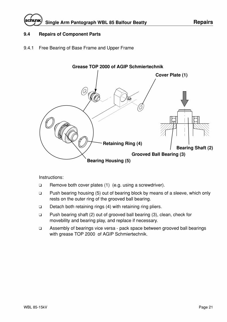
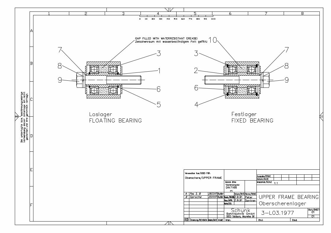
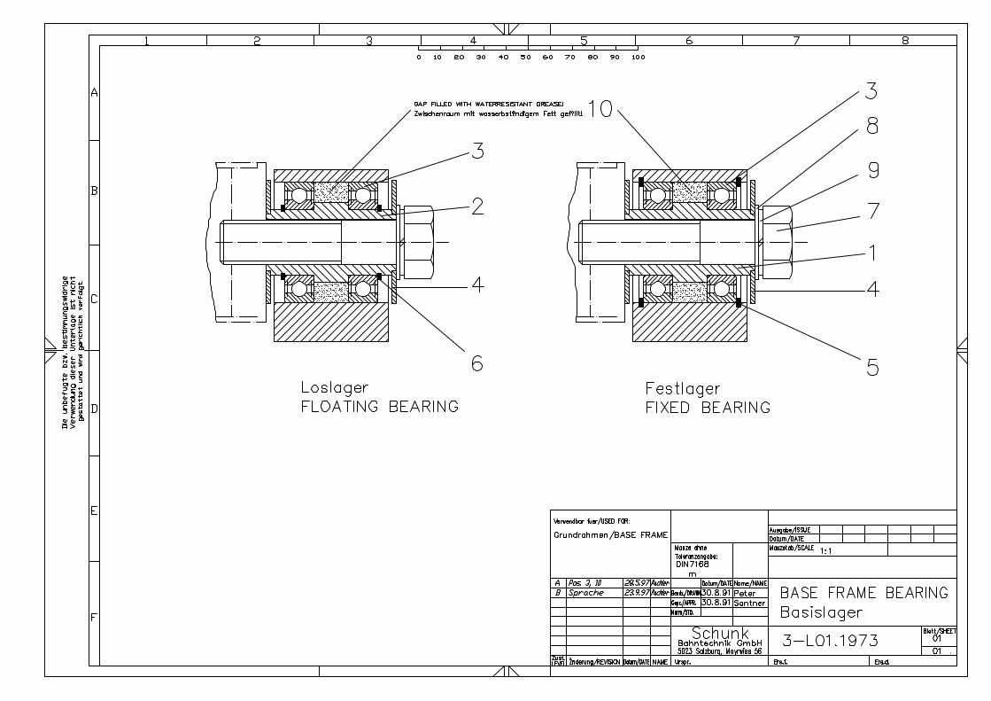
9.4.1 Free Bearing of Base Frame and Upper Frame
Instructions:
❑ Remove both cover plates (1) (e.g. using a screwdriver).
❑ Push bearing housing (5) out of bearing block by means of a sleeve, which onlyrests on the outer ring of the grooved ball bearing.
❑ Detach both retaining rings (4) with retaining ring pliers.
❑ Push bearing shaft (2) out of grooved ball bearing (3), clean, check formovebility and bearing play, and replace if necessary.
❑ Assembly of bearings vice versa - pack space between grooved ball bearingswith grease TOP 2000 of AGIP Schmiertechnik.
Cover Plate (1)
Grease TOP 2000 of AGIP Schmiertechnik
Bearing Housing (5)
Retaining Ring (4)
Grooved Ball Bearing (3)Bearing Shaft (2)
WBL 85-15kV
RepairsSingle Arm Pantograph WBL 85 Balfour Beatty
Page 21
WBL 85-15kV
Repairs Single Arm Pantograph WBL 85 Balfour Beatty
Page 22
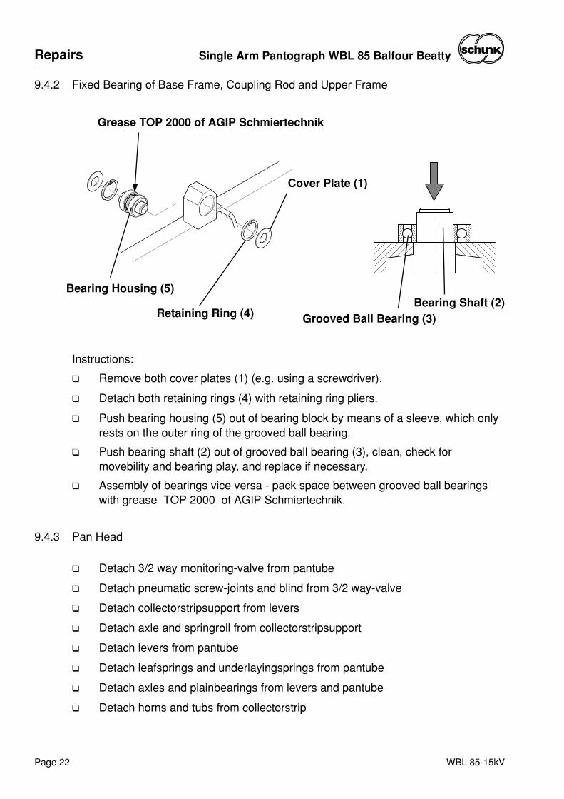
Instructions:
❑ Remove both cover plates (1) (e.g. using a screwdriver).
❑ Detach both retaining rings (4) with retaining ring pliers.
❑ Push bearing housing (5) out of bearing block by means of a sleeve, which onlyrests on the outer ring of the grooved ball bearing.
❑ Push bearing shaft (2) out of grooved ball bearing (3), clean, check formovebility and bearing play, and replace if necessary.
❑ Assembly of bearings vice versa - pack space between grooved ball bearingswith grease TOP 2000 of AGIP Schmiertechnik.
9.4.3 Pan Head
❑ Detach 3/2 way monitoring-valve from pantube
❑ Detach pneumatic screw-joints and blind from 3/2 way-valve
❑ Detach collectorstripsupport from levers
❑ Detach axle and springroll from collectorstripsupport
❑ Detach levers from pantube
❑ Detach leafsprings and underlayingsprings from pantube
❑ Detach axles and plainbearings from levers and pantube
❑ Detach horns and tubs from collectorstrip
9.4.2 Fixed Bearing of Base Frame, Coupling Rod and Upper Frame
Grease TOP 2000 of AGIP Schmiertechnik
Grooved Ball Bearing (3)Bearing Shaft (2)
Cover Plate (1)
Bearing Housing (5)
Retaining Ring (4)
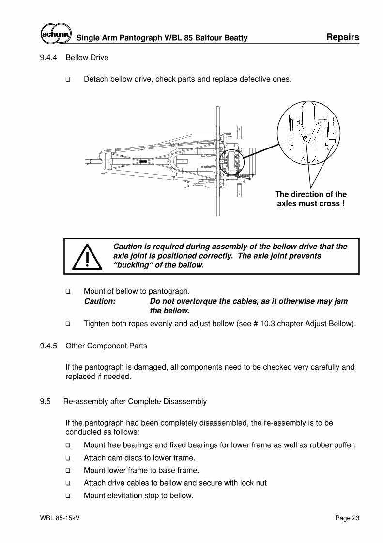
9.4.4 Bellow Drive
❑ Detach bellow drive, check parts and replace defective ones.
Caution is required during assembly of the bellow drive that theaxle joint is positioned correctly. The axle joint prevents“buckling“ of the bellow.
❑ Mount of bellow to pantograph.Caution: Do not overtorque the cables, as it otherwise may jam
the bellow.
❑ Tighten both ropes evenly and adjust bellow (see # 10.3 chapter Adjust Bellow).
9.4.5 Other Component Parts
If the pantograph is damaged, all components need to be checked very carefully andreplaced if needed.
9.5 Re-assembly after Complete Disassembly
If the pantograph had been completely disassembled, the re-assembly is to beconducted as follows:
❑ Mount free bearings and fixed bearings for lower frame as well as rubber puffer.
❑ Attach cam discs to lower frame.
❑ Mount lower frame to base frame.
❑ Attach drive cables to bellow and secure with lock nut
❑ Mount elevitation stop to bellow.
The direction of theaxles must cross !
WBL 85-15kV
RepairsSingle Arm Pantograph WBL 85 Balfour Beatty
Page 23
WBL 85-15kV
Repairs Single Arm Pantograph WBL 85 Balfour Beatty
Page 24
❑ Attach bellow drive to base frame.
❑ Mount drive cables to lower frame and secure with lock nuts.
❑ Assemble coupling rod (bearing, calibration) and mount to base frame.
❑ Install bearings of upper frame.
❑ Mount upper frame to lower frame, and coupling rod to upper frame.
❑ Mount diagonal cables to upper frame and tighten (caution during tightening,upper frame may not distort).
❑ Attach plainbearings and axles into levers.
❑ Mount levers to pantube.
❑ Screw leafsprings and underlayingspring onto pantube.
❑ Mount axle and springroll on collectorstripsupport.
❑ Mount collectorstripsupport on levers.
❑ Attach pneumatic screw connections and blind to 3/2 way-valve.
❑ Screw 3/2-way-monitoring-valve to pantube.
❑ Mount horns and tubs to collectorstrip.
❑ Mount collectorstrip complete with horns on collectorstripsupport.
❑ Attach bearing for parallelguide to pantube.
❑ Mount panhead on upperframe.
❑ Assemble parallel guide bar.
❑ Attach parallel guide bar between lower frame and pan head mount.
❑ Mount latch on base frame.
❑ Mount shunts.
❑ Screw pneumatic control unit to baseframe.
❑ Screw compressed air chamber to baseframe.
❑ Mount signalhorn on baseframe.
❑ Install pneumatic conductions.
❑ Intermediate Check - verify tightness of all screws.
❑ Adjust pantograph (see chapter 10, Adjustment Work).
❑ Final inspection on pantograph.
❑ Mount pantograph to vehicle roof.
❑ Establish electrical connection between pantograph and vehicle.
❑ Establish pneumatic connection from panto to vehicle.
❑ Before operation follow instructions of checklist in chapter 6.1.
Caution: No tools or loose parts may remain on vehicle roof.
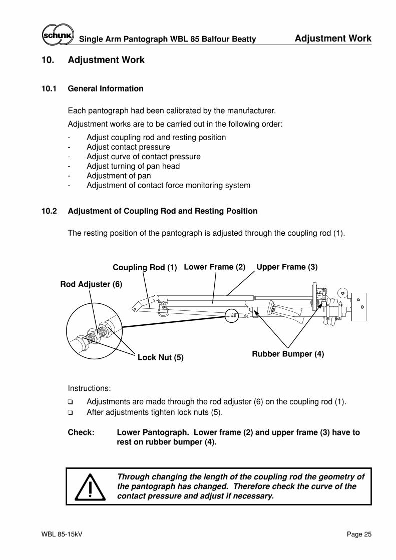
Through changing the length of the coupling rod the geometry ofthe pantograph has changed. Therefore check the curve of thecontact pressure and adjust if necessary.
Rod Adjuster (6)
Lower Frame (2)Coupling Rod (1)
Rubber Bumper (4)Lock Nut (5)
Upper Frame (3)
10. Adjustment Work
10.1 General Information
Each pantograph had been calibrated by the manufacturer.
Adjustment works are to be carried out in the following order:
- Adjust coupling rod and resting position- Adjust contact pressure- Adjust curve of contact pressure- Adjust turning of pan head- Adjustment of pan- Adjustment of contact force monitoring system
10.2 Adjustment of Coupling Rod and Resting Position
The resting position of the pantograph is adjusted through the coupling rod (1).
Instructions:
❑ Adjustments are made through the rod adjuster (6) on the coupling rod (1).❑ After adjustments tighten lock nuts (5).
Check: Lower Pantograph. Lower frame (2) and upper frame (3) have torest on rubber bumper (4).
WBL 85-15kV
Adjustment WorkSingle Arm Pantograph WBL 85 Balfour Beatty
Page 25
WBL 85-15kV
Adjustment Work Single Arm Pantograph WBL 85 Balfour Beatty
Page 26
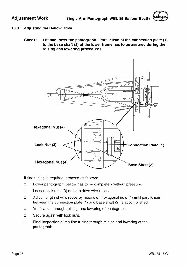
If fine tuning is required, proceed as follows:
❑ Lower pantograph, bellow has to be completely without pressure.
❑ Loosen lock nuts (3) on both drive wire ropes.
❑ Adjust length of wire ropes by means of hexagonal nuts (4) until parallelismbetween the connection plate (1) and base shaft (2) is accomplished.
❑ Verification through raising and lowering of pantograph.
❑ Secure again with lock nuts.
❑ Final inspection of the fine tuning through raising and lowering of thepantograph.
10.3 Adjusting the Bellow Drive
Check: Lift and lower the pantograph. Parallelism of the connection plate (1)to the base shaft (2) of the lower frame has to be assured during theraising and lowering procedures.
Connection Plate (1)
Base Shaft (2)
Lock Nut (3)
Hexagonal Nut (4)
Hexagonal Nut (4)
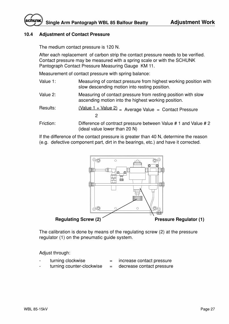
Pressure Regulator (1)Regulating Screw (2)
10.4 Adjustment of Contact Pressure
The medium contact pressure is 120 N.
After each replacement of carbon strip the contact pressure needs to be verified.Contact pressure may be measured with a spring scale or with the SCHUNKPantograph Contact Pressure Measuring Gauge KM 11.
Measurement of contact pressure with spring balance:
Value 1: Measuring of contact pressure from highest working position withslow descending motion into resting position.
Value 2: Measuring of contact pressure from resting position with slowascending motion into the highest working position.
Results: (Value 1 + Value 2)
2
Friction: Difference of contract pressure between Value # 1 and Value # 2(ideal value lower than 20 N)
If the difference of the contact pressure is greater than 40 N, determine the reason(e.g. defective component part, dirt in the bearings, etc.) and have it corrected.
= Average Value = Contact Pressure
The calibration is done by means of the regulating screw (2) at the pressureregulator (1) on the pneumatic guide system.
Adjust through:
- turning clockwise = increase contact pressure- turning counter-clockwise = decrease contact pressure
WBL 85-15kV
Adjustment WorkSingle Arm Pantograph WBL 85 Balfour Beatty
Page 27
Adjustment Work Single Arm Pantograph WBL 85 Balfour Beatty
Page 28 WBL 85-15kV
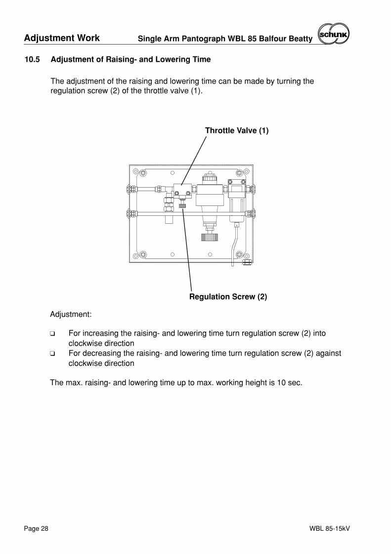
10.5 Adjustment of Raising- and Lowering Time
The adjustment of the raising and lowering time can be made by turning theregulation screw (2) of the throttle valve (1).
Throttle Valve (1)
Regulation Screw (2)
Adjustment:
❑ For increasing the raising- and lowering time turn regulation screw (2) intoclockwise direction
❑ For decreasing the raising- and lowering time turn regulation screw (2) againstclockwise direction
The max. raising- and lowering time up to max. working height is 10 sec.
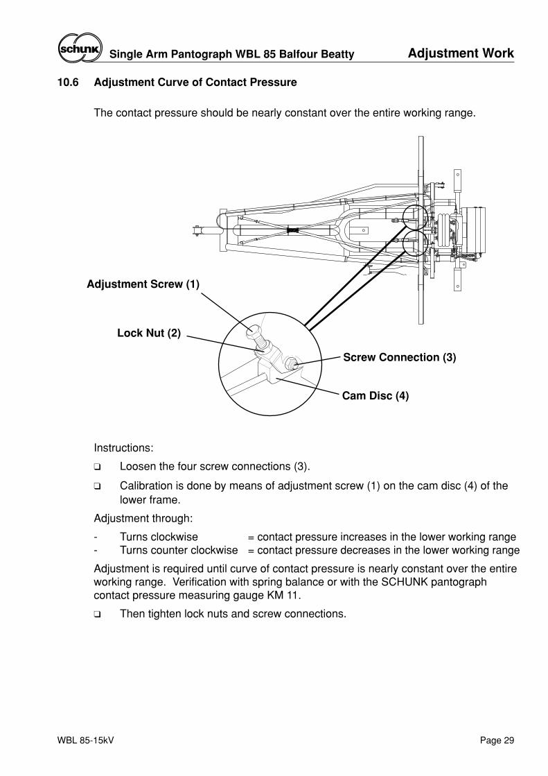
Adjustment Screw (1)
Cam Disc (4)
Lock Nut (2)
Screw Connection (3)
10.6 Adjustment Curve of Contact Pressure
The contact pressure should be nearly constant over the entire working range.
Instructions:
❑ Loosen the four screw connections (3).
❑ Calibration is done by means of adjustment screw (1) on the cam disc (4) of thelower frame.
Adjustment through:
- Turns clockwise = contact pressure increases in the lower working range- Turns counter clockwise = contact pressure decreases in the lower working range
Adjustment is required until curve of contact pressure is nearly constant over the entireworking range. Verification with spring balance or with the SCHUNK pantographcontact pressure measuring gauge KM 11.
❑ Then tighten lock nuts and screw connections.
Adjustment WorkSingle Arm Pantograph WBL 85 Balfour Beatty
Page 29WBL 85-15kV
Adjustment Work Single Arm Pantograph WBL 85 Balfour Beatty
Page 30 WBL 85-15kV
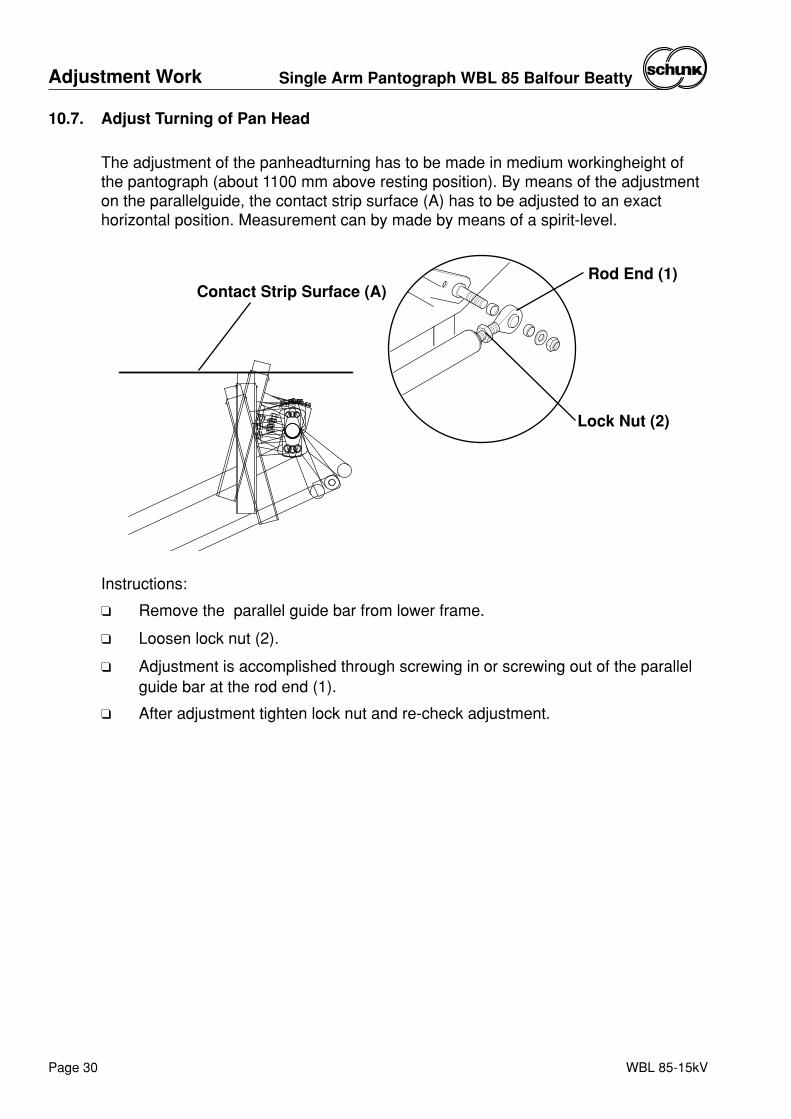
Instructions:
❑ Remove the parallel guide bar from lower frame.
❑ Loosen lock nut (2).
❑ Adjustment is accomplished through screwing in or screwing out of the parallelguide bar at the rod end (1).
❑ After adjustment tighten lock nut and re-check adjustment.
10.7. Adjust Turning of Pan Head
The adjustment of the panheadturning has to be made in medium workingheight ofthe pantograph (about 1100 mm above resting position). By means of the adjustmenton the parallelguide, the contact strip surface (A) has to be adjusted to an exacthorizontal position. Measurement can by made by means of a spirit-level.
Rod End (1)
Lock Nut (2)
Contact Strip Surface (A)
Adjustment WorkSingle Arm Pantograph WBL 85 Balfour Beatty
Page 31WBL 85-15kV
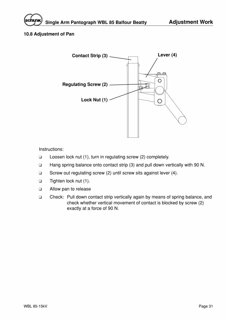
10.8 Adjustment of Pan
Instructions:
❑ Loosen lock nut (1), turn in regulating screw (2) completely.
❑ Hang spring balance onto contact strip (3) and pull down vertically with 90 N.
❑ Screw out regulating screw (2) until screw sits against lever (4).
❑ Tighten lock nut (1).
❑ Allow pan to release
❑ Check: Pull down contact strip vertically again by means of spring balance, and check whether vertical movement of contact is blocked by screw (2) exactly at a force of 90 N.
Lock Nut (1)
Regulating Screw (2)
Contact Strip (3) Lever (4)
Adjustment Work Single Arm Pantograph WBL 85 Balfour Beatty
Page 32 WBL 85-15kV
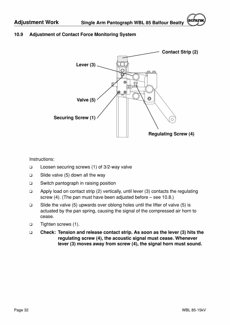
10.9 Adjustment of Contact Force Monitoring System
Instructions:
❑ Loosen securing screws (1) of 3/2-way valve
❑ Slide valve (5) down all the way
❑ Switch pantograph in raising position
❑ Apply load on contact strip (2) vertically, until lever (3) contacts the regulatingscrew (4). (The pan must have been adjusted before – see 10.8.)
❑ Slide the valve (5) upwards over oblong holes until the lifter of valve (5) isactuated by the pan spring, causing the signal of the compressed air horn tocease.
❑ Tighten screws (1).
❑ Check: Tension and release contact strip. As soon as the lever (3) hits the regulating screw (4), the acoustic signal must cease. Whenever lever (3) moves away from screw (4), the signal horn must sound.
Securing Screw (1)
Valve (5)
Lever (3)
Contact Strip (2)
Regulating Screw (4)
Spare PartsSingle Arm Pantograph WBL 85 Balfour Beatty
Page 33WBL 85-15kV
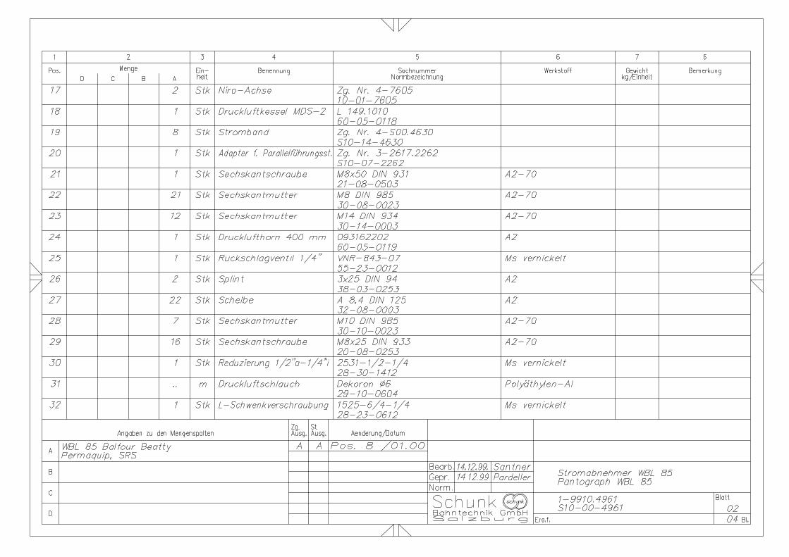
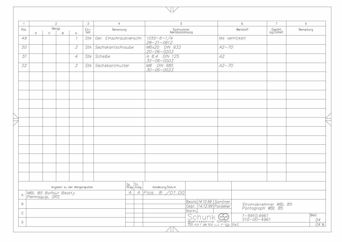
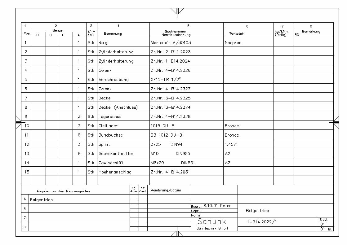
11. Drawings of Component Parts
In your order please specify:
- Type and serial number of pantograph
- Drawing number, item number on drawing, name and number of component part
- Required quantity
The component parts are shown on the following drawings annexed hereto:
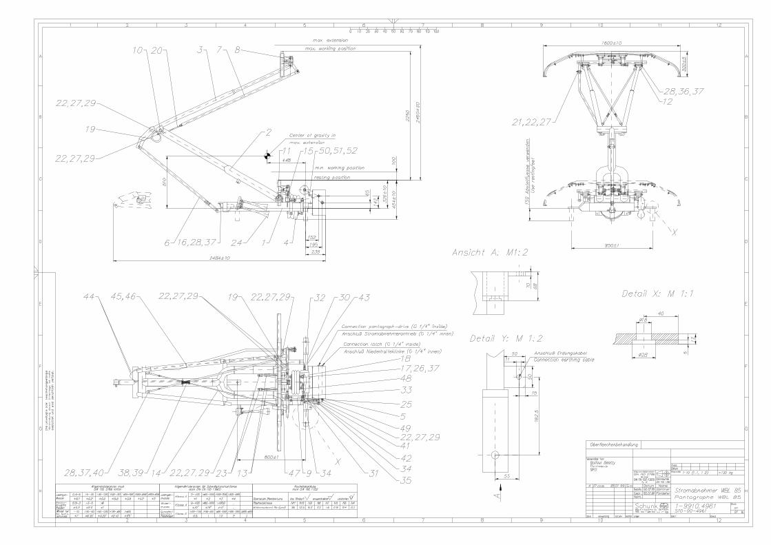
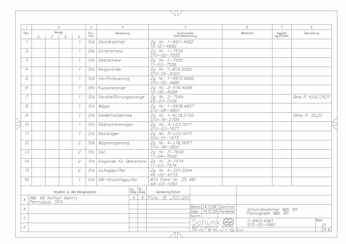
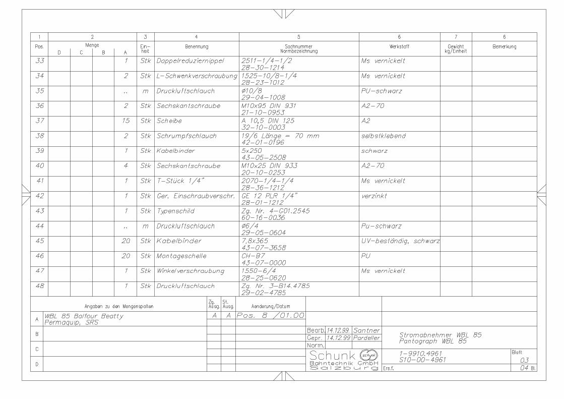
1-9910.4961 ...................................Pantograph WBL 85
1-B14.2022 .....................................Bellow drive
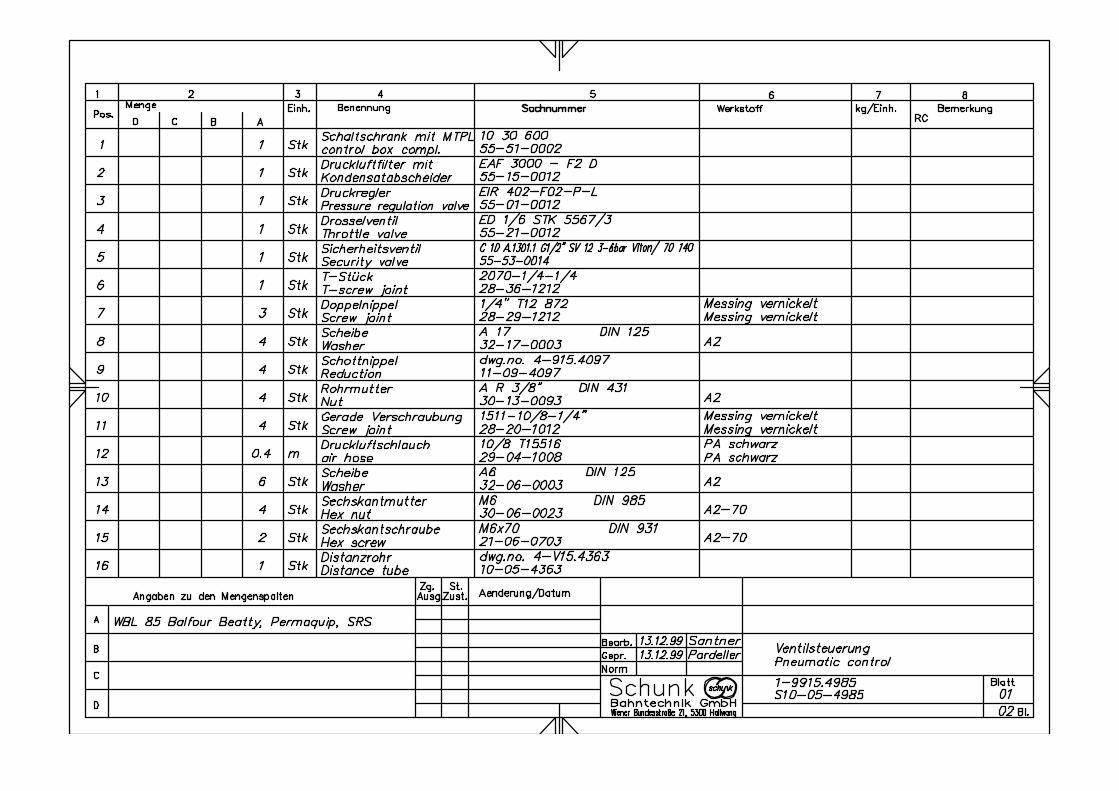
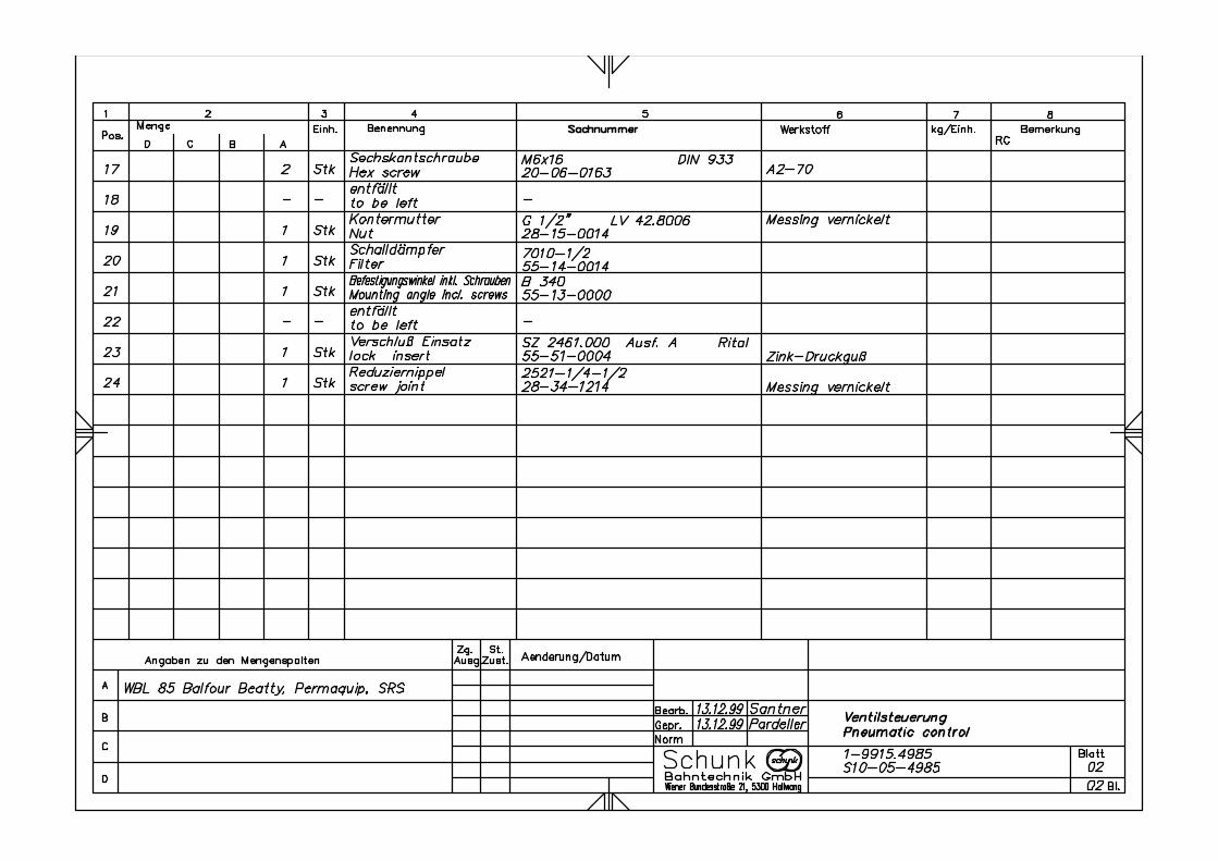
1-9915.4985 ...................................Pneumatic control
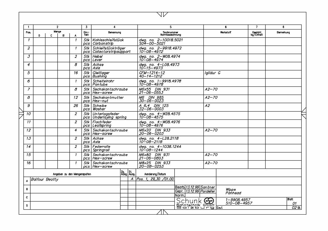
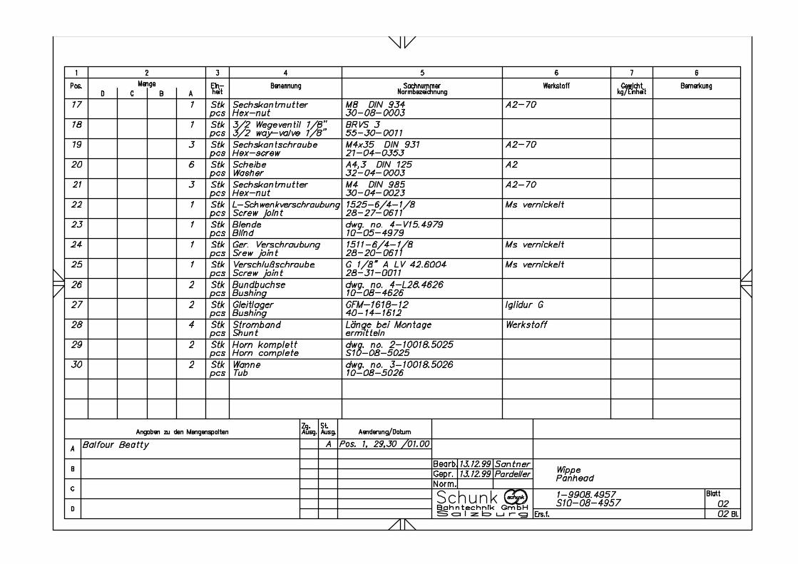
1-9918.4957 ...................................Pan Head
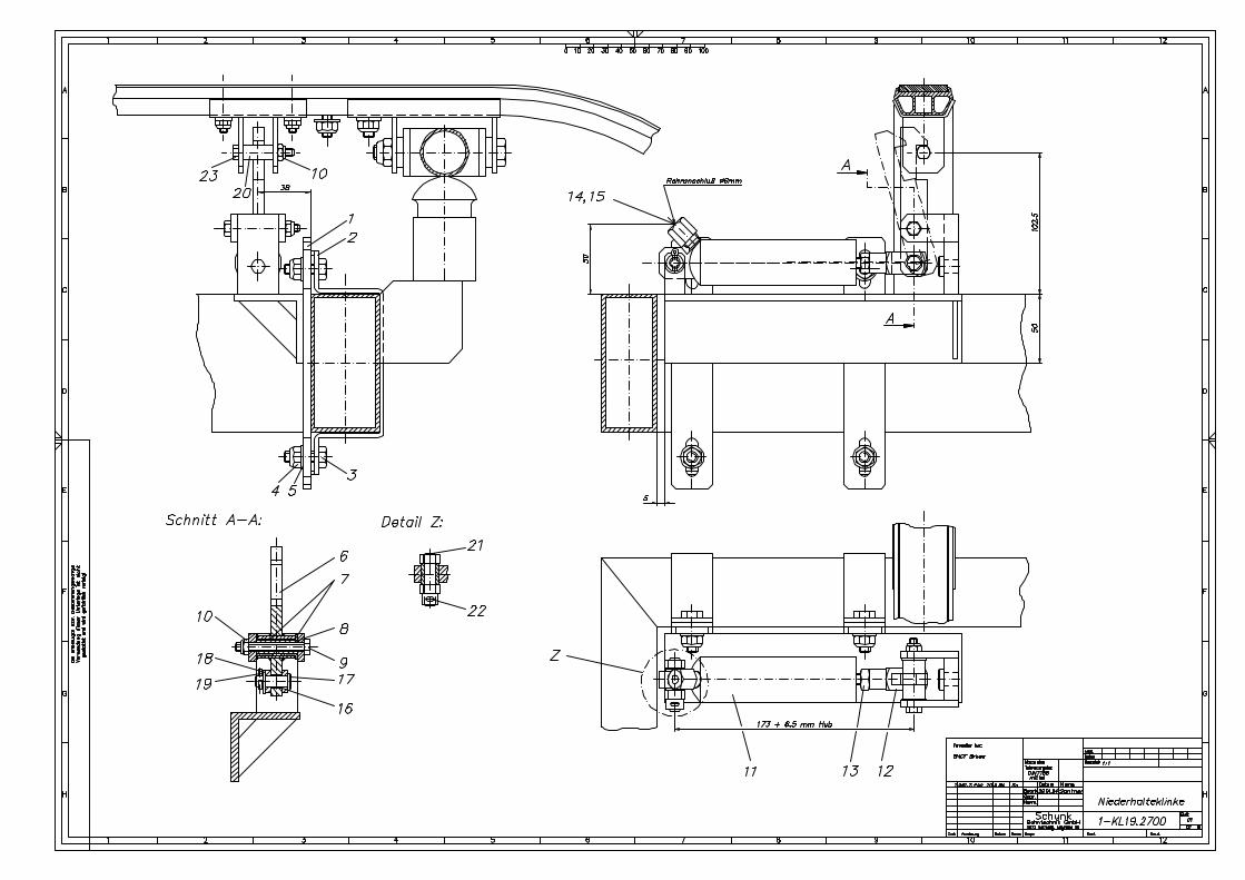
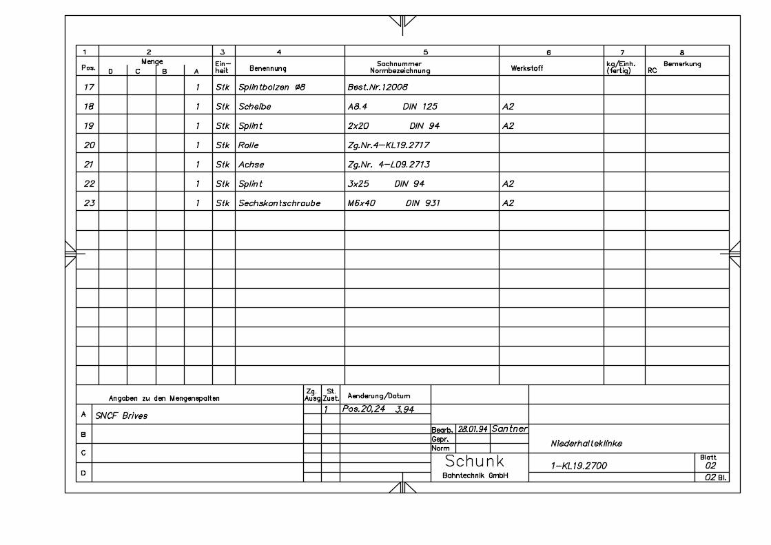
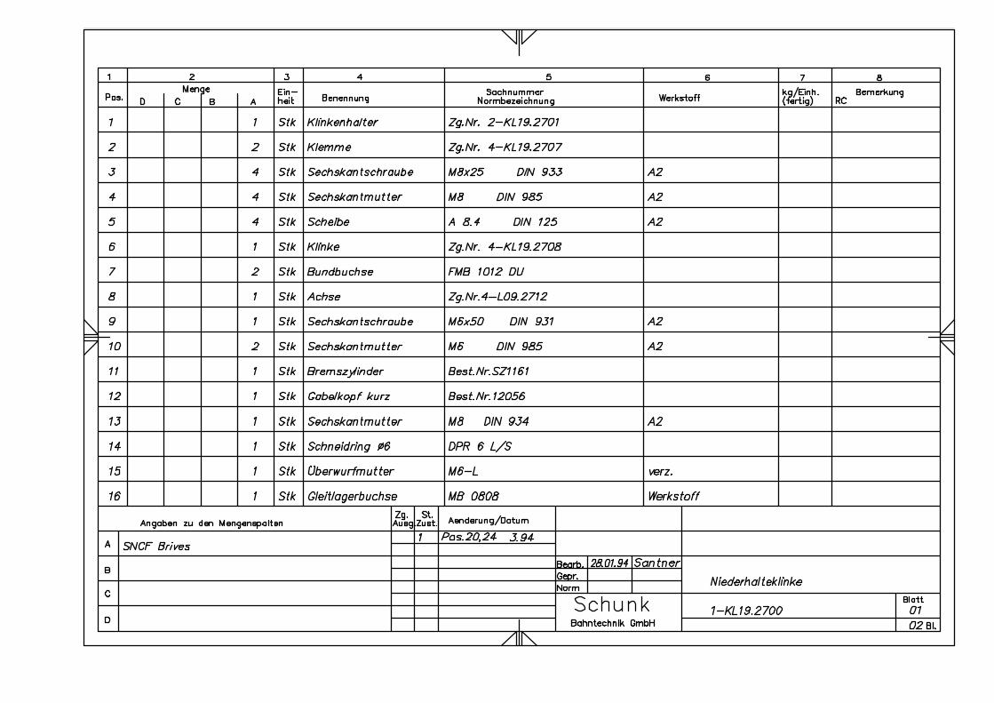
1-KL19.2700 ...................................Latch
3-L03.1977 .....................................Upper frame bearing
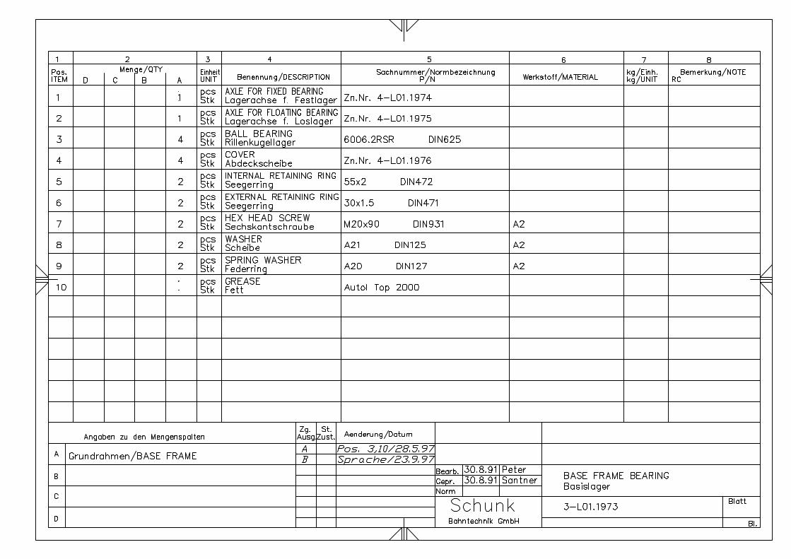
3-L01.1973 .....................................Base frame bearing


AppendixSingle Arm Pantograph WBL 85 Balfour Beatty
Page 55WBL 85-15kV
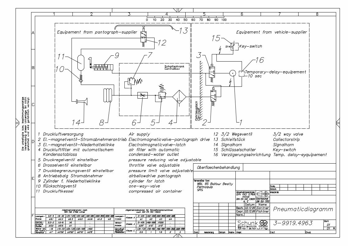
12. Annex
Pneumatic diagramm drawing no. 3-9919.4963