Embed Size (px)
Citation preview

8/8/2019 Single Area OSPF Slides
http://slidepdf.com/reader/full/single-area-ospf-slides 1/84
Ch.2 ± OSPFSingle Area OSPF
CCNA 3 version 3.0
Rick Graziani
Cabrillo College

8/8/2019 Single Area OSPF Slides
http://slidepdf.com/reader/full/single-area-ospf-slides 2/84
Rick Graziani [email protected]
Notes
Configuration of OSPF is easy.
The concepts and theory that make it a robust and scalable protocol isa little more complex.
Information in this presentation that goes beyond that which ispresented in the CCNP 3.0 curriculum.
This information is included to give you a better understanding of OSPF, to answer some of the students¶ questions, and to get an idea
of the true operational features of OSPF.

8/8/2019 Single Area OSPF Slides
http://slidepdf.com/reader/full/single-area-ospf-slides 3/84
Rick Graziani [email protected] 3
Distance Vector Concepts
Pass periodic copies of routing tables to neighbor routers and accumulate distance vector

8/8/2019 Single Area OSPF Slides
http://slidepdf.com/reader/full/single-area-ospf-slides 4/84
Rick Graziani [email protected] 4
Routing loops caused by distance vector

8/8/2019 Single Area OSPF Slides
http://slidepdf.com/reader/full/single-area-ospf-slides 5/84
Rick Graziani [email protected] 5
Distance Vector vs. Link-State
Protocol Examples Characteristics
Distance
Vector
RIP v1 and RIP
v2
Interior Gateway
Routing Protocol
(IGRP)
Copies routing tables to neighbors
Updates frequently
RIP v1 / v2 use hop count as metric
Views the network from the perspective of the neighbors
Slow to converge
Susceptible to routing loopsEasy to configure and administer
Consumes a lot of bandwidth
Link-
state
Open Shortest
Path First (OSPF)
Intermediate-
System to
Intermediate-
System (IS-IS)
Uses shortest path
Updates are event triggered
Sends link-state packets to all network routers
Has common view of network
Fast to converge
Not as susceptible to routing loops
Harder to configure
Requires more memory and processing power than
distance vector
Consumes less bandwidth than distance vector

8/8/2019 Single Area OSPF Slides
http://slidepdf.com/reader/full/single-area-ospf-slides 6/84
Rick Graziani [email protected]
Intr oduction to OSPF Concepts
Introducing OSPF and Link State Concepts
Advantages of OSPF
Brief History
Terminology
Link State Concepts
Introducing the OSPF Routing Protocol
Metric based on Cost (Bandwidth)
Hello
Pr oto
co
l Steps to OSPF Operation
DR/BDR
OSPF Network Types

8/8/2019 Single Area OSPF Slides
http://slidepdf.com/reader/full/single-area-ospf-slides 7/84
Rick Graziani [email protected]
Advantages of OSPF (1 of 2)
OSPF is link-state r outing pr otocol
± RIP, IGRP and EIGRP are distance-vector (routing by rumor)
routing protocols, susceptible to routing loops, split-horizon, and
other issues. OSPF has f ast convergence
± RIP and IGRP hold-down timers can cause slow convergence.
OSPF suppor ts VLSM and CIDR
± RIPv1 and IGRP do not

8/8/2019 Single Area OSPF Slides
http://slidepdf.com/reader/full/single-area-ospf-slides 8/84
Rick Graziani [email protected]
Advantages of OSPF (2 of 2)
Cisco¶s OSPF metric is based on bandwidth
± RIP is based on hop count
± IGRP/EIGRP bandwidth, delay, reliability, load
OSPF only sends out changes when they occur .
± RIP sends entire routing table every 30 seconds, IGRP every 90seconds
± Extra: With OSPF, a router does flood its own LSAs when it agereaches 30 minutes (later)
OSPF also uses the concept of areas to implement hierarchicalr outing
Two open-standard r outing pr otocols to choose f r om:
±RIP, simple but very limited, or
±OSPF, robust but more sophisticated to implement.
IGRP and EIGRP are Cisco pr oprietary

8/8/2019 Single Area OSPF Slides
http://slidepdf.com/reader/full/single-area-ospf-slides 9/84
Rick Graziani [email protected]
Link and Link State
Link: Interface on a router
Link state: Description of an interface and of its relationship to itsneighboring routers, including:
± IP address/mask of the interface,
± The type of network it is connected to
± The routers connected to that network
± The metric (cost) of that link
The collection of all the link-states would form a link-state database.

8/8/2019 Single Area OSPF Slides
http://slidepdf.com/reader/full/single-area-ospf-slides 10/84

8/8/2019 Single Area OSPF Slides
http://slidepdf.com/reader/full/single-area-ospf-slides 11/84
Rick Graziani [email protected]
Area
An area is a collection of networks and routers that has the same area
identification Each router within an area has the same link-state information
All routers will be configured in a single area, the convention is to usearea 0
If OSPF has more than one area, it must have an area 0
Or ³OSPF Routing Domain´
Single Area OSPFuses only one area,usually Area 0

8/8/2019 Single Area OSPF Slides
http://slidepdf.com/reader/full/single-area-ospf-slides 12/84
Rick Graziani [email protected] 12
Cost
Cost is the value assigned to a link Link-state protocols assign a cost to a link, which is based
on the speed of the network connection
Cisco uses a default cost of 108 /bandwidth
10 8 (100,000,000) as the reference bandwidth can bemodified with ospf auto-cost reference-bandwidthcommand
Cisco routers default to T1 (1.544 Mbps) on all serial
interfaces. If a serial link is not a T1 line, use the bandwidthcommand to configure the interface to the right bandwidth
Rtr(config)# inter f ace serial type/port
Rtr(config-if)# bandwidth k bps (Modif y def ault bandwdth)

8/8/2019 Single Area OSPF Slides
http://slidepdf.com/reader/full/single-area-ospf-slides 13/84

8/8/2019 Single Area OSPF Slides
http://slidepdf.com/reader/full/single-area-ospf-slides 14/84
Rick Graziani [email protected]
OSPF¶s Metric is Cost (Bandwidth)
ospf auto-cost reference-bandwidth reference-
bandwidth can be used to modify the reference-bandwidth
for higher speed interfaces
If you use the command ospf auto-costreference-bandwidth reference-bandwidth,
configure all of the routers to use the same value.

8/8/2019 Single Area OSPF Slides
http://slidepdf.com/reader/full/single-area-ospf-slides 15/84
Rick Graziani [email protected] 15
Hello Packets
Each router multicasts hello packets to keep track of the state of theneighbor routers.

8/8/2019 Single Area OSPF Slides
http://slidepdf.com/reader/full/single-area-ospf-slides 16/84
Rick Graziani [email protected] 16
Adjacencies Database (AD)
An AD is a listing of all the neighbors to which a router hasestablished bi-directional communication.
Obtained with the help of Hello packets
Designated Router (DR) A DR is one router on an OSPF multi-access network that
represents all the routers in that network
Backup Designated Router (BDR) A BDR is a standby router that becomes the DR, if the
original DR fails
8/8/2019 Single Area OSPF Slides
http://slidepdf.com/reader/full/single-area-ospf-slides 17/84
Rick Graziani [email protected]
Link State
1 ± Flooding of link-state information
The first thing that happens is that each node, router, on the network
announces its own piece of link-state information to other all other routers on
the network. This includes who their neighboring routers are and the cost of the link between them.
Example: ³Hi, I¶m RouterA, and I can reach RouterB via a T1 link and I can
reach RouterC via an Ethernet link.´
Each router sends these announcements to all of the routers in the network.
1 ± Flooding of link-state
information
8/8/2019 Single Area OSPF Slides
http://slidepdf.com/reader/full/single-area-ospf-slides 18/84
Rick Graziani [email protected]
Link State
2. Building a Topological Database Each router collects all of this link-state information from other routers
and puts it into a topological database.
3. Shor test-Path First (SPF), Dijkstra¶s Algorithm Using this information, the routers can recreate a topology graph of thenetwork.
(Radia Perlman¶s book, I nterconnections, has a very nice example of how to build this graph ± she is one of the contributors to the SPF andSpanning-Tree algorithms.)
1 ± Flooding of link-state
information
2 ± Building a
Topological
Database
3 ± SPF Algorithm

8/8/2019 Single Area OSPF Slides
http://slidepdf.com/reader/full/single-area-ospf-slides 19/84
Rick Graziani [email protected]
Link State
4. Shor test Path First Tree
This algorithm creates an SPF tree, with the router making itself the root of the
tree and the other routers and links to those routers, the various branches.
5. Routing Table
Using this information, the router creates a routing table.
1 ± Flooding of link-
state information
2 ± Building a
Topological
Database
3 ± SPF Algorithm
4 ± SPF Tree
5 ± Routing Table
8/8/2019 Single Area OSPF Slides
http://slidepdf.com/reader/full/single-area-ospf-slides 20/84
Rick Graziani [email protected] 20
Pr oblem: Unsynchr onized Link-State
Adver tisements

8/8/2019 Single Area OSPF Slides
http://slidepdf.com/reader/full/single-area-ospf-slides 21/84
Rick Graziani [email protected] 21
1 ± Flooding of link-state
information
2 ± Building a
Topological
Database
3 ± SPF Algorithm
4 ± SPF Tree
5 ± Routing Table
Link State Concepts
How does the SPF algorithm create an SPF Tree?
Let¶s take a look!
This is extra Information.

8/8/2019 Single Area OSPF Slides
http://slidepdf.com/reader/full/single-area-ospf-slides 22/84
Rick Graziani [email protected] 22
I n order to k eep it simple, we will tak e some liberties with the actual process and algorithm, but y ou will get the basic idea!
You are RouterA and you have exchanged ³Hellos´ with:
± RouterB on your network 11.0.0.0/8 with a cost of 15,
± RouterC on your network 12.0.0.0/8 with a cost of 2
± RouterD on your network 13.0.0.0/8 with a cost of 5 ± Have a ³leaf´ network 10.0.0.0/8 with a cost of 2
This is your link-state information, which you will flood to all other routers.
All other routers will also flood their link state information. (OSPF: only within the
area)
A C
D
2
5
B
1 5
Leaf ́ 10.0.0.0 /8
11.0.0.0 /8
12.0.0.0 /8
13.0.0.0 /8
Extra: Simplif ied Link State Example
2

8/8/2019 Single Area OSPF Slides
http://slidepdf.com/reader/full/single-area-ospf-slides 23/84

8/8/2019 Single Area OSPF Slides
http://slidepdf.com/reader/full/single-area-ospf-slides 24/84
Rick Graziani [email protected] 24
We now get the following link-state information from RouterB: Connected to RouterA on network 11.0.0.0/8, cost of 15
Connected to RouterE on network 15.0.0.0/8, cost of 2
Have a ³leaf´ network 14.0.0.0/8, cost of 15B
Now, Router attaches the two graphs«
C
D
2
5
B
5 2
+ =
.0.0.0 /8
4.0.0.0 /8
5.0.0.0 /8
Link State information f r om RouterB
C
D
2
5
B
5
10.0.0.0 /8
11.0.0.0 /8
12.0.0.0 /8
13.0.0.0 /8
B
1 52
14.0.0.0 /8
15.0.0.0 /8
11.0.0.0
/8
14.0.0.0 /8
15.0.0.0
/8
10.0.0.0 /8 12.0.0.0 /8
13.0.0.0 /8
2
2
2
2
2

8/8/2019 Single Area OSPF Slides
http://slidepdf.com/reader/full/single-area-ospf-slides 25/84
Rick Graziani [email protected] 25
A C
D
2
2
Link State information f r om RouterC
We now get the following link-state information from RouterC:
Connected to RouterA on network 12.0.0.0/8, cost of 2
Connected to RouterD on network 16.0.0.0/8, cost of 2
Have a ³leaf´ network 17.0.0.0/8, cost of 2
12.0.0.0 /8
16.0.0.0 /8
17.0.0.0 /8
2
A C
D
2
5
B
E
1 52
11.0.0.0 /8
14.0.0.0 /8
15.0.0.0 /8
10.0.0.0 /8
12.0.0.0 /8
13.0.0.0 /8
2
2
+
A C
D
2
216.0.0.0 /8
17.0.0.0 /8
2
A C
D
2
5
B
E
1 52
2
=
11.0.0.0 /8
14.0.0.0 /8
15.0.0.0 /8
10.0.0.0 /8 12.0.0.0 /8
13.0.0.0 /8
2
2
17.0.0.0 /8
16.0.0.0 /8
Now, RouterA attaches the two graphs«

8/8/2019 Single Area OSPF Slides
http://slidepdf.com/reader/full/single-area-ospf-slides 26/84
Rick Graziani [email protected] 26
A C
D
5
E
1 02
A C
D
2
5
B
E
1 5
2
1 02
Link State information f r om Router D
We now get the following link-state information from Router D: Connected to RouterA on network 13.0.0.0/8, cost of 5
Connected to RouterC on network 16.0.0.0/8, cost of 2
Connected to RouterE on network 18.0.0.0/8, cost of 2
Have a ³leaf´ network 19.0.0.0/8, cost of 213.0.0.0/8
16.0.0.0/8
18.0.0.0/8
19.0.0.0/8
A C
D
5
E
1 02
18.0.0.0/8
19.0.0.0/8
2
2A C
D
2
5
B
E
1 52
2
11.0.0.0/8
14.0.0.0/8
15.0.0.0/8
12.0.0.0/8
13.0.0.0/8
2
2
17.0.0.0/8
16.0.0.0/8
+
=
11.0.0.0/8
14.0.0.0/8
15.0.0.0/8
12.0.0.0/8
13.0.0.0/8
2
2
17.0.0.0/8
16.0.0.0/8
18.0.0.0/8
19.0.0.0/82
Now, Router A attaches the two graphs«
10.0.0.0/8
10.0.0.0/8

8/8/2019 Single Area OSPF Slides
http://slidepdf.com/reader/full/single-area-ospf-slides 27/84

8/8/2019 Single Area OSPF Slides
http://slidepdf.com/reader/full/single-area-ospf-slides 28/84
Rick Graziani [email protected] 28
Using the topological information we listed, RouterA has now built a complete
topology of the network.
The next step is for the link-state algorithm to find the best path to each node and
leaf network.
A C
D
2
5
B
E
1 52
1 02
2
2
2
22
11.0.0.0 /8
14.0.0.0 /8
12.0.0.0 /8
13.0.0.0 /8
17.0.0.0 /8
16.0.0.0 /8
15.0.0.0 /8
18.0.0.0 /8
20.0.0.0 /8
19.0.0.0 /8
10.0.0.0 /8
Topology

8/8/2019 Single Area OSPF Slides
http://slidepdf.com/reader/full/single-area-ospf-slides 29/84
Rick Graziani [email protected] 29
RouterB: Connected to RouterA on network 11.0.0.0 /8, cost of 15
Connected to RouterE on network 15.0.0.0 /8, cost of 2
Has a ³leaf ́ network 14.0.0.0 /8, cost of 15
RouterC:
Connected to RouterA on network 12.0.0.0 /8, cost of 2
Connected to Router D on network 16.0.0.0 /8, cost of 2
Has a ³leaf ́ network 17.0.0.0 /8, cost of 2
RouterD:
Connected to RouterA on network 13.0.0.0 /8, cost of 5
Connected to RouterC on network 16.0.0.0 /8, cost of 2
Connected to RouterE on network 18.0.0.0 /8, cost of 2
Has a ³leaf ́ network 19.0.0.0 /8, cost of 2
RouterE:
Connected to RouterB on network 15.0.0.0 /8, cost of 2
Connected to Router D on network 18.0.0.0 /8, cost of 10
Has a ³leaf ́ network 20.0.0.0 /8, cost of 2
Extra: Simplif ied Link State Example
RouterA¶s Topological
Data Base (Link State
Database)
8/8/2019 Single Area OSPF Slides
http://slidepdf.com/reader/full/single-area-ospf-slides 30/84
Rick Graziani [email protected] 30
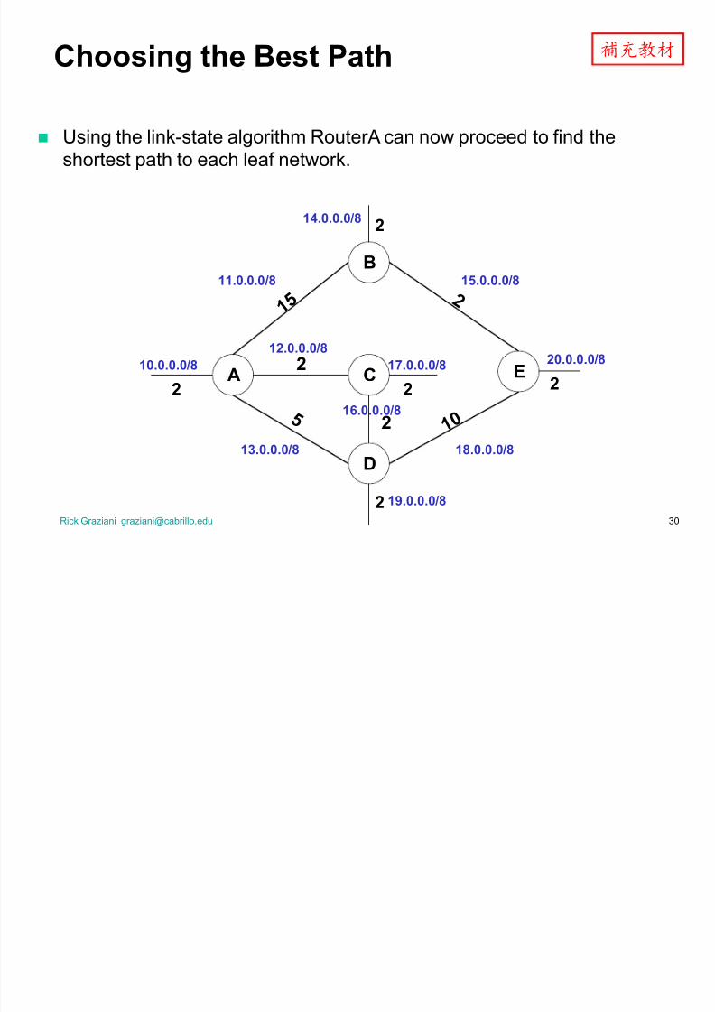
Using the link-state algorithm RouterA can now proceed to find the
shortest path to each leaf network.
A C
D
2
5
B
E
1 52
1 02
2
2
2
22
11.0.0.0 /8
14.0.0.0 /8
12.0.0.0 /8
13.0.0.0 /8
17.0.0.0 /8
16.0.0.0 /8
15.0.0.0 /8
18.0.0.0 /8
20.0.0.0 /8
19.0.0.0 /8
10.0.0.0 /8
Choosing the Best Path

8/8/2019 Single Area OSPF Slides
http://slidepdf.com/reader/full/single-area-ospf-slides 31/84
Rick Graziani [email protected] 31
Now RouterA knows the best path to each network, creating anSPT (Shortest Path Tree).
A C
D
2
5
B
E
1 52
1 02
2
2
22
11.0.0.0 /8
14.0.0.0 /8
12.0.0.0 /8
13.0.0.0 /8
17.0.0.0 /8
16.0.0.0 /8
15.0.0.0 /8
18.0.0.0 /8
20.0.0.0 /8
19.0.0.0 /8
10.0.0.0 /8
Choosing the Best Path

8/8/2019 Single Area OSPF Slides
http://slidepdf.com/reader/full/single-area-ospf-slides 32/84
Rick Graziani [email protected]
SPT Results Get Put into the Routing
Table
R
outerA¶sR
outing Table10.0.0.0/8 connected e0
11.0.0.0/8 connected s0
12.0.0.0/8 connected s1
13.0.0.0/8 connected s2
14.0.0.0/8 17 s0
15.0.0.0/8 17 s1
16.0.0.0/8 4 s1
17.0.0.0/8 4 s1
18.0.0.0/8 14 s1
19.0.0.0/8 6 s1
20.0.0.0/8 16 s1
A C
D
2
5
B
E
1 52
1 02
2
2
22
11.0.0.0 /8
14.0.0.0 /8
12.0.0.0 /8
13.0.0.0 /8
17.0.0.0 /8
16.0.0.0 /8
15.0.0.0 /8
18.0.0.0 /8
20.0.0.0 /8
19.0.0.0 /8
10.0.0.0 /8
s0
s1
s2
e0
8/8/2019 Single Area OSPF Slides
http://slidepdf.com/reader/full/single-area-ospf-slides 33/84
Rick Graziani [email protected] 33
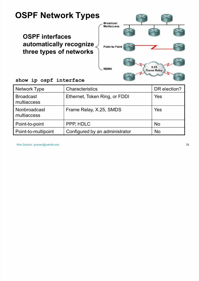
OSPF Network Types
show ip ospf interface
Network Type Characteristics DR election?
Broadcast
multiaccess
Ethernet, Token Ring, or FDDI Yes
Nonbroadcast
multiaccess
Frame Relay, X.25, SMDS Yes
Point-to-point PPP, HDLC No
Point-to-multipoint Configured by an administrator No
OSPF inter f acesautomatically recognize
three types of networks

8/8/2019 Single Area OSPF Slides
http://slidepdf.com/reader/full/single-area-ospf-slides 34/84
Rick Graziani [email protected]
Electing the DR and BDR
Without a DR, the formation of an adjacency between every attached
r outer would create many unnecessary LSA (Link State
Adver tisements), n(n-1) /2 adjacencies.
Flooding on the network itself would be chaotic.
DR DR - Designated Router
BDR BDR ± Backup Designated Router
DR¶s serve as collection points for LinkState Advertisements (LSAs) on multi-access networks
A BDR back ups the DR.
If the IP network is mul ti-access, theOSPF routers will elect one DR and one
BDR
On multi-access, broadcast links (Ethernet), a DR and BDR (if there ismore than one router) need to be elected.
8/8/2019 Single Area OSPF Slides
http://slidepdf.com/reader/full/single-area-ospf-slides 35/84
Rick Graziani [email protected] 35
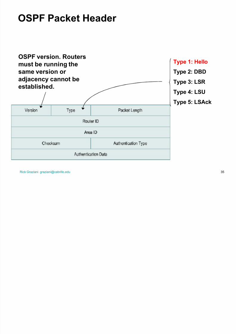
OSPF Packet Header
Type 1: Hello
Type 2: DBD
Type 3: LSR
Type 4: LSU
Type 5: LSAck
OSPF version. Routers
must be r unning the
same version or
adjacency cannot be
established.

8/8/2019 Single Area OSPF Slides
http://slidepdf.com/reader/full/single-area-ospf-slides 36/84
Rick Graziani [email protected]
OSPF Hello Pr otocol
Hello subpr otocol is intended to perform the following tasks withinOSPF:
Dynamic neighbor discovery
Detect unreachable neighbors
Ensure two-way communications between neighbors
Ensure correctness of basic interface parameters between neighbors
Provide necessary information for the election of the Designated and
Backup Designated routers on a LAN segment (coming)

8/8/2019 Single Area OSPF Slides
http://slidepdf.com/reader/full/single-area-ospf-slides 37/84
Rick Graziani [email protected]
OSPF Hello Pr otocol
OSPF routers send Hellos on OSPF enabled interfaces:
±Default every 10 seconds on multi-access and point-to-pointsegments
±Default every 30 seconds on NBMA segments (Frame Relay, X.25, ATM)
±Most cases OSPF Hello packets are sent as multicast to 224.0.0.5
(All OSPF Routers) HelloInterval - Cisco default = 10 seconds or 30 seconds and can be
changed with the command ip ospf hello-interval.
Router DeadInterval - The period in seconds that the router will wait tohear a Hello from a neighbor before declaring the neighbor down.
±Cisco uses a default of fou r-ti mes the HelloInterval (4 x 10 sec.= 40 seconds, 120 secconds for NBMA) and can be changed withthe command ip ospf dead-interval.
Note: For routers to become adjacent, the Hello, DeadInterval andnetwork types must be identical between routers or Hello packets getdropped!

8/8/2019 Single Area OSPF Slides
http://slidepdf.com/reader/full/single-area-ospf-slides 38/84

8/8/2019 Single Area OSPF Slides
http://slidepdf.com/reader/full/single-area-ospf-slides 39/84
Rick Graziani [email protected]
Steps to OSPF Operation with States
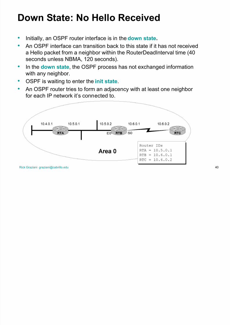
1. Establishing r outer adjacencies (Routers are adjacent) ±Down State ± No Hello received
±Init State ± Hello received, but not with this router¶s Router ID
³Hi, my name is Carlos.´ ³Hi, my name is Maria.´
±Two-way State ± Hello received, and with this router¶s Router ID
³Hi, Maria, my name is Carlos.´ ³Hi, Carlos, my name is Maria.´2. Electing DR and BDR ± Multi-access (br oadcast) segments only
±ExStart State with DR and BDR
±Two-way State with all other routers
3. Discovering Routes
±ExStart State
±Exchange State
±Loading State
±Full State (Routers are ³fully adjacent´)
4. Calculating the Routing Table
5. Maintaining the LSDB and Routing Table
8/8/2019 Single Area OSPF Slides
http://slidepdf.com/reader/full/single-area-ospf-slides 40/84

8/8/2019 Single Area OSPF Slides
http://slidepdf.com/reader/full/single-area-ospf-slides 41/84
Rick Graziani [email protected] 41
The process of establishing adjacencies is asymmetric, meaning the states
between two adjacent routers may be different as they both transition to fullstate.
Trying to start a relationship and wanting to enter the init state or really thetwo-way-state
OSPF routers send multicasts OSPF Hello packets (224.0.0.5, All OSPFRouters), advertising its own Router ID at regular intervals (10 sec.)
Down State

8/8/2019 Single Area OSPF Slides
http://slidepdf.com/reader/full/single-area-ospf-slides 42/84
Rick Graziani [email protected] 42
Hello 10.6.0.1
Hello 10.5.0.1
Hello 10.6.0.1 10.5.0.1
Hello 10.5.0.1 10.6.0.1
DownInit DownInit2-way 2-way
Down State - Init State ± Two Way State
When a router in Down state (sends or) receives its first Hello packet, it
enters the init state, indicating that the Hello packet was received but
did not contain the Router ID of the receiving router in the list of
neighbors, so two-way communications is not yet ensured.
As soon as the router sends a Hello packet to the neighbor with its
RouterID and the neighbor sends a Hello packet packet back with that
Router ID, the router¶s interface will transition to the two-way state.
Now, the router is ready to take the relationship to the next level.
Establishing Adjacencies

8/8/2019 Single Area OSPF Slides
http://slidepdf.com/reader/full/single-area-ospf-slides 43/84
Rick Graziani [email protected] 43
Down Init Two-way
10.5.0.1 10.6.0.1
down
Hello
10.5.0.1
init
Hello 10.6.0.1 10.5.0.1
two-way
init

8/8/2019 Single Area OSPF Slides
http://slidepdf.com/reader/full/single-area-ospf-slides 44/84
Rick Graziani [email protected] 44
Two-way state
RTB now decides who to establish a ³full adjacency´ with depending upon the
type of network that the particular interfaces resides on.
Note: The term adjacency is used to both describe routers reaching 2-way state
and when they reach full-state. Not to go overboard on this, but technically
OSPF routers are adjacent when the FSM reaches full-state and IS-IS is
considered adjacent when the FSM reaches 2-way state.
Two-way state to ExStar t state
If the interface is on a point-to-point link, the routers becomes adjacent with its
sole link partner (aka ³soul mates´), and take the relationship to the next level
by entering the ExStar t state. (coming soon)
Remaining in the two-way state
If the interface is on a multi-access link (Ethernet, Frame Relay, «) RTB must
enter an election process to see who it will establish a full adjacency with, and
remains in the two-way state. (Next!)
Two-way State

8/8/2019 Single Area OSPF Slides
http://slidepdf.com/reader/full/single-area-ospf-slides 45/84
Rick Graziani [email protected]
Steps to OSPF Operation with States
1. Establishing r
outer adjacencies (
Routers are adjacen
t)
±Down State ± No Hello received
±Init State ± Hello received, but not with this router¶s Router ID
³Hi, my name is Carlos.´ ³Hi, my name is Maria.´
±Two-way State ± Hello received, and with this router¶s Router ID
³Hi, Maria, my name is Carlos.´ ³Hi, Carlos, my name is Maria.´2. Electing DR and BDR ± Multi-access (br oadcast) segments only
±ExStart State with DR and BDR
±Two-way State with all other routers
3. Discovering Routes
±ExStart State
±Exchange State
±Loading State
±Full State (Routers are ³fully adjacent´)
4. Calculating the Routing Table
5. Maintaining the LSDB and Routing Table
8/8/2019 Single Area OSPF Slides
http://slidepdf.com/reader/full/single-area-ospf-slides 46/84
Rick Graziani [email protected]
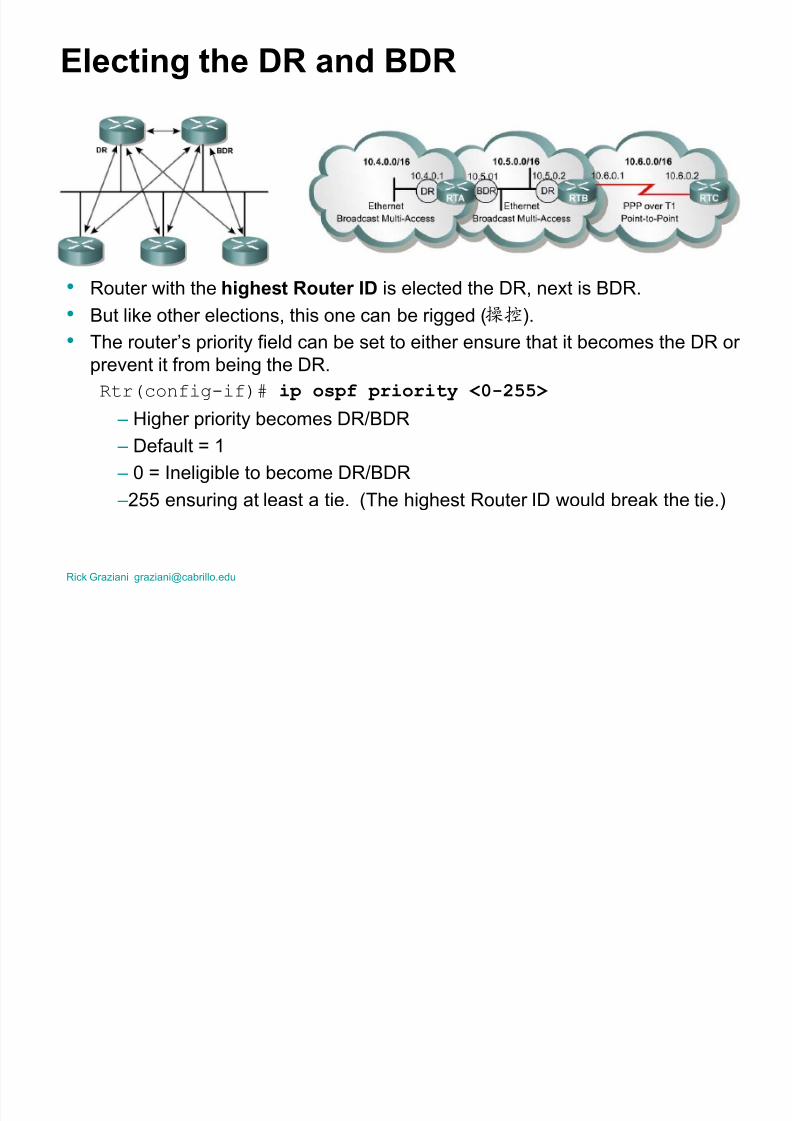
Electing the DR and BDR
Router with the highest Router ID is elected the DR, next is BDR.
But like other elections, this one can be rigged ().
The router¶s priority field can be set to either ensure that it becomes the DR or
prevent it from being the DR.
Rtr(config-if)# ip ospf priority <0-255>
± Higher priority becomes DR/BDR ± Default = 1
± 0 = Ineligible to become DR/BDR
±255 ensuring at least a tie. (The highest Router ID would break the tie.)

8/8/2019 Single Area OSPF Slides
http://slidepdf.com/reader/full/single-area-ospf-slides 47/84
Rick Graziani [email protected]
Electing the DR and BDR
All other routers, ³DROther ́, establish adjacencies with only the DR and BDR. DRother routers multicast LSAs to only the DR and BDR
± (224.0.0.6 - all DR routers)
DR sends LSA to all adjacent neighbors (DROthers)
±(224.0.0.5 - all OSPF routers)
Backup Designated Router - BDR
Listens, but doesn¶t act.
If LSA is sent, BDR sets a timer.
If timer expires before it sees the reply from the DR, it becomes the DR andtakes over the update process.
The process for a new BDR begins.
8/8/2019 Single Area OSPF Slides
http://slidepdf.com/reader/full/single-area-ospf-slides 48/84
Rick Graziani [email protected]
Electing the DR and BDR
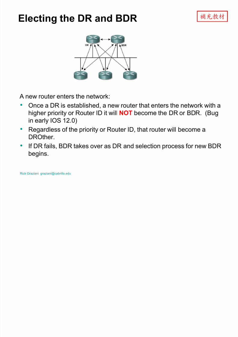
A new router enters the network:
Once a DR is established, a new router that enters the network with a
higher priority or Router ID it will NOT become the DR or BDR. (Bug
in early IOS 12.0)
Regardless of the priority or Router ID, that router will become a
DROther.
If DR fails, BDR takes over as DR and selection process for new BDR
begins.

8/8/2019 Single Area OSPF Slides
http://slidepdf.com/reader/full/single-area-ospf-slides 49/84
Rick Graziani [email protected] 49
Clarif ications
Hello
packets are still exchanged between all routers on amulti-access segment (DR, BDR, DROthers,«.) to
maintain neighbor adjacencies.
OSPF LSA packets (coming) are packets which are sent
from the BDR/DROthers to the DR, and then from the DR
to the BDR/DROthers. (The reason for a DR/BDR.)
Normal routing of IP packets still takes the lowest cost
route, which might be between two DROthers.

8/8/2019 Single Area OSPF Slides
http://slidepdf.com/reader/full/single-area-ospf-slides 50/84
Rick Graziani [email protected]
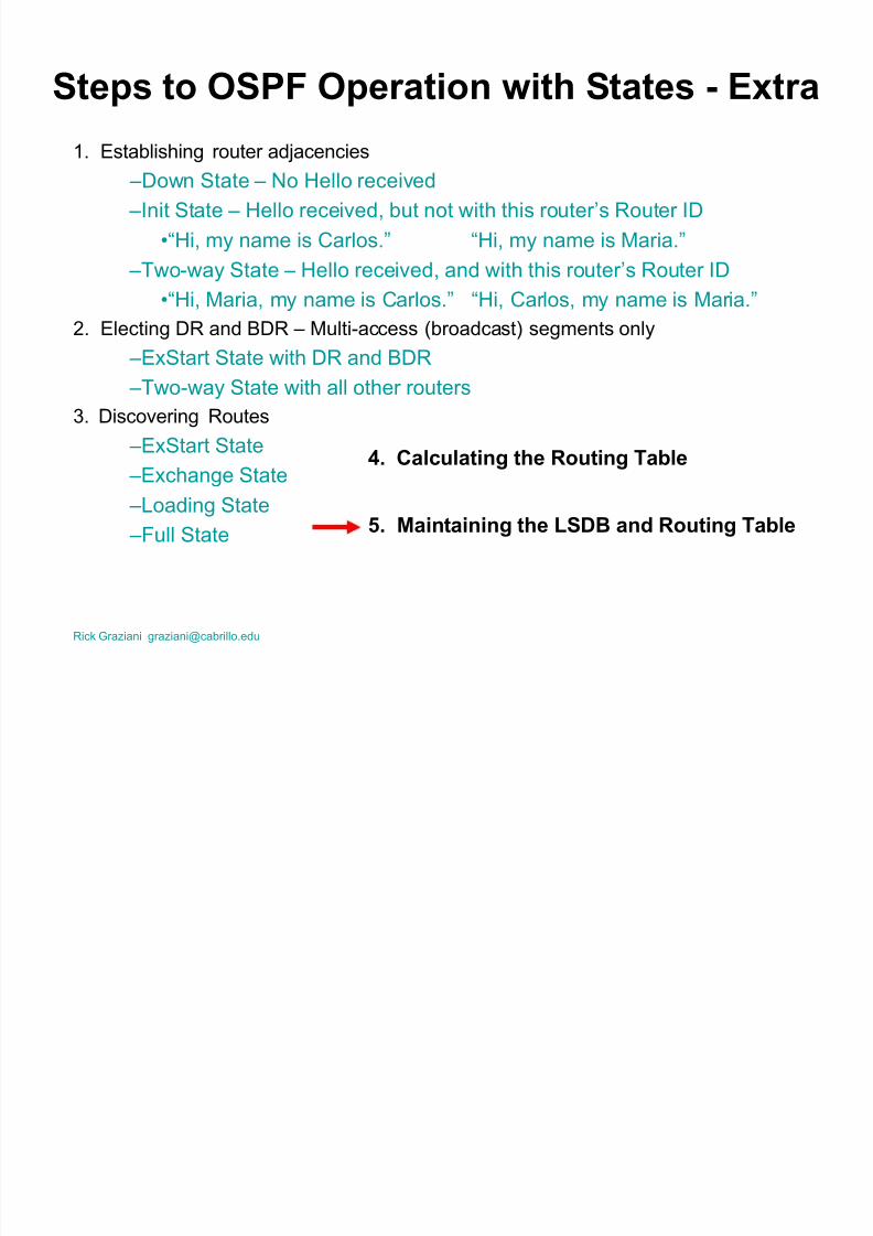
Steps to OSPF Operation with States - Extra
1. Establishing router adjacencies ±Down State ± No Hello received
±Init State ± Hello received, but not with this router¶s Router ID
³Hi, my name is Carlos.´ ³Hi, my name is Maria.´
±Two-way State ± Hello received, and with this router¶s Router ID
³Hi, Maria, my name is Carlos.´ ³Hi, Carlos, my name is Maria.´
2. Electing DR and BDR ± Multi-access (broadcast) segments only
±ExStart State with DR and BDR
±Two-way State with all other routers
3. Discovering Routes
±ExStart State
±Exchange State
±Loading State
±Full State
4. Calcu
lating
the
Routing Table
5. Maintaining the LSDB and Routing Table
8/8/2019 Single Area OSPF Slides
http://slidepdf.com/reader/full/single-area-ospf-slides 51/84

8/8/2019 Single Area OSPF Slides
http://slidepdf.com/reader/full/single-area-ospf-slides 52/84
Conf iguring Single Area OSPFI t¶s easy !

8/8/2019 Single Area OSPF Slides
http://slidepdf.com/reader/full/single-area-ospf-slides 53/84
Rick Graziani [email protected]
Enabling OSPF
R tr(config)# router ospf process-id
pr ocess-id: 1 - 65,535
Cisco feature, which allows you to run multiple, different OSPF routing
processes on the same router. (But don¶t!) Pr ocess-id is locally signif icant, and does not have to be the same
number on other routers (they don¶t care).
This is different than the process-id used for IGRP and EIGRP which
must be the same on all routers sharing routing information.
Extra: FYI - Cisco IOS limits the number of dynamic routing processesto 30. This is because it limits the number of protocol descriptors to 32,
using one for connected route sources, one for static route sources,
and 30 for dynamic route sources.

8/8/2019 Single Area OSPF Slides
http://slidepdf.com/reader/full/single-area-ospf-slides 54/84
Rick Graziani [email protected]
Conf iguring the Network Command
Rtr(config)# router ospf p rocess-id
Rtr(config-router)#network address wildcard-mask areaarea-id
Tells OSPF which interfaces to enable OSPF on (send and receive
updates), matching the address and wildcard mask. Also, tells OSPF to include this network in its routing updates
Wildcard is necessary because OSPF supports CIDR and VLSM
Most of the time you can just use an inverse-mask (like access-lists) asthe network wildcard mask.
Rtr(config-if)#ip address 10.5.1.1 255.255.255.0
Rtr(config)# router ospf 10
Rtr(config-router)#network 10.5.1.0 0.0.0.255 area 0

8/8/2019 Single Area OSPF Slides
http://slidepdf.com/reader/full/single-area-ospf-slides 55/84
Rick Graziani [email protected] 55
Network Command and the Wildcard Mask
S0 S0f a0 f a0
Router ID: lo0 200.0.0.1 /32
lo1 lo1
Merida Vargas
192.168.1.0 /24192.168.30.0 /24
192.168.20.4.0 /30192.168.2.0 /24
192.168.20.0 /30
.1.2
.5
Non-OSPF link
.1 .1
.1
Router ID: lo0 201.0.0.1 /32
M erida
M erida(config)#router ospf 1
M erida(config-router)#network 192.168.1.0 0.0.0.255 area 0
M erida(config-router)#network 192.168.2.0 0.0.0.255 area 0
M erida(config-router)#network 192.168.20.0 0.0.0.3 area 0
Vargas
Vargas(config)#router ospf 10
Vargas(config-router)#network 192.168.20.0 0.0.0.3 area 0
Vargas(config-router)#network 192.168.30.0 0.0.0.255 area 0
Only
192.168.20.0 /30
255.255.255.252
NOT
192.168.20.4 /30

8/8/2019 Single Area OSPF Slides
http://slidepdf.com/reader/full/single-area-ospf-slides 56/84
Rick Graziani [email protected] 56
Network Command and the Wildcard Mask
S0 S0f a0 f a0
Router ID: lo0 200.0.0.1 /32
lo1 lo1
Merida Vargas
192.168.1.0 /24192.168.30.0 /24
192.168.20.4.0 /30192.168.2.0 /24
192.168.20.0 /30
.1.2
.5
Non-OSPF link
.1 .1
.1
Router ID: lo0 201.0.0.1 /32
Vargas(config-router)#network 192.168.20.0 0.0.0.3 area 0
Only
192.168.20.0 /30
NOT
192.168.20.4 /30
First three octets of the address must match 192.168.3.0 0.0.0.3
Last octet of the network address is 0 = 00000000
Last octet of the wildcard mask address is 3 = 00000011
M ust match the first 6 bits of the address 000000
Don¶t care about the last two bits of the address 11 µAddresses¶ that would match 00000000, 00000001, 00000010, 00000011
192.168.20.0, 192.168.20.1, 192.168.20.2, 192.168.20.3
µAddress¶ that does NOT match: 00000101 or 192.168.20.5

8/8/2019 Single Area OSPF Slides
http://slidepdf.com/reader/full/single-area-ospf-slides 57/84
Rick Graziani [email protected]
Conf iguring the Network Command - Extra
Other times you may wish to get more specif ic or less specif ic.
Rtr(config-if)#ip address 10.5.1.1 255.255.255.0
Rtr(config)# router ospf 10
Rtr(config-router)#network 0.0.0.0 255.255.255.255 area 0
Matches all interfaces on this router, not recommended
Rtr(config)# router ospf 10
Rtr(config-router)#network 10.5.1.2 0.0.0.0 area 0
Matches only the interface 10.5.1.2 and not any other 10.5.1.n interfaces.
Fr om Routing TCP /IP Vol. I, Jeff Doyle

8/8/2019 Single Area OSPF Slides
http://slidepdf.com/reader/full/single-area-ospf-slides 58/84
Rick Graziani [email protected] 58
Rubens
router ospf 10
network 0.0.0.0 255.255.255.255 area 1
This will match all interfaces on the router.
The address 0.0.0.0 is just a placeholder, the inverse mask of 255.255.255.255
does the actual matching with ³don¶t care´ bits placed across the entire four
octets of the address. This method provides the least precision control and is generally discouraged
against, as you may bring up another interface on the router and you did not
mean to run OSPF on that interface.
Chardin Goya Matisse
192.168.30.0 /29
Rubens
192.168.20.0 /30 192.168.10.0 /27
.1 .9 .10 .1 .2 .1 .2 .65
192.168.10.0 /26
Area 1 Area 0 Area 192.168.10.0
.33
192.168.10.0 /28
Extra Info
Fr om Routing TCP /IP Vol. I, Jeff Doyle

8/8/2019 Single Area OSPF Slides
http://slidepdf.com/reader/full/single-area-ospf-slides 59/84
Rick Graziani [email protected] 59
Chardin
router ospf 20
network 192.168.30.0 0.0.0.255 area 1
network 192.168.20.0 0.0.0.255 area 0
Chardin is a ABR (Area Border Router) which we will discuss next chapter, and
belongs to two different areas.
We need to be more specific here as each interface belongs to a different area.
Here we are saying that any interface that has 192.168.30.n in the first threeoctets belongs to area 1 and any interface that has 192.168.20.n in the first
three octets belongs to area 0.
Notice that the inverse mask does not have to inversely match the subnet mask
of the interface (255.255.255.248 and 255.255.255.252).
Chardin Goya Matisse
192.168.30.0 /29
Rubens
192.168.20.0 /30 192.168.10.0 /27
.1 .9 .10 .1 .2 .1 .2 .65
192.168.10.0 /26
Area 1 Area 0 Area 192.168.10.0
.33
192.168.10.0 /28
Extra Info
Fr om Routing TCP /IP Vol. I, Jeff Doyle

8/8/2019 Single Area OSPF Slides
http://slidepdf.com/reader/full/single-area-ospf-slides 60/84
Rick Graziani [email protected] 60
Goya
router ospf 30
network 192.168.20.0 0.0.0.3 area 0.0.0.0
network 192.168.10.0 0.0.0.31 area 192.168.10.0
Goya is also an ABR.
The network statements will only match the specific subnets configured on the
two interfaces.
/30 = 255.255.255.252 = 11111100 00 = host bits
3 = 00000011 - M atch last two bits of subnet mask
/27 = 255.255.255.224 = 11100000 00000 = host bits
31 = 00011111 - M atch last five bits of subnet mask
Chardin Goya Matisse
192.168.30.0 /29
Rubens
192.168.20.0 /30 192.168.10.0 /27
.1 .9 .10 .1 .2 .1 .2 .65
192.168.10.0 /26
Area 1 Area 0 Area 192.168.10.0
.33
192.168.10.0 /28
Extra Info
Fr om Routing TCP /IP Vol. I, Jeff Doyle

8/8/2019 Single Area OSPF Slides
http://slidepdf.com/reader/full/single-area-ospf-slides 61/84
Rick Graziani [email protected] 61
Goya
router ospf 30
network 192.168.20.0 0.0.0.3 area 0.0.0.0
network 192.168.10.0 0.0.0.31 area 192.168.10.0
Goya is also an ABR.
Also notice that you can use an dotted decimal notation to represent an area.
In my experience it is not very common, but when it is used, most people use
the network address.
Area 0 can be represented as 0 or 0.0.0.0.
± When the dotted decimal is used OSPF packets are converted to ³0´
so the two can be compatible.
Chardin Goya Matisse
192.168.30.0 /29
Rubens
192.168.20.0 /30 192.168.10.0 /27
.1 .9 .10 .1 .2 .1 .2 .65
192.168.10.0 /26
Area 1 Area 0 Area 192.168.10.0
.33
192.168.10.0 /28
Extra Info

8/8/2019 Single Area OSPF Slides
http://slidepdf.com/reader/full/single-area-ospf-slides 62/84
8/8/2019 Single Area OSPF Slides
http://slidepdf.com/reader/full/single-area-ospf-slides 63/84
Rick Graziani [email protected]
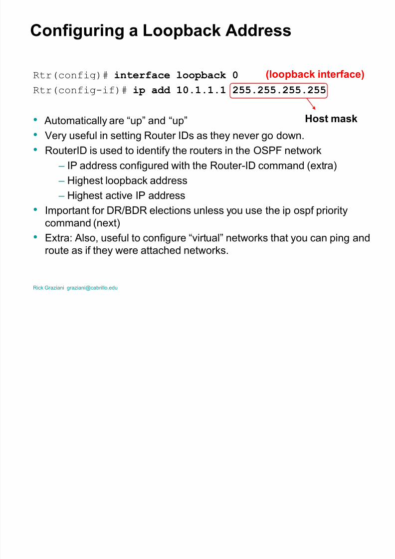
Conf iguring a Loopback Address
Rtr(config)# interface loopback 0Rtr(config-if)# ip add 10.1.1.1 255.255.255.255
Automatically are ³up´ and ³up´
Very useful in setting Router IDs as they never go down.
RouterID is used to identify the routers in the OSPF network
± IP address configured with the Router-ID command (extra)
± Highest loopback address
± Highest active IP address
Important for DR/BDR elections unless you use the ip ospf prioritycommand (next)
Extra: Also, useful to configure ³virtual´ networks that you can ping and
route as if they were attached networks.
(loopback inter f ace)
Host mask

8/8/2019 Single Area OSPF Slides
http://slidepdf.com/reader/full/single-area-ospf-slides 64/84
Rick Graziani [email protected]
DR/BDR Elections
Router with the highest Router ID is elected the DR, next is BDR.
But like other elections, this one can be rigged.
Rtr(config)# interface fastethernet 0
Rtr(config-if)# ip ospf priority <0-255>
Higher priority becomes DR/BDR
Default = 1
Ineligible to become DR/BDR = 0

8/8/2019 Single Area OSPF Slides
http://slidepdf.com/reader/full/single-area-ospf-slides 65/84
Rick Graziani [email protected]
show ip ospf inter f ace
R outer# show ip ospf interface
Ethernet0 is up, line protocol is up
Internet Address 206.202.2.1/24, Area 1
Process ID 1, R outer ID 1.2.202.206, Network Type BR OADCAST, Cost: 10
Transmit Delay is 1 sec, State BDR , Priority 1
Designated R outer (ID) 2.2.202.206, Interface address 206.202.2.2
Backup Designated router (ID) 1.2.202.206, Interface address 206.202.2.1
Timer intervals configured, Hello 10, Dead 40, Wait 40,R
etransmit 5Hello due in 00:00:00
Neighbor Count is 1, Adjacent neighbor count is 1
Adjacent with neighbor 2.2.202.206 (Designated R outer)
Suppress hello for 0 neighbor(s)
Serial0 is up, line protocol is up
Internet Address 206.202.1.2/24, Area 1
Process ID 1, R outer ID 1.2.202.206, Network Type POINT_TO_POINT, Cost:64
Transmit Delay is 1 sec, State POINT_TO_POINT,
Timer intervals configured, Hello 10, Dead 40, Wait 40, R etransmit 5
Hello due in 00:00:04
Neighbor Count is 1, Adjacent neighbor count is 1
Adjacent with neighbor 2.0.202.206
Suppress hello for 0 neighbor(s)
8/8/2019 Single Area OSPF Slides
http://slidepdf.com/reader/full/single-area-ospf-slides 66/84
C fi i Si l A th ti ti

8/8/2019 Single Area OSPF Slides
http://slidepdf.com/reader/full/single-area-ospf-slides 67/84
Rick Graziani [email protected]
Conf iguring Simple Authentication
A router, by default, trusts that routing information received, has come from arouter that should be sending it.
Rtr(config-if)# ip ospf authentication-key p asswd
Configured on an interface
password = Clear text unless message-digest is used (next) ±Easily captured using a packet sniffer
±Passwords do not have to be the same throughout an area, but they must
be same between neighbors.
After a password is configured, you enable authentication for the area on allparticipating area routers with:
Rtr(config-router)# area area authentication
Configured for an OSPF area, in ospf router mode.
C fi i Si l A th ti ti

8/8/2019 Single Area OSPF Slides
http://slidepdf.com/reader/full/single-area-ospf-slides 68/84
Rick Graziani [email protected]
Conf iguring Simple Authentication
R outerA
interface Serial1
ip address 192.16.64.1 255.255.255.0
ip ospf authentication-key secret
!
router ospf 10
network 192.16.64.0 0.0.0.255 area 0network 70.0.0.0 0.255.255.255 area 0
area 0 authentication
R outerB
interface Serial2
ip address 192.16.64.2 255.255.255.0
ip ospf authentication-key secret
!
router ospf 10
network 172.16.0.0 0.0.255.255 area 0network 192.16.64.0 0.0.0.255 area 0
area 0 authentication
s1 s2
192.16.64.1/24 192.16.64.2/24
70.0.0.0/8 172.16.0.0/16
RouterA RouterB
C fi i MD5 E t d A th ti ti

8/8/2019 Single Area OSPF Slides
http://slidepdf.com/reader/full/single-area-ospf-slides 69/84
Rick Graziani [email protected]
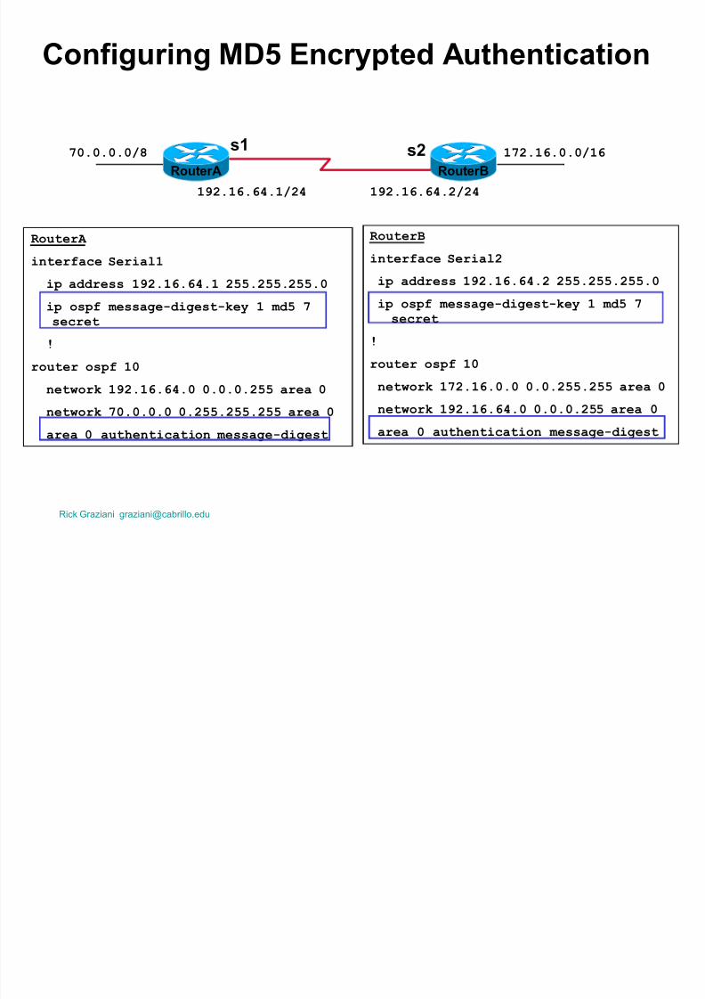
Conf iguring MD5 Encrypted Authentication
Rtr(config-if)# ip ospf message-digest-key key-id md5encry p tion-ty p e key
k ey -id = 1 to 255, must match on each router to authenticate.
encr y ption t y pe = type of encryption, where 0 means none and 7means proprietary.
k ey = an alphanumeric password up to sixteen characters
±Passwords do not have to be the same throughout an area, butthey must be same between neighbors.
After a password is configured, you enable authentication for the area onall participating area routers with:
Rtr(config-router)# area area authentication message-digest
message-digest option must be used if using message-digest-key
If optional message-digest is used, a message digest, or hash, of thepassword is sent.
C fi i MD5 E t d A th ti ti
8/8/2019 Single Area OSPF Slides
http://slidepdf.com/reader/full/single-area-ospf-slides 70/84
Rick Graziani [email protected]
Conf iguring MD5 Encrypted Authentication
R outerA
interface Serial1
ip address 192.16.64.1 255.255.255.0
ip ospf message-digest-key 1 md5 7secret
!
router ospf 10
network 192.16.64.0 0.0.0.255 area 0
network 70.0.0.0 0.255.255.255 area 0
area 0 authentication message-digest
R outerB
interface Serial2
ip address 192.16.64.2 255.255.255.0
ip ospf message-digest-key 1 md5 7secret
!
router ospf 10
network 172.16.0.0 0.0.255.255 area 0
network 192.16.64.0 0.0.0.255 area 0
area 0 authentication message-digest
s1 s2
192.16.64.1/24 192.16.64.2/24
70.0.0.0/8 172.16.0.0/16
RouterA RouterB
MD5 E ti

8/8/2019 Single Area OSPF Slides
http://slidepdf.com/reader/full/single-area-ospf-slides 71/84
Rick Graziani [email protected]
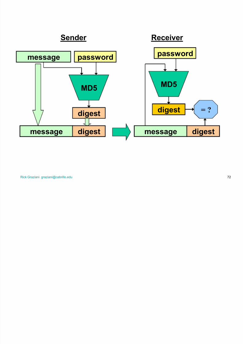
MD5 Encryption
MD5 authentication, creates a message digest.
This is scrambled data that is based on the password and the
packet contents .
The receiving router uses the shared password and the packet
to re-calculate the digest. If the digests match, the router believes that the source of the
packet and its contents have not been tampered with.
In the case of message-digest authentication, the authentication
data field contains the k ey -id and the length of the message
digest that is appended to the packet.
The Message Digest is like a watermark that can¶t be faked.
8/8/2019 Single Area OSPF Slides
http://slidepdf.com/reader/full/single-area-ospf-slides 72/84
Rick Graziani [email protected] 72
message password
MD5
digest
message digest message digest
password
MD
5
digest = ?
Sender Receiver
C fi i OSPF Ti

8/8/2019 Single Area OSPF Slides
http://slidepdf.com/reader/full/single-area-ospf-slides 73/84
Rick Graziani [email protected]
Conf iguring OSPF Timers
Rtr(config-if)# ip ospf hello-interval seconds
Rtr(config-if)# ip ospf dead-interval seconds
Configured on an interface
For OSPF routers to be able to exchange information, the must have the same
hello intervals and dead intervals. By default, the dead interval is 4 times the hello interval, so the a router has
four chances to send a hello packet being declared dead. (not required)
In multi-vendor networks, Hello timers may need to be adjusted.
Do not modify defaults unless you have a compelling need to do so.
Def au
lts
On broadcast networks hello interval = 10 seconds, dead interval 40 seconds.
On non-broadcast networks hello interval = 30 seconds, dead interval 120
seconds.
Note: On some IOS¶s, the dead-interval automatically changes when the hello-
interval is modified.

8/8/2019 Single Area OSPF Slides
http://slidepdf.com/reader/full/single-area-ospf-slides 74/84
Rick Graziani [email protected]
Conf iguring and Pr opagating a Def ault Route
Router(config)# ip route 0.0.0.0 0.0.0.0 serial0
Router(config)# router ospf 1
Router(config-router)# default-information originate
If the ASBR has a default route configured (ip route 0.0.0.0 0.0.0.0), the default-
information originate command is necessary to advertise 0.0.0.0/0 to the other
routers in the area.
If the default-information originate command is not used, the default ³quad-zero´
route will not be propagated.
I mportant : The default route and the default-information originate command are
usually only be configured on your ³Entrance´ or ³Gateway´ router, the router that
connects your network to the outside world.
±This router is known as the ASBR (Autonomous System Boundary Router)
Default Route Example
8/8/2019 Single Area OSPF Slides
http://slidepdf.com/reader/full/single-area-ospf-slides 75/84
Rick Graziani [email protected]
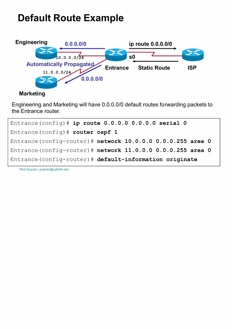
Def ault Route Example
E
ntrance(config)# ip route 0.0.0.0 0.0.0.0 serial 0Entrance(config)# router ospf 1
Entrance(config-router)# network 10.0.0.0 0.0.0.255 area 0
Entrance(config-router)# network 11.0.0.0 0.0.0.255 area 0
Entrance(config-router)# default-information originate
ISPEntrance
Engineering
Marketing
ip r oute 0.0.0.0 /0
Static Route
0.0.0.0 /0
0.0.0.0 /0
Automatically Pr opagated
s010.0.0.0/24
11.0.0.0/24
Engineering and Marketing will have 0.0.0.0/0 default routes forwarding packets to
the Entrance router.

8/8/2019 Single Area OSPF Slides
http://slidepdf.com/reader/full/single-area-ospf-slides 76/84
Rick Graziani [email protected]
show ip r oute
R outer# show ip route172.16.0.0/16 is variably subnetted, 4 subnets, 3 masks
O IA 172.16.51.1/32 [110/783] via 172.16.1.2, 00:11:44,FastEthernet0
O 172.16.20.0/24 [110/782] via 172.16.10.6, 00:12:29, Serial0
C 172.16.10.4/30 is directly connected, Serial0
C 172.16.1.0/24 is directly connected, FastEthernet0
O E2 11.0.0.0/8 [110/20] via 172.16.1.1, 00:11:44, FastEthernet0
O E1 12.0.0.0/8 [110/782] via 172.16.1.1, 00:11:44, FastEthernet0
O = OSPF routes within the same area (intra-area routes)
110/number = Administrative Distance/metric (cumulative 108/bandwidth)
E2 = Routes outside of the OSPF routing domain, redistributed into OSPF.
± Default is E2 with a cost of 20 and does not get modified within the OSPF
O IA = OSPF routes from another area (inter-area routes)
E1 = Routes outside of the OSPF routing domain and get additional cumulativecosts added on by each router, just like other OSPF routes.

8/8/2019 Single Area OSPF Slides
http://slidepdf.com/reader/full/single-area-ospf-slides 77/84
Rick Graziani [email protected]
show ip ospf
R outer#show ip ospf
R outing Process "ospf 1" with ID 192.168.3.1
Supports only single TOS(TOS0) routes
It is an area border router
SPF schedule delay 5 secs, Hold time between two SPFs 10 secs
M inimum LSA interval 5 secs. M inimum LSA arrival 1 secs
Number of externalL
SA 3. Checksum Sum 0x97E3 Number of DCbitless external LSA 0
Number of DoNotAge external LSA 0
Number of areas in this router is 2. 2 normal 0 stub 0 nssa
External flood list length 0
Area BACKBONE(0)
Number of interfaces in this area is 1 Area has no authentication
SPF algorithm executed 8 times
<text omitted>
Area 1
<text omitted>

8/8/2019 Single Area OSPF Slides
http://slidepdf.com/reader/full/single-area-ospf-slides 78/84
Rick Graziani [email protected]
show ip ospf inter f aceR outer# show ip ospf interface
Ethernet0 is up, line protocol is up
Internet Address 206.202.2.1/24, Area 1
Process ID 1, R outer ID 1.2.202.206, Network Type BR OADCAST, Cost: 10
Transmit Delay is 1 sec, State BDR , Priority 1
Designated R outer (ID) 2.2.202.206, Interface address 206.202.2.2
Backup Designated router (ID) 1.2.202.206, Interface address 206.202.2.1
Timer intervals configured, Hello 10, Dead 40, Wait 40, R etransmit 5
Hello due in 00:00:00 Neighbor Count is 1, Adjacent neighbor count is 1
Adjacent with neighbor 2.2.202.206 (Designated R outer)
Suppress hello for 0 neighbor(s)
Serial0 is up, line protocol is up
Internet Address 206.202.1.2/24, Area 1
Process ID 1, R outer ID 1.2.202.206, Network Type POINT_TO_POINT, Cost:64
Transmit Delay is 1 sec, State POINT_TO_POINT,
Timer intervals configured, Hello 10, Dead 40, Wait 40, R etransmit 5
Hello due in 00:00:04
Neighbor Count is 1, Adjacent neighbor count is 1
Adjacent with neighbor 2.0.202.206
Suppress hello for 0 neighbor(s)

8/8/2019 Single Area OSPF Slides
http://slidepdf.com/reader/full/single-area-ospf-slides 79/84
Rick Graziani [email protected]
show ip ospf neighbor
R outerB#show ip ospf neighbor
Neighbor ID Pri State Dead Time Address Interface
1.5.202.206 1 FULL/DR OTHER 00:00:33 206.202.0.3 Ethernet0
1.10.202.206 1 FULL/BDR 00:00:32 206.202.0.4 Ethernet0
1.0.202.206 1 2WAY/DR OTHER 00:00:30 206.202.0.1 Ethernet0
1.2.202.206 1 FULL/ - 00:00:32 206.202.1.2 Serial0
In this example, we are the DR
DROTHER may be in FULL or 2 WAY state, both cases are normal.
Usually if there are multiple DROTHERs, they will be in either FULL or 2WAY state but not both.

8/8/2019 Single Area OSPF Slides
http://slidepdf.com/reader/full/single-area-ospf-slides 80/84
Rick Graziani [email protected]
debug ip ospf adj (adjacency)
R outer# debug ip ospf adj
04:19:46: OSPF: R cv hello from 201.0.0.1 area 0 from FastEthernet0 192.168.20.1
04:19:46: OSPF: 2 Way Communication to 201.0.0.1 on FastEthernet0, state 2WAY
04:19:46: OSPF: End of hello processing
<text omitted>
04:20:22: OSPF: end of Wait on interface FastEthernet0
04:20:22: OSPF: DR /BDR election on FastEthernet0
04:20:22: OSPF: Elect BDR 200.0.0.1
04:20:22: OSPF: Elect DR
200.0.0.104:20:22: OSPF: Elect BDR 201.0.0.1
04:20:22: OSPF: Elect DR 200.0.0.1
04:20:22: DR : 201.0.0.1 (Id) BDR : 200.0.0.1 (Id)
04:20:23: OSPF: R cv DBD from 201.0.0.1 on FastEthernet0 seq 0x2657 opt 0x2 flag
0x7 len 32 mtu 1500 state EXSTA R T
04:20:23: OSPF: NBR Negotiation Done. We are the SL AVE
04:20:23: OSPF: Send DBD to 201.0.0.1 on FastEthernet0 seq 0x2657 opt 0x2 flag 0 x2 len 92
04:20:23: OSPF: R cv DBD from 201.0.0.1 on FastEthernet0 seq 0x2658 opt 0x2 flag0x3 len 72 mtu 1500 state EXCHANGE
<text omitted>
04:20:23: OSPF: Synchronized with 201.0.0.1 on FastEthernet0, state FULL
Displays adjacency information including Hello pr ocessing, DR/BDR election, authentication, and the ³Steps to OSPF Operation.´

8/8/2019 Single Area OSPF Slides
http://slidepdf.com/reader/full/single-area-ospf-slides 81/84
Rick Graziani [email protected]
debug ip ospf events
R outer# debug ip ospf events
08:00:56: OSPF: R cv hello from 201.0.0.1 area 0 from FastEthernet0 192.168.20.1
08:00:56: OSPF: M ismatched hello parameters from 192.168.20.1
08:00:56: Dead R 40 C 20, Hello R 10 C 5 M ask R 255.255.255.252 C255.255.255.2
52
Shows much of the same information as debug ip ospf adj in the previousslide including, adjacencies, flooding information, designated router selection, and shortest path first (SPF) calculation.
This information is also displayed with debug ip ospf events.
R = Received
C = Current (?)
show ip ospf database

8/8/2019 Single Area OSPF Slides
http://slidepdf.com/reader/full/single-area-ospf-slides 82/84
Rick Graziani [email protected]
show ip ospf database
(summary of link state database)Internal#show ip ospf data
OSPF R outer with ID (192.168.4.1) (Process ID 1)
R outer Link States (Area 0)
Link ID ADV R outer Age Seq# Checksum Link count
192.168.3.1 192.168.3.1 898 0x80000003 0xCE56 2
192.168.4.1 192.168.4.1 937 0x80000003 0xFD44 3
Summary Net Link States (Area 0)
Link ID ADV R outer Age Seq# Checksum
172.16.1.0 192.168.3.1 848 0x80000005 0xD339
172.16.51.1 192.168.3.1 843 0x80000001 0xB329
Summary ASB Link States (Area 0)
Link ID ADV R outer Age Seq# Checksum
192.168.1.1 192.168.3.1 912 0x80000003 0x93CC
Type-5 AS External Link States
Link ID ADV R outer Age Seq# Checksum Tag
11.0.0.0 192.168.1.1 1302 0x80000001 0x3FEA 0
12.0.0.0 192.168.1.1 1303 0x80000001 0x32F6 0
Link states within this area, this is what the SPF uses.
Link states of any DRs in this area.
Link states summaries of links outside this area. (No SPF)
Link states summaries of links external routes. (No SPF)
OSPF Conf iguration Commands - Review

8/8/2019 Single Area OSPF Slides
http://slidepdf.com/reader/full/single-area-ospf-slides 83/84
Rick Graziani [email protected]
gRequired Commands:
Rtr(config)# router ospf p rocess-id
Rtr(config-router)#network address wildcard-mask area area-id
Optional Commands:
Rtr(config-router)# default-information originate (Send default)
Rtr(config-router)# area area authentication (Plain authen.)
Rtr(config-router)# area area authentication message-digest
(md5 authen.)
Rtr(config)# interface loopback number (Configure lo as R trID)Rtr(config)# interface type slot/port
Rtr(config-if)# ip ospf priority <0-255> (DR /BDR election)
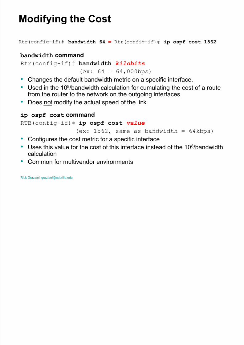
Rtr(config-if)# bandwidth kb p s ( M odify default bandwdth)
RTB(config-if)# ip ospf cost cost ( M odify inter. cost)
Rtr(config-if)# ip ospf hello-interval seconds ( M odify Hello)
Rtr(config-if)# ip ospf dead-interval seconds ( M odify Dead)Rtr(config-if)# ip ospf authentication-key p asswd (Plain/md5authen)
Rtr(config-if)# ip ospf message-digest-key key-id md5 p assword
OSPF Show Commands - Review

8/8/2019 Single Area OSPF Slides
http://slidepdf.com/reader/full/single-area-ospf-slides 84/84
OSPF Show Commands - Review
Router# show ip route
Router# show ip ospf
Router# show ip ospf interface
Router# show ip ospf neighbor
Router# show ip ospf database
Router# debug ip ospf adj
Router# debug ip ospf events (Repor t all OSPF events)
(Repor t OSPF adjacency events)
(topological database)