Embed Size (px)
Citation preview

SINGLE ACTINGTELESCOPIC CYLINDERS(3.5–4.5 SERIES MODELS)
DISASSEMBLY AND REASSEMBLY INSTRUCTIONS MANUAL
Muncie Power Products, Inc.

Muncie Power Products, Inc.3
TABLE OF CONTENTS
SINGLE ACTING TELESCOPIC CYLINDERS(3.5–4.5 SERIES MODELS)REASSEMBLY INSTRUCTIONS MANUAL
Warning & Safety Recommendations ...................................................................................................4
Preliminary Instructions .........................................................................................................................4
Rebuild Recommendations ...................................................................................................................4
Repair Kits ..............................................................................................................................................5
Tools Used .............................................................................................................................................6
Disassembly Instructions .......................................................................................................................7
Reassembly Instructions .....................................................................................................................13
Troubleshooting Information ................................................................................................................19

Muncie Power Products, Inc.4
Warning & Safety Recommendations
When conducting the disassembly and reassembly of a cylinder, it is your responsibility to ensure that you use the proper tools for the job and conduct the job in a safe manner. It is highly recommended that you use safety glasses and wear nonslip steel-toe shoes. Because of the weight of most cylinders, it is highly recommended that you use lifting equipment to move the complete cylinder and its individual stages in order to prevent injury. Please exercise extreme caution during the disassembly and assembly process to ensure your safety and prevent damage to the stages.
Preliminary Instructions
Prior to disassembly, the cylinder must be removed from the truck, drained, and cleaned. Use water and a nonflammable cleaning agent to clean the cylinder.Use a table or bench that is strong enough to hold the weight of a cylinder. The table must be clean and free of debris that may cause damage to the stages or internal components of the cylinder. Any scoring, pitting, or scratches sustained to the stages during a disassembly and reassembly of a cylinder are the sole responsibility of the individual(s) involved in the rebuild process. Damage to the stages can result in damage to internal components, thus causing leaks.
Rebuild Recommendations
It is highly recommended that you conduct a complete rebuild if disassembling a cylinder for any reason. A complete rebuild includes replacement seals, wipers, and guide rings because these are the components that are subject to wear. The seal kit includes only the seals and wipers needed for a cylinder.
It is also recommended that if disassembling due to a leak in one stage, it would be best to replace all internal components instead of just the ones that have failed.It is also highly recommended that you use only genuine Muncie Power Products parts and do not tamper with or modify them. Failure to do so will result in a voided warranty. When ordering rebuild kits, always mention the part number and serial number of the cylinder. These can be found on the tag that is spot welded to the housing.
Muncie Power Products, Inc.5
s
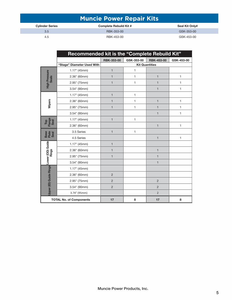
Muncie Power Repair KitsCylinder Series Complete Rebuild Kit # Seal Kit Only#
3.5 RBK-353-00 GSK-353-00
4.5 RBK-453-00 GSK-453-00
Recommended kit is the “Complete Rebuild Kit”RBK-353-00 GSK-353-00 RBK-453-00 GSK-453-00
“Stage” Diameter Used With Kit Quantities
High
Pre
ssur
e Se
als
1.17" (45mm) 1 1
2.36" (60mm) 1 1 1 1
2.95" (75mm) 1 1 1 1
3.54" (90mm) 1 1
Wip
ers
1.17" (45mm) 1 1
2.36" (60mm) 1 1 1 1
2.95" (75mm) 1 1 1 1
3.54" (90mm) 1 1
Top
Flan
ge
Seal 1.17" (45mm) 1 1
2.36" (60mm) 1 1
Base
Pl
ate
Se
al 3.5 Series 1 1
4.5 Series 1 1
Low
er (O
D) G
uide
Ri
ngs
1.17" (45mm) 1
2.36" (60mm) 1 1
2.95" (75mm) 1 1
3.54" (90mm) 1
Uppe
r (ID
) Gui
de R
ings 1.17" (45mm)
2.36" (60mm) 2
2.95" (75mm) 2 2
3.54" (90mm) 2 2
3.74" (95mm) 2
TOTAL No. of Components 17 8 17 8

Muncie Power Products, Inc.6
High Pressure Sealhas shallow groove
Wiper hasbeveled edge
Lower GuideUpper Guide
Tools Used
Below are tools commonly used to disassemble and reassemble a Muncie Power cylinder. It should be noted that due to the weight and construction of the trunnion cylinders (with the outer covering), it is highly recommended that you use a work bench or test stand designed for the purpose of working on telescopic cylinders. Additionally, proper lifting equipment should also be used to lift and move heavy objects. Safety glasses and nonslip steel-toe shoes are also recommended.
List of Tools Used
Hard Plastic Driver
3 lbs. Sledge Hammer
Small, Medium, and Large Straight Blade Screw Drivers
Standard Hammer
90º Pick
8mm Allen Head Screw Driver
10mm Allen Head Screw Driver
Hoist

Muncie Power Products, Inc.7
DISASSEMBLY
1. Secure the trunnion cylinder as shown in the picture below, or in a similar manner as is shown. Note that the main housing of the cylinder is being supported by a mechanical jack while the outer “bell” housing cover (in this document called the outer cover) is being supported by a hydraulic jack. Each need to be individually supported, and the outer cover will need a strap or chain securing it in place.
2. Remove the 60mm nut using a wrench or an impact wrench with a 60mm socket.

Muncie Power Products, Inc.8
DISASSEMBLY
3. With the 60mm nut removed from the cylinder, you can now pull the outer cover off of the assembly. Be careful when removing the outer cover as it may be heavy. Additionally, take care not to damage the stages of the cylinder as several of them could be exposed. Note that the main body of the cylinder may need to be held up by a jack stand.
4. Secure the cylinder so that it is possible to begin removal of the stages.

Muncie Power Products, Inc.9
5. If not already done, be sure to drain the oil and leave the plug out of the port prior to moving on to any further steps.
6. At the base of the cylinder, use a stiff elastic rod and a hammer, or make use of a press, to push the bottom plate into the cylinder 0.5–1" to access the snap ring.
DISASSEMBLY

Muncie Power Products, Inc.10
7. Remove the snap ring.
8. Now, remove the base plate using a plate extraction tool, or with a press, push the stages back into the cylinder and press the bottom plate out of the cylinder.
DISASSEMBLY

Muncie Power Products, Inc.11
10. Using the stiff elastic rod and the hammer, drive the small stage back toward the bottom of the cylinder. Once the stage has made it past the seal, the stage can be pulled out by hand. Use caution as the weight of the various stages may require the use of a lifting device.
11. Remove the wiper, the guide ring(s), and the high pressure seal from the top end of the stage in the cylinder.
DISASSEMBLY
High Pressure SealGuide RingsWiper

Muncie Power Products, Inc.12
12. Remove guide rings from the bottom of the stage that was removed from the cylinder.
13. Repeat steps 9–12 until all stages have been removed from the cylinder. Always work from the smallest diameter out to the largest diameter stage during disassembly.
DISASSEMBLY
9a 9b 10
11a 11b 11c
11d 12

Muncie Power Products, Inc.13
14. After having disassembled the various components of the cylinder, it is very important to clean the stages with water and a nonflammable cleanser. Be sure to check for any defects in the stages. Any scratches, distortions, or dents may cause leaks.
15. With the stages and housing now clean, begin reassembly of the cylinder. Start with the largest stage and work toward the smallest.
16. Make sure that the main housing of the cylinder is held securely to the work bench.
REASSEMBLY
17. Start by applying white lithium grease to the internal surface where the high pressure seal, wear rings, and wiper will be installed.
18. Install the high pressure seal. The flat end of the seal will need to face the top of the cylinder while the groove end of the seal faces the bottom of the cylinder.

Muncie Power Products, Inc.14
REASSEMBLY
19. Install the wiper.
20. Install the guide rings. The raised ledge end of one of the guide rings will seat right behind the high pressure seal.
High Pressure Seal
Guide Ring
Wiper

Muncie Power Products, Inc.15
21. Install the lower guide rings on the next stage. (which will be installed into the cylinder next.) Be sure to examine the stage for any damage or defects prior to installing into the cylinder.
22. Install the next stage into the cylinder. This will require using the stiff, elastic rod and a hammer. Be careful not to damage the stages as you install them into the cylinder. NOTE: You may need to center the stage as you install it, otherwise the stop on the bottom of the stage may catch and prevent the stage from sliding into the cylinder.
23. Install the snap ring(s) at the bottom of the stage(s) after you drive each stage into the cylinder.
REASSEMBLY
Snap Ring(s)

Muncie Power Products, Inc.16
REASSEMBLY
24. Repeat steps 17–23 until all stages have been installed into the cylinder. Make sure that all high pressure seals, guide rings, and wipers have been installed.
18 19
17
20
21
22 23

Muncie Power Products, Inc.17
REASSEMBLY
25. With all stages now installed into the cylinder, drive the stages into the cylinder far enough so that you can add the base plate, along with its its new seal.
26. Reinstall the base plate by driving it in using the stiff, elastic rod and a hammer. Be sure you have replaced the base place seal before installing the plate.
27. Secure the plate by installing the base plate snap ring.
Snap Ring

Muncie Power Products, Inc.18
28. Guide the cylinder into the outer cover
29. Secure the outer cover to the smallest stage by adding the washer and 60mm nut. Use a 60mm impact socket and impact wrench to secure the nut.
30. If you have the capability to test the cylinder, do so now. Fully cycle the cylinder several times checking for leaks. If a test stand is not available, install into a truck and cycle the cylinder several times. Because the cylinder is self-bleeding, it may take 8–10 cycles before all of the air has bled out.
REASSEMBLY

Muncie Power Products, Inc.19
TROUBLESHOOTING INFORMATION
Condition Likely Cause CorrectionCylinder does not extend No oil in reservoir. Fill reservoir with approved fluid.
Close shut-off valve. Open valve.
Air trapped in pump. Purge air from pump
Pump rotation incorrect. Replace or reconfigure pump to correct rotation.
Hoses plumbed incorrectly. Correct the plumbing.
PTO not engaged. See “PTO Troubleshooting.”
Pump worn or damaged. Repair or replace pump.
Load is causing system pressure to exceed relief pressure setting.
Check relief setting and adjust accordingly. Do not exceed cylinder maximum pressure.
Remove excess load.
Cylinder stages bent or bulged due to side load, misalignment, or over pressurization.
Check for misalignment of cylinder hinges or mounting with frame, and the hinges of the dump body and frame.
Replace damaged cylinder and verify alignment of mounting and hinge points.
Cylinder diameter to small for the application. Consult body builder manufacturer to determine the proper cylinder for the application.
Relief valve improperly set. Adjust relief valve to manufacturer’s specification.
Relief valve stuck open. Remove, clean, and reset to specifications.
Cylinder does not retract or at least one stage does not retract.
Dump angle too great resulting in not enough body weight to collapse cylinder. (or cylinder too long.)
Remove cylinder, stroke too long.
Valve and or hoses too small causing excessive pressure differential.
Replace with larger valve and or hoses. Or disengage PTO for lower function.
Cylinder stages bent or bulged due to side load, misalignment, or over pressurization.
Check for misalignment of cylinder hinges or mounting with frame, and the hinges of the dump body and frame.
Replace damaged cylinder and verify alignment of mounting and hinge points.
Cylinder has become bent due to improper dump procedure.
Replace cylinder.
Valve not shifted properly. Repair or replace valve.
Cylinder operates, but with a “jerky” motion.
Air trapped in cylinder. Cycle cylinder 8–10 times. Muncie Power Products cylinders will self bleed.
Cylinder does not retract initially when the valve is engaged, but suddenly drops after a few seconds.
Air trapped in cylinder Cycle cylinder 8–10 times. Muncie Power Products cylinders will self bleed.
Cylinder stages bent or bulged due to side load, misalignment, or over pressurization.
Check for misalignment of cylinder hinges or mounting with frame, and the hinges of the dump body and frame.
Replace damaged cylinder and verify alignment of mounting and hinge points.
This symbol indicates a hazardous situation which, if not avoided, could result in death or serious injury.

Muncie Power Products, Inc.20
TROUBLESHOOTING INFORMATION CONTINUED
This symbol indicates a hazardous situation which, if not avoided, could result in death or serious injury.
Condition Likely Cause CorrectionAn “oil” like substance is dripping from the cylinder.
During construction, white lithium grease is used to lubricate internal components that will not be exposed to oil. As it heats up, it may drain down the side of the cylinder
Wipe away the grease, over time this will subside. If not, oil may be leaking past the seal, at which point the cylinder will need repaired or replaced.
Leakage from port(s). DO NOT use Teflon pipe tape on fittings..
Loose or damaged fitting. Tighten or replace fitting.
Cylinder too slow while extending. Pump sized too small for application. Change pump or PTO for proper application.
PTO speed to slow for application. Change pump or PTO for proper application.
Low engine RPM. Raise engine RPM.
Relief valve improperly set. Adjust relief valve to manufacturer’s specification.
Relief valve stuck open. Remove, clean, and reset to specification.
Cylinder to slow while retracting. Valve and or hoses too small causing excessive pressure differential.
Replace with larger valve and or hoses. Or disengage PTO for lower function.
Cylinder to fast while extending Pump sized too large for application. Change pump or PTO for proper application
PTO speed to fast for application. Change pump or PTO for proper application.
Cylinder to fast while retracting. Material stuck in dump body or trailer. Make sure all material has emptied from dump body or trailer.
Material remains stuck in bed. Dump angle not great enough or steep enough to allow material to fall out of the bed.
Consult body or trailer builder manufacturer to determine the proper cylinder for the application. The stroke may need to be increased.
Final stage(s) will not extend. Relief valve improperly set. Adjust relief valve to manufacturer’s specification.
Cylinder diameter too small for the application. Consult body builder manufacturer to determine the proper cylinder for the application.
Excessive noise coming from the cylinder.
Mounting hardware or cylinder out of alignment. Consult body or trailer builder to make sure mounting hardware is installed correctly.
Anti-rattle buffer damaged. Replace anti-rattle buffer (55ARB00, 65ARB00, 75ARB00).
Check alignment of cylinder.
Tighten bolts that attach the outer cover to the cylinder (at top of cylinder, under white protective cap).

Muncie Power Products, Inc.21

Muncie Power Products, Inc.22

Muncie Power Products, Inc.23

201 East Jackson Street • Muncie, Indiana 47305800-367-7867 • Fax 765-284-6991 • [email protected] • www.munciepower.com
Specifications are subject to change without notice. Visit www.munciepower.com for warranties and literature. All rights reserved. © Muncie Power Products, Inc. (2020)A Member of the Interpump Group
IN20-11 (Rev. 10-20)