Embed Size (px)
Citation preview
VOL. 19 NO. 2 MAY 2006 MICA (P) No. 260/05/2006STEEL NEWS & NOTESSingapore Structural Steel Society on the Internet: www.ssss.org.sg
Conte
nts The President’s Corner ---------------------------------------- pg 2
Site Visit to Novena Medical Centre ------------------------ pg 3
Upcoming Events ---------------------------------------------- pg 3
Council Members 2006/2007 ------------------------------- pg 4
SINGAPORESTRUCTURALSTEELSOCIETY
New Members -------------------------------------------------- pg 4
Long Span & High-Rise Construction
Using Tubular Steel -------------------------------------------- pg 5
New Products & Services ----------------------------------- pg 14
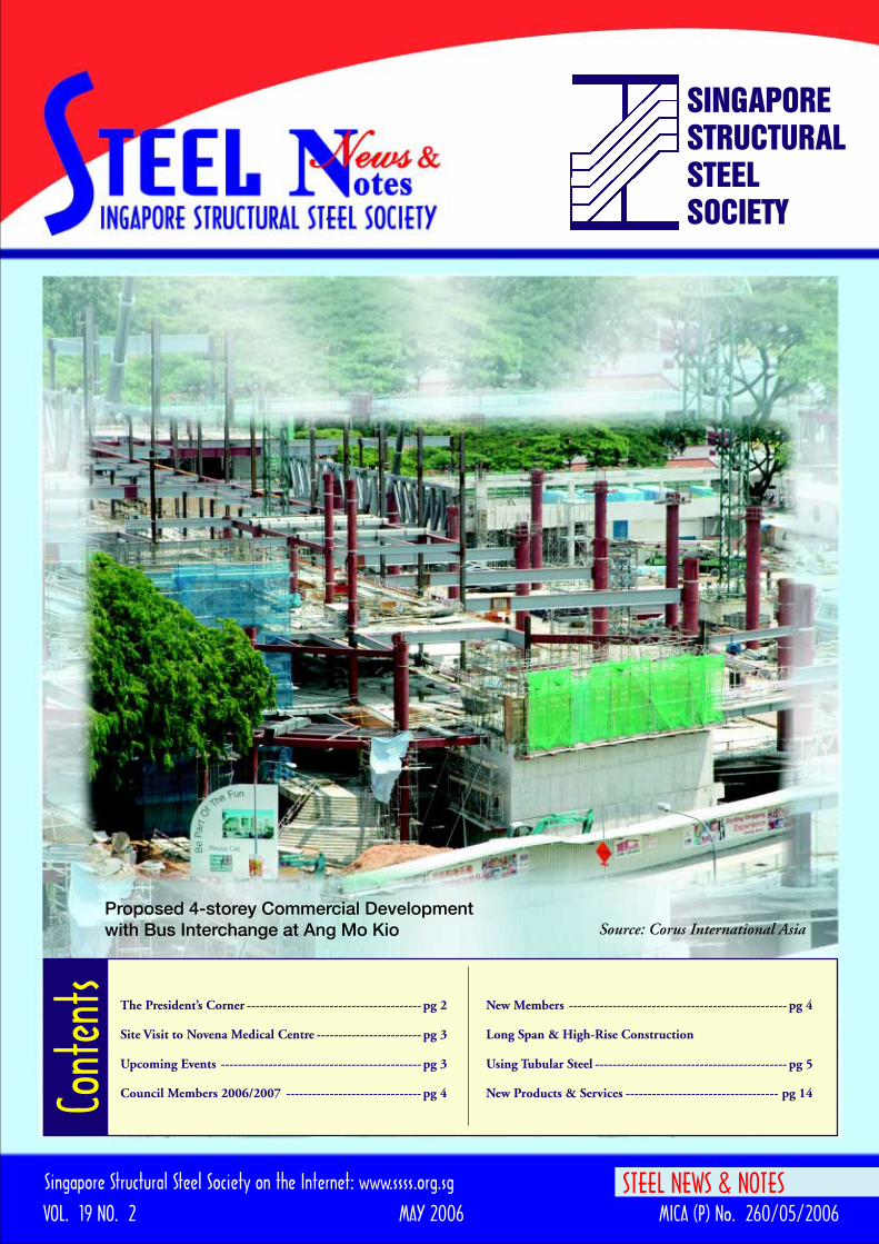
Proposed 4-storey Commercial Developmentwith Bus Interchange at Ang Mo Kio Source: Corus International Asia
2
The President’s CornerDear fellow-members,
Constr uct ion work ispicking up again at quite afast pace. With the Ministryof Manpower’s WorkplaceSafety and Health Actjustenacted, there is renewedinterest and concern onsafety at construction sites.This is because the new actrequires all stakeholders to
take greater responsibility and ownership of safetyproblems. There are also heavier penalties for non-compliance with safety regulations. At the same time,BCA is also working towards the legislation of licensingof builders and specialist subcontractors whose workhave an impact on construction safety. This is likely tocome about early next year. The legislation will affectmany of our corporate members -those companiesengaged in steel fabrication, erection and strutting work.
The SSSS has been pro-active in the area of constructionsafety. Our response to safety concerns has been to takeownership of the problem. For the past three years, theSSSS has channeled much of its efforts and resourcesinto raising the capability of the steel sector to deliverquality work more safely. Today, our SSSS SteelFabricators Accreditation Scheme is in place. There arenow close to 40 steel fabricators registered with SSSSwho meet minimum standards stipulated under the fouraccreditation categories. Our Structural SteelSupervisors’ course is now coming to its third run andchurning out engineers and technicians who are trainedand tested to ensure they are capable of supervisingfabrication and erection of structural steelworkeffectively.
SSSS recently met up with the BCA to discuss how theSteel Fabricators Accreditation Scheme and theStructural Steel Supervisors training programme canhelp the construction industry improve safety standardsof steelworks. The BCA has given its support to theseprogrammes. The authority had already advised QPs to
engage only steel fabricators accredited by SSSS forprojects that involve steelwork. It will also be advisingQPs to use qualified supervisors who have gone throughour Structural Steel Supervisors Training programmeto oversee critical steel projects.
We have also been busy with other activities. Watch outfor various events that we have lined up for you:
27 July 2006. We will be hosting a Corporate Members’Night. This will be held at the Samundar Restaurant,Palawan Beach on Sentosa, at 7.00 pm. Members willbe updated on the latest developments in our SteelFabricators Accreditation scheme, Structural SteelSupervisors Training programme and SSSS activities.
24 August 2006 –day. There will be a one-day workshop(9.00am to 5.00pm) on the design of steel connectionsaccording to Euro-code 3. This will be conducted by DrFantisek Wald, visiting NTU Professor at Hotel Phoenix,Orchard Road
24 August 2006 –evening. On the same evening, wewill have our 22nd Annual Lecture and Dinner at TheBelvedere and Mandarin Court, Meritus Mandarin,starting from 7.00 pm. This year our distinguishedspeaker is Lindsay Holland, a director of LindsayHolland Pty Ltd Architects, Melborne, Australia. Thepractice has received design awards on a regular basis,the latest being the 2002 RAIA Desbrowe Annear Awardfor residential buildings and the BHP ‘Use of Steel’award. The speaker will share with us his invaluableexperiences in the design and construction of steel framehouses covering structural systems and architecturaldesign details.
18 October 2006. Our annual SSSS Golf Challenge willbe at the Seletar Golf Club. Once again, we have anopportunity to interact, relax and have fun and at thesame time raise funds for the SSSS scholarship coffers.
I look forward to seeing you at these events. Wishing allof you better business prospects and please, work safely
Warmest Regards,
Tan Tian Chong
STEEL NEWS & NOTES welcomes contributions on any suitable topic relating to steel use and construction. Publication is at thediscretion of the Editor. Views expressed are not necessarily those of the SSSS, the Editor or the Publisher. Although care has beentaken to ensure that all information contained herein is accurate with relation to either matters of fact or accepted practice at the timeof publication, the SSSS and the Editor assume no responsibility for any errors in or misinterpretation of such information or any lossor damage arising from or related to its use. No part of this publication may be reproduced without the permission of the SSSS.
Published by :Singapore Structural Steel Society232A River Valley Road, Singapore 238290Tel: 6735 6255 Fax: 6238 [email protected] www.ssss.org.sg
Printer :Motion Printers & Publications Pte Ltd9003 Tampines Industrial Park #04-134, Singapore 528837Tel: 6783 3493 Fax: 6783 3661 [email protected]

Site Visit to Novena Medical Centre
A site visit to watch the erection of the Mega Truss at Novena
Square 2 was organised by the Singapore Structural Steel
Society for its members on 18 April 2006 at 9.00 am. All
visitors were treated to a sumptuous lunch by the main
contractor at the end of the visit.
The contract involved design, fabrication, supply and
erection of eight mega trusses spanning about 50m and
weighing an average of 200 tons each with the heaviest truss
weighing 240 tons.
The difficult part of the work was to lift the trusses using
heavy lifting strand jacks as the use of heavy cranes for
erection was not feasible in this case. The whole operation
comprised of the following stages:
- Lifting of all fabricated components to the 3rd Storey
working platform.
- Assembling of the components of the trusses horizontally
on the 3rd Storey working platform.
- Pulling of the fitted-up trusses to the required locations
using four horizontal strand jacks.
- Flipping of the trusses from horizontal to vertical position
to the points of lifting using both the vertical lifting jacks
and horizontal pushing jacks.
- Lifting of the trusses using two 200 tons strand jacks.
- Welding of all connecting joints for completion of the
erection of trusses.
Who’s on the job
Consultant: KTP Consultants Pte Ltd
Main Contractor: China Construction (South Pacif ic)
Development Co Pte Ltd
Steelwork Subcontractors: Steel Structure Fabrication &
Erection Engineering Company:
Company of 22nd MCC
Upcoming Events of the Singapore Structural Steel Society
Briefing by the main contractor Mega Truss lifted to position Participants of the site visit
3
Thursday, 24 August 2006 9.00 am to 5.00 pm One day workshop on “Connection Design according toEurocode 3” conducted by Dr Frantisek Wald,visiting NTU Professor, at Hotel Phoenix, Orchard Road.
Thursday, 24 August 2006 7.00 pm 22nd Annual Lecture and Dinner at Meritus Mandarin Hotel,Orchard Road. This year’s distinguished speaker isMr Lindsay Holland , Director of Lindsay Holland Pty LtdArchitects, Melbourne, Australia.
Wednesday, 18 October 2006 Annual SSSS Golf Challenge will be held at Seletar Golf Club.
To participate in any of the above events please contact :The Secretariat, Singapore Structural Steel Society, 232A River Valley Road, Singapore 239290.Tel. 6735 6255, Fax. 6238 6530. Email: [email protected]
Council Members 2006/2007
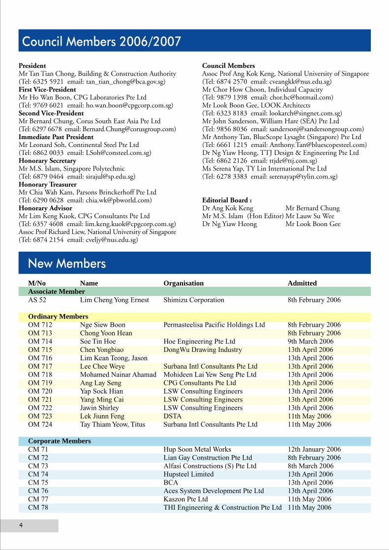
PresidentMr Tan Tian Chong, Building & Construction Authority(Tel: 6325 5921 email: [email protected])First Vice-PresidentMr Ho Wan Boon, CPG Laboratories Pte Ltd(Tel: 9769 6021 email: [email protected])Second Vice-PresidentMr Bernard Chung, Corus South East Asia Pte Ltd(Tel: 6297 6678 email: [email protected])Immediate Past PresidentMr Leonard Soh, Continental Steel Pte Ltd(Tel: 6862 0033 email: [email protected])Honorary SecretaryMr M.S. Islam, Singapore Polytechnic(Tel: 6879 0464 email: [email protected])Honorary TreasurerMr Chia Wah Kam, Parsons Brinckerhoff Pte Ltd(Tel: 6290 0628 email: [email protected])Honorary AdvisorMr Lim Keng Kuok, CPG Consultants Pte Ltd(Tel: 6357 4608 email: [email protected])Assoc Prof Richard Liew, National University of Singapore(Tel: 6874 2154 email: [email protected])
Council MembersAssoc Prof Ang Kok Keng, National University of Singapore(Tel: 6874 2570 email: [email protected])Mr Chor How Choon, Individual Capacity(Tel: 9879 1398 email: [email protected])Mr Look Boon Gee, LOOK Architects(Tel: 6323 8183 email: [email protected])Mr John Sanderson, William Hare (SEA) Pte Ltd(Tel: 9856 8036 email: [email protected])Mr Anthony Tan, BlueScope Lysaght (Singapore) Pte Ltd(Tel: 6661 1215 email: [email protected])Dr Ng Yiaw Heong, TTJ Design & Engineering Pte Ltd(Tel: 6862 2126 email: [email protected])Ms Serena Yap, TY Lin International Pte Ltd(Tel: 6278 3383 email: [email protected])
Editorial Board :Dr Ang Kok Keng Mr Bernard ChungMr M.S. Islam (Hon Editor) Mr Lauw Su WeeDr Ng Yiaw Heong Mr Look Boon Gee
New MembersM/No Name Organisation AdmittedAssociate MemberAS 52 Lim Cheng Yong Ernest Shimizu Corporation 8th February 2006
Ordinary MembersOM 712 Nge Siew Boon Permasteelisa Pacific Holdings Ltd 8th February 2006OM 713 Chong Yoon Hean 8th February 2006OM 714 Soe Tin Hoe Hoe Engineering Pte Ltd 9th March 2006OM 715 Chen Yongbiao DongWu Drawing Industry 13th April 2006OM 716 Lim Kean Teong, Jason 13th April 2006OM 717 Lee Chee Weye Surbana Intl Consultants Pte Ltd 13th April 2006OM 718 Mohamed Nainar Ahamad Mohideen Lai Yew Seng Pte Ltd 13th April 2006OM 719 Ang Lay Seng CPG Consultants Pte Ltd 13th April 2006OM 720 Yap Sock Hian LSW Consulting Engineers 13th April 2006OM 721 Yang Ming Cai LSW Consulting Engineers 13th April 2006OM 722 Jawin Shirley LSW Consulting Engineers 13th April 2006OM 723 Lek Jiunn Feng DSTA 11th May 2006OM 724 Tay Thiam Yeow, Titus Surbana Intl Consultants Pte Ltd 11th May 2006
Corporate MembersCM 71 Hup Soon Metal Works 12th January 2006CM 72 Lian Gay Construction Pte Ltd 8th February 2006CM 73 Alfasi Constructions (S) Pte Ltd 8th March 2006CM 74 Hupsteel Limited 13th April 2006CM 75 BCA 13th April 2006CM 76 Aces System Development Pte Ltd 13th April 2006CM 77 Kaszon Pte Ltd 11th May 2006CM 78 THI Engineering & Construction Pte Ltd 11th May 2006
4

Long Span & High-Rise Construction Using Tubular Steel
ABSTRACTThis paper presents the design challenges and recent innovations, and discusses the construction issues related to multistoreysteel buildings and large span structures involving tubular sections. The basic features of tubular steel design, which becomesmore popular for its structural efficiency and aesthetic appearance, are explained. Special features of prominent steel buildingsand large span tubular roof structures are highlighted. The advantages of using steel-concrete composite systems for multistoreyconstruction are emphasized. The combined use of concrete cores, steel frames and composite floors to form an integratedsystem is recommended for buildability and robustness performance in accident limit states design. Greater emphasis isplaced on collaboration between designers, suppliers, fabricators and contractors to exploit the advantages of real-worldmodeling through advanced analysis and 3-D steel detailing. From design to practice, this paper offers some new pointersfor design and construction of multi-storey and multi-functional facilities using tubular sections. It concludes that tubularsteel is the preferred choice for lightweight, long span and fast track construction.
Keywords: Tubular construction; composite design; computer modeling; large span structures; multistory buildings; spaceframes; steel roofs, tubular joints
1. CONSTRUCTION OF STEEL STRUCTURES BY TUBULAR SECTIONThere are several reasons for the favorable use of tubular structural steel. The first is to act as columns in multi-storeybuilding. Tubular column could offer concrete in-filled option compared to open section. Beside designed as an efficientcomposite column, this option is also able to fulfill fire protection requirements easily. Secondly, tubular steel often offerlighter weight in designing as compression member compared to open section. The section properties to resist compressionforce of tubular section are always better than open section for the same amount of steel weight. Therefore, tubular section isfrequently used in space frames and trusses. Lighter truss or frame would enable a fast and speedy construction because it iseasier to handle by craneage at construction site. Thirdly, tubular section could provide the same external dimension throughoutthe same member by varying the thickness internally, which is unable to achieve by using open section. This characteristic isessential to save the steel weight without sacrificed the aesthetic appearance. Lastly, similar to other steel construction, atypical steel building can be constructed at least 20% less time than it takes to construct a conventional reinforced concretebuilding (Liew, 2001a). Steel modules and components may be prefabricated in the factory and assembled at the site. Thisallows better quality control by adopting a manufacturing route with fully- or semi-automatic production. Fabrication canalso commence even before foundation work begins. Structural steelwork construction does not require a huge storage spaceon site. Prefabrication of two- to three-floors can be carried out off site and delivered as and when the site is ready. This isan important factor for buildings found in the urban city where the construction site is congested and the access is limited.Besides, steel construction encourages the use of labour-efficient design requiring higher skills than the conventional reinforcedconcrete construction. It allows for greater degree of automation, better control of product quality and relies less on unskilledworkers. This is also in line with the trend towards high-quality construction work, improved labour productivity throughautomation and the development of a skilled workforce.
2. PRINCIPLES OF STEEL DESIGN – 3S APPROACHThe designer should first consider external factors such as soil condition, access and storage at the site, availability ofresources, skills and technology, sequence of operations etc, to determine the most appropriate building system to be used.He can then apply the 3S principles of Standardization, Simplicity and Single integrated elements to achieve an efficiencydesign.Standardization refers to the repetition of grids, sizes of components and connection details. A repeated grid layout, forexample, will facilitate faster construction whether metal decking or precast slabs are used. Similarly, columns or externalcladdings of repeated sizes will reduce the number of changes of member sizes and connection details which will greatlyenhance the speed of fabrication and construction.
J Y Richard LiewDepartment of Civil Engineering, National University of Singapore,
Email: [email protected]
5
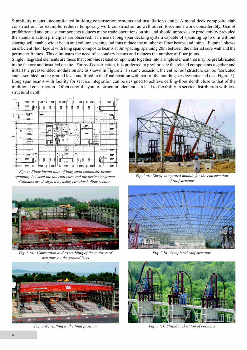
Simplicity means uncomplicated building construction systems and installation details. A metal deck composite slabconstruction, for example, reduces temporary work construction as well as reinforcement work considerably. Use ofprefabricated and precast components reduces many trade operations on site and should improve site productivity providedthe standardization principles are observed. The use of long span decking system capable of spanning up to 6 m withoutshoring will enable wider beam and column spacing and thus reduce the number of floor beams and joints. Figure 1 showsan efficient floor layout with long span composite beams at 3m spacing, spanning 20m between the internal core wall and theperimeter frames. This eliminates the need of secondary beams and reduces the number of floor joints.Single integrated elements are those that combine related components together into a single element that may be prefabricatedin the factory and installed on site. For roof construction, it is preferred to prefabricate the related components together andinstall the preassembled module on site as shown in Figure 2. In some occasion, the entire roof structure can be fabricatedand assembled on the ground level and lifted to the final position with part of the building services attached (see Figure 3).Long span beams with facility for service integration can be designed to achieve ceiling-floor depth close to that of thetraditional construction. Often,careful layout of structural element can lead to flexibility in service distribution with lessstructural depth.
Fig. 1: Floor layout plan of long span composite beamsspanning between the internal core and the perimeter frame.
Columns are designed by using circular hollow section.
Fig. 2(a): Single integrated module for the constructionof roof structure
Fig. 2(b): Completed roof structureFig. 3 (a): Fabrication and assembling of the entire roofstructure on the ground level
Fig. 3 (b): Lifting to the final position Fig. 3 (c): Strand jack at top of columns
6
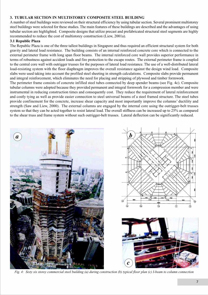
3. TUBULAR SECTION IN MULTISTOREY COMPOSITE STEEL BUILDINGA number of steel buildings were reviewed on their structural efficiency by using tubular section. Several prominent multistoreysteel buildings were selected for these studies. The main features of these buildings are described and the advantages of usingtubular section are highlighted. Composite designs that utilize precast and prefabricated structural steel segments are highlyrecommended to reduce the cost of multistorey construction (Liew, 2001a).3.1 Republic PlazaThe Republic Plaza is one of the three tallest buildings in Singapore and thus required an efficient structural system for bothgravity and lateral load resistance. The building consists of an internal reinforced concrete core which is connected to theexternal perimeter frame with long span floor beams. The internal reinforced core wall provides superior performance interms of robustness against accident loads and fire protection to the escape routes. The external perimeter frame is coupledto the central core wall with outrigger trusses for the purposes of lateral load resistance. The use of a well-distributed lateralload-resisting system with the floor diaphragm improves the overall resistance against the design wind load. Compositeslabs were used taking into account the profiled steel sheeting in strength calculations. Composite slabs provide permanentand integral reinforcement, which eliminates the need for placing and stripping of plywood and timber formwork.The perimeter frame consists of concrete infilled steel tubes connected by deep spender beams (see Fig. 4c). Compositetubular columns were adopted because they provided permanent and integral formwork for a compression member and wereinstrumental in reducing construction times and consequently cost. They reduce the requirement of lateral reinforcementand costly tying as well as provide easier connection to steel universal beams of a steel framed structure. The steel tubesprovide confinement for the concrete, increase shear capacity and most importantly improve the columns’ ductility andstrength (Saw and Liew, 2000). The external columns are engaged by the internal core using the outrigger-belt trussessystem so that they can be acted together to resist lateral load. The overall stiffness can be increased up to 25% as comparedto the shear truss and frame system without such outrigger-belt trusses. Lateral deflection can be significantly reduced.
Fig. 4: Sixty six storey commercial steel building (a) during construction (b) typical floor plan (c) I-beam to column connection
a b
c
7
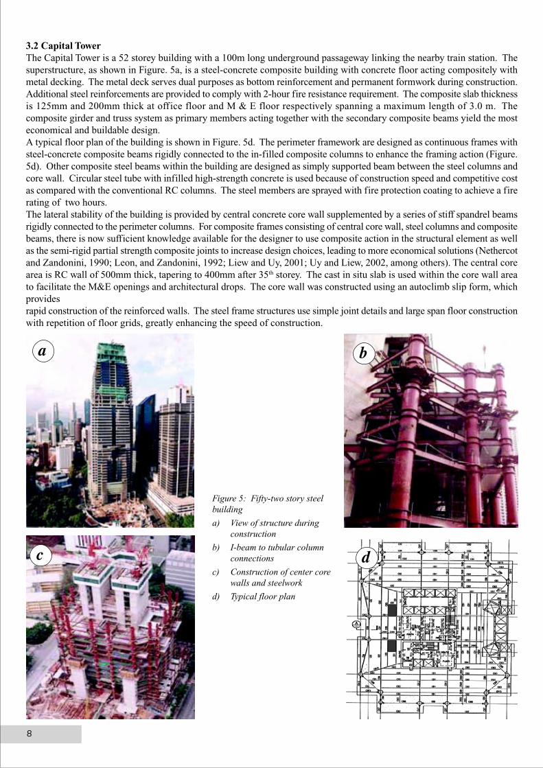
3.2 Capital TowerThe Capital Tower is a 52 storey building with a 100m long underground passageway linking the nearby train station. Thesuperstructure, as shown in Figure. 5a, is a steel-concrete composite building with concrete floor acting compositely withmetal decking. The metal deck serves dual purposes as bottom reinforcement and permanent formwork during construction.Additional steel reinforcements are provided to comply with 2-hour fire resistance requirement. The composite slab thicknessis 125mm and 200mm thick at office floor and M & E floor respectively spanning a maximum length of 3.0 m. Thecomposite girder and truss system as primary members acting together with the secondary composite beams yield the mosteconomical and buildable design.A typical floor plan of the building is shown in Figure. 5d. The perimeter framework are designed as continuous frames withsteel-concrete composite beams rigidly connected to the in-filled composite columns to enhance the framing action (Figure.5d). Other composite steel beams within the building are designed as simply supported beam between the steel columns andcore wall. Circular steel tube with infilled high-strength concrete is used because of construction speed and competitive costas compared with the conventional RC columns. The steel members are sprayed with fire protection coating to achieve a firerating of two hours.The lateral stability of the building is provided by central concrete core wall supplemented by a series of stiff spandrel beamsrigidly connected to the perimeter columns. For composite frames consisting of central core wall, steel columns and compositebeams, there is now sufficient knowledge available for the designer to use composite action in the structural element as wellas the semi-rigid partial strength composite joints to increase design choices, leading to more economical solutions (Nethercotand Zandonini, 1990; Leon, and Zandonini, 1992; Liew and Uy, 2001; Uy and Liew, 2002, among others). The central corearea is RC wall of 500mm thick, tapering to 400mm after 35th storey. The cast in situ slab is used within the core wall areato facilitate the M&E openings and architectural drops. The core wall was constructed using an autoclimb slip form, whichprovidesrapid construction of the reinforced walls. The steel frame structures use simple joint details and large span floor constructionwith repetition of floor grids, greatly enhancing the speed of construction.
Figure 5: Fifty-two story steelbuilding
a) View of structure duringconstruction
b) I-beam to tubular columnconnections
c) Construction of center corewalls and steelwork
d) Typical floor plan
a b
c d
8
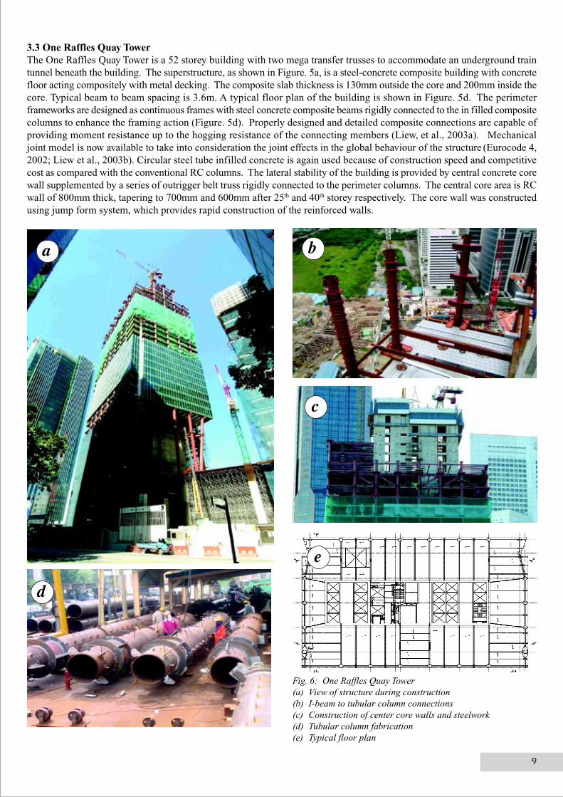
3.3 One Raffles Quay TowerThe One Raffles Quay Tower is a 52 storey building with two mega transfer trusses to accommodate an underground traintunnel beneath the building. The superstructure, as shown in Figure. 5a, is a steel-concrete composite building with concretefloor acting compositely with metal decking. The composite slab thickness is 130mm outside the core and 200mm inside thecore. Typical beam to beam spacing is 3.6m. A typical floor plan of the building is shown in Figure. 5d. The perimeterframeworks are designed as continuous frames with steel concrete composite beams rigidly connected to the in filled compositecolumns to enhance the framing action (Figure. 5d). Properly designed and detailed composite connections are capable ofproviding moment resistance up to the hogging resistance of the connecting members (Liew, et al., 2003a). Mechanicaljoint model is now available to take into consideration the joint effects in the global behaviour of the structure (Eurocode 4,2002; Liew et al., 2003b). Circular steel tube infilled concrete is again used because of construction speed and competitivecost as compared with the conventional RC columns. The lateral stability of the building is provided by central concrete corewall supplemented by a series of outrigger belt truss rigidly connected to the perimeter columns. The central core area is RCwall of 800mm thick, tapering to 700mm and 600mm after 25th and 40th storey respectively. The core wall was constructedusing jump form system, which provides rapid construction of the reinforced walls.
Fig. 6: One Raffles Quay Tower(a) View of structure during construction(b) I-beam to tubular column connections(c) Construction of center core walls and steelwork(d) Tubular column fabrication(e) Typical floor plan
a b
c
d
e
9
4 TUBULAR SECTION IN SPACE FRAME STRUCTURESThe critical factor in the construction of space frame with a large number of interconnected parts is the dimensional tolerancethat can be achieved during the installation. The tolerance of individual parts depends on the method used to connectindividual members. Hence the buildability of a space frame structure would very much depend on the type of joints adoptedand the erection method. Tubular section is usually used to provide a simple connection.4.1 Joints for Space FramesBolted joints are often preferred as most of the prefabrication works can be done in the factory in a controlled environmentthat helps to improve quality. The joints are repetitive, mass produced, simple to fabricate and able to transfer all memberforces meeting at the nodes. Figure 7 shows a typical ball joint connector in which members with threaded ends are connectedto a steel spherical node drilled and tapped to accept up to 18 members. Such nodes enable the axes of all members passthrough the centre of the connector, eliminating eccentricity loading at the joint. Figure. 7(f) show a prefabricated joint withbeam stubs pre-welded to the joint and the members are field bolted to form a three-dimensional structure.Welded joints for tubular section such as those shown in Figures. 7b, 7c and 7e have an advantage of producing structureswith greater rigidity and hence reducing deflection and vibration. They are often use for large span construction. The rigidlyconnected tubular members can resist higher buckling loads as compared to pin-connected members as shown in Figure. 7a.However, site welding increases the erection time and requires higher-skilled workers. In the fabrication of tubular spaceframe structure, it is essential to keep the amount of fabrication and profiling of tube ends to a minimum. Therefore, manyforms of “rigid” connectors were introduced to allow a direct welding of the tube to the connector. Such connectors may bein the form of cylinder with or without fin-plate as shown in Figures. 7b and 7e, or spherical ball joint with external diaphragmstiffener as in Figure. 7c. But the additional of nodes and connectors often add to the final cost and weight of the structure.The increasing use of 3-D steel detailing software would enable full mock up of the structure to be done on the computer, andthe fabrication is controlled by the software using an automated process. This would increase the accuracy of fabrication andreduces the tolerance required at site. Direct welding of tubular members without any connectors becomes a possiblealternative for fabricators who have acquired the high-end skills and equipment to perform such complex task. However, itshould be realized that tubular joints may exhibit some degree of flexibilities under the actions of axial force and moment asshown in Figure. 7(g). The joint flexibility may be modeled using axial and rotational springs as shown in Figure. 7(h) so thata more realistic estimation of the frame responses can be obtained and their effects are accounted for in design.4.2 Erection of Space FramesThe main considerations here are the construction time and safety for the worker. The three basic erection techniques forspace frames are:• Piece-by-piece Erection: Individual structural elements are lifted and assembled, piece-by-piece, in the air.
This procedure is usually tedious and time consuming. The partially completed structure may be unstable andtemporary propping is needed. Extensive working platform is needed for such work to be carried out. Longertime is required because of the large number of components to be lifted. Proper planning is required to ensurespeedy erection. Finally, it is diff icult to control the dimensional accuracy of the individual component.
• Module Erection: The structure is divided into a number of modules. Individual modules are assembled onground, and they are lifted and connected in the final position. Module erection has more advantages comparedto piece-by-piece erection. This is because the number of joints for assembly in the final position is reducedand it is much easier to assemble the individual members on the ground to form a module compared to thesame work done in the air. It is also easier to control the dimensional accuracy of the constructed componentson ground. An example of module construction is shown in Figure. 2.
• Lift-up Method: The structure may be fabricated in segments, assembled close to the ground level, and thenlifted to f inal height using strand jacks mounted on specially design jacking towers strategically positioned toprovide even distribution of the supported weight. This method is particularly suitable for the construction oflarge-span roof structures. The lifting requires synchronous movement of all lift points. This can be achievedby hydraulic pump, feeding the same quantity of oil into each lifting unit. The lift points are monitored by acentral console unit to ensure synchronous movements. An example of lifting the entire roof structure fromthe ground level to its f inal position is shown in Figure. 3.
10
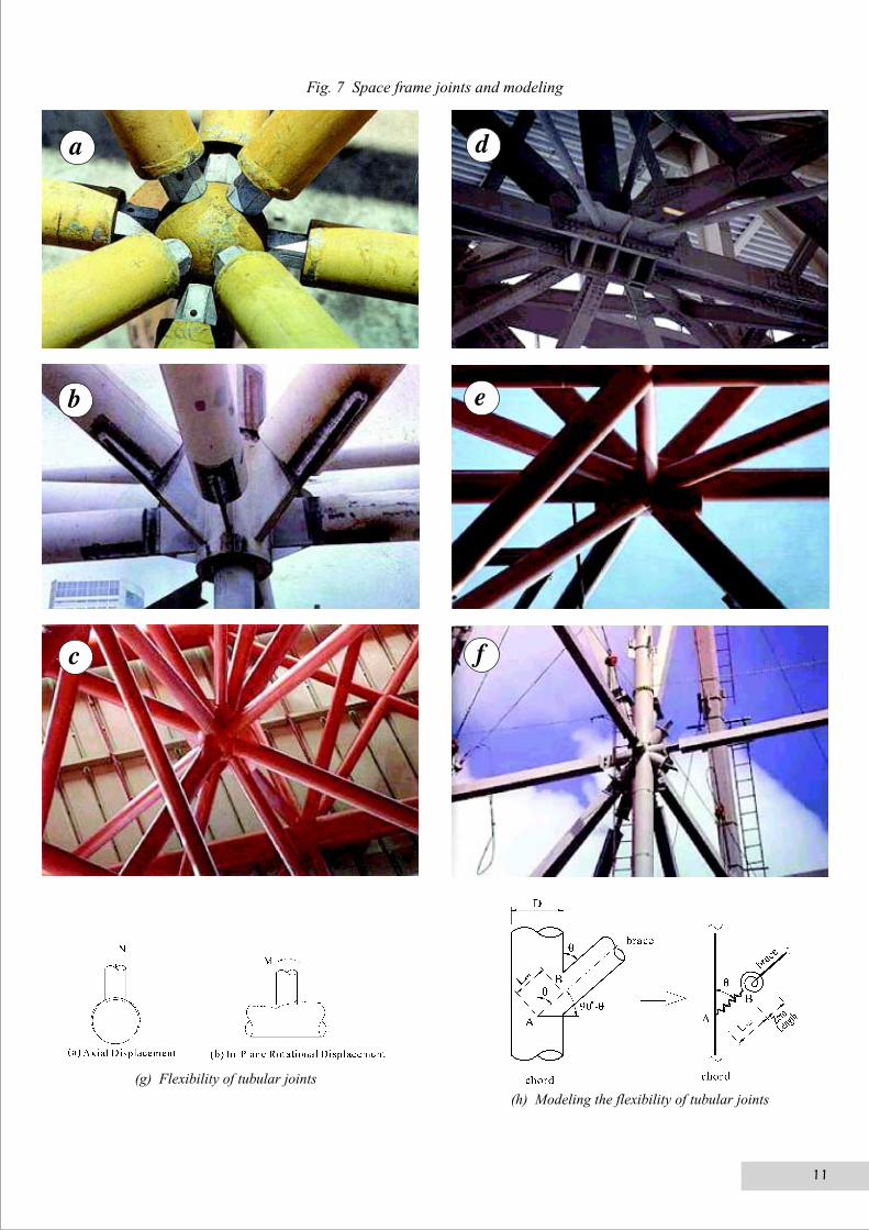
Fig. 7 Space frame joints and modeling
(g) Flexibility of tubular joints
(h) Modeling the flexibility of tubular joints
a d
b e
c f
11
12
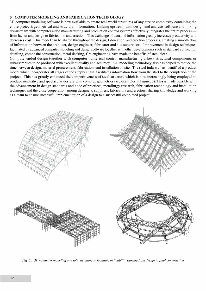
5 COMPUTER MODELING AND FABRICATION TECHNOLOGY3D computer modeling software is now available to create real-world structures of any size or complexity containing theentire project’s geometrical and structural information. Linking upstream with design and analysis software and linkingdownstream with computer aided manufacturing and production control systems effectively integrates the entire process —from layout and design to fabrication and erection. This exchange of data and information greatly increases productivity anddecreases cost. This model can be shared throughout the design, fabrication, and erection processes, creating a smooth flowof information between the architect, design engineer, fabricator and site supervisor. Improvement in design techniquesfacilitated by advanced computer modeling and design software together with other developments such as standard connectiondetailing, composite construction, metal decking, fire engineering have made the benefits of steel clear.Computer-aided design together with computer numerical control manufacturing allows structural components orsubassemblies to be produced with excellent quality and accuracy. 3-D modeling technology also has helped to reduce thetime between design, material procurement, fabrication, and installation on site. The steel industry has identified a productmodel which incorporates all stages of the supply chain, facilitates information flow from the start to the completion of theproject. This has greatly enhanced the competitiveness of steel structure which is now increasingly being employed toproduce innovative and spectacular designs with complex geometries (see examples in Figure. 8). This is made possible withthe advancement in design standards and code of practices, metallurgy research, fabrication technology and installationtechnique, and the close cooperation among designers, suppliers, fabricators and erectors, sharing knowledge and workingas a team to ensure successful implementation of a design to a successful completed project.
Fig. 8 : 3D computer modeling and joint detailing to facilitate buildability starting from design to final construction
6. CONCLUSIONSSeveral prominent steel-composite multistorey buildings constructed in Singapore are described. The main features of thesebuildings were discussed and the advantages of using tubular section were highlighted. Composite designs that utilizeprecast and prefabricated structural steel segments are highly recommended to reduce the cost of multistory construction. Itensures buildability, good quality, shorter construction period, less manpower and wastes, and higher site productivity. Themain features of welded and bolted space frame systems were described together with their buildability in terms of fabrication,design and erection methods. Advanced analysis software together with 3-D steel detailing and modeling allows a smoothflow of information between the architect, design engineer, fabricator and site supervisor. Advances in computing capabilitieshas led to new understanding of full 3-D steel structural behaviour in fire, which enables substantial savings of time spent onsite. A successful implementation of a large steel construction project requires a good balance to be sought between buildability,quality, construction time, material usage and wastage and labour productivity. The use of advanced technology has acceleratedthe adoption of a number of innovations which lead to an overall improvement of productivity in steel construction.Steel structure especially tubular section is now increasingly being employed to produce innovative and spectacular architecturaldesigns with complex geometrical profiles. This is made possible with the advancement in design expertise, metallurgyresearch, fabrication technology and erection technique, and more importantly, the close cooperation and commitment ofdesigners, suppliers, fabricators and erectors, sharing knowledge and working as a team to ensure successful transformationof an innovative design to a successful completed project of architectural and structural marvel.
ACKNOWLEDGEMENTThe author would like to thank the individuals and organizations for their consent to use the information from their projects.In particular, the help from the Singapore Structural Steel Society, the Building Construction Authority of Singapore, andthe support from Continental Steel Pte Ltd, Bluescope Lysaght (S) Pte Ltd, Corus International Asia, TTJ Design andEngineering Pte Ltd and Yongnam Holdings Ltd are gratefully acknowledged.
ReferenceS
Brain, U. and Liew, J. Y. R. (2002), Composite steel-concrete structures, Chapter 51 of The Civil Engineering Handbook, 2nd
Edition, Editors: W.F. Chen and J.Y.R. Liew, United States: CRC Press, Boca Raton, 51-1 to 51-62).Eurocode 4 (2002), PrEn 1994-1-1 Design of Composite Steel and Concrete Structures, Part 1.1 General Rules and Rules,
European Committee for Standardization.Leon, R. T. and Zandonini, R. (1992), “Composite connection”, Chapter 4.4, Constructional Steel Design – An International
Guide, Editors: Dowling, et al., Elsevier, England, 501-522.Leon, R. T, Hoffman, J. and Staeger, T. (1996), Design of Partially–Restrained Composite Connections, AISC Design Guide
9, American Institute of Steel Construction, Chicago.Liew, J. Y. R. (2001a), A resource book for structural steel design and construction, SSSS/BCA Joint Publication, Singapore
Structural Steel Society, 83pp.Liew, J. Y. R. (2001b), “State-of-the-art of advanced analysis of steel and composite frames”, Int. J Steel and Composite
Structures, Techno-Press, Vol. 1, No. 3, 341-254.Liew J. Y. R. and Uy, B. (2001), “Advanced analysis of composite frames”, Progress in Structural Engineering and Material,
John Wiley, UK, 2001, 3(2), 159-169.Liew, J. Y. R, Chen, H, and Shanmugam, N. E. (2001), “Nonlinear analysis of steel frames with composite beams”, J
Structural Engineering, ASCE, 127(2), 361-370.Liew, J. Y. R, Teo, T. H. and Shanmugam, N E (2003), “Composite joints subject to reversal of loading – Part I: Experimental
Study; Part II Analytical Assessment”, Journal of Constructional Steel Research, Vol. 60, Issue 2, 221-268.Nethercot, D. A. and Zandonini, R. (1990), “Methods of prediction of joint behaviour: Beam-to-column connections”, In
Structural Connections: Stability and Strength edited by R. Narayanan, Elsevier Applied Science, London, Chap. 2, 22-62.Saw, H. S. and Liew, J. Y. R. (2000), “Assessment of current methods for the design of composite columns in buildings”,
Journal of Constructional Steel Research, Elsevier, UK, Vol. 53, No. 2 (pp. 121-147).
13
New Products & Services
The Steel Structure Fabrication & Erection Engineering Company(hereafter abbreviated as “SSFEE”), a subsidiary of China 22nd
Metallurgical Construction Corporation (abbreviated as China 22nd
MCC), is mainly devoting to steel structural engineering,fabrication and erection. As a specialized company, SSFEE hasacquired the Grade One qualification certification in steel structureconstruction, and the Second Class in engineering design. Now,SSFEE has employees 1,730, including 1,300 technicalprofessionals, and 68 designers for steel structure seconddesigning.SSFEE annual capacity is over 100,000 tons in steel structurefabrication and erection, involved scopes including metallurgy,construction material, chemical industry, civil engineering, citypublic service etc.In the whole metallurgical construction industry, SSFEE is thefirst company to have been awarded “The integrated managementsystem certification for Quality, Environment and Occupationalsafety and health”.SSFEE is located in the Industrial Park of China 22nd MCC, whichis a large modern industrial base, focusing on steel productfabrication for industrial and civil construction. The total area is370000m2, 50000m2 modernized workshop equipped advancedprocessing machines and technique. The Industrial Park owns aseries of steel structure production lines, such as heavy H steel,light H steel, box structure, pipe network structure, decking plateetc, to meet various requirements. Furthermore, China 22nd MCChas introduced into a whole box steel structure production lineand relevant technology from Japan, which is the most advancedin the world. The automatic production-line adopted for thewelding of box steel girder and steel column units combination isconsidered to be the cutting-edge technology at home as well asabroad in the said industry.SSFEE has since expanded into the market of Singapore and iscurrently completing the Square 2 and IKEA Tampines. It is thecompany’s policy to continue pursuing new opportunities inSingapore as well as the regional markets and at the same time,forming strategic alliances with potential partners to enhance ourcompetitive edge.FOR THE MOST VIABLE & CREATIVE SOLUTIONS INSTEEL, KINDLY CONTACT US AS FOLLOWS:1. Li Wen Feng (H/P:90839780)2. Chor How Choon (H/P:98791398)
Steel Structure Fabrication& Erection EngineeringCompany of 22nd MCC
Novena Medical Centre14
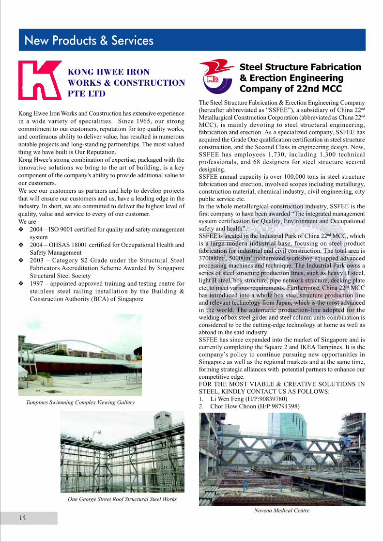
KONG HWEE IRONWORKS & CONSTRUCTIONPTE LTD
Kong Hwee Iron Works and Construction has extensive experiencein a wide variety of specialities. Since 1965, our strongcommitment to our customers, reputation for top quality works,and continuous ability to deliver value, has resulted in numerousnotable projects and long-standing partnerships. The most valuedthing we have built is Our Reputation.Kong Hwee’s strong combination of expertise, packaged with theinnovative solutions we bring to the art of building, is a keycomponent of the company’s ability to provide additional value toour customers.We see our customers as partners and help to develop projectsthat will ensure our customers and us, have a leading edge in theindustry. In short, we are committed to deliver the highest level ofquality, value and service to every of our customer.We are❖ 2004 – ISO 9001 certified for quality and safety management
system❖ 2004 – OHSAS 18001 certified for Occupational Health and
Safety Management❖ 2003 – Category S2 Grade under the Structural Steel
Fabricators Accreditation Scheme Awarded by SingaporeStructural Steel Society
❖ 1997 – appointed approved training and testing centre forstainless steel railing installation by the Building &Construction Authority (BCA) of Singapore
Tampines Swimming Complex Viewing Gallery
One George Street Roof Structural Steel Works
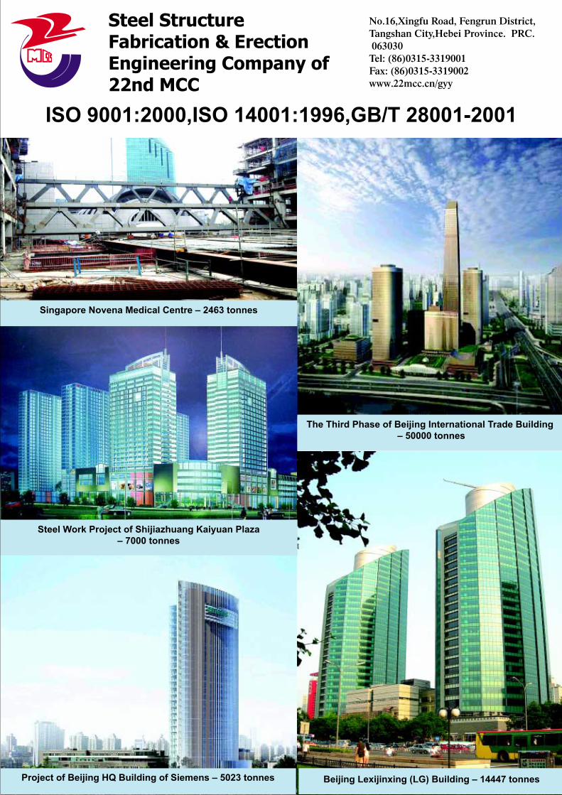
Steel StructureFabrication & ErectionEngineering Company of22nd MCC
No.16,Xingfu Road, Fengrun District,Tangshan City,Hebei Province. PRC. 063030Tel: (86)0315-3319001Fax: (86)0315-3319002www.22mcc.cn/gyy
ISO 9001:2000,ISO 14001:1996,GB/T 28001-2001
Singapore Novena Medical Centre – 2463 tonnes
The Third Phase of Beijing International Trade Building – 50000 tonnes
Steel Work Project of Shijiazhuang Kaiyuan Plaza– 7000 tonnes
Project of Beijing HQ Building of Siemens – 5023 tonnes Beijing Lexijinxing (LG) Building – 14447 tonnes