Embed Size (px)
Citation preview

siemens.com/marine
SINAVY PEM Fuel CellsFor Submarines

Contents
Introduction 3
PEM Fuel Cells: Function and design
6
PEM Fuel Cells: Modules and power plant
8
Outlook 11
Fuel cells enable the direct generation of electric power from hydrogen and oxygen with significantly higher effi-ciency, with noiseless operation and without pollutant emissions compared with conventional combustion engines.
2

3

Submarine
Air-independent propulsion (PEM FC)
Space shuttle
Air-independent power supply (PEM FC)
Storage system for regenerative energies
Siemens Electrolyzer (PEM FC)
Railroad
Electrical propulsion (SOFC, PEM FC)
Gas tanker
Electrical propulsion (SOFC, PEM FC)
Bus
Emission-free and noiseless operation (PEM FC)
Delivery trucks
Emission-free and noiseless operation (PEM FC)
H2O2 H2/air
Reformer gas/air
Reformer gas/air
Fuel Cell power plants
Present and future applications
Fig. 1: Possible applications for fuel cell power plants
Application potential
Decentral power plants
Grid-independent operation (SOFC, PEM FC)
Freighter
Emergency power supply (PEM FC)
Passenger car
Emission-free and energy- efficient operation (PEM FC)
4

In addition to these basic advantages, the fuel cell with a solid, ion-conducting, polymeric membrane (polymer electrolyte membrane – PEM) has more positive properties:
• Quick switch-on, switch-off behavior• Low voltage degradation and long service life• Favorable load and temperature-cycle behavior• Capability of overload operation • Low operating temperature (80° Celsius)• Absence of a liquid-corrosive electrolyte.
All of these characteristics make the SINAVY PEM Fuel Cell an ideal power unit.
Aboard submarines they show their outstanding advantages over other AIP (air-independent propulsion) systems for conventional submarines. Using oxygen and hydrogen stored in liquid or gaseous form on board as reactants, the only process result besides electricity, waste heat and small amounts of residual gases which are given into the boats atmosphere is process water. This process water can be used for different purposes, such as weight balancing to avoid process-related needs for trim adaptions of the submarine.
Siemens offers two types of SINAVY PEM Fuel Cell modules for your selection – the FCM 34 and the FCM 120.
Submarines of Class 212A (six in the German Navy and four in the Italian Navy) are equipped with FCM 34 modules, which were developed from 1984 at the request of the German Ministry of Defense.
Submarines of Class 214 – operated by the Hellenic Navy, Republic of Korea Navy, Portuguese Navy, and in future by the Turkish Navy – are equipped with FCM 120 modules, which were developed in a later phase. Development work is ongoing either improving existing modules or designing future modules.
Energy
Water
Hydrogen Oxygen
Fig. 2
Operational submarines of Class 209 can be upgraded with an additional fuel-cell power plant during refit, and so acquire the benefits of air-independent propulsion (AIP) at a much lower price than for acquiring a new AIP-sub-marine.
The impressive advantage of the AIP Technology, which is basing on fuel-cells, has been demonstrated on board of submarines of classes 212A, 214, and Dolphin AIP.
5

PEM Fuel Cells: Function and design
A simplified representation of the SINAVY PEM Fuel Cells’ basic function and design is shown in (Fig. 3): the electrochemical element at which the chemical energy is converted into electrical energy is the membrane electrode unit. It consists of the polymer electrolyte, the gas diffusion electrodes with a platinum catalyst and carbon sheets on each side.
After the abstraction of the electrons from hydrogen – they flow from the anode via the electrical load to the cathode – the resulting protons migrate from the anode to the cathode where they combine with oxygen (and the electrons) to form water.
The theoretical voltage of an H2/O2 fuel cell is 1.48 V ( referred to the upper heat value of hydrogen). At zero-load conditions, slightly more than one volt per cell is available.
The cooling units or bipolar plates, in combination with carbon diffusion layers, distribute the reactants uniformly across the area of the cell, conduct the electrons across the stack, remove the heat from the electrodes, and sepa-rate the media from each other.
Figure 4 shows the two core components of a cell with outside dimensions of 400 x 400 mm, as used in FCM 34 modules.
Figure 5 compares the bipolar plate of the FCM 34 modules to the FCM 120. Two cells of the FCM 120 produce about twice the power of one cell of the FCM 34 type with nearly the same active area.
Cooling unit
400
mm
Cooling unitMembrane electrode unit
Fig. 4: Components of cell Fig. 5: Comparison of cells: FCM 34 Type (back), FCM 120 Type (front)
6

The theoretically high development potential in regard to the membrane material is shown in Figure 6. With im-proved materials, the power density can be nearly doubled.
The voltage of a SINAVY PEM Fuel Cell with respect to the operating time is stable, and degradation rates are less than 2 µV/h per cell for FCM 34 module. Significantly lower values were achieved during the operation of a FCM 120.
Hydrogen H2 Oxygen O2
Electrical load 4e⁻
2H2+4e⁻=4H⁺ O2+4e⁻=20⁻ 20⁻+4H⁺=2H2O
Anode Cathode
H⁺
H⁺
H⁺
Product water H2O + O2
Polymer electrolyte
Waste heat
Fig. 3: Functional principle
Fig. 6: Potential output increases by using various electrolytes
Cell Voltage [UC/V]Cell Output
PC/W
Naf 115
Naf 115
Naf 117
Naf 117
Current I/A
1.1
1.0
0.9
0.8
0.7
0.6
0.5
1,000
800
600
400
200
00 500 1,000 1,500
7

PEM Fuel Cells: Modules and power plant
PEM Fuel Cell modulesSiemens has put every effort into integrating the PEM Fuel Cell stack, valves, piping, and sensors as well as the corre-sponding module electronics control and the ancillaries into a single container making the best use of the limited space on board. The ancillaries comprise the equipment for supplying H2, O2, and N2 for reactant humidification, for product water, and waste heat and residual gas removal. The container is filled with N2 inert gas at 3.0 bar abs. to prevent a release of H2 and/or O2 in case of leakages. Thus, the operator can use the PEM Fuel Cell as a working black box without having to care about the processes inside the container.
The PEM Fuel Cell module can be operated at various static and dynamic load currents. Currents below 650 A for FCM 34 modules or below 560 A for FCM 120 modules can be applied in continuous operation. The output power/current characteristics for FCM 34 modules are shown in Figure 7.
For currents above the rated current, the loading time is limited due to insufficient heat removal at these values. Even loads up to double the rated current can be applied for a short time.
At the rated operating point, the overall efficiency is approximately 59 percent with respect to the lower heat value of H2 (LHV). It increases in the part-load range, reaching a maximum of approximately 69 percent at a load factor of some 20 percent of the rated current ( approximately 100 A) (Fig. 8).
The properties of the FCM 34 and FCM 120 modules are listed in the table on page 10.
8

PEM Fuel Cell power plantAppropriate operating conditions for fuel-cell modules are provided for submarine applications by a fuel-cell system in which fuel cell modules are connected
• to the hydrogen and oxygen supply• to disposal units for functions like
– cooling – residual gas – reaction water
• to auxiliary systems for functions like – inert gas drying – degasing for cooling fluid – nitrogen supply – evacuation system
• to the propulsion/ship’s system as to supply it with demanded electrical power
Operator control and visualization of the fuel-cell system are facilitated by the integrated platform management system or directly via the control panel of the fuel-cell system. Figure 9 gives a simplified overview of the AIP system.
The fuel-cell system in its entirety – the complete fuel-cell power plant, especially the supply and disposal systems described above for AIP operation, including spatial and functional integration on board – has been developed by HDW (Howaldtswerke Deutsche Werft AG).
The submarine classes 212A, 214, and Dolphin are equipped with the new fuel-cell power plant by HDW based on SINAVY PEM Fuel Cells modules by Siemens. An AIP system with SINAVY PEM Fuel Cells modules can be added to existing submarines.
140
120
100
80
60
40
20
0
Module output [kW]
0 700 1,400Current [A]
160
180
1,050350
Fig. 7: Performance Data of FCMs Fig. 8: Efficiency of FCM 34 and 120
80
70
60
50
40
30
20
10
0
Efficiency [%/h0]
0 800 1,000200 400 600 1,200Current [A]
FCPP peripheral devices:– oxygen– hydrogen– product water– residual gases– cooling system– evacuation– ...
Boat Main Switch-board
Boat Main Switch-board
FCPP Switchboard 1
FCPP Switchboard
FCM 34
a
b
Converter FCM 120
FCPP Switchboard 2
EMCS
Fig. 9: Two types of fuel-cell power plants (FCPP)
a: fuel-cell battery with FCM 34; direct coupling of FC voltage to boats mains at class 212A submarine
b: fuel-cell battery with FCM 120; coupling via converter at class 214 submarine
EMCS
FCM 34
FCM 120 FCM 34
FCM 120
9
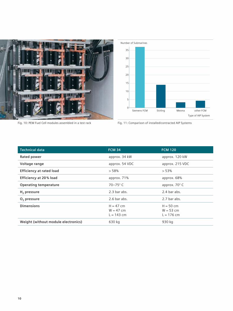
Fig. 11: Comparison of installed/contracted AIP SystemsFig. 10: PEM Fuel Cell modules assembled in a test rack
Technical data FCM 34 FCM120
Rated power approx. 34 kW approx. 120 kW
Voltage range approx. 54 VDC approx. 215 VDC
Efficiency at rated load > 58% > 53%
Efficiencyat20%load approx. 71% approx. 68%
Operating temperature 70–75° C approx. 70° C
H2 pressure 2.3 bar abs. 2.4 bar abs.
O2 pressure 2.6 bar abs. 2.7 bar abs.
Dimensions H = 47 cm W = 47 cm L = 143 cm
H = 50 cm W = 53 cm L = 176 cm
Weight (without module electronics) 630 kg 930 kg
35
30
25
20
15
10
5
0
Number of Submarines
Siemens FCM Stirling Mesma other FCM
Type of AIP System
10

Summary and OutlookSINAVY PEM Fuel Cells modules BZM 34 and BZM120arewell-establishedinthemarket.They have proven their performance and reliability in extensive tests. There is also the possibility to repower and refit operational submarines with an AIP system with SINAVY PEM Fuel Cells modules. The SINAVY PEM Fuel Cells technology’s field of application will be extended, when suitable reformers are available to produce hydrogen from liquid fuels, for example, methanol and diesel. Then, fuel cells may become the sole power source for the submarines of the future. With the ongoing R&D work the SINAVY PEM Fuel Cells modules will be improved conti-nously following the future growing demands of reliability and availability.
11

Published by Siemens AG 2016
Process Industries and Drives Division Marine Lindenplatz 2 20099 Hamburg, Germany
E-mail: [email protected] siemens.com/marine
Article No. VRMS-B10018-00-7600 Printed in Germany Dispo 16600 TH 464-160495 BR 08160.25Subject to changes and errors. The information given in this document only contains general descriptions and/or performance features which may not always specifically reflect those described, or which may undergo modification in the course of further development of the products. The requested performance features are binding only when they are expressly agreed upon in the concluded contract.
Photo source: (©) thyssenkrupp Marine Systems