Embed Size (px)
Citation preview
Getting Started
SINAMICS
Getting Started · 10/2008
SINAMICS S110
s

__________________________________________
Preface
Drive concept
1
Requirements
2
Creating the drive project ONLINE
3
Getting Started
Function Manual
10/2008 6SL3097-4AG10-0BP0
Available from Firmware-Version 4.1
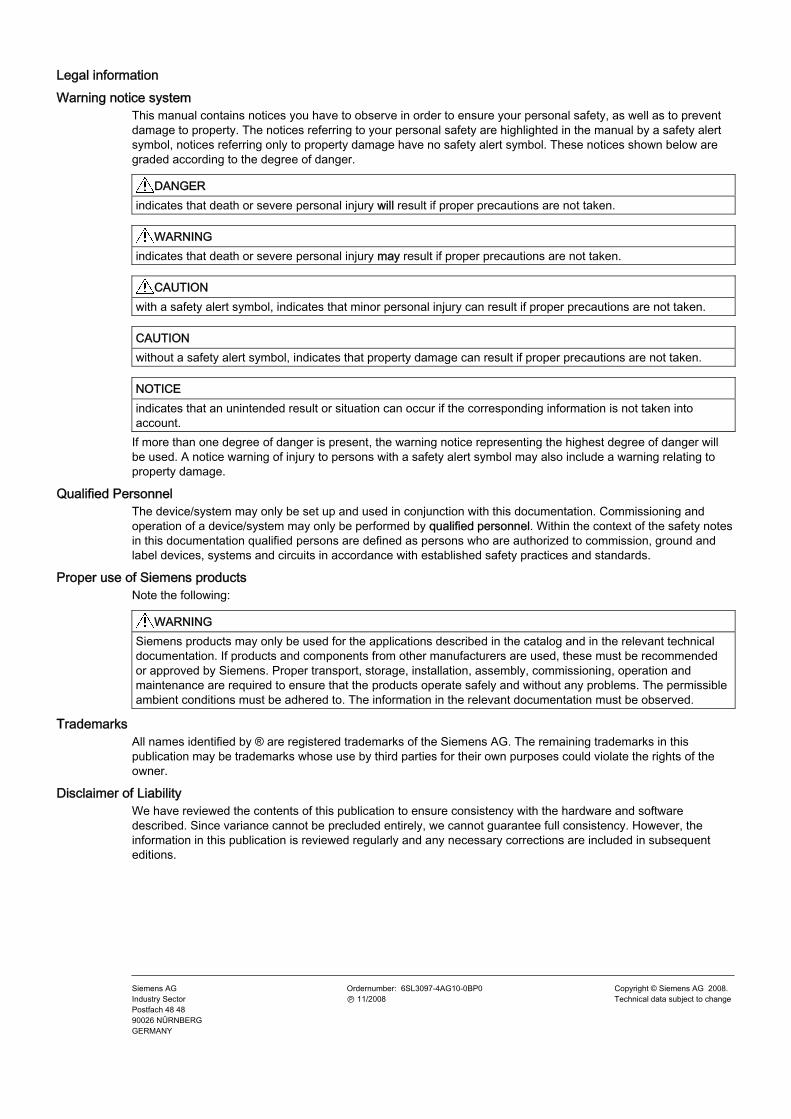
Legal information Warning notice system
This manual contains notices you have to observe in order to ensure your personal safety, as well as to prevent damage to property. The notices referring to your personal safety are highlighted in the manual by a safety alert symbol, notices referring only to property damage have no safety alert symbol. These notices shown below are graded according to the degree of danger.
DANGER indicates that death or severe personal injury will result if proper precautions are not taken.
WARNING indicates that death or severe personal injury may result if proper precautions are not taken.
CAUTION with a safety alert symbol, indicates that minor personal injury can result if proper precautions are not taken.
CAUTION without a safety alert symbol, indicates that property damage can result if proper precautions are not taken.
NOTICE indicates that an unintended result or situation can occur if the corresponding information is not taken into account.
If more than one degree of danger is present, the warning notice representing the highest degree of danger will be used. A notice warning of injury to persons with a safety alert symbol may also include a warning relating to property damage.
Qualified Personnel The device/system may only be set up and used in conjunction with this documentation. Commissioning and operation of a device/system may only be performed by qualified personnel. Within the context of the safety notes in this documentation qualified persons are defined as persons who are authorized to commission, ground and label devices, systems and circuits in accordance with established safety practices and standards.
Proper use of Siemens products Note the following:
WARNING Siemens products may only be used for the applications described in the catalog and in the relevant technical documentation. If products and components from other manufacturers are used, these must be recommended or approved by Siemens. Proper transport, storage, installation, assembly, commissioning, operation and maintenance are required to ensure that the products operate safely and without any problems. The permissible ambient conditions must be adhered to. The information in the relevant documentation must be observed.
Trademarks All names identified by ® are registered trademarks of the Siemens AG. The remaining trademarks in this publication may be trademarks whose use by third parties for their own purposes could violate the rights of the owner.
Disclaimer of Liability We have reviewed the contents of this publication to ensure consistency with the hardware and software described. Since variance cannot be precluded entirely, we cannot guarantee full consistency. However, the information in this publication is reviewed regularly and any necessary corrections are included in subsequent editions.
Siemens AG Industry Sector Postfach 48 48 90026 NÜRNBERG GERMANY
Ordernumber: 6SL3097-4AG10-0BP0 Ⓟ 11/2008
Copyright © Siemens AG 2008. Technical data subject to change
Getting Started Function Manual, 10/2008, 6SL3097-4AG10-0BP0 5
Preface
SINAMICS documentation The SINAMICS documentation is organized in two parts: ● General documentation/Catalogs ● Manufacturer/service documentation At http://www.siemens.com/motioncontrol/docu information is available on the following topics: ● Ordering documentation:
Here you will find the current overview of publications. ● Downloading documentation:
Links to more information for downloading files from Service & Support. ● Researching documentation online.
Information on DOCconCD and direct access to the publications in DOCconWeb. ● Individually compiling documentation on the basis of Siemens contents with the My
Documentation Manager (MDM), refer to http://www.siemens.com/mdm. ● The My Documentation Manager offers you a number of features for compiling your own
machine documentation. Training and FAQs Information on the range of training courses and FAQs (frequently asked questions) are available via the page navigation.
Purpose of the document This documentation is aimed at beginners who want to find out more about the SINAMICS S110 drive system. This document will show you how to configure an S110 drive train within approx. 3 minutes and start the motor.
Internet address for SINAMICS http://www.siemens.com/sinamics.
EC Declaration of Conformity The EC Declaration of Conformity for the EMC Directive can be found at: ● On the Internet:
http://support.automation.siemens.com In the "Search" field, enter the document ID 15257461 and press "Enter".
● At the relevant Siemens office of the I DT MC Business Unit of Siemens AG.
Preface
Getting Started 6 Function Manual, 10/2008, 6SL3097-4AG10-0BP0
Safety notices
DANGER • Commissioning must not start until you have ensured that the machine in which the
components described here are to be installed complies with Directive 98/37/EC. • SINAMICS devices and AC motors may only be commissioned by suitably qualified
personnel. • The personnel must take into account the information provided in the technical customer
documentation for the product, and be familiar with and observe the specified danger and warning notices.
• When electrical equipment and motors are operated, the electrical circuits automatically conduct a dangerous voltage.
• Dangerous mechanical movements are possible during system operations. • All the work carried-out on the electrical machine or system must be carried-out with it in
a no-voltage condition. • SINAMICS devices with AC motors may only be connected to the power supply via an
AC-DC residual-current-operated device with selective switching once verification has been provided that the SINAMICS device is compatible with the residual-current-operated device in accordance with EN 50178, Chapter 5.2.11.2.
WARNING • The successful and safe operation of this equipment and motors is dependent on
professional transport, storage, installation and mounting as well as careful operations , service and maintenance.
• Information and data from the catalogs and quotations also apply to special versions of the equipment and motors.
• In addition to the danger and warning information provided in the technical customer documentation, the applicable national, local, and plant-specific regulations and requirements must be taken into account.
• Only protective extra-low voltages (PELV) that comply with EN60204-1 may be connected to all connections and terminals between 0 and 48 V.
CAUTION • The motors can have surface temperatures of over +80 °C. • This is why temperature-sensitive components, e.g. cables or electronic components
must not be in contact with or attached to the motor. • When connecting up cables, please ensure that they
– are not damaged – are not subject to tensile stress – cannot be touched by rotating components.
Preface
Getting Started Function Manual, 10/2008, 6SL3097-4AG10-0BP0 7
CAUTION • As part of routine tests, SINAMICS devices with AC motors undergo a voltage test in
accordance with EN 50178. Before the voltage test is performed on the electrical equipment of industrial machines to EN 60204-1, Section 19.4, all connectors of SINAMICS equipment must be disconnected/unplugged to prevent the equipment from being damaged.
• Motors should be connected up according to the circuit diagram provided otherwise they may be destroyed.
Note When operated in dry operating areas, SINAMICS equipment with AC motors conforms to low-voltage Directive 73/23/EEC.
CAUTION Electrostatic sensitive devices (ESD) are single components, integrated circuits or devices that can be damaged by electrostatic fields or electrostatic discharges. Regulations for the ESD handling: During the handling of electronic components, pay attention to the grounding of the person, workplace and packaging! Electronic components may be touched by persons only when • these persons are grounded using an ESD bracelet, or • these persons in ESD areas with a conducting floor wear ESD shoes or ESD grounding
straps. Electronic components should be touched only when this is unavoidable. The touching is permitted only on the front panel or on the circuit board edge. Electronic components must not be brought into contact with plastics or clothing made of artificial fibers. Electronic components may only be placed on conducting surfaces (table with ESD coating, conducting ESD foamed material, ESD packing bag, ESD transport container). Electronic components may not be placed near display units, monitors or televisions (minimum distance from the screen > 10 cm). Measurements must only be taken on boards when the measuring instrument is grounded (via protective conductors, for example) or the measuring probe is briefly discharged before measurements are taken with an isolated measuring device (for example, touching a bare metal housing).

Getting Started Function Manual, 10/2008, 6SL3097-4AG10-0BP0 9
Contents
Preface ...................................................................................................................................................... 5 1 Drive concept........................................................................................................................................... 11
1.1 Overview ......................................................................................................................................11 1.2 Components.................................................................................................................................11
2 Requirements .......................................................................................................................................... 13 2.1 Hardware and software components ...........................................................................................13
3 Creating the drive project ONLINE .......................................................................................................... 15 3.1 Creating the drive project ONLINE ..............................................................................................15 3.2 Requirements...............................................................................................................................15 3.3 Creating projects ONLINE ...........................................................................................................16 3.4 Transferring the configuration......................................................................................................20 3.5 Operating the drive with the control panel ...................................................................................23

Getting Started Function Manual, 10/2008, 6SL3097-4AG10-0BP0 11
Drive concept 11.1 Overview
This manual uses an example to demonstrate how to commission a standard drive application comprising a drive configuration with SINAMICS S110, an SMI motor, and the STARTER commissioning tool.
1.2 Components SINAMICS S110 is a modular system that enables you to assemble your drive unit. The key components of the SINAMICS modular system are: ● Control Unit CU305 ● Power Module (line infeed, DC link, and power unit) ● Sensor Module (e.g. encoder) ● SMI motors
Drive concept 1.2 Components
Getting Started 12 Function Manual, 10/2008, 6SL3097-4AG10-0BP0
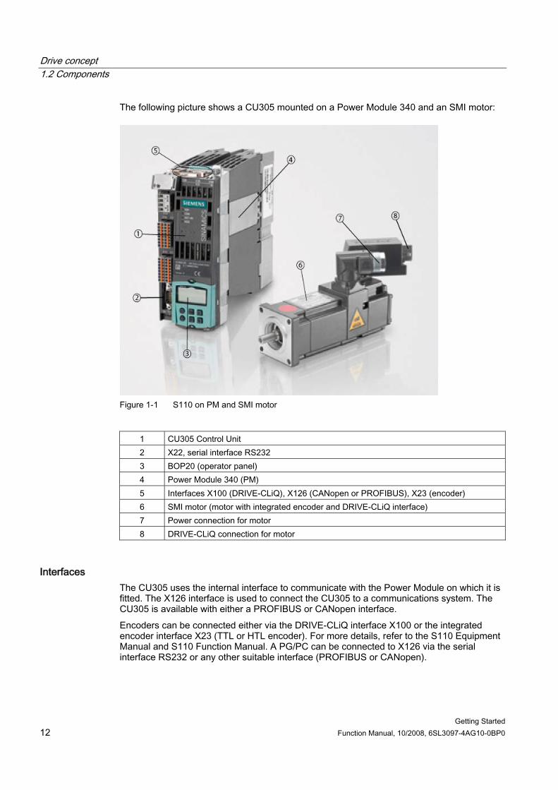
The following picture shows a CU305 mounted on a Power Module 340 and an SMI motor:
Figure 1-1 S110 on PM and SMI motor
1 CU305 Control Unit 2 X22, serial interface RS232 3 BOP20 (operator panel) 4 Power Module 340 (PM) 5 Interfaces X100 (DRIVE-CLiQ), X126 (CANopen or PROFIBUS), X23 (encoder) 6 SMI motor (motor with integrated encoder and DRIVE-CLiQ interface) 7 Power connection for motor 8 DRIVE-CLiQ connection for motor
Interfaces The CU305 uses the internal interface to communicate with the Power Module on which it is fitted. The X126 interface is used to connect the CU305 to a communications system. The CU305 is available with either a PROFIBUS or CANopen interface. Encoders can be connected either via the DRIVE-CLiQ interface X100 or the integrated encoder interface X23 (TTL or HTL encoder). For more details, refer to the S110 Equipment Manual and S110 Function Manual. A PG/PC can be connected to X126 via the serial interface RS232 or any other suitable interface (PROFIBUS or CANopen).
Getting Started Function Manual, 10/2008, 6SL3097-4AG10-0BP0 13
Requirements 22.1 Hardware and software components
The example provided here involves creating a drive train with an SMI motor. The following components are required: ● Control Unit CU305 ● Power Module ● SMI motor (synchronous or induction motor) ● DRIVE-CLiQ cable ● Motor/power cables, optional line filter and line reactor for the Power Module The following is also required for commissioning: ● The components are fully wired. ● STARTER commissioning tool as of firmware version 4.1 SP2 with the SINAMICS
Support Package (SSP) SINAMICS_S110_V4.1 installed on the PG/PC. ● A null modem cable for establishing a PPI connection between the Control Unit and
PG/PC (RS232).
Note For detailed information about wiring, the PG/PC, and installing the STARTER commissioning tool, refer to the S110 Equipment Manual and S110 Function Manual.
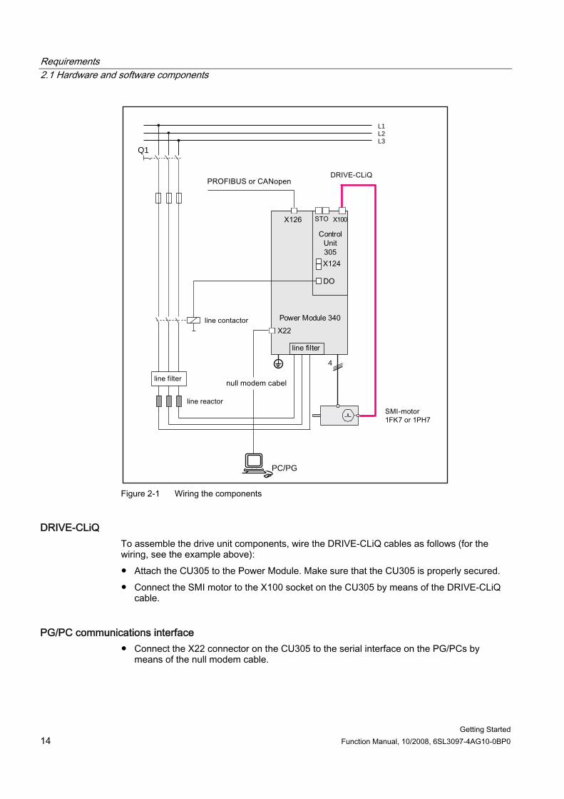
Wiring the drive unit Wire the components (see the following diagram) as described in the S110 Equipment Manual and S110 Function Manual.
Note The sections "Line-side power components" and "Cabinet design and EMC" in the S110 Equipment Manual describe the installation and wiring procedures.
Requirements 2.1 Hardware and software components
Getting Started 14 Function Manual, 10/2008, 6SL3097-4AG10-0BP0
L1L2L3
Q1
4
PC/PG
Figure 2-1 Wiring the components
DRIVE-CLiQ To assemble the drive unit components, wire the DRIVE-CLiQ cables as follows (for the wiring, see the example above): ● Attach the CU305 to the Power Module. Make sure that the CU305 is properly secured. ● Connect the SMI motor to the X100 socket on the CU305 by means of the DRIVE-CLiQ
cable.
PG/PC communications interface ● Connect the X22 connector on the CU305 to the serial interface on the PG/PCs by
means of the null modem cable.
Getting Started Function Manual, 10/2008, 6SL3097-4AG10-0BP0 15
Creating the drive project ONLINE 33.1 Creating the drive project ONLINE
The following steps are required to create a drive object ONLINE:
Table 3- 1 Creating a project ONLINE
Step Activity 1 Ensure that the commissioning requirements are fulfilled. 2 Create a project with the help of a Wizard. 3 Carry out an ONLINE search for DRIVE-CLiQ stations. 4 Transfer the configuration to the PG/PC. 5 Operate the motor using the "control panel" in STARTER (motor rotating).
3.2 Requirements The following prerequisites for creating a drive project ONLINE by means of the STARTER commissioning tool must be fulfilled: ● The components are assembled (see chapter 2). ● The drive unit has been switched on in accordance with regulations. ● Control Unit CU305 is connected to a PG/PC. ● The STARTER commissioning tool has been called up on the PG/PC.
Creating the drive project ONLINE 3.3 Creating projects ONLINE
Getting Started 16 Function Manual, 10/2008, 6SL3097-4AG10-0BP0
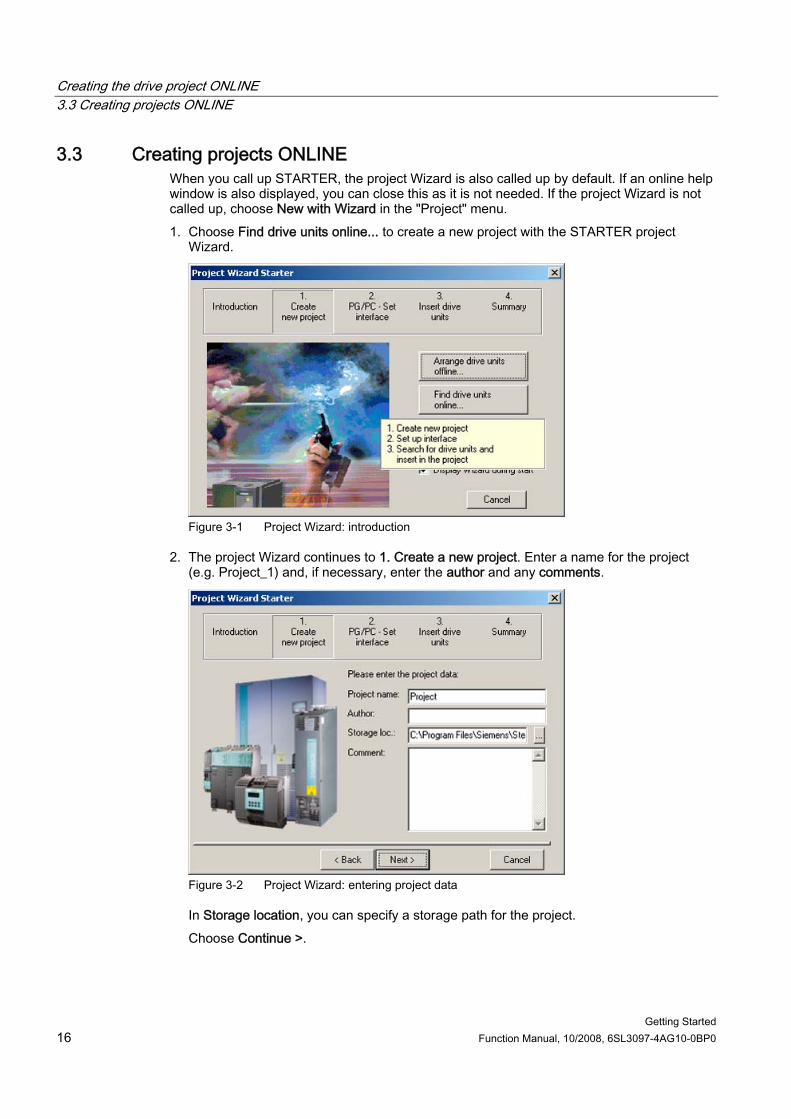
3.3 Creating projects ONLINE When you call up STARTER, the project Wizard is also called up by default. If an online help window is also displayed, you can close this as it is not needed. If the project Wizard is not called up, choose New with Wizard in the "Project" menu. 1. Choose Find drive units online... to create a new project with the STARTER project
Wizard.
Figure 3-1 Project Wizard: introduction
2. The project Wizard continues to 1. Create a new project. Enter a name for the project (e.g. Project_1) and, if necessary, enter the author and any comments.
Figure 3-2 Project Wizard: entering project data
In Storage location, you can specify a storage path for the project. Choose Continue >.
Creating the drive project ONLINE 3.3 Creating projects ONLINE
Getting Started Function Manual, 10/2008, 6SL3097-4AG10-0BP0 17
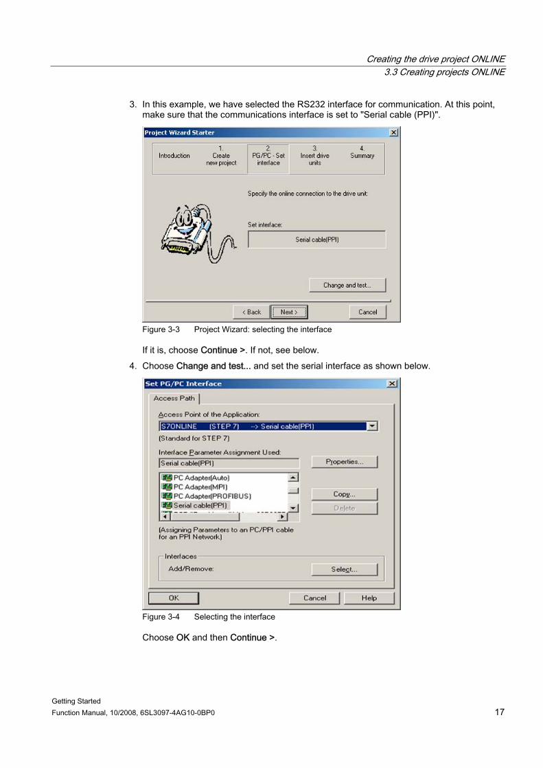
3. In this example, we have selected the RS232 interface for communication. At this point, make sure that the communications interface is set to "Serial cable (PPI)".
Figure 3-3 Project Wizard: selecting the interface
If it is, choose Continue >. If not, see below. 4. Choose Change and test... and set the serial interface as shown below.
Figure 3-4 Selecting the interface
Choose OK and then Continue >.
Creating the drive project ONLINE 3.3 Creating projects ONLINE
Getting Started 18 Function Manual, 10/2008, 6SL3097-4AG10-0BP0
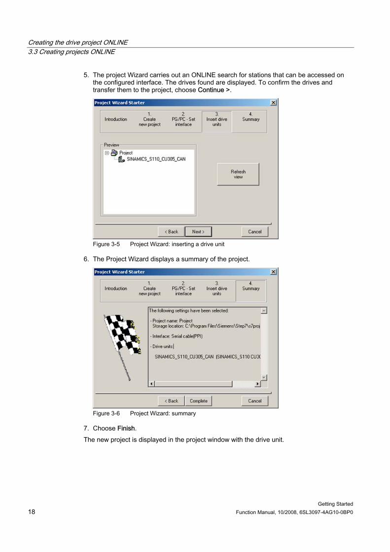
5. The project Wizard carries out an ONLINE search for stations that can be accessed on the configured interface. The drives found are displayed. To confirm the drives and transfer them to the project, choose Continue >.
Figure 3-5 Project Wizard: inserting a drive unit
6. The Project Wizard displays a summary of the project.
Figure 3-6 Project Wizard: summary
7. Choose Finish. The new project is displayed in the project window with the drive unit.
Creating the drive project ONLINE 3.3 Creating projects ONLINE
Getting Started Function Manual, 10/2008, 6SL3097-4AG10-0BP0 19
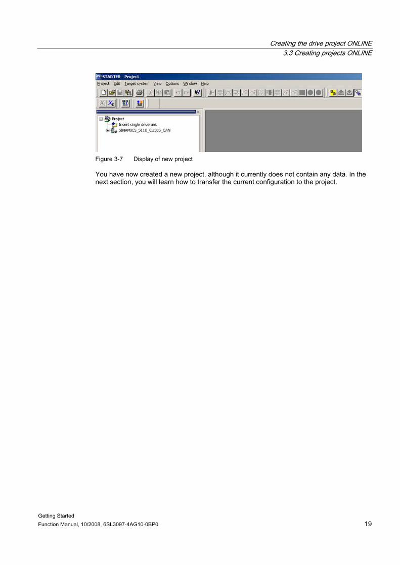
Figure 3-7 Display of new project
You have now created a new project, although it currently does not contain any data. In the next section, you will learn how to transfer the current configuration to the project.
Creating the drive project ONLINE 3.4 Transferring the configuration
Getting Started 20 Function Manual, 10/2008, 6SL3097-4AG10-0BP0
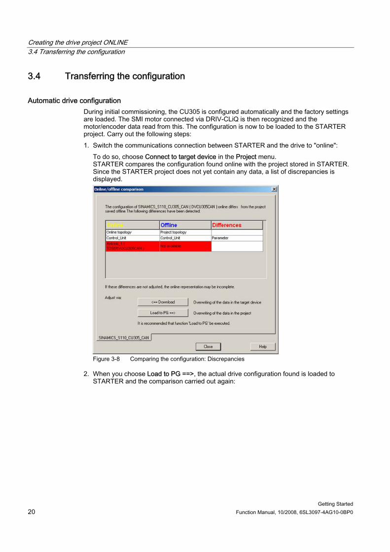
3.4 Transferring the configuration
Automatic drive configuration During initial commissioning, the CU305 is configured automatically and the factory settings are loaded. The SMI motor connected via DRIV-CLiQ is then recognized and the motor/encoder data read from this. The configuration is now to be loaded to the STARTER project. Carry out the following steps: 1. Switch the communications connection between STARTER and the drive to "online":
To do so, choose Connect to target device in the Project menu. STARTER compares the configuration found online with the project stored in STARTER. Since the STARTER project does not yet contain any data, a list of discrepancies is displayed.
Figure 3-8 Comparing the configuration: Discrepancies
2. When you choose Load to PG ==>, the actual drive configuration found is loaded to STARTER and the comparison carried out again:
Creating the drive project ONLINE 3.4 Transferring the configuration
Getting Started Function Manual, 10/2008, 6SL3097-4AG10-0BP0 21
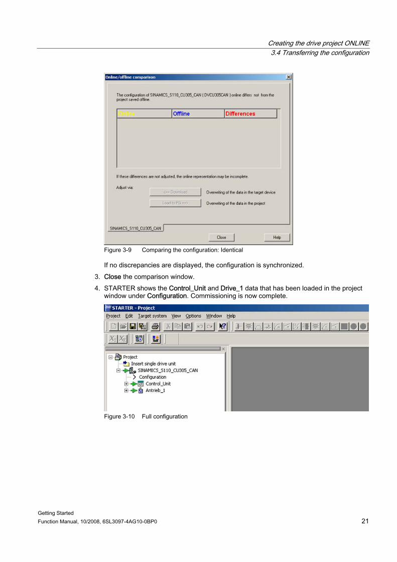
Figure 3-9 Comparing the configuration: Identical
If no discrepancies are displayed, the configuration is synchronized. 3. Close the comparison window. 4. STARTER shows the Control_Unit and Drive_1 data that has been loaded in the project
window under Configuration. Commissioning is now complete.
Figure 3-10 Full configuration
Creating the drive project ONLINE 3.4 Transferring the configuration
Getting Started 22 Function Manual, 10/2008, 6SL3097-4AG10-0BP0
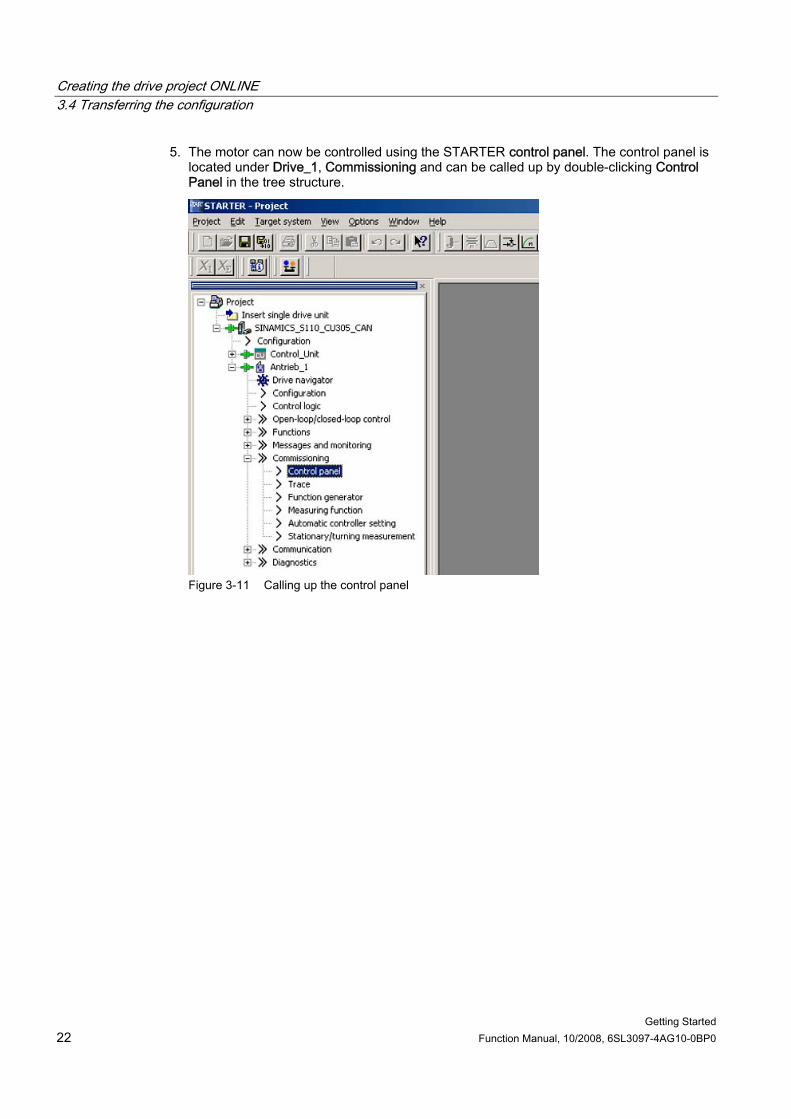
5. The motor can now be controlled using the STARTER control panel. The control panel is located under Drive_1, Commissioning and can be called up by double-clicking Control Panel in the tree structure.
Figure 3-11 Calling up the control panel
Creating the drive project ONLINE 3.5 Operating the drive with the control panel
Getting Started Function Manual, 10/2008, 6SL3097-4AG10-0BP0 23
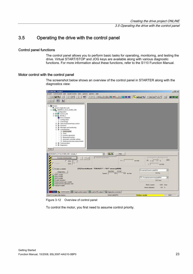
3.5 Operating the drive with the control panel
Control panel functions The control panel allows you to perform basic tasks for operating, monitoring, and testing the drive. Virtual START/STOP and JOG keys are available along with various diagnostic functions. For more information about these functions, refer to the S110 Function Manual.
Motor control with the control panel The screenshot below shows an overview of the control panel in STARTER along with the diagnostics view:
Figure 3-12 Overview of control panel
To control the motor, you first need to assume control priority.
Creating the drive project ONLINE 3.5 Operating the drive with the control panel
Getting Started 24 Function Manual, 10/2008, 6SL3097-4AG10-0BP0
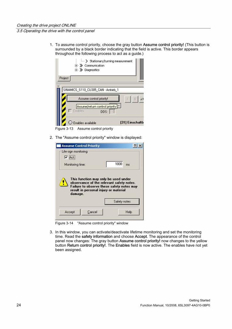
1. To assume control priority, choose the gray button Assume control priority! (This button is surrounded by a black border indicating that the field is active. This border appears throughout the following process to act as a guide.)
Figure 3-13 Assume control priority
2. The "Assume control priority" window is displayed:
Figure 3-14 "Assume control priority" window
3. In this window, you can activate/deactivate lifetime monitoring and set the monitoring time. Read the safety information and choose Accept. The appearance of the control panel now changes: The gray button Assume control priority! now changes to the yellow button Return control priority!. The Enables field is now active. The enables have not yet been assigned.
Creating the drive project ONLINE 3.5 Operating the drive with the control panel
Getting Started Function Manual, 10/2008, 6SL3097-4AG10-0BP0 25
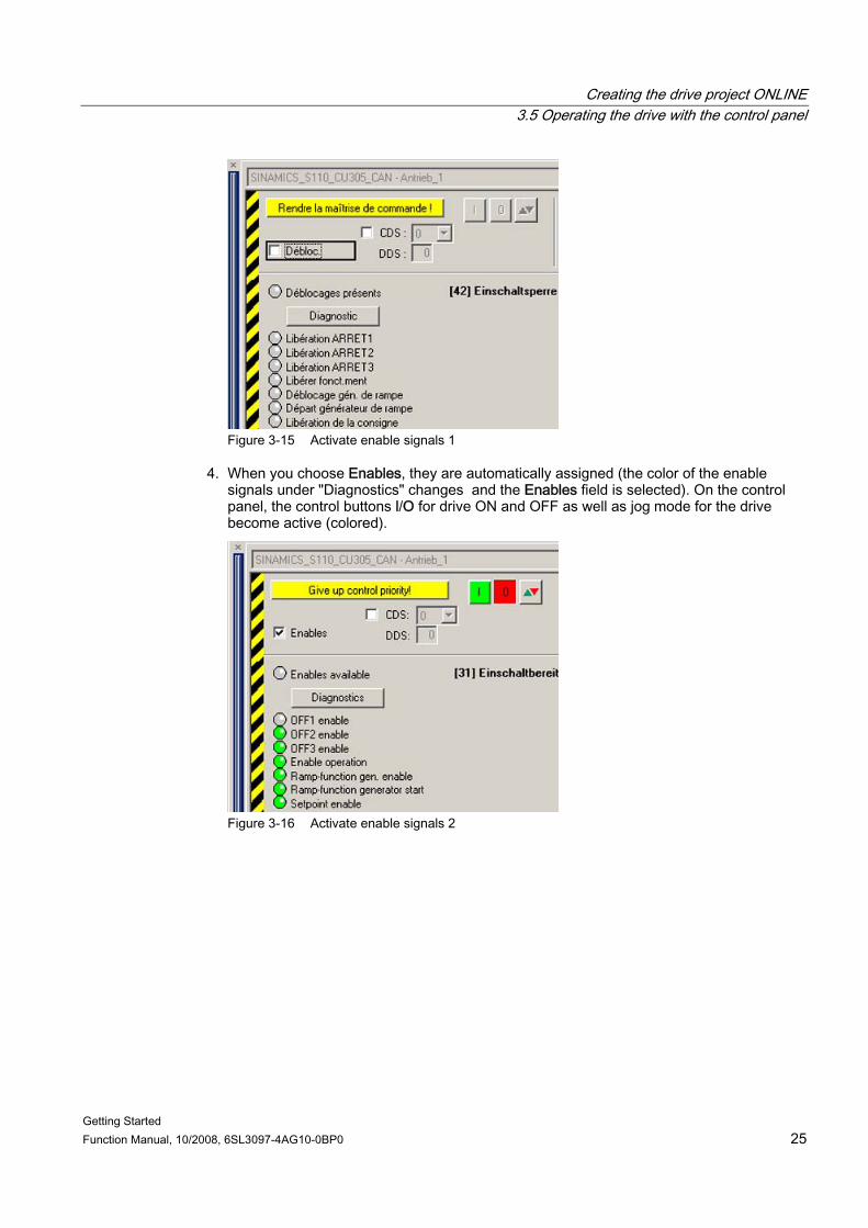
Figure 3-15 Activate enable signals 1
4. When you choose Enables, they are automatically assigned (the color of the enable signals under "Diagnostics" changes and the Enables field is selected). On the control panel, the control buttons l/O for drive ON and OFF as well as jog mode for the drive become active (colored).
Figure 3-16 Activate enable signals 2
Creating the drive project ONLINE 3.5 Operating the drive with the control panel
Getting Started 26 Function Manual, 10/2008, 6SL3097-4AG10-0BP0
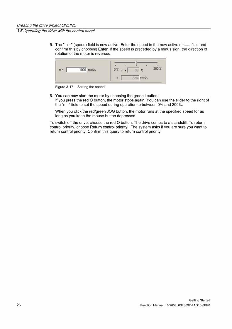
5. The " n =" (speed) field is now active. Enter the speed in the now active n=...... field and confirm this by choosing Enter. If the speed is preceded by a minus sign, the direction of rotation of the motor is reversed.
Figure 3-17 Setting the speed
6. You can now start the motor by choosing the green l button! If you press the red O button, the motor stops again. You can use the slider to the right of the "n =" field to set the speed during operation to between 0% and 200%. When you click the red/green JOG button, the motor runs at the specified speed for as long as you keep the mouse button depressed.
To switch off the drive, choose the red O button. The drive comes to a standstill. To return control priority, choose Return control priority!. The system asks if you are sure you want to return control priority. Confirm this query to return control priority.


www.siemens.com/motioncontrol
Änderungen vorbehalten© Siemens AG 2008
Siemens AGIndustry SectorDrive TechnologiesMotion Control SystemsPostfach 318091050 ERLANGENGERMANY