Embed Size (px)
Citation preview

Siemens D 21.3 · 2009
4/2 System overview
4/2 Overview
4/2 Benefits
4/2 Applications
4/3 Design
4/4 Function
4/8 Technical data
4/17 Selection and ordering data
4/18 Options
4/21 Description of the options
4/30 Line-side components
SINAMICS S150Converter Cabinet Units
© Siemens AG 2009

SINAMICS S150 Converter Cabinet Units
System overview
4/2 Siemens D 21.3 · 2009
4
! Overview
SINAMICS S150 Converter Cabinet Units
SINAMICS S150 converter cabinet units are particularly suitablefor all variable-speed single-axis drives with high performancerequirements, i.e., drives with:
• high dynamic requirements
• frequent braking cycles and high braking energy levels
• four-quadrant operation
SINAMICS S150 offers high-performance speed control withexcellent accuracy and a high dynamic response.
The following voltages and powers are available:
Degrees of protection are IP20 (standard), and IP21, IP23, IP43and IP54 (optional).
Line and motor-side components as well as additional monitor-ing devices can be installed in the converter cabinet units.
A wide range of electrical and mechanical components enablethe drive system to be optimized individually to suit customerrequirements.
! Benefits
The self-commutating, pulsed feed/feedback unit uses IGBTtechnology and is equipped with a Clean Power Filter. This com-bination guarantees extremely line-friendly behavior which ischaracterized by the following:
• negligible line harmonics as a result of the innovative CleanPower Filter (<< 1 %)
• the stringent limit values of IEEE519-1992 are fully compliedwith
• regenerative feedback (four-quadrant operation)
• tolerant to fluctuations in the line voltage
• operation on weak line supplies
• reactive power compensation is possible (inductive orcapacitive)
• high drive dynamic performance
Simple drive handling from engineering to operation thanks to
• compact, modular and service-friendly design
• problem-free configuration
• simple installation, as it is ready to connect
• fast, menu-driven commissioning without complexparameterization
• clear and convenient operation via a user-friendly graphicaloperator panel with measured values displayed in plain text orin a quasi-analog bar display.
! Applications
Typical applications for SINAMICS S150 include:
• test bay drives
• centrifuges
• elevators and cranes
• paper and rolling mill drives
• cross cutters and shears
• conveyor belts
• presses
• cable winches
Worldwide application
SINAMICS S150 converter cabinet units are manufactured incompliance with relevant international standards and regula-tions, and are therefore suitable for global use (see technicaldata).
Line voltage Type rating
380 ... 480 V 3 AC 110 ... 800 kW
500 ... 690 V 3 AC 75 ... 1200 kW
© Siemens AG 2009
SINAMICS S150 Converter Cabinet Units
System overview
4/3Siemens D 21.3 · 2009
4
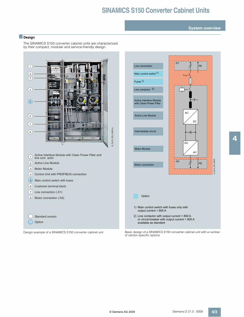
! Design
The SINAMICS S150 converter cabinet units are characterizedby their compact, modular and service-friendly design.
Design example of a SINAMICS S150 converter cabinet unit Basic design of a SINAMICS S150 converter cabinet unit with a numberof version-specific options
1
2
3
4
5
6
7
8
1
2
3
4
5
6
7
8
1Active Interface Module with Clean Power Filter andline cont actor
Active Line Module
Motor Module
Control Unit with PROFIBUS connection
Main control switch with fuses
Customer terminal block
Line connection (-X1)
Motor connection (-X2)
Standard version
Option
G_
D2
13
_E
N_
00
00
1a
-X2PE
-X1PELine connection
Main control switch1)
Fuses
Line contactor
1)
2)
Active Interface Modulewith Clean Power Filter
Active Line Module
Intermediate circuit
Motor Module
Motor connection
G_D213_EN_00002
DC
AC
DC
AC
Option
Main control switch with fuses only withoutput current < 800 A
1)
Line contactor with output current < 800 Aor circuit-breaker with output current > 800 Aavailable as standard
2)
© Siemens AG 2009

SINAMICS S150 Converter Cabinet Units
System overview
4/4 Siemens D 21.3 · 2009
4
! Function
AOP30 Advanced Operator Panel
An Advanced Operator Panel (AOP30) is fitted in the cabinetdoor of the converter for operation, monitoring and commission-ing tasks.
The user is guided by interactive menus through the drive-com-missioning screens. When commissioning the drive for the firsttime, only 6 motor parameters (which can be found on a motorrating plate) have to be entered on the AOP30. The control isthen optimized automatically to fine-tune the converter to themotor.
The AOP30's two-stage safety concept prevents unintentionalor unauthorized changes to settings. Operation of the drive fromthe operator panel can be disabled by the keyboard lock so thatonly parameter values and process variables can be displayedon the operating panel. The OFF key is factory-set to "active"but can also be "deactivated" by the customer. A password canbe used to prevent the unauthorized modification of converterparameters.
English, French, German, Italian, Spanish and Chinese arestored on the CU320 Control Unit's CompactFlash card as oper-ator panel languages. Russian, Polish and Czech are availablein addition to these standard panel languages. These can bedownloaded free of charge from the Internet under the followinglink:http://support.automation.siemens.com/
Examples of plain-text displays at various phases of operationare shown below.
The first commissioning process is performed using theoperator panel.
Only 6 motor parameters have to be entered:
Power, speed, current, cos phi, voltage and frequency of themotor.
This information can be found on the motor rating plate, andmust be entered into the screens on the display by following ashort, menu-assisted procedure. The motor cooling methodmust also be specified.
The next screen contains the parameter values that are used toautomatically optimize the control.
During operation, actual data are output on the display asabsolute values, such as setpoint and actual values, or it is pos-sible to parameterize up to three process variables as a quasi-analog bar display.
Any alarms which occur are signaled by flashing of the yellow"ALARM" LED, faults by lighting up of the red "FAULT" LED.There is also an indication of the cause displayed in plain text onthe display's status line (with counter/remedial measures).
Service / Commissioning
Drive commissioning
Device commissioning
AOP settings
AOP diagnosis
Help
G_
D0
11
_e
n_
00
04
7
Back Select
Motor dataBack
p0304 MOT.U_rated 400.0 Vp0305 MOT. I_rated 405.0 Ap0307 MOT.P_rated 235.0 kWp0308 MOT.CosPhi_ rated 0.870
Help Change OK
G_
D0
11
_e
n_
00
04
8G_D011_en_00049
Basic commissioningBackp0700 Pre-assignment BI S/G150 TM 32p1000 Default DI n_set TM 31 AIOp1080 Minimum speed 0.000 rpm -1
p1082 Maximum speed 1500.000 rpm -1
Help Change Further
Operation 12:25:30NsetFoutMPactNact:1450.0 rpm
1450.0048.50
2700410
rpmHzNmkW
1450.0 rpm385.3 V748
Nact
ImotVout
G_
D0
11
_E
N_
00
01
1b
0% 50 100%
0% 50 100%
G_D011_EN_00012b
Operation 12:25:30NSET 1465.50 rpm Pact 410 kWFout 48.50 Hz Vout 385.3 VImot748 ANact1465 rpm
(3 : Vector) Current fault in
F 07901 Motor overspeed
Help Alt Back Ack.
G_
D0
11
_e
n_
00
05
0G
_D
01
1_
en
_0
00
51
Motor overspeedFault val = 000000007 00000007 (hex)Cause:The maximum permisible positive ornegative speed has been exceeded.The maximum permissile positive speedis calculated as follows:Back
© Siemens AG 2009
SINAMICS S150 Converter Cabinet Units
System overview
4/5Siemens D 21.3 · 2009
4
! Function (continued)
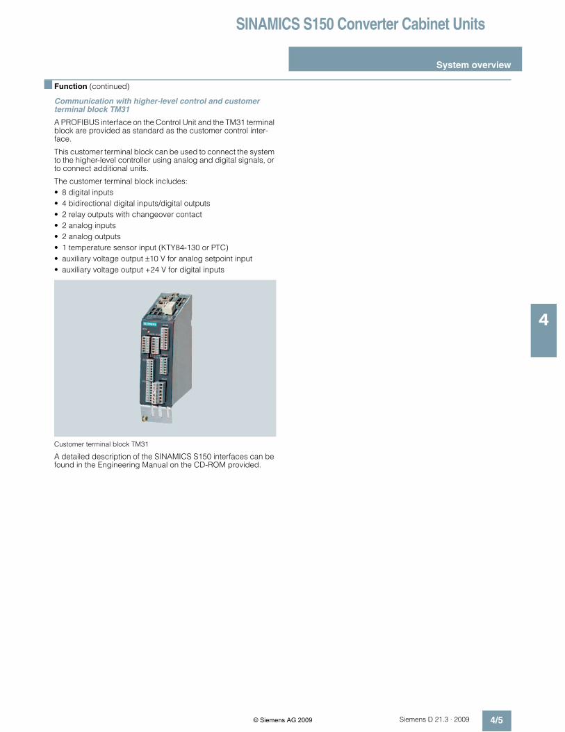
Communication with higher-level control and customerterminal block TM31
A PROFIBUS interface on the Control Unit and the TM31 terminalblock are provided as standard as the customer control inter-face.
This customer terminal block can be used to connect the systemto the higher-level controller using analog and digital signals, orto connect additional units.
The customer terminal block includes:
• 8 digital inputs
• 4 bidirectional digital inputs/digital outputs
• 2 relay outputs with changeover contact
• 2 analog inputs
• 2 analog outputs
• 1 temperature sensor input (KTY84-130 or PTC)
• auxiliary voltage output ±10 V for analog setpoint input
• auxiliary voltage output +24 V for digital inputs
Customer terminal block TM31
A detailed description of the SINAMICS S150 interfaces can befound in the Engineering Manual on the CD-ROM provided.
© Siemens AG 2009

SINAMICS S150 Converter Cabinet Units
System overview
4/6 Siemens D 21.3 · 2009
4
! Function (continued)
Open-loop and closed-loop control functions
The converter control includes a high-quality vector control withspeed and current control (with and without encoder).
Software and protective functions
The software functions available as standard are describedbelow:
Software and protective functions Description
Setpoint input The setpoint can be input both internally and externally. It is applied internally as a fixed setpoint, motor-ized potentiometer setpoint or jog setpoint and externally via the communications interface or an analoginput on the customer terminal block. The internal fixed setpoint and the motorized potentiometer setpointcan be switched over or adjusted using control commands from any interface.
Motor identification The automatic motor identification function makes commissioning faster and easier and optimizesclosed-loop control of the drive.
Ramp-function generator A user-friendly ramp-function generator, with separately adjustable ramp-up and ramp-down times,together with adjustable rounding times in the lower and upper speed ranges, improves the operatingbehavior and as a result of the smooth starting, significantly reduces the wear on mechanical compo-nents. The ramp-down ramps can be parameterized separately for emergency stop.
Kinetic buffering (KIP) For brief line supply failures, the kinetic energy of the rotating drive is used to buffer the DC link and there-fore prevents fault trips. The drive converter remains operational as long as the drive can provide regen-erative energy as a result of its motion and the DC link voltage does not drop below the trip threshold.When the line supply recovers within this time, the drive is again accelerated up to its setpoint speed.
Automatic restart 1) The automatic restart switches the drive on again when the power is restored after a power failure, andramps up to the current speed setpoint.
Flying restart 1) The "Flying restart" function allows the converter to switch on to a motor that is still turning.
Technology controller The "Technology controller" function module allows simple control functions to be implemented,e.g. level control or volumetric flow control. The technology controller is a PID controller, whereby the dif-ferentiator can be switched to the control deviation channel or the actual value channel (factory setting).The P, I, and D components can be set separately.
Free function blocks Using the freely programmable function blocks, it is easy to implement logic and arithmetic functions forcontrolling the SINAMICS S150 unit. The blocks can be programmed by means of an operator panel orthe STARTER commissioning tool.
Drive Control Chart (DCC) Drive Control Chart (DCC) is an additional tool for the easy configuration of process-oriented functions forthe SINAMICS S150. The block library contains a large selection of control, arithmetic and logic blocks aswell as extensive open-loop and closed-loop control functions. The user-friendly DCC editor enables easygraphical configuration and a clear representation of control loop structures as well as a high degree ofreusability of existing diagrams. DCC is an add-on to the STARTER commissioning tool (→Tools andconfiguring).
I2 t sensing for motor protection The motor temperature is calculated in a motor model stored in the drive converter software. More exactsensing of the temperature, which also takes into account the influence of the ambient temperature, ispossible by means of direct temperature sensing using KTY84 sensors in the motor winding.
Motor temperature evaluation Motor protection by evaluating a KTY84 or PTC temperature sensor. When a temperature sensor isconnected, the limit values can be set for alarm or trip. When a PTC thermistor is connected, the systemreaction to triggering of the thermistor (alarm or trip) can be defined.
Motor blocking protection A blocked motor is detected and protected against thermal overloading by a fault trip.
Safety Integrated
Safe Torque Off (STO) Function description
This function is a mechanism that prevents the drive from restarting unexpectedly, in accordance withEN 60204-1, Section 5.4. Safe Torque Off disables the drive pulses and disconnects the power supply tothe motor (corresponds to Stop Category 0 of EN 60204-1). The drive is reliably torque-free. This state ismonitored internally in the drive.
Application, customer benefits
STO has the immediate effect that the drive cannot supply any torque-generating energy. STO can beused wherever the drive will naturally reach a standstill due to load torque or friction in a sufficiently shorttime or when "coasting down" of the drive will not have any relevance for safety.
1) Factory setting: not activated (can be parameterized).
G_D211_XX_00210
t
v STO
© Siemens AG 2009

SINAMICS S150 Converter Cabinet Units
System overview
4/7Siemens D 21.3 · 2009
4
! Function (continued)
Software and protective functions Description
Safety Integrated
Safe Stop 1 (SS1) Function description
The Safe Stop 1 function can safely stop the drive in accordance with EN 60204-1, Stop Category 1.When the SS1 function is selected, the drive independently brakes along a quick stop ramp (OFF3) andautomatically activates Safe Torque Off when the parameterized safety delay timer has expired.
Application, customer benefits
This integrated self-braking function eliminates the need for complex external monitoring equipment. Fur-thermore, it is often possible to eliminate mechanical brakes which wear, or to lessen the load on them, sothat maintenance costs and the stresses on the machine can be reduced.
Safe Stop 1 is employed for applications which require monitored braking, e.g. on centrifuges orconveyor vehicles.
The safety functions integrated in SINAMICS S150 fulfill the specifications of
• DIN EN ISO 13849-1 Category 3 (previously EN954-1)
• Safety Integrity Level (SIL) 2 according to EN 61508
• Performance Level (PL) d according to EN ISO 13849-1In addition, the Safety Integrated functions of the SINAMICS S150 are generally certified by independentinstitutes. An up-to-date list of certified components is available on request from your local Siemensoffice.
Terminal module for controlling STOand SS1 functions (order code K82)
The terminal module is used to control the "Basic Safety Functions" over a wide voltage range from 24 Vup to 240 V DC/AC. This means that the "STO" and "SS1" safety functions can be flexibly controlled fromthe signal voltages of the plant.
See → Description of the options (K82)
Power unit protection
Ground fault monitoring at output end A ground fault at the output end is detected by an aggregate current monitor and results in shutdown ingrounded-neutral systems.
Electronic short-circuit protection atthe output
A short-circuit (e.g. on the converter output terminals, in the motor cable or in the motor terminal box) isdetected at the output end and the converter shuts down with a fault message.
Thermal overload protection An alarm is issued first when the overtemperature threshold responds. If the temperature rises further, theunit either shuts down or independently adjusts the pulse frequency or output current so that a reductionin the thermal load is achieved. After the cause of the fault has been eliminated (e.g. improving the cool-ing), the drive system automatically returns to the original operating values.
STO
G_D211_XX_00205
t
v
∆t
© Siemens AG 2009

SINAMICS S150 Converter Cabinet Units
System overview
4/8 Siemens D 21.3 · 2009
4
! Technical data
General technical data
Deviations from the specified classes are underlined.
Electrical data
Line voltages • 380 ... 480 V 3 AC, ±10 % (-15 % < 1 min)
• 500 ... 690 V 3 AC, ±10 % (-15 % < 1 min)
Types of supplies TN/TT supplies or insulated supplies (IT supplies)
Line frequency 47 Hz ... 63 Hz
Output frequency 0 Hz ... 300 Hz
Line power factor Adjustable (factory-set to cos ϕ = 1)
Control method Vector control with and without encoder, servo control or V/f control
Fixed speeds 15 fixed speeds plus 1 minimum speed, programmable (in the default setting, 3 fixed setpoints plus1 minimum speed are selectable using terminal block / PROFIBUS)
Skipped speed ranges 4, parameterizable
Setpoint resolution 0.001 rpm digital (14 bits + sign)
12 bit analog
Braking operation Four-quadrant operation is possible as standard(optional via a braking unit if braking is required when power fails)
Mechanical data
Degree of protection IP20 (higher degrees of protection up to IP54 optional)
Protection class acc. to EN 61800-5-1
Type of cooling Forced air cooling
Shock protection BGV A3
Cabinet system Rittal TS 8, doors with double-barb lock, three-section base plates for cable entry
Paint finish RAL 7035 (indoor requirements)
Compliance with standards
Standards EN 60146-1, EN 61800-2, EN 61800-3, EN 61800-5-1, EN 60204-1, EN 60529, IEEE519-1992
CE marking acc. to EMC directive No. 2004/108/EC and low-voltage directive No. 2006/95/EC
RI suppression The SINAMICS S150 drive converter systems are not designed for connection to the public powernetwork ("first environment"). RI suppression is compliant with the EMC product standard for variable-speed drives EN 61800-3, "Second environment" (industrial networks). The equipment can causeelectromagnetic interference when it is connected to the public network.
Ambient conditions During operation During storage During transport
Ambient temperature 0 °C ... +40 °C
up to +50 °C see derating data
-25 °C ... +55 °C -25 °C ... +70 °C
from -40 °C for 24 hours
Relative air humidity(condensation not permissible)
5% ... 95 %corr. to 3K3 acc. to IEC 60721-3-3
5 % ... 95 %corr. to 1K4 acc. to IEC 60721-3-1
5 % ... 95 % at 40 °Ccorr. to 2K3 acc. to IEC 60721-3-2
Installation altitude Up to 2000 m above sea level without derating, > 2000 m, see derating data
Mechanical stability During operation During storage During transport
Vibratory load
• Deflection 0.075 mm at 10 Hz ... 58 Hz 1.5 mm at 5 Hz ... 9 Hz 3.5 mm at 5 Hz ... 9 Hz
• Acceleration 9.8 m/s2 at > 58 Hz ... 200 Hz-
5 m/s² at > 9 Hz ... 200 Hz corr.to 1M2 acc. to IEC 60721-3-1
10 m/s² at > 9 Hz ... 200 Hz corr.to 2M2 acc. to IEC 60721-3-2
Shock load
• Acceleration 100 m/s2 at 11 ms corr. to 3M4acc. to IEC 60721-3-3
40 m/s² at 22 ms corr. to 1M2acc. to IEC 60721-3-1
100 m/s² at 11 ms corr. to 2M2acc. to IEC 60721-3-2
© Siemens AG 2009

SINAMICS S150 Converter Cabinet Units
System overview
4/9Siemens D 21.3 · 2009
4
! Technical data (continued)
Derating data
Current derating as a function of installation altitude/ambient temperature
If the drive converters are operated at an installation altitude> 2000 m above sea level, the permissible drive converter out-put currents must be reduced in accordance with the followingtables.
The degree of protection of the converter cabinets must also betaken into account. The listed derating data already includecompensation between the installation altitude and ambienttemperature (incoming air temperature at the inlet to theconverter cabinet).
Current derating as a function of ambient temperature (incoming air temperature) and installation altitude for cabinet units with degrees of protectionIP20, IP21, IP23 and IP43
Current derating as a function of ambient temperature (incoming air temperature) and installation altitude for cabinet units with degree of protectionIP54
Voltage derating as a function of installation altitude
In addition to current derating, voltage derating must be takeninto consideration according to the following tables for installa-tion altitudes > 2000 m above sea level:
Voltage derating as a function of installation altitude
Install. altitudeabove sea level
Current derating at an ambient temperature of
m 20 °C 25 °C 30 °C 35 °C 40 °C 45 °C 50 °C
0-2000 95.0 % 87.0 %
2001-2500 100 % 96.3 % 91.4 % 83.7 %
2501-3000 96.2 % 92.5 % 87.9 % 80.5 %
3001-3500 96.7 % 92.3 % 88.8 % 84.3 % 77.3 %
3501-4000 97.8 % 92.7 % 88.4 % 85.0 % 80.8 % 74.0 %
Install. altitudeabove sea level
Current derating at an ambient temperature of
m 20 °C 25 °C 30 °C 35 °C 40 °C 45 °C 50 °C
0-2000 95.0% 87.5 % 80.0 %
2001-2500 100 % 96.3 % 91.4 % 84.2 % 77.0 %
2501-3000 96.2 % 92.5 % 87.9 % 81.0 % 74.1 %
3001-3500 97.7 % 92.3 % 88.8 % 84.3 % 77.7 % 71.1 %
3501-4000 97.8% 92.7 % 88.4 % 85.0 % 80.8 % 74.7 % 68.0 %
Install. altitudeabove sea level
Voltage derating for a rated input voltage of
m 380 V 400 V 420 V 440 V 460 V 480 V 500 V 525 V 575 V 600 V 660 V 690 V
0-2000 100 %
2001-2250 96 % 96 %
2251-2500 100 % 98 % 94 % 100 % 98 % 94 %
2501-2750 98 % 94 % 90 % 94 % 90 %
2751-3000 95 % 91 % 88 % 91 % 88 %
3001-3250 97 % 93 % 89 % 85 % 98 % 89 % 85 %
3251-3500 98 % 93 % 89 % 85 % 82 % 98 % 94 % 85 % 82 %
3501-3750 95 % 91 % 87 % 83 % 79 % 95 % 91 % 83 % 79 %
3751-4000 96 % 92 % 87 % 83 % 80 % 76 % 91 % 87 % 80 % 76 %
© Siemens AG 2009

SINAMICS S150 Converter Cabinet Units
System overview
4/10 Siemens D 21.3 · 2009
4
! Technical data (continued)
Overload capability
The SINAMICS S150 converter cabinet units are equipped withan overload reserve to deal with breakaway torques, for exam-ple. If larger surge loads occur, this must be taken into accountwhen configuring. In drives with overload requirements, theappropriate base load current must, therefore, be used as abasis for the required load.
The criterion for overload is that the drive is operated with itsbase load current before and after the overload occurs on thebasis of a duty cycle duration of 300 s.
The base load current IL for a low overload is based on a dutycycle of 110 % for 60 s or 150 % for 10 s.
Low overload
The base load current IH for a high overload is based on a dutycycle of 150 % for 60 s or 160 % for 10 s.
High overload
Degrees of protection of cabinet units
The EN 60529 standard covers the protection of electrical equip-ment by means of housings, covers or equivalent, and includes:
• Protection of persons against accidental contact with live ormoving parts within the housing and protection of the equip-ment against the ingress of solid foreign matter (touch protec-tion and protection against ingress of solid foreign bodies)
• Protection of the equipment against the ingress of water(water protection)
• Abbreviations for the internationally agreed degrees ofprotection.
The degrees of protection are specified by abbreviationscomprising the code letters IP and two digits.
60 s
10 s
300 s
t
1.1 x IL
1.5 x IL
Short-time current 110 %
Short-time current 150 %
Rated current (continuous)
Converter current
G_D213_EN_00035
Base load current ILfor low overload
IL
Irated
60 s
10 s
t
1.5 x IH
1.6 x IH Short-time current 160 %
Short-time current 150 %
Rated current (continuous)
Converter current
G_D213_EN_00036
Base load current IH for high overload
IH
Irated
300 s
Degrees ofprotection of theconverter cabinetunit
First digit(touch protection andprotection againstingress of foreignsolid matter)
Second digit(protection of theequipment against theingress of water)
IP20 (standard) Protected against solidforeign bodies, diame-ter ≥ 12.5 mm.
No water protection
IP21 (option M21) Protected against solidforeign bodies, diame-ter ≥ 12.5 mm.
Protected against dripwater
Vertically falling dripwater shall not have aharmful effect.
IP23 (option M23) Protected against solidforeign bodies, diame-ter ≥ 12.5 mm.
Protected against spraywater
Water sprayed on bothsides of the vertical atan angle of up to 60°shall not have a harmfuleffect.
IP43 (option M43) Protected against solidforeign bodies, diame-ter ≥ 1 mm.
Protected against spraywater
Water sprayed on bothsides of the vertical atan angle of up to 60°shall not have a harmfuleffect.
IP54 (option M54) Dust protected.
Ingress of dust is nottotally prevented, butdust must not beallowed to enter in suchquantities that the func-tioning or safety of theequipment is impaired.
Protected againstsplash water
Water splashing ontothe enclosure from anydirection shall not havea harmful effect.
© Siemens AG 2009

SINAMICS S150 Converter Cabinet Units
System overview
4/11Siemens D 21.3 · 2009
4
! Technical data (continued)
EMC information
The term "electromagnetic compatibility" describes - accordingto the definition of the EMC Directive - the "capability of a deviceto work satisfactorily in the electromagnetic environment withoutitself causing electromagnetic interference which is unaccept-able for other devices present in this environment". To guaranteethat the appropriate EMC directives are observed, the devicesmust demonstrate a sufficiently high noise immunity, and alsothe emitted interference must be limited to acceptable values.
The EMC requirements for "Variable-speed drive systems" aredescribed in the product standard EN 61800-3. A variable-speed drive system (or Power Drive System PDS) consists of thedrive converter and the electric motor including cables. Thedriven machine is not part of the drive system.
EN 61800-3 defines different limits depending on the location ofthe drive system, referred to as the first and second environ-ments.
Residential buildings or locations at which the drive system isdirectly connected to a public low-voltage supply without inter-mediate transformer are defined as the first environment.
A second environment involves locations outside residentialareas or industrial sites which are supplied from the medium-voltage network via a separate transformer.
Four different categories are defined in EN 61800-3 Ed.2 de-pending on the location and the power of the drive:
• Category C1: Drive systems for rated voltages less than1000 V for unrestricted use in the first environment.
• Category C2: Stationary drive systems for rated voltages lessthan 1000 V for use in the second environment. Use in the firstenvironment is possible if the drive system is distributed andinstalled by qualified personnel. The warning and installationinformation supplied by the manufacturer must be observed.
• Category C3: Drive systems for rated voltages less than1000 V for exclusive use in the second environment.
• Category C4: Drive systems for rated voltages greater than orequal to 1000 V or for rated currents greater than or equal to400 A for use in complex systems in the second environment.
The following diagram shows how the four categories are as-signed to the first and second environments:
SINAMICS S150 is almost exclusively used in the second envi-ronment (Categories C3 and C4).
To limit the emitted interference, SINAMICS S150 is equippedwith a line filter as standard, according to the limits defined inCategory C3. Optional line filters are available on request for usein the first environment (Category C2).
SINAMICS S150 fulfills the noise-immunity requirements de-fined in EN 61800-3 for the second environment and, conse-quently, also the lower noise immunity values in the first environ-ment.
The warning and installation information (part of the equipmentdocumentation) must be observed.
Grounding
The protective conductor cross-section must be dimensionedtaking into account the following data:
• In the case of a ground fault caused by voltage losses of theground fault current on the protective conductor, no impermis-sibly high contact voltages may occur (< 50 V AC or < 120 VDC, EN 50178 Section 5.3.2.2, IEC 60364, IEC 60543).
• The protective conductor must not be excessively loaded byany ground fault current it carries.
• If it is possible for continuous currents to flow through the pro-tective conductor when a fault occurs in accordance withEN 50 178 Section 8.3.3.4, the protective conductor cross-section must be dimensioned for this continuous current.
The protective conductor cross-section must be selected ac-cording to EN 60204-1, EN 60439-1, IEC 60364.
• Switchgear and motors are usually grounded separatelyvia a local ground electrode. With this constellation, theground fault current flows via the parallel ground connectionsand is divided. In spite of the protective conductor cross-sec-tions used in accordance with the table above, no inadmissi-ble touch voltages occur with this grounding system.However, from experience gained with different groundingconstellations, we recommend that the ground cable from themotor returns directly to the drive converter. For EMC reasonsand to prevent bearing currents, symmetrical motor cablesrather than four-wire cables should be used here. The groundconnection (protective conductor, PE) must be routed sepa-rately or arranged symmetrically in the motor cable. The sym-metry of the PE conductor is achieved using a conductor sur-rounding all phase conductors or using a cable with asymmetrical arrangement of the three phase conductors andthree ground conductors.
• Through their high-speed control, the converters limit the loadcurrent (motor and ground fault currents) to an rms value cor-responding to the rated current.Considering this situation, we recommend the protectiveconductor cross-section to be analog with the cross-section ofthe external conductor for grounding the control cabinet.
C1
C2
C3
C4
First
environment
Second
environment
G D213 EN 00009
Cross-sectionexternal conductor
Minimum cross-section ofexternal protective conductor
up to 16 mm2 Minimum cross-section of externalconductor
16 mm2 to 35 mm2 16 mm2
from 35 mm2 At least half the cross-section of externalconductor
© Siemens AG 2009

SINAMICS S150 Converter Cabinet Units
System overview
4/12 Siemens D 21.3 · 2009
4
! Technical data (continued)
Line voltage380 … 480 V 3 AC
6SL3710-7LE32-1AA0
6SL3710-7LE32-6AA0
6SL3710-7LE33-1AA0
6SL3710-7LE33-8AA0
6SL3710-7LE35-0AA0
6SL3710-7LE36-1AA0
Type rating
• at IL (50 Hz 400 V) 1) kW 110 132 160 200 250 315
• at IH (50 Hz 400 V) 1) kW 90 110 132 160 200 250
• at IL (60 Hz 460 V) 2) hp 150 200 250 300 400 500
• at IH (60 Hz 460 V) 2) hp 150 200 200 250 350 350
Output current
• Rated current IN A A 210 260 310 380 490 605
• Base load current IL3) A 205 250 302 370 477 590
• Base load current IH4) A 178 233 277 340 438 460
• Maximum current Imax A A 307 375 453 555 715 885
Feed/feedback current
• Rated current IN E A 197 242 286 349 447 549
• Maximum current Imax E A 315 390 570 570 735 907
Current requirement, max. 5)
• 24 V DC auxiliary power supply A Internal Internal Internal Internal Internal Internal
Pulse frequency 6)
• Rated frequency kHz 2 2 2 2 2 1.25
• Pulse frequency, max.
- without current derating kHz 2 2 2 2 2 1.25
- with current derating kHz 8 8 8 8 8 7.5
Power loss, max. 7)
• at 50 Hz 400 V kW 6.31 7.55 10.01 10.72 13.13 17.69
• at 60 Hz 460 V kW 6.49 7.85 10.45 11.15 13.65 18.55
Cooling-air requirement m3/s 0.58 0.7 1.19 1.19 1.19 1.96
Sound pressure level LpA(1 m) at 50/60 Hz
dB(A) 71/73 71/73 72/74 72/74 72/74 77/79
Line connection U1, V1, W1 M12 screw M12 screw M12 screw M12 screw M12 screw M12 screw
• Conductor cross-section, max.(DIN VDE)
mm2 4 x 240 4 x 240 4 x 240 4 x 240 4 x 240 4 x 240
Motor connectionU2/T1, V2/T2, W2/T2
M12 screw M12 screw M12 screw M12 screw M12 screw M12 screw
• Conductor cross-section, max.(DIN VDE)
mm2 2 x 150 2 x 150 2 x 150 2 x 150 2 x 240 4 x 240
Cable length, max.
• Shielded m 300 300 300 300 300 300
• Unshielded m 450 450 450 450 450 450
PE/GND connection M12 screw M12 screw M12 screw M12 screw M12 screw M12 screw
• Conductor cross-section, max.(DIN VDE)
mm2 240 240 240 240 240 240
Degree of protection IP20 IP20 IP20 IP20 IP20 IP20
Dimensions
• Width mm 1400 1400 1600 1800 1800 2200
• Height mm 2000 2000 2000 2000 2000 2000
• Depth mm 600 600 600 600 600 600
Weight, approx. kg 708 708 892 980 980 1716
Frame size F F G G G H
1) Rated power of a typ. 6-pole standard asynchronous (induction) motorbased on IL or IH at 400 V 3 AC 50 Hz.
2) Rated power of a typ. 6-pole standard asynchronous (induction) motorbased on IL or IH at 460 V 3 AC 60 Hz.
3) The base load current IL is based on a duty cycle of 110 % for 60 s or150 % for 10 s with a duty cycle duration of 300 s.
4) The base load current IH is based on a duty cycle of 150 % for 60 s or160 % for 10 s with a duty cycle duration of 300 s.
5) If the drive closed-loop control is still to remain active after a main infeedfailure, then the equipment must be provided with an external 24 V DCsupply.
6) For the correlation between the pulse frequency and maximum outputcurrent/output frequency, see the Engineering Manual on the CD-ROMprovided.
7) The specified power loss represents the maximum value at 100% utiliza-tion. The value is lower under normal operating conditions.
© Siemens AG 2009
SINAMICS S150 Converter Cabinet Units
System overview
4/13Siemens D 21.3 · 2009
4
! Technical data (continued)
Line voltage380 … 480 V 3 AC
6SL3710-7LE37-5AA0
6SL3710-7LE38-4AA0
6SL3710-7LE41-0AA0
6SL3710-7LE41-2AA0
6SL3710-7LE41-4AA0
Type rating
• at IL (50 Hz 400 V) 1) kW 400 450 560 710 800
• at IH (50 Hz 400 V) 1) kW 315 400 450 560 710
• at IL (60 Hz 460 V 2) hp 600 700 800 1000 1000
• at IH (60 Hz 460 V) 2) hp 450 600 700 900 1000
Output current
• Rated current IN A A 745 840 985 1260 1405
• Base load current IL3) A 725 820 960 1230 1370
• Base load current IH4) A 570 700 860 1127 1257
• Maximum current Imax A A 1087 1230 1440 1845 2055
Feed/feedback current
• Rated current IN E A 674 759 888 1133 1262
• Maximum current Imax E A 1118 1260 1477 1891 2107
Current requirement, max. 5)
• 24 V DC aux. power supply A Internal Internal Internal Internal Internal
Pulse frequency 6)
• Rated frequency kHz 1.25 1.25 1.25 1.25 1.25
• Pulse frequency, max.
- without current derating kHz 1.25 1.25 1.25 1.25 1.25
- with current derating kHz 7.5 7.5 7.5 7.5 7.5
Power loss, max. 7)
• at 50 Hz 400 V kW 20.63 21.1 27.25 33.05 33.95
• at 60 Hz 460 V kW 21.75 22.25 28.65 34.85 35.85
Cooling-air requirement m3/s 1.96 1.96 2.6 2.6 2.6
Sound pressure level LpA(1 m) at 50/60 Hz
dB(A) 77/79 77/79 77/79 78/80 78/80
Line connectionU1, V1, W1
M12 screw M12 screw M12 screw M12 screw M12 screw
• Conductor cross-section, max.(DIN VDE)
mm2 4 x 240 8 x 240 8 x 240 8 x 240 8 x 240
Motor connectionU2/T1, V2/T2, W2/T2
M12 screw M12 screw M12 screw M12 screw M12 screw
• Conductor cross-section, max.(DIN VDE)
mm2 4 x 240 4 x 240 6 x 240 6 x 240 6 x 240
Cable length, max.
• Shielded m 300 300 300 300 300
• Unshielded m 450 450 450 450 450
PE/GND connection M12 screw M12 screw M12 screw M12 screw M12 screw
• Conductor cross-section, max.(DIN VDE)
mm2 240 240 240 240 240
Degree of protection IP20 IP20 IP20 IP20 IP20
Dimensions
• Width mm 2200 2200 2800 2800 2800
• Height mm 2000 2000 2000 2000 2000
• Depth mm 600 600 600 600 600
Weight, approx. kg 1731 1778 2408 2408 2408
Frame size H H J J J
1) Rated power of a typ. 6-pole standard asynchronous (induction) motorbased on IL or IH at 400 V 3 AC 50 Hz.
2) Rated power of a typ. 6-pole standard asynchronous (induction) motorbased on IL or IH at 460 V 3 AC 60 Hz.
3) The base load current IL is based on a duty cycle of 110 % for 60 s or150 % for 10 s with a duty cycle duration of 300 s.
4) The base load current IH is based on a duty cycle of 150 % for 60 s or160 % for 10 s with a duty cycle duration of 300 s.
5) If the drive closed-loop control is still to remain active after a main infeedfailure, then the equipment must be provided with an external 24 V DCsupply.
6) For the correlation between the pulse frequency and maximum outputcurrent/output frequency, see the Engineering Manual on the CD-ROMprovided.
7) The specified power loss represents the maximum value at 100% utiliza-tion. The value is lower under normal operating conditions.
© Siemens AG 2009

SINAMICS S150 Converter Cabinet Units
System overview
4/14 Siemens D 21.3 · 2009
4
! Technical data (continued)
1) Rated power of a typ. 6-pole standard asynchronous (induction) motorbased on IL or IH at 500 V or 690 V 3 AC 50 Hz.
2) Rated power of a typ. 6-pole standard asynchronous (induction) motorbased on IL or IH at 575 V 3 AC 60 Hz.
3) The base load current IL is based on a duty cycle of 110 % for 60 s or150 % for 10 s with a duty cycle duration of 300 s.
4) The base load current IH is based on a duty cycle of 150 % for 60 s or160 % for 10 s with a duty cycle duration of 300 s.
5) If the drive closed-loop control is still to remain active after a main infeedfailure, then the equipment must be provided with an external 24 V DCsupply.
6) For the correlation between the pulse frequency and maximum outputcurrent/output frequency, see the Engineering Manual on the CD-ROMprovided.
7) The specified power loss represents the maximum value at 100% utiliza-tion. The value is lower under normal operating conditions.
Line voltage500 … 690 V 3 AC
6SL3710-7LG28-5AA0
6SL3710-7LG31-0AA0
6SL3710-7LG31-2AA0
6SL3710-7LG31-5AA0
6SL3710-7LG31-8AA0
6SL3710-7LG32-2AA0
Type rating
• at IL (50 Hz 690 V) 1) kW 75 90 110 132 160 200
• at IH (50 Hz 690 V) 1) kW 55 75 90 110 132 160
• at IL (50 Hz 500 V) 1) kW 55 55 75 90 110 132
• at IH (50 Hz 500 V) 1) kW 45 55 75 90 90 110
• at IL (60 Hz 575 V) 2) hp 75 75 100 150 150 200
• at IH (60 Hz 575 V) 2) hp 75 75 100 125 150 200
Output current
• Rated current IN A A 85 100 120 150 175 215
• Base load current IL3) A 80 95 115 142 170 208
• Base load current IH4) A 76 89 117 134 157 192
• Maximum current Imax A A 120 142 172 213 255 312
Feed/feedback current
• Rated current IN E A 86 99 117 144 166 202
• Maximum current Imax E A 125 144 170 210 253 308
Current requirement, max. 5)
• 24 V DC auxiliary powersupply
A Internal Internal Internal Internal Internal Internal
Pulse frequency 6)
• Rated frequency kHz 1.25 1.25 1.25 1.25 1.25 1.25
• Pulse frequency, max.
- without current derating kHz 1.25 1.25 1.25 1.25 1.25 1.25
- with current derating kHz 7.5 7.5 7.5 7.5 7.5 7.5
Power loss, max. 7)
• at 50 Hz 690 V kW 5.12 5.38 5.84 5.75 11.02 11.44
• at 60 Hz 575 V kW 4.45 4.65 5.12 4.97 11.15 11.56
Cooling-air requirement m3/s 0.58 0.58 0.58 0.58 1.19 1.19
Sound pressure level LpA(1 m) at 50/60 Hz
dB(A) 71/73 71/73 71/73 71/73 75/77 75/77
Line connectionU1, V1, W1
M12 screw M12 screw M12 screw M12 screw M12 screw M12 screw
• Conductor cross-section,max. (DIN VDE)
mm2 4 x 240 4 x 240 4 x 240 4 x 240 4 x 240 4 x 240
Motor connectionU2/T1, V2/T2, W2/T2
M12 screw M12 screw M12 screw M12 screw M12 screw M12 screw
• Conductor cross-section,max. (DIN VDE)
mm2 2 x 70 2 x 150 2 x 150 2 x 150 2 x 150 2 x 150
Cable length, max.
• Shielded m 300 300 300 300 300 300
• Unshielded m 450 450 450 450 450 450
PE/GND connection M12 screw M12 screw M12 screw M12 screw M12 screw M12 screw
• Conductor cross-section,max. (DIN VDE)
mm2 240 240 240 240 240 240
Degree of protection IP20 IP20 IP20 IP20 IP20 IP20
Dimensions
• Width mm 1400 1400 1400 1400 1600 1600
• Height mm 2000 2000 2000 2000 200 2000
• Depth mm 600 600 600 600 600 600
Weight, approx. kg 708 708 708 708 892 892
Frame size F F F F G G
© Siemens AG 2009

SINAMICS S150 Converter Cabinet Units
System overview
4/15Siemens D 21.3 · 2009
4
! Technical data (continued)
Line voltage500 … 690 V 3 AC
6SL3710-7LG32-6AA0
6SL3710-7LG33-3AA0
6SL3710-7LG34-1AA0
6SL3710-7LG34-7AA0
6SL3710-7LG35-8AA0
6SL3710-7LG37-4AA0
Type rating
• at IL (50 Hz 690 V) 1) kW 250 315 400 450 560 710
• at IH (50 Hz 690 V) 1) kW 200 250 315 400 450 630
• at IL (50 Hz 500 V) 1) kW 160 200 250 315 400 500
• at IH (50 Hz 500 V) 1) kW 132 160 200 250 315 450
• at IL (60 Hz 575 V) 2) hp 250 300 400 450 600 700
• at IH (60 Hz 575 V) 2) hp 200 250 350 450 500 700
Output current
• Rated current IN A A 260 330 410 465 575 735
• Base load current IL3) A 250 320 400 452 560 710
• Base load current IH4) A 233 280 367 416 514 657
• Maximum current Imax A A 375 480 600 678 840 1065
Feed/feedback current
• Rated current IN E A 242 304 375 424 522 665
• Maximum current Imax E A 370 465 619 700 862 1102
Current requirement, max. 5)
• 24 V DC auxiliary powersupply
A Internal Internal Internal Internal Internal Internal
Pulse frequency 6)
• Rated frequency kHz 1.25 1.25 1.25 1.25 1.25 1.25
• Pulse frequency, max.
- without current derating kHz 1.25 1.25 1.25 1.25 1.25 1.25
- with current derating kHz 7.5 7.5 7.5 7.5 7.5 7.5
Power loss, max. 7)
• at 50 Hz 690 V kW 11.97 12.69 19.98 20.55 24.05 30.25
• at 60 Hz 575 V kW 12.03 12.63 18.86 19.47 22.85 28.75
Cooling-air requirement m3/s 1.19 1.19 1.96 1.96 1.96 2.6
Sound pressure level LpA(1 m) at 50/60 Hz
dB(A) 75/77 75/77 77/79 77/79 77/79 77/79
Line connectionU1, V1, W1
M12 screw M12 screw M12 screw M12 screw M12 screw M12 screw
• Conductor cross-section,max. (DIN VDE)
mm2 4 x 240 4 x 240 4 x 240 4 x 240 4 x 240 8 x 240
Motor connectionU2/T1, V2/T2, W2/T2
M12 screw M12 screw M12 screw M12 screw M12 screw M12 screw
• Conductor cross-section,max. (DIN VDE)
mm2 2 x 185 2 x 240 4 x 240 4 x 240 4 x 240 6 x 240
Cable length, max.
• Shielded m 300 300 300 300 300 300
• Unshielded m 450 450 450 450 450 450
PE/GND connection M12 screw M12 screw M12 screw M12 screw M12 screw M12 screw
• Conductor cross-section,max. (DIN VDE)
mm2 240 240 240 240 240 240
Degree of protection IP20 IP20 IP20 IP20 IP20 IP20
Dimensions
• Width mm 1600 1600 2200 2200 2200 2800
• Height mm 2000 2000 2000 2000 2000 2000
• Depth mm 600 600 600 600 600 600
Weight, approx. kg 892 892 1716 1716 1716 2300
Frame size G G H H H J
1) Rated power of a typ. 6-pole standard asynchronous (induction) motorbased on IL or IH at 500 V or 690 V 3 AC 50 Hz.
2) Rated power of a typ. 6-pole standard asynchronous (induction) motorbased on IL or IH at 575 V 3 AC 60 Hz.
3) The base load current IL is based on a duty cycle of 110 % for 60 s or150 % for 10 s with a duty cycle duration of 300 s.
4) The base load current IH is based on a duty cycle of 150 % for 60 s or160 % for 10 s with a duty cycle duration of 300 s.
5) If the drive closed-loop control is still to remain active after a main infeedfailure, then the equipment must be provided with an external 24 V DCsupply.
6) For the correlation between the pulse frequency and maximum outputcurrent/output frequency, see the Engineering Manual on the CD-ROMprovided.
7) The specified power loss represents the maximum value at 100% utiliza-tion. The value is lower under normal operating conditions.
© Siemens AG 2009

SINAMICS S150 Converter Cabinet Units
System overview
4/16 Siemens D 21.3 · 2009
4
! Technical data (continued)
1) Rated power of a typ. 6-pole standard asynchronous (induction) motorbased on IL or IH at 500 V or 690 V 3 AC 50 Hz.
2) Rated power of a typ. 6-pole standard asynchronous (induction) motorbased on IL or IH at 575 V 3 AC 60 Hz.
3) The base load current IL is based on a duty cycle of 110 % for 60 s or150 % for 10 s with a duty cycle duration of 300 s.
4) The base load current IH is based on a duty cycle of 150 % for 60 s or160 % for 10 s with a duty cycle duration of 300 s.
5) If the drive closed-loop control is still to remain active after a main infeedfailure, then the equipment must be provided with an external 24 V DCsupply.
6) For the correlation between the pulse frequency and maximum outputcurrent/output frequency, see the Engineering Manual on the CD-ROMprovided.
7) The specified power loss represents the maximum value at 100% utiliza-tion. The value is lower under normal operating conditions.
Line voltage500 … 690 V 3 AC
6SL3710-7LG38-1AA0
6SL3710-7LG38-8AA0
6SL3710-7LG41-0AA0
6SL3710-7LG41-3AA0
Type rating
• at IL (50 Hz 690 V) 1) kW 800 900 1000 1200
• at IH (50 Hz 690 V) 1) kW 710 800 900 1000
• at IL (50 Hz 500 V) 1) kW 560 630 710 900
• at IH (50 Hz 500 V) 1) kW 500 560 630 800
• at IL (60 Hz 575 V) 2) hp 800 900 1000 1250
• at IH (60 Hz 575 V) 2) hp 700 800 900 1000
Output current
• Rated current IN A A 810 910 1025 1270
• Base load current IL3) A 790 880 1000 1230
• Base load current IH4) A 724 814 917 1136
• Maximum current Imax A A 1185 1320 1500 1845
Feed/feedback current
• Rated current IN E A 732 821 923 1142
• Maximum current Imax E A 1218 1367 1537 1905
Current requirement, max. 5)
• 24 V DC auxiliary power supply A Internal Internal Internal Internal
Pulse frequency 6)
• Rated frequency kHz 1.25 1.25 1.25 1.25
• Pulse frequency, max.
- without current derating kHz 1.25 1.25 1.25 1.25
- with current derating kHz 7.5 7.5 7.5 7.5
Power loss, max. 7)
• at 50 Hz 690 V kW 34.45 34.65 36.15 42.25
• at 60 Hz 575 V kW 32.75 32.85 34.25 39.25
Cooling-air requirement m3/s 2.6 2.6 2.6 2.6
Sound pressure level LpA(1 m) at 50/60 Hz
dB(A) 77/79 77/79 77/79 77/79
Line connectionU1, V1, W1
M12 screw M12 screw M12 screw M12 screw
• Conductor cross-section, max.(DIN VDE)
mm2 8 x 240 8 x 240 8 x 240 8 x 240
Motor connectionU2/T1, V2/T2, W2/T2
M12 screw M12 screw M12 screw M12 screw
• Conductor cross-section, max.(DIN VDE)
mm2 6 x 240 6 x 240 6 x 240 6 x 240
Cable length, max.
• Shielded m 300 300 300 300
• Unshielded m 450 450 450 450
PE/GND connection M12 screw M12 screw M12 screw M12 screw
• Conductor cross-section, max.(DIN VDE)
mm2 240 240 240 240
Degree of protection IP20 IP20 IP20 IP20
Dimensions
• Width mm 2800 2800 2800 2800
• Height mm 2000 2000 2000 2000
• Depth mm 600 600 600 600
Weight, approx. kg 2408 2408 2408 2408
Frame size J J J J
© Siemens AG 2009

SINAMICS S150 Converter Cabinet Units
System overview
4/17Siemens D 21.3 · 2009
4
! Selection and ordering data
Type rating Rated outputcurrent Irated
SINAMICS S150 convertercabinet units
kW A Order No.
Line voltage 380 ... 480 V 3 AC
110 210 6SL3710-7LE32-1AA0
132 260 6SL3710-7LE32-6AA0
160 310 6SL3710-7LE33-1AA0
200 380 6SL3710-7LE33-8AA0
250 490 6SL3710-7LE35-0AA0
315 605 6SL3710-7LE36-1AA0
400 745 6SL3710-7LE37-5AA0
450 840 6SL3710-7LE38-4AA0
560 985 6SL3710-7LE41-0AA0
710 1260 6SL3710-7LE41-2AA0
800 1405 6SL3710-7LE41-4AA0
Line voltage 500 ... 690 V 3 AC
75 85 6SL3710-7LG28-5AA0
90 100 6SL3710-7LG31-0AA0
110 120 6SL3710-7LG31-2AA0
132 150 6SL3710-7LG31-5AA0
160 175 6SL3710-7LG31-8AA0
200 215 6SL3710-7LG32-2AA0
250 260 6SL3710-7LG32-6AA0
315 330 6SL3710-7LG33-3AA0
400 410 6SL3710-7LG34-1AA0
450 465 6SL3710-7LG34-7AA0
560 575 6SL3710-7LG35-8AA0
710 735 6SL3710-7LG37-4AA0
800 810 6SL3710-7LG38-1AA0
900 910 6SL3710-7LG38-8AA0
1000 1025 6SL3710-7LG41-0AA0
1200 1270 6SL3710-7LG41-3AA0
© Siemens AG 2009

SINAMICS S150 Converter Cabinet Units
System overview
4/18 Siemens D 21.3 · 2009
4
! Options
When ordering a drive converter with options, add the suffix "-Z"after the order number and then state the order code(s) for thedesired option(s) after the suffix.
Example:6SL3710-7LE32-1AA0-Z+M07+D60+...
See also ordering examples.
Note: Please refer to the selection matrix for information aboutpossible option combinations.
Available options Order code
Input side
Main breaker incl. fuses/circuit breakers L26
EMC shield bus (cable connection from below) 1) M70
Output side
Motor reactor L08
dv/dt filter plus VPL L10
Sine-wave filter (only for the voltage range 380 to 480 V,up to 200 kW)
L15
EMC shield bus (cable connection from below) 1) M70
Motor protection and safety functions
EMERGENCY-OFF pushbutton in cabinet door L45
EMERGENCY-OFF Category 0, 230 V AC or 24 V DC,uncontrolled stop
L57
EMERGENCY-STOP Category 1, 230 V AC,controlled stop
L59
EMERGENCY-STOP category 1, 24 V DC,controlled stop
L60
Thermistor motor protection unit with PTB approval(alarm)
L83
Thermistor motor protection unit with PTB approval (trip) L84
PT100 evaluation unit (for 6 PT100s) L86
Insulation monitoring L87
Additional shock-hazard protection M60
Enhanced degree of protection
IP21 degree of protection M21
IP23 degree of protection M23
IP43 degree of protection M43
IP54 degree of protection M54
Mechanical options
Base 100 mm high, RAL 7022 M06
Cable-marshaling compartment 200 mm high, RAL 7035 M07
Line connection from above M13
Motor connection from above M78
Crane transport assembly (top-mounted) M90
Other options
CBC10 Communication Board G20
CBE20 Communication Board G33
TM31 customer terminal block extension G61
Available options Order code
Other options
SMC10 Sensor Module Cabinet-Mounted for resolvers K46
SMC20 Sensor Module Cabinet-Mounted for sin/cosincremental encoder or EnDat absolute encoder
K48
SMC30 Sensor Module Cabinet-Mounted to sense theactual motor speed
K50
VSM10 Voltage Sensing Module Cabinet-Mounted forvoltage sensing
K51
Terminal module for controlling the "Safe Torque Off" and"Safe Stop 1" safety functions
K82
Connection for external auxiliary equipment L19
Cabinet illumination with service socket L50
Cabinet anti-condensation heating L55
25 kW braking unit for line voltages of 380 ... 480 V(110 ... 132 kW) and 660 ... 690 V (75 ... 132 kW)
L61
50 kW braking unit for line voltages of 380 ... 480 V(160 ... 800 kW) and 660 ... 690 V (160 ... 1200 kW)
L62
25 kW braking unit for line voltages of 500 ... 600 V(110 ... 132 kW)
L64
50 kW braking unit for line voltages of 500 ... 600 V(160 ... 1200 kW)
L65
Special cabinet paint finish 2) Y09
Documentation (standard: English / German)
Customer documentation (circuit diagram, terminaldiagram, layout diagram) in DXF format
D02
Customer documentation as hard copy D04
Preliminary version of customer documentation in PDFformat
D14
Documentation in English / French D58
Documentation in English / Spanish D60
Documentation in English / Italian D80
Languages (standard: English / German)
Rating plate data in English / French T58
Rating plate data in English / Spanish T60
Rating plate data in English / Italian T80
Options specific to the chemical industry
NAMUR terminal block B00
Protective separation for 24 V supply (PELV) B02
Outgoing feeder for external auxiliaries (uncontrolled) B03
Converter acceptance inspection in presence of customer
Visual acceptance F03
Function test of the converter without motor connected F71
Function test of the converter with test bay motor(no load)
F75
Insulation test on converter F77
Customer-specific converter acceptance inspections(on request)
F97
1) This option is listed for the input- and output-side options, but is onlyrequired once.
2) The order code Y.. requires data in plain text.
© Siemens AG 2009

SINAMICS S150 Converter Cabinet Units
System overview
4/19Siemens D 21.3 · 2009
4
! Options (continued)
Option selection matrix
Certain options are mutually exclusive.
Electrical options
Mechanical/electrical options
Other options
Rating plate data
Available options Order code
Options specific to the shipbuilding industry
Marine version M66
Individual certificate from Germanische Lloyd (GL) E11
Individual certificate from Lloyds Register (LR) E21
Individual certificate from Bureau Veritas (BV) E31
Individual certificate from Det Norske Veritas (DNV) E51
Individual certificate from American Bureau of Shipping(ABS)
E61
Individual certificate from Chinese Certification Society(CCS)
E71
" Possible combination
– Combination not possible
L08 L10 L15 L57 L59 L60 L61/64
L62/65
L87 K82
L08 - - " " " " " " "
L10 - - " " " " " " "
L15 - - " " " " " " "
L57 " " " - - " " " "
L59 " " " - - " " " "
L60 " " " - - " " " "
L61/L64
" " " " " " - " "
L62/L65
" " " " " " - " "
L87 " " " " " " " " -1)
K82 " " " " " " " " -1)
M06 M07 M13 M21 M23 M43 M54 M60 M66 M70 M78
M06 – " " " " " " " " "
M07 – " " " " " " " " "
M13 " " – " " " – " -2)"
M21 " " – – – – -3) – " –
M23 " " " – – – – – " "
M43 " " " – – – – – " "
M54 " " " – – – – " " "
M60 " " – -3) – – – " " –
M66 " " " – – – " " " –
M70 " " -2)" " " " " " -2)
M78 " " " – " " " – – -2)
G20 G33 K46 K48 K50 K51
G20 – " " " "
G33 – " " " "
K46 " " – – –
K48 " " – – –
K50 " " – – –
K51 " " – – –
T58 T60 T80
T58 – –
T60 – –
T80 – –
1) A combination of L87 and K82 is available on request.2) If the line connection (option M13) and the motor connection (option
M78) are from above, the EMC shield bus is not required in the lowercabinet area.
3) Can only be selected for converters in the voltage range 400 V to 250kW and 690 V to 315 kW. The M60 option is fitted as standard for higheroutputs.
© Siemens AG 2009

SINAMICS S150 Converter Cabinet Units
System overview
4/20 Siemens D 21.3 · 2009
4
! Options (continued)
Ordering examples
Example 1
Task:
A drive system is required for a vehicle chassis dynamometer forexhaust gas analysis with which driving profiles and cycles asencountered in everyday traffic can be simulated. This meansfor the drive system that the dynamometer must be operatedboth in the motoring as well as regenerating modes.
A drive with regenerative feedback into the line supply is re-quired as regenerative operation is the predominant operatingmode and dynamic switching operations are required.
The max. regenerative power is 200 kW. The drive convertermust have degree of protection IP54 as a result of the environ-mental conditions. The installation altitude is < 1000 meters and45 °C is the maximum ambient temperature. The windings mustbe equipped with PT100 resistance thermometers and moni-tored by the drive converter for alarm and trip. A switch discon-nector must be provided to disconnect the converter from the400 V power supply. In addition, the cabinet is to have a specialpaint finish in RAL 3002.
Solution:
Taking into account the derating factors for degree of protectionIP54 and the increased ambient temperature of 45 °C, a driveconverter with a minimum power rating of 223 kW must be used.A drive converter with a power of 250 kW and the options M54(IP54 degree of protection), L26 (main breaker incl. fuses), L86(PT100 evaluation unit) and Y09 (special paint) is selected.
The ordering data are as follows:6SL3710-7LE35-0AA0-Z+M54 +L26+L86+Y09Cabinet color RAL 3002
Example 2
Task:
A drive system is required for a conveyor belt in a brown-coalopen-cast mine which is capable of both motor and regenerativeoperation. Since the conveyor belt must be capable of startingafter a fault when loaded with bulk material, and it is possible forpeak loads to occur where 1.5 times the power is required for upto 60 s, the drive system must be designed according to theoverload requirements of such a case. The drive converter is in-stalled in a climate-controlled container as a result of the envi-ronmental conditions typical of an open-cast mine. The installa-tion altitude is 320 m above sea level and the maximum ambienttemperature in the container is 35 °C. The drive is suppliedthrough a converter transformer from the medium-voltage net-work. The drive is connected to an isolated-neutral system andmust have insulation monitoring. A motor with separately-drivenfan is selected here, as the motor is subject to a high load torquewhen starting and in the lower range. The fan supply voltage is690 V and must be drawn from the drive converter.
The required motor power is 420 kW.
Solution:
Since the converter is installed in an air-conditioned container, itcan be designed with IP20 degree of protection. The 35 °C am-bient temperature does not necessitate any additional derating.However, due to the specified overload conditions, the baseload current IH (for high overload) must be applied. This resultsin a power of approx. 520 kW for the drive converter. The driveconverter with order no. 6SL3710-7LG35-8AA0 must be se-lected.
Option L87 (insulation monitoring) must also be selected.
Option L19 (connection for external auxiliaries) must beselected for the controlled outgoing feeder to supply theseparately-driven fan.
The ordering data are as follows:6SL3710-7LG35-8AA0-Z+L19+L87
© Siemens AG 2009

SINAMICS S150 Converter Cabinet Units
Description of the options
4/21Siemens D 21.3 · 2009
4
! Description of the options
B00, B02, B03Options compliant with NAMUR requirements
List of impermissible combinations with other options:
The following restrictions and exclusions applicable to theNAMUR terminal block B00 in relation to other available optionsmust be taken into account.
With options L50, L55, L86, the connection is made as standard.These options are not wired to the NAMUR terminal block.
B00NAMUR terminal block
The terminal block has been configured in accordance with therequirements and guidelines of the Standards Working Group forInstrumentation and Control in the Chemicals Industry (NAMURRecommendation NE37), i.e. certain functions of the device areassigned to specified terminals. The inputs and outputs as-signed to the terminals fulfill PELV requirements ("protective ex-tra-low voltage and protective separation").
The terminal block and associated functions have been reducedto the necessary minimum. Unlike the NAMUR recommendation,optional terminals are not available.
The 24 V supply is provided by the customer via terminals -A1-X2:1-3 (fused in the converter with 1 A). It must be ensured thatthe PELV safety requirements are fulfilled ("protective extra-lowvoltage with protective separation").
For temperature monitoring of explosion-proof motors, the optionB00 includes a PTC thermistor with PTB approval. Violation ofthe limit value leads to motor shutdown. The associated PTCsensor is connected to terminal -A1-X3:90, 91.
Incompati-ble withoption
Reason
L45, L57,L59, L60
A Category 0 EMERGENCY-OFF is already provided in theNAMUR version.The forced power supply disconnection is accessed atterminals -A1-X2: 17, 18.
L83, L84 The B00 option already provides a PTC thermistor evalua-tion unit as standard (trip).
L19 Alternatively, option B03 can be selected. This means thata reduced scope is available for external auxiliaries.
L87 The insulation monitor monitors the complete electricallycoupled network. An insulation monitor must therefore beprovided on site.
Terminal-A1-X2:
Meaning Default Remarks
10 DI ON(dynamic)/ON/OFF (static)
The effective modecan be encodedusing a wire jumperat terminal -A1-400:9; 10.
11 DI OFF (dynamic)
12 DI Faster
13 DI Slower
14 DI RESET
15 DI Interlock
16 DI Counterclockwise "0" signal for CWphase sequence"1" signal for CCWphase sequence
17, 18 Supply disconnec-tion
EMERGENCY-OFFcircuit
30, 31 Ready for operation Relay output(NO contact)
32, 33 Motor is turning Relay output(NO contact)
34 DO (NO) Fault Relay output(changeover con-tact)35 DO (COM)
36 DO (NC)
50, 51 AI0/4-20 mA
Speed setpoint
60, 61 AO0/4-20 mA
Motor frequency
62, 63 AO0/4-20 mA
Motor current Motor current isdefault setting; canbe reparameter-ized for other vari-ables
Terminal-A1-X2:
Meaning
1 M Reference ground
2 P24 24 V DC infeed
3 P24 24 V DC outgoing feeder
Terminal-A1-X3:
Meaning
90, 91 AI Connection of PTC sensor
© Siemens AG 2009

SINAMICS S150 Converter Cabinet Units
Description of the options
4/22 Siemens D 21.3 · 2009
4
! Description of the options (continued)
B02Protective separation for 24 V supply (PELV)
If no protective separation for 24 V supply (PELV) is available atthe customer site, this option is used to provide a second powersupply to guarantee compliance with PELV. (Terminal assign-ments as for option B00, no 24 V infeed at terminals -A1-X1:1, 2,3.).
Notice: The option B02 is only possible in combination with B00.
B03Outgoing feeder for external auxiliaries (uncontrolled)
If a motor fan is to be supplied with power from the plant, optionB03 provides an external outgoing feeder with a 10 A fuse. Assoon as the supply voltage is present at the converter input, avoltage equaling the converter input voltage (U = Uline) is alsoapplied at these terminals. This must be taken into considerationwhen separately driven fans are configured.
Notice: Option B03 is only possible in combination with B00.
D02Customer documentation in DXF format
Option D02 can be used to order documents such as circuit di-agrams, terminal diagrams, layout diagrams, and dimensiondrawings in DXF format, e.g. for further processing in AutoCadsystems.
D04Customer documentation as hard copy
Equipment documentation is supplied electronically on CD-ROM as standard. If the customer also requires a hard copy ofthe documentation and selects option D04, the following docu-ments will be shipped in a folder with the drive converter:
• Operating instructions
• Circuit diagram
• Terminal diagram
• Layout diagram
• Dimension drawing
• Spare parts list
• Test certificate
Regardless of whether option D04 is selected, a hard copy of thesafety and transportation guidelines, a check list and a registra-tion form is always supplied.
D14Preliminary version of customer documentation in PDFformat
If documents such as circuit diagrams, terminal diagrams, lay-out diagrams and dimension drawings are required in advancefor the purpose of system engineering (integration of drive intohigher-level systems, interface definition, installation, buildingplanning, etc.), it is possible to order a draft copy of the docu-mentation when ordering the converter cabinet units. These doc-uments are then supplied electronically a few working days fol-lowing receipt of the order. If the order includes options that falloutside the scope of standard delivery, these will not be coveredby the documentation due to the obvious time constraints.
Documentation relating to the order is sent to the buyer bye-mail. The recipient's e-mail address must be specified with theorder for this purpose. In the e-mail, the recipient will also re-ceive a link (Internet address) for downloading general, non-or-der-specific documentation such as the operating instructions,equipment manual and commissioning guide.
D58/D60/D80Documentation language
E11 to E71Individual certification of the converter
The individual certification of the converter by the relevant certi-fication body contains the expansions described in option M66.
• E11 Individual certificate from Germanische Lloyd (GL)
• E21 Individual certificate from Lloyds Register (LR)
• E31 Individual certificate from Bureau Veritas (BV)
• E51 Individual certificate from Det Norske Veritas (DNV)
• E61 Individual certificate from American Bureau of Shipping(ABS)
• E71 Individual certificate from Chinese Classification Society(CCS)
Note: A combination of several individual certificates is not avail-able.
Terminal-A1-X1:
Meaning
1, 2, 3, PE External outgoing feeder for a separately-driven motor fan
Order code Language
D58 English / French
D60 English / Spanish
D80 English / Italian
© Siemens AG 2009

SINAMICS S150 Converter Cabinet Units
Description of the options
4/23Siemens D 21.3 · 2009
4
! Description of the options (continued)
F03, F71, F75, F77, F97Converter acceptance inspections in the presence of thecustomer
G20CBC10 Communication Board
The CBC10 Communication Board is used to interface theCU320 Control Unit and thus the SINAMICS S150 to the CAN(Controller Area Network) protocol. The board's driver softwarefulfills the standards of the following CANopen specification ofthe CiA organization (CAN in Automation):
Communication profiles in accordance with DS 301
• Drive profile in accordance with DSP 402(in this case Profile Velocity Mode)
• EDS (Electronic Data Sheet)in accordance with DSP 306
• Operational status signaling in accordance with DSP 305
Design:
The CBC10 Communication Board plugs into the option slot onthe CU320 Control Unit. Die CAN interface on the CBC10 has 2SUB-D connections for input and output.
G33CBE20 Communication Board
The CBE20 Communication Board can be used to connect theSINAMICS S150 to a PROFINET IO network via a CU320Control Unit. The CBE plugs into the option slot on the CU320Control Unit.
G61TM31 customer terminal block extension
In the standard version, the SINAMICS S150 cabinet unitsalready include a TM31 interface module (customer terminalblock). With a second module, the number of available digitalinputs/outputs and the number of analog inputs/outputs withinthe drive system can be expanded by:
• 8 digital inputs
• 4 bidirectional digital inputs/outputs
• 2 relay outputs with changeover contact
• 2 analog inputs
• 2 analog outputs
• 1 temperature sensor input (KTY84-130 or PTC)
The second TM31 must be integrated by the customer.
K46SMC10 Sensor Module Cabinet-Mounted for resolvers
The SMC10 encoder module can be used to simultaneouslyrecord the speed and the rotor position angle. The signals emit-ted by the resolver are converted here and made available to theclosed-loop control for evaluation via the DRIVE-CLiQ interface.
The following encoders are supported by the SMC10:
• 2-pole resolver
• Multipole resolver
The motor temperature can also be detected using a tempera-ture sensor (KTY84-130 or PTC).
Ordercode
Description
F03 Visualaccep-tance
The inspection includes the following:
• Check of degree of protection
• Check of equipment (components)
• Check of equipment identifiers
• Check of clearance and creepage distances
• Check of cables
• Check of customer documentation
• Submission of the acceptance report
All the above checks are performed with theconverter isolated from the power supply.
F71 Functiontest of thedrive con-verterwithoutconnectedmotor
The inspection includes the following:
• Visual inspection as described for option F03
• Check of power supply
• Check of protective and monitoring devices(simulation)
• Check of fans
• Pre-charging test
• Function test without connected motor
• Submission of the acceptance report
After the visual inspection with the converterswitched off, the converter is connected to ratedvoltage. No current at the converter output end.
F75 Functiontest of thedrive con-verterwith testbay motor(no load)
The inspection includes the following:
• Visual inspection as described for option F03
• Check of power supply
• Check of protective and monitoring devices(simulation)
• Check of fans
• Pre-charging test
• Function test with test bay motor (no load)
• Submission of the acceptance report
After the visual inspection with the converterswitched off, the converter is connected to ratedvoltage. A small current flows at the converter'soutput in order to operate the test bay motor (noload).
F77 Insulationtest of thedrive con-verter
The inspection includes the following:
• High-voltage test
• Measurement of insulation resistance
F97 Customer-specificaccep-tanceinspec-tions (onrequest)
If acceptance inspections are desired which arenot covered by the options F03, F71, F75 orF77, customized acceptance inspections/sup-plementary tests can be ordered using ordercode F97 on request and following technicalclarification.
© Siemens AG 2009

SINAMICS S150 Converter Cabinet Units
Description of the options
4/24 Siemens D 21.3 · 2009
4
! Description of the options (continued)
K48SMC20 Sensor Module Cabinet-Mounted for sin/cos incre-mental encoder or EnDat absolute encoder
The SMC20 encoder module can be used to simultaneouslyrecord the speed and position. The signals emitted by theincremental encoder are converted here and made availableto the closed-loop control for evaluation via the DRIVE-CLiQinterface.
The following encoder signals can be evaluated:
• Incremental encoder sin/cos 1 Vpp
• EnDat absolute encoder
• SSI encoder
The motor temperature can also be detected using a tempera-ture sensor (KTY84-130 or PTC).
K50SMC30 Sensor Module Cabinet-Mounted to sense the actualmotor speed
The SMC30 encoder module can be used to sense speed. Thesignals from the rotary pulse encoder are converted here andmade available to the closed-loop control for evaluation via theDRIVE-CLiQ interface.
The following encoders are supported by the SMC30:
• TTL encoder
• HTL encoder
• SSI encoder
The motor temperature can also be detected using a tempera-ture sensor (KTY84-130 or PTC).
K51VSM10 Voltage Sensing Module for voltage sensing
The VSM10 Voltage Sensing Module is used to sense the motorvoltage so that the following function can be implemented:
• Operation of a permanent-magnet synchronous motor withoutencoder with the requirement to be able to connect to a motorthat is already running ("flying restart" function).
K82Terminal module for controlling the "Safe Torque Off" and"Safe Stop 1" safety functions
The terminal module is used to control the "Basic Safety Func-tions" over a wide voltage range from 24 V to 240 V DC/AC. Thismeans that the "STO" and "SS1" safety functions can be flexiblycontrolled from the signal voltages in the plant.The integrated safety functions, starting from the Safety Inte-grated (SI) input terminals of the components (Control Unit andMotor Module), satisfy the requirements of Machinery Directive98/37/EC, EN 60204-1, and DIN EN ISO 13849-1 Category 3(formerly EN 954-1), as well as Performance Level (PL) d andIEC 61508 SIL 2.These Safety Integrated functions of the SINAMICS S150 aregenerally certified by independent institutes. An up-to-date listof certified components is available on request from your localSiemens office.
With option K82, the requirements specified in Machinery Direc-tive 98/37/EC, EN 60204-1, DIN EN ISO 13849-1 Category 3 (for-merly EN 954-1) as well as Performance Level (PL) d and IEC61508 SIL 2 are fulfilled. The Safety Integrated functions usingoption K82 are only available in conjunction with certified com-ponents and software versions. The following Safety Integratedfunctions are controlled using option K82:
• Safe Torque Off (STO)
• Safe Stop 1 (SS1) (time-controlled)
L08Motor reactor
Motor reactors reduce the voltage load on the motor windings byreducing the voltage gradients at the motor terminals that occurduring converter operation. At the same time, the capacitivecharge/discharge currents that place an additional load on con-verter output when long motor cables are used are reduced. Themaximum permissible output frequency when a motor reactor isused is 150 Hz.
Option L08 cannot be combined with option M78 (motor con-nection from above).
L10dv/dt filter plus Voltage Peak Limiter
The dv/dt filter plus VPL consists of two components: The dv/dtreactor and the VPL (Voltage Peak Limiter), which limits voltagepeaks and returns the energy to the DC link.
Dv/dt filters plus VPL must be used for motors in cases where thewithstand voltage of the insulation system is unknown or insuffi-cient. Standard 1LA5, 1LA6 and 1LA8 motors only require themin cases where the motor insulation has not been specifically de-signed for operation with a drive converter (see Catalog D 81.1,Chapter "Motors operating with frequency converters").
The dv/dt filter plus VPL limit the rate of voltage rise to values< 500 V/µs and the typical voltage peaks for rated line voltagesto the following values (for motor cable lengths of < 150 m):
< 1000 V at Vline < 575 V
< 1250 V at 575 V < Vline < 690 V
L15Sine-wave filter
Sine-wave filters are available in the voltage range from 380 V to480 V for a converter power up to 200 kW.
The sine-wave filter at the drive converter output delivers practi-cally sinusoidal voltages to the motor so that standard motorscan be used without special cables and without power derating.For wiring standard cables can be used. The max. motor cablelength is limited to 300 meters.
Notice: In conjunction with the option L15, the pulse frequencyof the converter must be increased. This reduces the poweravailable at the drive converter output (derating factor 0.88).
© Siemens AG 2009

SINAMICS S150 Converter Cabinet Units
Description of the options
4/25Siemens D 21.3 · 2009
4
! Description of the options (continued)
L19Connection for external auxiliary equipment
An outgoing feeder fused with max. 10 A for external auxiliaryequipment (for example, separately driven motor fan).
The voltage is tapped at the drive converter input upstream ofthe line contactor/circuit breaker and, therefore, has the samelevel as the supply voltage.
The outgoing feeder can be switched inside the drive converteror externally.
L26Main breaker incl. fuses/circuit breakers
Up to 800 A, a switch disconnector with mounted fuses is avail-able as a main breaker. At currents greater than 800 A, a circuitbreaker provided as standard is used to isolate the drive systemfrom the line supply . The circuit breaker is controlled and sup-plied within the converter.
L45EMERGENCY-OFF pushbutton in the cabinet door
The option L45 only includes the EMERGENCY-OFF pushbuttonwhich is fitted with a protective collar in the cabinet door of theconverter. The contacts of the pushbutton are brought out andconnected to a terminal block.
The EMERGENCY-OFF functions of Category 0 or 1 can be acti-vated in conjunction with options L57, L59 and L60 .
*) Used inside the converter with options L57 to L60
Notice: By pressing the EMERGENCY-OFF pushbutton, the mo-tor is stopped either uncontrolled or controlled depending on theselected Category 0 or 1, and the main voltage disconnectedfrom the motor, in compliance with IEC 60204-1 (VDE 0113).Auxiliary voltages, e.g. for a separately driven fan supply or anti-condensation heating, may still be present.Certain areas within the converter also remain live (under volt-age), e.g. the control or auxiliaries. If complete disconnection ofall voltages is required, the EMERGENCY-OFF pushbutton mustbe incorporated into a protective system to be implemented bythe customer. For this purpose, an NC contact is provided at ter-minal –X120.
L50Cabinet illumination with service socket
One universal lamp with an integrated service socket is installedfor each cabinet element.
The power supply (at terminal block -X390) for the cabinet light-ing and socket must be provided externally and fused with max.10 A. The cabinet light is switched on manually or automaticallyby means of an integrated motion detector. The mode is switch-selected.
L55Anti-condensation heating for cabinet
The anti-condensation heating is recommended at low ambienttemperatures and high levels of humidity to prevent condensa-tion. A 100 W electrical cabinet heater is installed for each cab-inet element (two heating units are installed for each element forcabinet element widths from 800 mm to 1200 mm).
The power supply for the anti-condensation heating (110 V to230 V AC, at terminal block -X240) must be provided externallyand fused with max. 16 A.
Terminal-X155:
Meaning Range
1 L1 380 ... 690 V AC
2 L2 380 ... 690 V AC
3 L3 380 ... 690 V AC
11 Contactor control 230 V AC
12 Contactor control 230 V AC
13 Feedback signal, circuitbreaker
230 V AC/0.5 A;24 V DC/2 A
14 Feedback signal, circuitbreaker
230 V AC/0.5 A;24 V DC/2 A
15 Feedback signal, contactor 230 V AC/6 A
16 Feedback signal, contactor 230 V AC/6 A
PE PE
Terminal-X50:
Meaning
1 Checkback contact (NO contact)Main breaker/circuit breaker closed
2 Checkback contact (NC contact)Main breaker/circuit breaker closed
3 Common potential
Terminal-X120:
Meaning
1 Checkback contact of the EMERGENCY-OFF pushbuttonin the cabinet door
2 Checkback contact of the EMERGENCY-OFF pushbuttonin the cabinet door
3 Checkback contact of the EMERGENCY-OFF pushbuttonin the cabinet door *)
4 Checkback contact of the EMERGENCY-OFF pushbuttonin the cabinet door *)
Terminal-X390:
Meaning
1 L1 (230 V AC)
2 N
3 PE
Terminal-X240:
Meaning
1 L1 (110 ... 230 V AC)
2 N
3 PE
© Siemens AG 2009
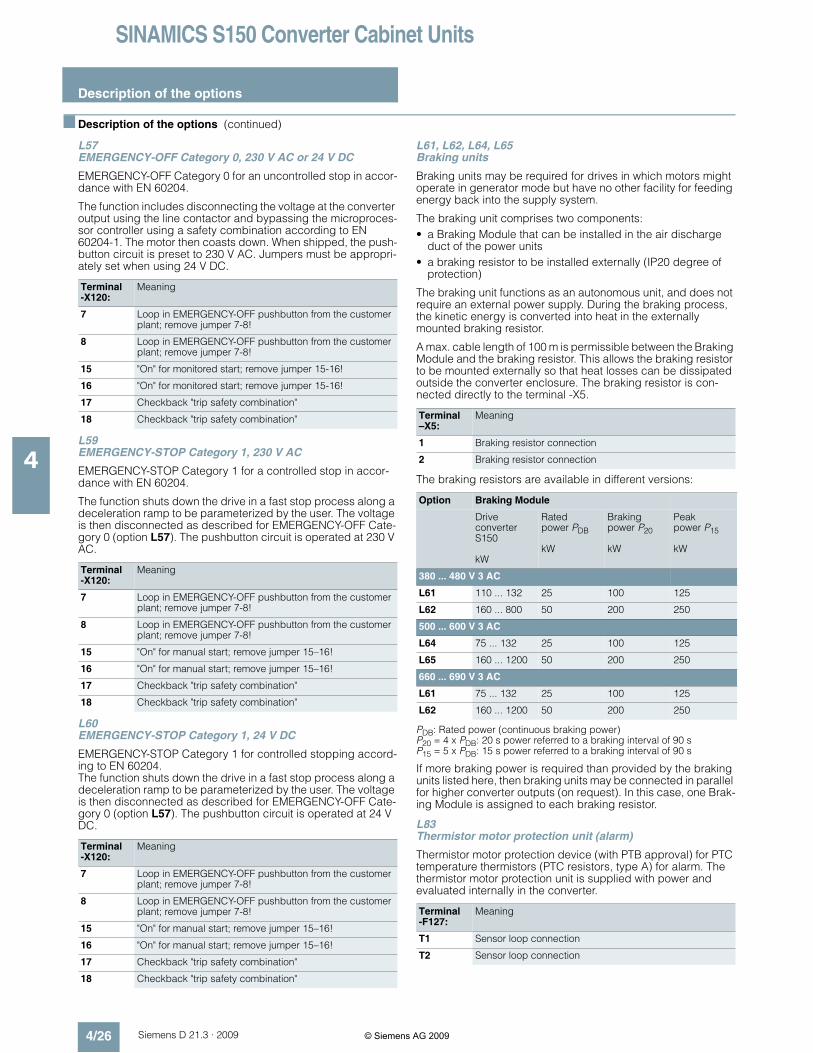
SINAMICS S150 Converter Cabinet Units
Description of the options
4/26 Siemens D 21.3 · 2009
4
! Description of the options (continued)
L57EMERGENCY-OFF Category 0, 230 V AC or 24 V DC
EMERGENCY-OFF Category 0 for an uncontrolled stop in accor-dance with EN 60204.
The function includes disconnecting the voltage at the converteroutput using the line contactor and bypassing the microproces-sor controller using a safety combination according to EN60204-1. The motor then coasts down. When shipped, the push-button circuit is preset to 230 V AC. Jumpers must be appropri-ately set when using 24 V DC.
L59EMERGENCY-STOP Category 1, 230 V AC
EMERGENCY-STOP Category 1 for a controlled stop in accor-dance with EN 60204.
The function shuts down the drive in a fast stop process along adeceleration ramp to be parameterized by the user. The voltageis then disconnected as described for EMERGENCY-OFF Cate-gory 0 (option L57). The pushbutton circuit is operated at 230 VAC.
L60EMERGENCY-STOP Category 1, 24 V DC
EMERGENCY-STOP Category 1 for controlled stopping accord-ing to EN 60204.The function shuts down the drive in a fast stop process along adeceleration ramp to be parameterized by the user. The voltageis then disconnected as described for EMERGENCY-OFF Cate-gory 0 (option L57). The pushbutton circuit is operated at 24 VDC.
L61, L62, L64, L65Braking units
Braking units may be required for drives in which motors mightoperate in generator mode but have no other facility for feedingenergy back into the supply system.
The braking unit comprises two components:
• a Braking Module that can be installed in the air dischargeduct of the power units
• a braking resistor to be installed externally (IP20 degree ofprotection)
The braking unit functions as an autonomous unit, and does notrequire an external power supply. During the braking process,the kinetic energy is converted into heat in the externallymounted braking resistor.
A max. cable length of 100 m is permissible between the BrakingModule and the braking resistor. This allows the braking resistorto be mounted externally so that heat losses can be dissipatedoutside the converter enclosure. The braking resistor is con-nected directly to the terminal -X5.
The braking resistors are available in different versions:
PDB: Rated power (continuous braking power)P20 = 4 x PDB: 20 s power referred to a braking interval of 90 sP15 = 5 x PDB: 15 s power referred to a braking interval of 90 s
If more braking power is required than provided by the brakingunits listed here, then braking units may be connected in parallelfor higher converter outputs (on request). In this case, one Brak-ing Module is assigned to each braking resistor.
L83Thermistor motor protection unit (alarm)
Thermistor motor protection device (with PTB approval) for PTCtemperature thermistors (PTC resistors, type A) for alarm. Thethermistor motor protection unit is supplied with power andevaluated internally in the converter.
Terminal-X120:
Meaning
7 Loop in EMERGENCY-OFF pushbutton from the customerplant; remove jumper 7-8!
8 Loop in EMERGENCY-OFF pushbutton from the customerplant; remove jumper 7-8!
15 "On" for monitored start; remove jumper 15-16!
16 "On" for monitored start; remove jumper 15-16!
17 Checkback "trip safety combination"
18 Checkback "trip safety combination"
Terminal-X120:
Meaning
7 Loop in EMERGENCY-OFF pushbutton from the customerplant; remove jumper 7-8!
8 Loop in EMERGENCY-OFF pushbutton from the customerplant; remove jumper 7-8!
15 "On" for manual start; remove jumper 15–16!
16 "On" for manual start; remove jumper 15–16!
17 Checkback "trip safety combination"
18 Checkback "trip safety combination"
Terminal–X5:
Meaning
1 Braking resistor connection
2 Braking resistor connection
Option Braking Module
DriveconverterS150
kW
Ratedpower PDB
kW
Brakingpower P20
kW
Peakpower P15
kW
380 ... 480 V 3 AC
L61 110 ... 132 25 100 125
L62 160 ... 800 50 200 250
500 ... 600 V 3 AC
L64 75 ... 132 25 100 125
L65 160 ... 1200 50 200 250
660 ... 690 V 3 AC
L61 75 ... 132 25 100 125
L62 160 ... 1200 50 200 250
Terminal-F127:
Meaning
T1 Sensor loop connection
T2 Sensor loop connection
© Siemens AG 2009

SINAMICS S150 Converter Cabinet Units
Description of the options
4/27Siemens D 21.3 · 2009
4
! Description of the options (continued)
L84Thermistor motor protection unit (trip)
Thermistor motor protection device (with PTB approval) for PTCthermistors temperature sensor (PTC resistors, type A) for trip.The thermistor motor protection unit is supplied with power andevaluated internally in the converter.
L86PT100 evaluation unit
The PT100 evaluation unit can monitor up to 6 sensors. Thesensors can be connected with two or three conductors to theevaluation unit. The limit values can be freely programmed foreach channel.In the factory setting, the measuring channels are divided intotwo groups each with 3 channels. With motors, for example, thismeans that three PT100s in the stator windings and two PT100sin the motor bearings can be monitored. Unused channels canbe suppressed via parameters.
The output relays are integrated into the internal fault and shut-down sequence of the converter. The customer can also tap theevent logs via two free fault signal relays. Two user-programma-ble analog outputs are also available (0/4 mA to 20 mA and0/2 V to 10 V) for integration in a higher-level control system.
L87Insulation monitoring
An insulation monitor must be used if the converter is operatedon an isolated-neutral system. The device monitors the entiregalvanically coupled circuit for insulation faults.
An alarm is output by the insulation monitor in the event of a fault.
Notice: Only one insulation monitor can be used in each galvan-ically coupled network.
The response concept in the event of a ground fault in the iso-lated-neutral system can vary, so output relays are available forlinking the monitor into a higher-level plant control. The customercan also choose to integrate the outputs into the convertermonitoring system.
M06Base 100 mm high, RAL 7022
The additional cabinet base allows larger bending radii forcables (cable inlet from below) and enables them to be routedwithin the cabinet base.
The cabinet base is supplied in RAL 7022 in all cases. A specialpaint finish is not available for the base. It is delivered completelyassembled with the cabinet. The mounting height of the operatorpanel changes accordingly.
M07Cable-marshaling compartment 200 mm high, RAL 7035
The cable-marshaling compartment is made of strong sheetsteel and allows cables to be connected more flexibly (entryfrom below). It also allows routing of cables within the marshalingcompartment. It is delivered completely assembled with thecabinet. The mounting height of the operator panel changes ac-cordingly.
Notice: The cable-marshaling compartment is painted as stan-dard with RAL 7035. If a special color is requested for the cabi-net (Order code Y09), the cable-marshaling compartment is alsopainted in this color.
Terminal-F125:
Meaning
T1 Sensor loop connection
T2 Sensor loop connection
Terminal-A1-A140:
Meaning
T11 to T13 PT100; sensor 1; group 1
T21 to T23 PT100; sensor 2; group 1
T31 to T33 PT100; sensor 3; group 1
T41 to T43 PT100; sensor 1; group 2
T51 to T53 PT100; sensor 2; group 2
T61 to T63 PT100; sensor 3, group 2
The sensors can be connected to the PT100 evaluation unit using atwo-wire or three-wire system.
The inputs Tx1 and Tx3 must be used for a two-wire system.With a three-wire system, input Tx2 must also be connected(x = 1, 2, ..., 6)
51, 52, 54 Relay outputLimit value for group 1 reached; (changeover contact)
61, 62, 64 Relay outputLimit value for group 2 reached; (changeover contact)
Ground(OUT 1)
Analog output OUT 1; group 1 sensor
U1 (OUT 1) Analog output OUT 1; group 1 sensor
I1 (OUT 1) Analog output OUT 1; group 1 sensor
Ground(OUT 2)
Analog output OUT 2; group 2 sensor
U2 (OUT 2) Analog output OUT 2; group 2 sensor
I2 (OUT 2) Analog output OUT 2; group 2 sensor
Terminal-A1-A101:
Meaning
11 Signaling relay ALARM 1 base
12 Signaling relay ALARM 1 NC contact
14 Signaling relay ALARM 1 NO contact
21 Signaling relay ALARM 2 base
22 Signaling relay ALARM 2 NC contacts
24 Signaling relay ALARM 2 NO contacts
M+ External kΩ display 0 µA to 400 µA
M- External kΩ display 0 µA to 400 µA
R1 External reset button (NC contact or wire jumper otherwisethe fault code is not stored)
R2 External reset button (NC contact or wire jumper)
T1 External test button
T2 External test button
© Siemens AG 2009

SINAMICS S150 Converter Cabinet Units
Description of the options
4/28 Siemens D 21.3 · 2009
4
! Description of the options (continued)
M13Line connection from above
The control cabinet is provided with an additional roof section toallow a line connection from above. The connecting lugs for thepower cables, the clamping bar for mechanically securing thecables, an EMC shield bus, and a PE busbar are located insidethe roof section.
This increases the cabinet height by 405 mm. The busbars forconnection from above are fully mounted when the cabinet isdelivered. For transport reasons, the roof sections are deliveredseparately and must be fitted on site. Crane transport assem-blies (option M90) can still be used. However, they must beremoved on site before the roof sections can be installed. Use ofrope spreaders should be considered in the case of small cranehook heights.
An undrilled aluminum mounting plate (5 mm thick) is providedin the roof section for feeding in the cables. Depending on thenumber of cables and the cross-sections used, holes for attach-ing cable glands for feeding in the cables must be drilled in thismounting plate on site.
Note: The control lines are still connected from below. OptionM13 eliminates the lugs, provided as standard, to connect theline supply from below.
The degree of protection of the roof sections is IP21. In combi-nation with options M23, M43 and M54, additional plastic venti-lation grilles and filter elements are provided.
Notice: The roof sections are painted in RAL 7035 as standard.If a special color is requested for the cabinet (order code Y09),the roof sections are also painted in this color. Ventilation grillesused with IP23 and IP54 degrees of protection have an RAL7035 color and cannot be painted.
The covers provided with option M60 are also included in thescope of supply.
M21IP21 degree of protection
Cabinet version in IP20, but with additional top or drip protectioncover. This increases the cabinet height by 250 mm.
For transport reasons, the top or drip protection covers are de-livered separately and must be fitted on site.
Notice: The top or drip protection covers are painted in RAL7035 as standard. If a special color is requested for the cabinet(order code Y09), the top or drip protection covers will also bepainted this color.
M23IP23 degree of protection
Converter cabinet units with IP23 degree of protection are sup-plied with additional roof sections and plastic ventilation grillesin the air inlet and outlet. This increases the cabinet height by400 mm. The covers provided with option M60 are also includedin the scope of supply.
For transport reasons, the roof sections are delivered separatelyand must be fitted on site.
Notice: The roof sections are colored RAL 7035 as standard. If aspecial color is requested for the cabinet (order code Y09), theroof sections are also painted in this color. The molded plasticparts (e.g. ventilation grilles) are colored RAL 7035 and cannotbe painted.
M43IP43 degree of protection
Converter cabinet units with IP43 degree of protection are sup-plied with additional roof sections as well as plastic ventilationgrilles and a wire mesh in the air inlet and outlet. This increasesthe cabinet height by 400 mm. The covers provided with optionM60 are also included in the scope of supply. They are an inte-gral component of the internal cabinet air guidance system andare adapted accordingly.
For transport reasons, the roof sections are delivered separatelyand must be fitted on site.
Notice: The roof sections are colored RAL 7035 as standard. If aspecial color is requested for the cabinet (order code Y09), theroof sections are also painted in this color. The molded plasticparts (e.g. ventilation grilles) are colored RAL 7035 and cannotbe painted.
M54IP54 degree of protection
Converter cabinet units with IP54 degree of protection aresupplied with additional roof sections as well as plastic ventila-tion grilles and a filter medium in the air inlet and outlet. This in-creases the cabinet height by 400 mm. The covers provided withoption M60 are also included in the scope of supply. They are anintegral component of the internal cabinet air guidance systemand are adapted accordingly. The filters must be maintainedaccording to the local environmental conditions.
Notice: With IP54 degree of protection, the derating factors forthe output current must be observed.
For transport reasons, the roof sections are delivered separatelyand must be fitted on site.
Notice: The roof sections are colored RAL 7035 as standard. If aspecial color is requested for the cabinet (order code Y09), theroof sections are also painted in this color. The molded plasticparts (e.g. ventilation grilles) are colored RAL 7035 and cannotbe painted.
M60Additional shock protection
The converter cabinet units are designed as standard accordingto BGV A3. Option M60 provides additional covers (outsidearm's reach) in the vicinity of the AC busbars and above thepower unit (can only be selected as an option with converters upto 250 kW in the 400 V range and with converters up to 315 kWin the 690 V range with degrees of protection IP20 and IP21;otherwise supplied as standard).
© Siemens AG 2009

SINAMICS S150 Converter Cabinet Units
Description of the options
4/29Siemens D 21.3 · 2009
4
! Description of the options (continued)
M66Marine version
For compliance with the requirements of the classificationinstitutes:
• Lloyds Register
• American Bureau of Shipping
• Germanischer Lloyd
• Bureau Veritas
• Det Norske Veritas
• Chinese Classification Society
This option includes a strengthened mechanical version ofthe cabinet, handles (handrail) below the operator panel andmechanical locking of the cabinet doors. The cabinet hasdegree of protection IP23 (M23 option) and includes a cabinetanti-condensation heater (L55 option). To attach the driveconverter to the ship's deck, a welding frame (5 mm high) issupplied separately.
Note: M66 cannot be combined with options M21, M23 and L55.Individual certification is additionally required if the converter isused for a safety-relevant drive on the ship (see options E11 toE71).
M70EMC shield bus (cable connection from below)
The EMC shield bus is used to connect shielded power cablesfor the line supply and motor feeder cables. With the optionsM13 and M78, the EMC shield bus is already included as stan-dard for the connection busbars underneath the roof section.
M78Motor connection from above
The control cabinet is provided with an additional roof section fora motor connection from above. The connecting lugs for thepower cables, the clamping bar for mechanically securing thecables, an EMC shield bus, and a PE busbar are located insidethe roof section.
This increases the cabinet height by 405 mm. The busbars forconnection from above are fully mounted when the cabinet is de-livered. For transport reasons, the roof sections are deliveredseparately and must be fitted on site. Crane transport assem-blies (option M90) can still be used. However, they must be re-moved on site before the roof sections can be installed. Use ofrope spreaders should be considered in the case of small cranehook heights.
An undrilled aluminum mounting plate (5 mm thick) is providedin the roof section for feeding in the cables. Depending on thenumber of cables and the cross-sections used, holes for attach-ing cable glands for feeding in the cables must be drilled in thismounting plate on site.
Note: The control cables are still connected from below. OptionM78 eliminates the lugs, provided as standard, to connect themotor from below.
The degree of protection of the roof sections is IP21. In combi-nation with options M23, M43 and M54, additional plastic venti-lation grilles and filter elements are provided.
Notice: The roof sections are painted in RAL 7035 as standard.If a special color is requested for the cabinet (order code Y09),the roof sections are also painted in this color. Ventilation grillesused with IP23 and IP54 degrees of protection have an RAL7035 color and cannot be painted.
The covers provided with option M60 are also included in thescope of supply.
M90Crane transport assembly (top-mounted)
In the case of single cabinets up to a width of 600 mm, transporteyebolts are provided to transport the unit by crane. For cabinetwidths of 800 mm and wider, transport rails are used.
T58, T60, T80Rating plate data
The standard version of the rating plate is English/German.A rating plate in another language can be selected by specifyingthe following option order codes.
Y09Special cabinet paint coating
The converter cabinet units are painted with RAL 7035 as stan-dard. The special paint finish must be stated in plain text in theorder. All RAL colors which are available as powder coatingscan be selected. If options such as cable-marshaling compart-ment (order code M07), top or drip protection covers (ordercode M21), roof sections (order codes M23/M43/M54) or cableconnection from above (order codes M13/M78) are ordered forthe converter cabinet units, they will also be supplied in the paintfinish stated in the order. The molded plastic parts (e.g. ventila-tion grilles) are colored RAL 7035 and cannot be painted.
Order code Rating plate language
T58 English / French
T60 English / Spanish
T80 English / Italian
© Siemens AG 2009

SINAMICS S150 Converter Cabinet Units
Line-side components
4/30 Siemens D 21.3 · 2009
4
! Overview
The fuses specified below are the recommended types for pro-tecting the unit on the low-voltage distribution panel.If option L26 was selected for SINAMICS S150 with rated inputcurrents < 800 A, then the semiconductor protection is alreadyintegrated in the unit. For units > 800 A, this function is realizedby the circuit breaker provided as standard. In this case, a 3NAfuse can be used in the distribution system. If option L26 has not
been selected for units < 800 A, then we strongly advise that3NE fuses are used. 1)
Further information on the listed fuses and circuit breakers canbe found in Catalogs LV 1 and LV 1 T.
Type rating Drive converterSINAMICS S150
Cable protection fusein systems with fuse switch disconnector
Cable protection fuse(incl. semiconductor protection)in systems without fuse switch disconnector
at 50 Hz400 V, 500 Vor 690 V
at 60 Hz460 V or575 V
Rated current Rated current
kW hp 6SL3710-... Order No. A Frame sizeacc. toDIN 43620-1
Order No. A Frame sizeacc. toDIN 43620-1
Line voltage 380 ... 480 V 3 AC
110 150 7LE32-1AA0 3NA3 252 315 2 3NE1 230-2 315 1
132 200 7LE32-6AA0 3NA3 254 355 2 3NE1 331-2 350 2
160 250 7LE33-1AA0 3NA3 365 500 3 3NE1 334-2 500 2
200 300 7LE33-8AA0 3NA3 365 500 3 3NE1 334-2 500 2
250 400 7LE35-0AA0 3NA3 372 630 3 3NE1 436-2 630 3
315 500 7LE36-1AA0 3NA3 475 800 4 3NE1 438-2 800 3
400 600 7LE37-5AA0 3NA3 475 800 4 3NE1 448-2 850 3
450 700 7LE38-4AA0 - - - Circuit breaker as standard
560 800 7LE41-0AA0 - - - Circuit breaker as standard
710 1000 7LE41-2AA0 - - - Circuit breaker as standard
800 1000 7LE41-4AA0 - - - Circuit breaker as standard
Line voltage 500 ... 690 V 3 AC
75 75 7LG28-5AA0 3NA3 132-6 125 1 3NE1 022-2 125 00
90 75 7LG31-0AA0 3NA3 132-6 125 1 3NE1 022-2 125 00
110 100 7LG31-2AA0 3NA3 136-6 160 1 3NE1 224-2 160 1
132 150 7LG31-5AA0 3NA3 240-6 200 2 3NE1 225-2 200 1
160 150 7LG31-8AA0 3NA3 244-6 250 2 3NE1 227-2 250 1
200 200 7LG32-2AA0 3NA3 252-6 315 2 3NE1 230-2 315 1
250 250 7LG32-6AA0 3NA3 354-6 355 3 3NE1 331-2 350 2
315 300 7LG33-3AA0 3NA3 365-6 500 3 3NE1 334-2 500 2
400 400 7LG34-1AA0 3NA3 365-6 500 3 3NE1 334-2 500 2
450 450 7LG34-7AA0 3NA3 352-6 2x315 2 3NE1 435-2 560 3
560 600 7LG35-8AA0 3NA3 354-6 2x355 3 3NE1 447-2 670 3
710 700 7LG37-4AA0 3NA3 365-6 2x500 3 3NE1 448-2 850 3
800 800 7LG38-1AA0 - - - Circuit breaker as standard
900 900 7LG38-8AA0 - - - Circuit breaker as standard
1000 1000 7LG41-0AA0 - - - Circuit breaker as standard
1200 1250 7LG41-3AA0 - - - Circuit breaker as standard
1) The double function fuses (3NE1.) with duty class gS for cable and semi-conductor protection are recommended to protect the converter. Thesefuses are specially adapted to the requirements of the semiconductorsin the input rectifier.
- super fast
- adapted to the limit current integral of the semiconductor
- lower arc voltage
- improved current limiting (lower let-through values).
© Siemens AG 2009