Embed Size (px)
Citation preview


SINAMICS G120D converter with control
units CU240D-2 and CU250D-2
___________________
___________________
___________________
___________________
___________________
SINAMICS
SINAMICS G120D SINAMICS G120D converter with control units CU240D-2 and CU250D-2 Getting Started
Edition 04/2014, firmware V4.7
04/2014, FW V4.7 A5E34262374B AA
Fundamental safety instructions
1
Introduction 2
Installation 3
Commissioning 4
Troubleshooting 5

Siemens AG Industry Sector Postfach 48 48 90026 NÜRNBERG GERMANY
A5E34262374B AA Ⓟ 05/2014 Subject to change
Copyright © Siemens AG 2012 - 2014. All rights reserved
Legal information Warning notice system
This manual contains notices you have to observe in order to ensure your personal safety, as well as to prevent damage to property. The notices referring to your personal safety are highlighted in the manual by a safety alert symbol, notices referring only to property damage have no safety alert symbol. These notices shown below are graded according to the degree of danger.
DANGER indicates that death or severe personal injury will result if proper precautions are not taken.
WARNING indicates that death or severe personal injury may result if proper precautions are not taken.
CAUTION indicates that minor personal injury can result if proper precautions are not taken.
NOTICE indicates that property damage can result if proper precautions are not taken.
If more than one degree of danger is present, the warning notice representing the highest degree of danger will be used. A notice warning of injury to persons with a safety alert symbol may also include a warning relating to property damage.
Qualified Personnel The product/system described in this documentation may be operated only by personnel qualified for the specific task in accordance with the relevant documentation, in particular its warning notices and safety instructions. Qualified personnel are those who, based on their training and experience, are capable of identifying risks and avoiding potential hazards when working with these products/systems.
Proper use of Siemens products Note the following:
WARNING Siemens products may only be used for the applications described in the catalog and in the relevant technical documentation. If products and components from other manufacturers are used, these must be recommended or approved by Siemens. Proper transport, storage, installation, assembly, commissioning, operation and maintenance are required to ensure that the products operate safely and without any problems. The permissible ambient conditions must be complied with. The information in the relevant documentation must be observed.
Trademarks All names identified by ® are registered trademarks of Siemens AG. The remaining trademarks in this publication may be trademarks whose use by third parties for their own purposes could violate the rights of the owner.
Disclaimer of Liability We have reviewed the contents of this publication to ensure consistency with the hardware and software described. Since variance cannot be precluded entirely, we cannot guarantee full consistency. However, the information in this publication is reviewed regularly and any necessary corrections are included in subsequent editions.

SINAMICS G120D converter with control units CU240D-2 and CU250D-2 Getting Started, 04/12014, FW V4.7, A5E34262374B AA 5
Table of contents
1 Fundamental safety instructions .............................................................................................................. 7
1.1 General safety instructions ............................................................................................................ 7
1.2 Safety instructions for electromagnetic fields (EMF) ................................................................... 11
1.3 Handling electrostatic sensitive devices (ESD) ........................................................................... 11
1.4 Industrial security ......................................................................................................................... 12
1.5 Residual risks of power drive systems ......................................................................................... 13
2 Introduction ........................................................................................................................................... 15
2.1 SINAMICS G120D converter ....................................................................................................... 15
2.2 Commissioning tools .................................................................................................................... 17
3 Installation ............................................................................................................................................ 19
3.1 Fitting the CU to the PM ............................................................................................................... 19
3.2 Drill pattern SINAMICS G120D .................................................................................................... 20
3.3 Overview of the interfaces ........................................................................................................... 22
3.4 Electrical data ............................................................................................................................... 23
3.5 Basic EMC Rules ......................................................................................................................... 24
3.6 Connections and cables ............................................................................................................... 25
3.7 Default settings of inputs and outputs .......................................................................................... 39
3.8 Settings PROFIBUS DP address with DIP switches ................................................................... 41
3.9 Connecting the PROFINET interface ........................................................................................... 42
3.10 Grounding converter and motor ................................................................................................... 42
3.11 Connections and interference suppression ................................................................................. 44
3.12 Equipotential bonding .................................................................................................................. 44
4 Commissioning ..................................................................................................................................... 47
4.1 Default settings for the SINAMICS G120D .................................................................................. 47
4.2 Commissioning with the IOP ........................................................................................................ 48
4.3 Commissioning the application .................................................................................................... 53
4.4 Reset Parameters to Factory Settings ......................................................................................... 54
5 Troubleshooting .................................................................................................................................... 55
5.1 List of alarms and faults ............................................................................................................... 55
5.2 Status LED overview .................................................................................................................... 61
5.3 Further information ....................................................................................................................... 63

Table of contents
SINAMICS G120D converter with control units CU240D-2 and CU250D-2 6 Getting Started, 04/12014, FW V4.7, A5E34262374B AA
Objective of these instructions This Getting Started describes how you install an inverter and commission and operate it using the IOP operator panel.
The functions and properties of the IOP are described in detail in the "SINAMICS IOP" operating instructions and are only explained here to an extent that is necessary to understand the described functions.
Additional information on SINAMICS G120
All manuals for the inverter can be downloaded from the Internet and are additionally available on DVD. See also Section: Further information (Page 63).
What is the meaning of the symbols in the manual?
An operating instruction starts here.
This concludes the operating instruction.
Firmware upgrade and downgrade Options for upgrading and downgrading the firmware can be found on the Internet at http://support.automation.siemens.com/WW/view/de/67364620 (http://support.automation.siemens.com/WW/news/en/67364620).
Transferring license terms of the OSS code to a PC
Procedure
To transfer the OSS license terms from the inverter to a PC, proceed as follows:
1. Switch off the inverter power supply.
2. Insert an empty memory card into the card slot of the inverter. Also see Section:Overview of the interfaces (Page 22)
3. Switch on the inverter power supply.
4. When you have switched on the power supply, wait 30 seconds.
During this time, the inverter writes the "Read_OSS.ZIP" file onto the memory card.
5. Switch off the inverter power supply.
6. Remove the card from the inverter.
7. Use a card reader and load the file to a PC.
You have then transferred the OSS license terms from the inverter to a PC.
SINAMICS G120D converter with control units CU240D-2 and CU250D-2 Getting Started, 04/12014, FW V4.7, A5E34262374B AA 7
Fundamental safety instructions 1 1.1 General safety instructions
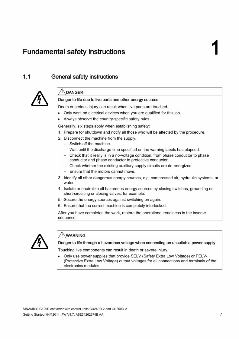
DANGER
Danger to life due to live parts and other energy sources
Death or serious injury can result when live parts are touched. • Only work on electrical devices when you are qualified for this job. • Always observe the country-specific safety rules.
Generally, six steps apply when establishing safety: 1. Prepare for shutdown and notify all those who will be affected by the procedure. 2. Disconnect the machine from the supply.
– Switch off the machine. – Wait until the discharge time specified on the warning labels has elapsed. – Check that it really is in a no-voltage condition, from phase conductor to phase
conductor and phase conductor to protective conductor. – Check whether the existing auxiliary supply circuits are de-energized. – Ensure that the motors cannot move.
3. Identify all other dangerous energy sources, e.g. compressed air, hydraulic systems, or water.
4. Isolate or neutralize all hazardous energy sources by closing switches, grounding or short-circuiting or closing valves, for example.
5. Secure the energy sources against switching on again. 6. Ensure that the correct machine is completely interlocked.
After you have completed the work, restore the operational readiness in the inverse sequence.
WARNING
Danger to life through a hazardous voltage when connecting an unsuitable power supply
Touching live components can result in death or severe injury. • Only use power supplies that provide SELV (Safety Extra Low Voltage) or PELV-
(Protective Extra Low Voltage) output voltages for all connections and terminals of the electronics modules.

Fundamental safety instructions 1.1 General safety instructions
SINAMICS G120D converter with control units CU240D-2 and CU250D-2 8 Getting Started, 04/12014, FW V4.7, A5E34262374B AA
WARNING
Danger to life when live parts are touched on damaged devices
Improper handling of devices can cause damage.
For damaged devices, hazardous voltages can be present at the enclosure or at exposed components; if touched, this can result in death or severe injury. • Ensure compliance with the limit values specified in the technical data during transport,
storage and operation. • Do not use any damaged devices.
WARNING
Danger to life through electric shock due to unconnected cable shields
Hazardous touch voltages can occur through capacitive cross-coupling due to unconnected cable shields. • As a minimum, connect cable shields and the conductors of power cables that are not
used (e.g. brake cores) at one end at the grounded housing potential.
WARNING
Danger to life due to electric shock when not grounded
For missing or incorrectly implemented protective conductor connection for devices with protection class I, high voltages can be present at open, exposed parts, which when touched, can result in death or severe injury. • Ground the device in compliance with the applicable regulations.
WARNING
Danger to life due to electric shock when opening plug connections in operation
When opening plug connections in operation, arcs can result in severe injury or death. • Only open plug connections when the equipment is in a no-voltage state, unless it has
been explicitly stated that they can be opened in operation.
WARNING
Danger to life due to fire spreading if housing is inadequate
Fire and smoke development can cause severe personal injury or material damage. • Install devices without a protective housing in a metal control cabinet (or protect the
device by another equivalent measure) in such a way that contact with fire is prevented. • Ensure that smoke can only escape via controlled and monitored paths.

Fundamental safety instructions 1.1 General safety instructions
SINAMICS G120D converter with control units CU240D-2 and CU250D-2 Getting Started, 04/12014, FW V4.7, A5E34262374B AA 9
WARNING
Danger to life through unexpected movement of machines when using mobile wireless devices or mobile phones
Using mobile wireless devices or mobile phones with a transmit power > 1 W closer than approx. 2 m to the components may cause the devices to malfunction, influence the functional safety of machines therefore putting people at risk or causing material damage. • Switch the wireless devices or mobile phones off in the immediate vicinity of the
components.
WARNING
Danger to life due to the motor catching fire in the event of insulation overload
There is higher stress on the motor insulation through a ground fault in an IT system. If the insulation fails, it is possible that death or severe injury can occur as a result of smoke and fire. • Use a monitoring device that signals an insulation fault. • Correct the fault as quickly as possible so the motor insulation is not overloaded.
WARNING
Danger to life due to fire if overheating occurs because of insufficient ventilation clearances
Inadequate ventilation clearances can cause overheating of components with subsequent fire and smoke. This can cause severe injury or even death. This can also result in increased downtime and reduced service lives for devices/systems. • Ensure compliance with the specified minimum clearance as ventilation clearance for
the respective component.
WARNING
Danger of an accident occurring due to missing or illegible warning labels
Missing or illegible warning labels can result in accidents involving death or serious injury. • Check that the warning labels are complete based on the documentation. • Attach any missing warning labels to the components, in the national language if
necessary. • Replace illegible warning labels.

Fundamental safety instructions 1.1 General safety instructions
SINAMICS G120D converter with control units CU240D-2 and CU250D-2 10 Getting Started, 04/12014, FW V4.7, A5E34262374B AA
NOTICE
Device damage caused by incorrect voltage/insulation tests
Incorrect voltage/insulation tests can damage the device. • Before carrying out a voltage/insulation check of the system/machine, disconnect the
devices as all converters and motors have been subject to a high voltage test by the manufacturer, and therefore it is not necessary to perform an additional test within the system/machine.
WARNING
Danger to life when safety functions are inactive
Safety functions that are inactive or that have not been adjusted accordingly can cause operational faults on machines that could lead to serious injury or death. • Observe the information in the appropriate product documentation before
commissioning. • Carry out a safety inspection for functions relevant to safety on the entire system,
including all safety-related components. • Ensure that the safety functions used in your drives and automation tasks are adjusted
and activated through appropriate parameterizing. • Perform a function test. • Only put your plant into live operation once you have guaranteed that the functions
relevant to safety are running correctly.
Note Important safety notices for Safety Integrated functions
If you want to use Safety Integrated functions, you must observe the safety notices in the Safety Integrated manuals.
WARNING
Danger to life or malfunctions of the machine as a result of incorrect or changed parameterization
As a result of incorrect or changed parameterization, machines can malfunction, which in turn can lead to injuries or death. • Protect the parameterization (parameter assignments) against unauthorized access. • Respond to possible malfunctions by applying suitable measures (e.g. EMERGENCY
STOP or EMERGENCY OFF).

Fundamental safety instructions 1.2 Safety instructions for electromagnetic fields (EMF)
SINAMICS G120D converter with control units CU240D-2 and CU250D-2 Getting Started, 04/12014, FW V4.7, A5E34262374B AA 11
1.2 Safety instructions for electromagnetic fields (EMF)
WARNING
Danger to life from electromagnetic fields
Electromagnetic fields (EMF) are generated by the operation of electrical power equipment such as transformers, converters or motors.
People with pacemakers or implants are at a special risk in the immediate vicinity of these devices/systems. • Ensure that the persons involved are the necessary distance away (minimum 2 m).
1.3 Handling electrostatic sensitive devices (ESD) Electrostatic sensitive devices (ESD) are individual components, integrated circuits, modules or devices that may be damaged by either electric fields or electrostatic discharge.
NOTICE
Damage through electric fields or electrostatic discharge
Electric fields or electrostatic discharge can cause malfunctions through damaged individual components, integrated circuits, modules or devices. • Only pack, store, transport and send electronic components, modules or devices in their
original packaging or in other suitable materials, e.g conductive foam rubber of aluminum foil.
• Only touch components, modules and devices when you are grounded by one of the following methods: – Wearing an ESD wrist strap – Wearing ESD shoes or ESD grounding straps in ESD areas with conductive flooring
• Only place electronic components, modules or devices on conductive surfaces (table with ESD surface, conductive ESD foam, ESD packaging, ESD transport container).

Fundamental safety instructions 1.4 Industrial security
SINAMICS G120D converter with control units CU240D-2 and CU250D-2 12 Getting Started, 04/12014, FW V4.7, A5E34262374B AA
1.4 Industrial security
Note Industrial security
Siemens provides products and solutions with industrial security functions that support the secure operation of plants, solutions, machines, equipment and/or networks. They are important components in a holistic industrial security concept. With this in mind, Siemens’ products and solutions undergo continuous development. Siemens recommends strongly that you regularly check for product updates.
For the secure operation of Siemens products and solutions, it is necessary to take suitable preventive action (e.g. cell protection concept) and integrate each component into a holistic, state-of-the-art industrial security concept. Third-party products that may be in use should also be considered. For more information about industrial security, visit Hotspot-Text (http://www.siemens.com/industrialsecurity).
To stay informed about product updates as they occur, sign up for a product-specific newsletter. For more information, visit Hotspot-Text (http://support.automation.siemens.com).
WARNING
Danger as a result of unsafe operating states resulting from software manipulation
Software manipulation (e.g. by viruses, Trojan horses, malware, worms) can cause unsafe operating states to develop in your installation which can result in death, severe injuries and/or material damage. • Keep the software up to date.
You will find relevant information and newsletters at this address (http://support.automation.siemens.com).
• Incorporate the automation and drive components into a holistic, state-of-the-art industrial security concept for the installation or machine. You will find further information at this address (http://www.siemens.com/industrialsecurity).
• Make sure that you include all installed products into the holistic industrial security concept.

Fundamental safety instructions 1.5 Residual risks of power drive systems
SINAMICS G120D converter with control units CU240D-2 and CU250D-2 Getting Started, 04/12014, FW V4.7, A5E34262374B AA 13
1.5 Residual risks of power drive systems The control and drive components of a drive system are approved for industrial and commercial use in industrial line supplies. Their use in public line supplies requires a different configuration and/or additional measures.
These components may only be operated in closed housings or in higher-level control cabinets with protective covers that are closed, and when all of the protective devices are used.
These components may only be handled by qualified and trained technical personnel who are knowledgeable and observe all of the safety instructions on the components and in the associated technical user documentation.
When assessing the machine's risk in accordance with the respective local regulations (e.g., EC Machinery Directive), the machine manufacturer must take into account the following residual risks emanating from the control and drive components of a drive system:
1. Unintentional movements of driven machine components during commissioning, operation, maintenance, and repairs caused by, for example,
– Hardware and/or software errors in the sensors, control system, actuators, and cables and connections
– Response times of the control system and of the drive
– Operation and/or environmental conditions outside the specification
– Condensation/conductive contamination
– Parameterization, programming, cabling, and installation errors
– Use of wireless devices/mobile phones in the immediate vicinity of the control system
– External influences/damage
2. In the event of a fault, exceptionally high temperatures, including an open fire, as well as emissions of light, noise, particles, gases, etc. can occur inside and outside the inverter, e.g.:
– Component failure
– Software errors
– Operation and/or environmental conditions outside the specification
– External influences/damage
Inverters of the Open Type/IP20 degree of protection must be installed in a metal control cabinet (or protected by another equivalent measure) such that contact with fire inside and outside the inverter is not possible.

Fundamental safety instructions 1.5 Residual risks of power drive systems
SINAMICS G120D converter with control units CU240D-2 and CU250D-2 14 Getting Started, 04/12014, FW V4.7, A5E34262374B AA
3. Hazardous shock voltages caused by, for example,
– Component failure
– Influence during electrostatic charging
– Induction of voltages in moving motors
– Operation and/or environmental conditions outside the specification
– Condensation/conductive contamination
– External influences/damage
4. Electrical, magnetic and electromagnetic fields generated in operation that can pose a risk to people with a pacemaker, implants or metal replacement joints, etc., if they are too close
5. Release of environmental pollutants or emissions as a result of improper operation of the system and/or failure to dispose of components safely and correctly
Note
The components must be protected against conductive contamination (e.g. by installing them in a control cabinet with degree of protection IP54 according to IEC 60529 or NEMA 12).
Assuming that conductive contamination at the installation site can definitely be excluded, a lower degree of cabinet protection may be permitted.
For more information about residual risks of the components in a drive system, see the relevant sections in the technical user documentation.

SINAMICS G120D converter with control units CU240D-2 and CU250D-2 Getting Started, 04/12014, FW V4.7, A5E34262374B AA 15
Introduction 2 2.1 SINAMICS G120D converter
Overview The SINAMICS G120D is a range of converters for controlling the speed of three-phase motors. The converter consists of two parts, the Control Unit and the Power Module.
Table 2- 1 Control Units of the SINAMICS G120D converter
Designation Order number Encoder type Field bus
CU240D-2 DP 6SL3544-0FB20-1PA0 HTL Encoder PROFIBUS CU240D-2 DP-F 6SL3544-0FB21-1PA0 CU250D-2 DP-F 6SL3546-0FB21-1PA0 HTL Encoder
SSI Absolute Encoder CU240D-2 PN 6SL3544-0FB20-1FA0 HTL Encoder PROFINET,
EtherNet/IP CU240D-2 PN-F 6SL3544-0FB21-1FA0 CU250D-2 PN-F 6SL3546-0FB21-1FA0 HTL Encoder
SSI Absolute Encoder
CU240D-2 PN-F PP Push-Pull connections
6SL3544-0FB21-1FB0 HTL Encoder
CU240D-2 PN-F FO Fibre optic connections
6SL3544-0FB21-1FC0
CU250D-2 PN-F PP Push-Pull connections
6SL3546-0FB21-1FB0 HTL Encoder SSI Absolute Encoder
CU250D-2 PN-F FO Fibre optic connections
6SL3546-0FB21-1FC0

Introduction 2.1 SINAMICS G120D converter
SINAMICS G120D converter with control units CU240D-2 and CU250D-2 16 Getting Started, 04/12014, FW V4.7, A5E34262374B AA
Table 2- 2 PM250D Power Modules for the SINAMICS G120D converter
Frame size
Rated output power
Rated output current
Order number
based on High Overload (HO)
FSA 0.75 kW 2.2 A 6SL3525-0PE17-5AA1 1.5 kW 4.1 A 6SL3525-0PE21-5AA1
FSB 3.0 kW 7.7 A 6SL3525-0PE23-0AA1
FSC 4.0 kW 10.2 A 6SL3525-0PE24-0AA1 5.5 kW 13.2 A 6SL3525-0PE25-5AA1 7.5 kW 19.0 A 6SL3525-0PE27-5AA1

Introduction 2.2 Commissioning tools
SINAMICS G120D converter with control units CU240D-2 and CU250D-2 Getting Started, 04/12014, FW V4.7, A5E34262374B AA 17
2.2 Commissioning tools
Figure 2-1 Commissioning tools - PC or IOP Handheld Kit

Introduction 2.2 Commissioning tools
SINAMICS G120D converter with control units CU240D-2 and CU250D-2 18 Getting Started, 04/12014, FW V4.7, A5E34262374B AA
Table 2- 3 Components and tools for commissioning
Component or tool Order number Operator Panel IOP Handheld 6SL3255-0AA00-4HA0 STARTER Commissioning tool (PC
software) You obtain STARTER on a DVD (Order number: 6SL3072-0AA00-0AG0) and it can be downloaded: STARTER Download (http://support.automation.siemens.com/WW/view/en/26233208)
PC Connection Kit Comprising USB cable (3 m). 6SL3255-0AA00-2CA0

SINAMICS G120D converter with control units CU240D-2 and CU250D-2 Getting Started, 04/12014, FW V4.7, A5E34262374B AA 19
Installation 3 3.1 Fitting the CU to the PM
Fitting the Control Unit to the Power Module The inverter is delivered as two separate components - the Power Module (PM) and the Control Unit (CU). The CU must be fitted to the PM prior to any further commissioning taking place.
CAUTION
Seals fitted correctly
It is important that when assembling the Power Module and the Control Unit that all the seals are fitted correctly to ensure IP65 rating. TN and TT mains supplies
The SINAMICS PM250D Power Module with the Class A integrated mains filter is only suitable for operation on TN and TT mains supplies.
The CU is fitted to the PM as shown in the diagram below.
Figure 3-1 Fitting the Control Unit to the Power Module

Installation 3.2 Drill pattern SINAMICS G120D
SINAMICS G120D converter with control units CU240D-2 and CU250D-2 20 Getting Started, 04/12014, FW V4.7, A5E34262374B AA
3.2 Drill pattern SINAMICS G120D
Drill pattern and dimensions The inverter has an identical drill pattern for all frame sizes. The drill pattern, depth and tightening torques are shown in the diagram below.
Figure 3-2 SINAMICS G120D drill pattern

Installation 3.2 Drill pattern SINAMICS G120D
SINAMICS G120D converter with control units CU240D-2 and CU250D-2 Getting Started, 04/12014, FW V4.7, A5E34262374B AA 21
Mounting orientation Mount the converter on a table or on a wall. The minimum clearance distances are as follows:
● Side-by-side - no clearance distance is required
● Above and below the inverter 150 mm (5.9 inches).
Figure 3-3 Mounting orientation: correct (✓), impermissible (X), permissible with restrictions (!)
Restrictions due to vertical mounting If the converter is mounted in the vertical position, the maximum ambient temperature is 40°C.
Additionally you have to reduce the converter output current to 80 % of rated converter current.
If the output current derating adversely affects the application, you have to use an converter of the next highest power rating.
Installation 3.3 Overview of the interfaces
SINAMICS G120D converter with control units CU240D-2 and CU250D-2 22 Getting Started, 04/12014, FW V4.7, A5E34262374B AA
3.3 Overview of the interfaces
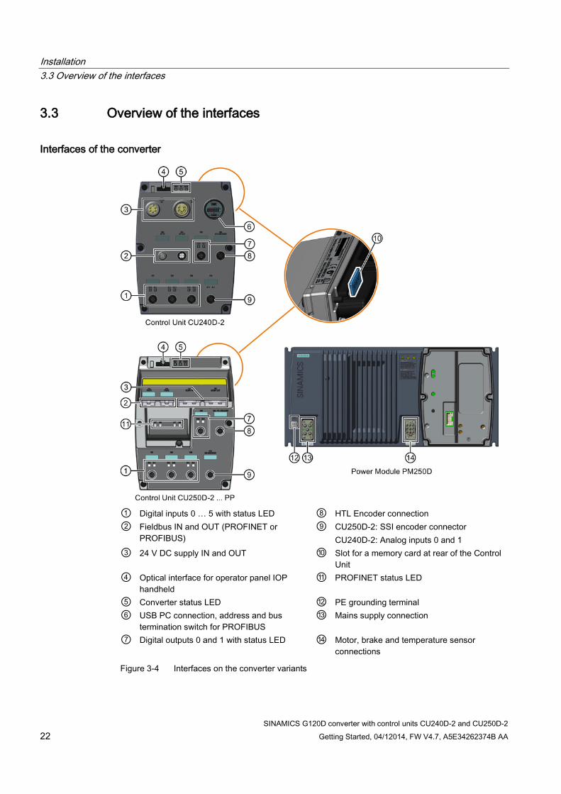
Interfaces of the converter
① Digital inputs 0 … 5 with status LED ⑧ HTL Encoder connection ② Fieldbus IN and OUT (PROFINET or
PROFIBUS) ⑨ CU250D-2: SSI encoder connector
CU240D-2: Analog inputs 0 and 1 ③ 24 V DC supply IN and OUT ⑩ Slot for a memory card at rear of the Control
Unit ④ Optical interface for operator panel IOP
handheld ⑪ PROFINET status LED
⑤ Converter status LED ⑫ PE grounding terminal ⑥ USB PC connection, address and bus
termination switch for PROFIBUS ⑬ Mains supply connection
⑦ Digital outputs 0 and 1 with status LED ⑭ Motor, brake and temperature sensor connections
Figure 3-4 Interfaces on the converter variants
Installation 3.4 Electrical data
SINAMICS G120D converter with control units CU240D-2 and CU250D-2 Getting Started, 04/12014, FW V4.7, A5E34262374B AA 23
3.4 Electrical data
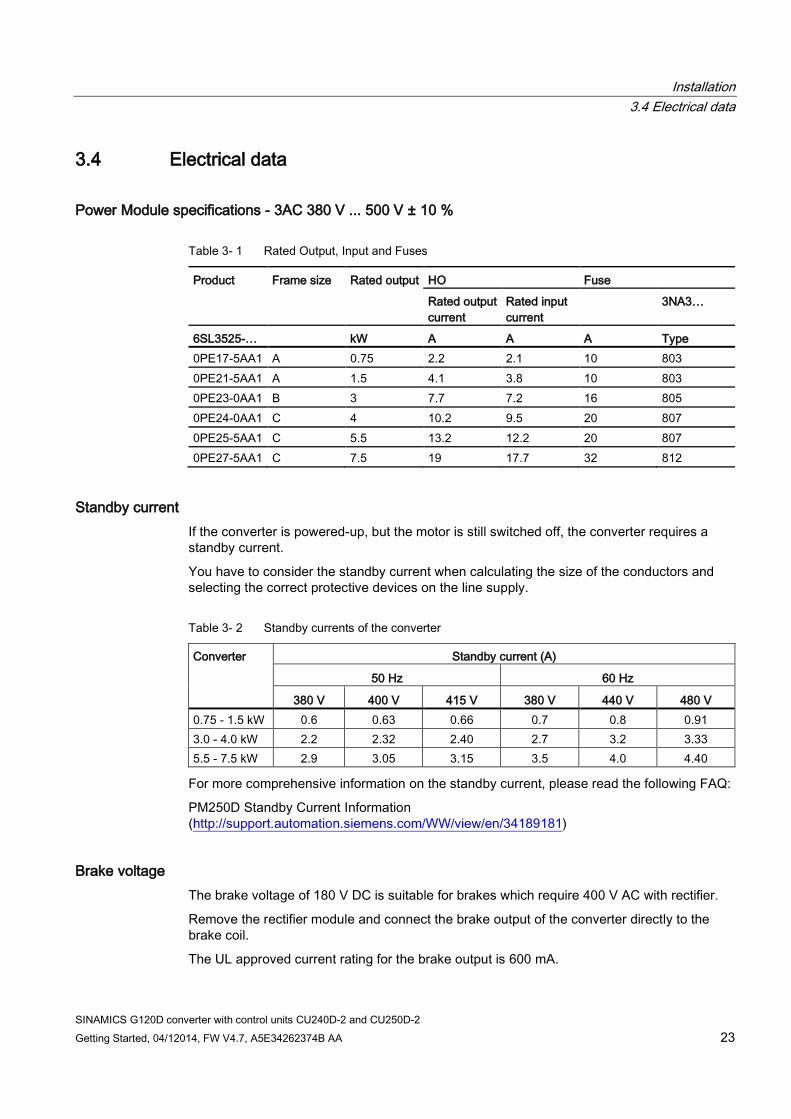
Power Module specifications - 3AC 380 V ... 500 V ± 10 %
Table 3- 1 Rated Output, Input and Fuses
Product Frame size Rated output HO Fuse
Rated output current
Rated input current
3NA3…
6SL3525-… kW A A A Type 0PE17-5AA1 A 0.75 2.2 2.1 10 803 0PE21-5AA1 A 1.5 4.1 3.8 10 803 0PE23-0AA1 B 3 7.7 7.2 16 805 0PE24-0AA1 C 4 10.2 9.5 20 807 0PE25-5AA1 C 5.5 13.2 12.2 20 807 0PE27-5AA1 C 7.5 19 17.7 32 812
Standby current If the converter is powered-up, but the motor is still switched off, the converter requires a standby current.
You have to consider the standby current when calculating the size of the conductors and selecting the correct protective devices on the line supply.
Table 3- 2 Standby currents of the converter
Converter Standby current (A)
50 Hz 60 Hz
380 V 400 V 415 V 380 V 440 V 480 V 0.75 - 1.5 kW 0.6 0.63 0.66 0.7 0.8 0.91 3.0 - 4.0 kW 2.2 2.32 2.40 2.7 3.2 3.33 5.5 - 7.5 kW 2.9 3.05 3.15 3.5 4.0 4.40
For more comprehensive information on the standby current, please read the following FAQ:
PM250D Standby Current Information (http://support.automation.siemens.com/WW/view/en/34189181)
Brake voltage The brake voltage of 180 V DC is suitable for brakes which require 400 V AC with rectifier.
Remove the rectifier module and connect the brake output of the converter directly to the brake coil.
The UL approved current rating for the brake output is 600 mA.

Installation 3.5 Basic EMC Rules
SINAMICS G120D converter with control units CU240D-2 and CU250D-2 24 Getting Started, 04/12014, FW V4.7, A5E34262374B AA
3.5 Basic EMC Rules
Measures to limit Electromagnetic Interference (EMI) Listed below are the necessary measures that must be taken to ensure the correct installation of the Inverter within a system, which will minimize the effect of EMI.
Cables ● Keep all cable lengths to the minimum possible length; avoid excessive cable lengths.
● Route always signal and data cables, as well as their associated equipotential bonding cables, in parallel and with as short a distance as possible.
● Don't route signal and data cables and line supply cables in parallel to motor cables.
● Signal and data cables and line supply cables should not cross motor cables; if crossing is necessary, they should cross at an angle of 90 °.
● Shield signal and data cables.
● Route particularly sensitive signal cables, such as setpoint and actual value cables, with optimum shield bonding at both ends and without any interruptions of the shield.
● Ground spare wires for signal and data cables at both ends.
● Route all power cables (line supply cables, as well as motor cables) separately from signal and data cables. The minimum distance should be approximately 25 cm. Exception: hybrid motor cables with integrated shielded temperature sensor and brake control wires are allowed.
● Shield the power cable between inverter and motor. We recommend shielded cables with symmetrical three-phase conductors (L1, L2, and L3) and an integrated, 3-wire, and symmetrically arranged PE conductor.
Cable shields ● Use shielded cables with finely stranded braided shields. Foil shields are not suitable
since they are much less effective.
● Connect shields to the grounded housings at both ends with excellent electrical conductivity and a large contact area.
● Bond the cable shields to the plug connectors of the inverter.
● Don't interrupt cable shields by intermediate terminals.
● In the case of both, the power cables and the signal and data cables, the cable shields should be connected by means of suitable EMC shield clips or via electrically conductive PG glands. These must connect the shields to the shield bonding options for cables and the unit housing respectively with excellent electrical conductivity and a large contact area.
● Use only metallic or metallized connector housings for shielded data cables (e. g. PROFIBUS cables).

Installation 3.6 Connections and cables
SINAMICS G120D converter with control units CU240D-2 and CU250D-2 Getting Started, 04/12014, FW V4.7, A5E34262374B AA 25
NOTICE
Material damage from inappropriate supply system Vt > 1%
Operating the converter on an inappropriate supply system can cause damage to the converter and other loads. • Only operate the converter on supply systems with Vt ≤ 1%.
3.6 Connections and cables
DANGER
Electrical shock by touching the pins in the motor terminal box
The temperature sensor and motor holding brake connections are at DC link negative potential. Touching the pins in the motor terminal box can lead to death due electrical shock. • Keep the motor terminal box closed whenever the mains is applied to the converter. • Insulate the cables that are not used. • Use appropriate insulation on the cables.
NOTICE
Damage of the converter by disconnecting the motor during operation
The disconnection of the motor cable by a switch or contactor during operation may damage the converter. • Disconnect converter and motor during operation only if it is necessary in terms of
personal security or machine protection.
Connectors
"Switched" and" unswitched" 24 V power supply
The unswitched 24 V power supply (1L+) is required for the device to function.
The switched 24 V (2L+) supplies the two digital outputs. Switching brings all of the actuators connected to the digital outputs into the no-voltage state.
If you don't need the switching of 2L+ power supply, then both the switched as well as the non-switched 24 V may come from the same supply.

Installation 3.6 Connections and cables
SINAMICS G120D converter with control units CU240D-2 and CU250D-2 26 Getting Started, 04/12014, FW V4.7, A5E34262374B AA
Figure 3-5 CU240D-2 PROFIBUS connectors

Installation 3.6 Connections and cables
SINAMICS G120D converter with control units CU240D-2 and CU250D-2 Getting Started, 04/12014, FW V4.7, A5E34262374B AA 27
Figure 3-6 CU240D-2 PROFINET connectors

Installation 3.6 Connections and cables
SINAMICS G120D converter with control units CU240D-2 and CU250D-2 28 Getting Started, 04/12014, FW V4.7, A5E34262374B AA
Figure 3-7 CU240D-2 PROFINET Push-Pull connectors

Installation 3.6 Connections and cables
SINAMICS G120D converter with control units CU240D-2 and CU250D-2 Getting Started, 04/12014, FW V4.7, A5E34262374B AA 29
Figure 3-8 CU240D-2 PROFINET FO connectors

Installation 3.6 Connections and cables
SINAMICS G120D converter with control units CU240D-2 and CU250D-2 30 Getting Started, 04/12014, FW V4.7, A5E34262374B AA
Figure 3-9 CU250D-2 PROFIBUS connectors

Installation 3.6 Connections and cables
SINAMICS G120D converter with control units CU240D-2 and CU250D-2 Getting Started, 04/12014, FW V4.7, A5E34262374B AA 31
Figure 3-10 CU250D-2 PROFINET connectors

Installation 3.6 Connections and cables
SINAMICS G120D converter with control units CU240D-2 and CU250D-2 32 Getting Started, 04/12014, FW V4.7, A5E34262374B AA
Figure 3-11 CU250D-2 PROFINET Push-Pull connectors

Installation 3.6 Connections and cables
SINAMICS G120D converter with control units CU240D-2 and CU250D-2 Getting Started, 04/12014, FW V4.7, A5E34262374B AA 33
Figure 3-12 G120D CU250D-2 PROFINET FO connectors

Installation 3.6 Connections and cables
SINAMICS G120D converter with control units CU240D-2 and CU250D-2 34 Getting Started, 04/12014, FW V4.7, A5E34262374B AA
Figure 3-13 PM250D connectors
Cable, connectors and tools specifications The detailed specifications for the cables, connectors and tools required to manufacture the necessary cables for the SINAMICS G120D are listed in the following tables. The connections that are detailed in this section relate to the physical connections that exist on the Inverter. Information for the preparation and construction of the individual connectors have separate detailed instructions delivered with the ordered parts, direct from the manufacturers. Use 75° C copper wire only.
Note NFPA compatibility
These devices are intended only for installation on industrial machines in accordance with the "Electrical Standard for Industrial Machinery" (NFPA79). Due to the nature of these devices they may not be suitable for installation accordance with the "National Electrical Code" (NFPA70).
Table 3- 3 Tools
Order number Crimp tool (Q8/0 and Q4/2) 3RK1902-0AH00 Removal tool (Q8/0) 3RK1902-0AJ00 Removal tool (Q4/2) Harting part number 0999-000-0305 No special tools are required for the Control Unit connectors
Installation 3.6 Connections and cables
SINAMICS G120D converter with control units CU240D-2 and CU250D-2 Getting Started, 04/12014, FW V4.7, A5E34262374B AA 35
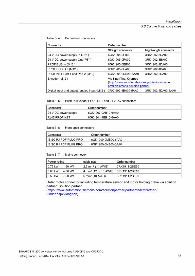
Table 3- 4 Control unit connectors
Connector Order number Straight connector Right-angle connector 24 V DC power supply In (7/8" ) 6GK1905-0FB00 3RK1902-3DA00 24 V DC power supply Out (7/8" ) 6GK1905-0FA00 3RK1902-3BA00 PROFIBUS In (M12 ) 6GK1905-0EB00 3RK1902-1DA00 PROFIBUS Out (M12 ) 6GK1905-0EA00 3RK1902-1BA00 PROFINET Port 1 and Port 2 (M12) 6GK1901-0DB20-6AA0 3RK1902-2DA00 Encoder (M12 ) Via KnorrTec: Knorrtec
(http://www.knorrtec.de/index.php/en/company-profile/siemens-solution-partner)
Digital input and output, analog input (M12 ) 3RK1902-4BA00-5AA0 3RK1902-4DA00-5AA0
Table 3- 5 Push-Pull variant PROFINET and 24 V DC connectors
Connector Order number 24 V DC power supply 6GK1907-0AB10-6AA0 RJ45 PROFINET 6GK1901-1BB10-6AA0
Table 3- 6 Fibre optic connectors
Connector Order number IE SC RJ POF PLUG PRO 6GK1900-0MB00-6AA0 IE SC RJ PCF PLUG PRO 6GK1900-0NB00-6AA0
Table 3- 7 Mains connector
Power rating cable size Order number 0.75 kW … 1.50 kW 2.5 mm2 (14 AWG) 3RK1911-2BE50 3.00 kW … 4.00 kW 4 mm2 (12 or 10 AWG) 3RK1911-2BE10 5.50 kW … 7.50 kW 6 mm2 (10 AWG) 3RK1911-2BE30
Order motor connector including temperature sensor and motor holding brake via solution partner: Solution partner (https://www.automation.siemens.com/solutionpartner/partnerfinder/Partner-Finder.aspx?lang=en)
Installation 3.6 Connections and cables
SINAMICS G120D converter with control units CU240D-2 and CU250D-2 36 Getting Started, 04/12014, FW V4.7, A5E34262374B AA
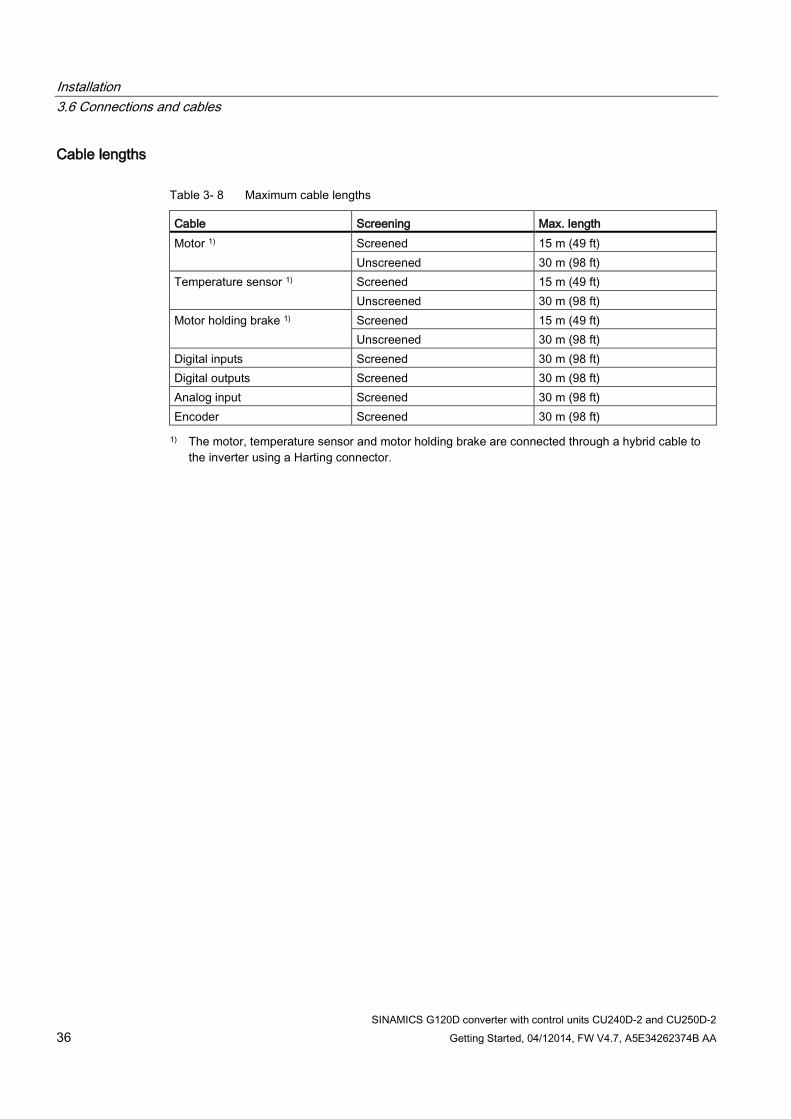
Cable lengths
Table 3- 8 Maximum cable lengths
Cable Screening Max. length Motor 1) Screened 15 m (49 ft)
Unscreened 30 m (98 ft) Temperature sensor 1) Screened 15 m (49 ft)
Unscreened 30 m (98 ft) Motor holding brake 1) Screened 15 m (49 ft)
Unscreened 30 m (98 ft) Digital inputs Screened 30 m (98 ft) Digital outputs Screened 30 m (98 ft) Analog input Screened 30 m (98 ft) Encoder Screened 30 m (98 ft) 1) The motor, temperature sensor and motor holding brake are connected through a hybrid cable to
the inverter using a Harting connector.
Installation 3.6 Connections and cables
SINAMICS G120D converter with control units CU240D-2 and CU250D-2 Getting Started, 04/12014, FW V4.7, A5E34262374B AA 37
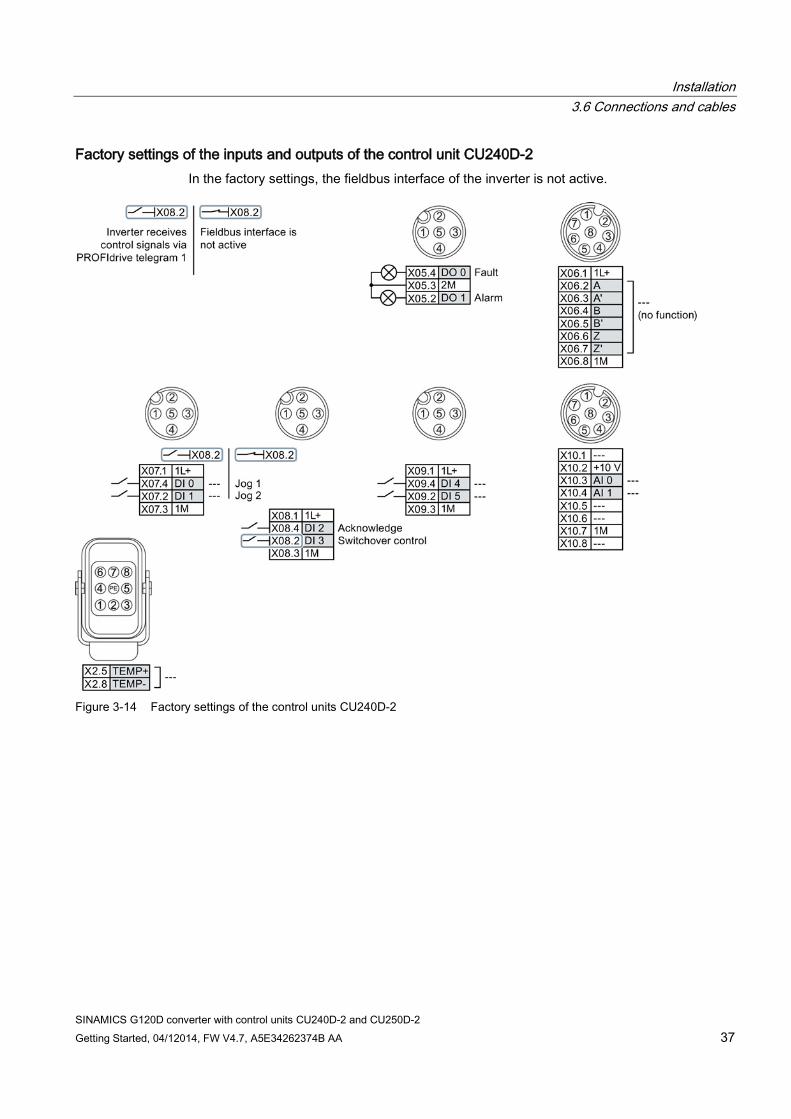
Factory settings of the inputs and outputs of the control unit CU240D-2 In the factory settings, the fieldbus interface of the inverter is not active.
Figure 3-14 Factory settings of the control units CU240D-2

Installation 3.6 Connections and cables
SINAMICS G120D converter with control units CU240D-2 and CU250D-2 38 Getting Started, 04/12014, FW V4.7, A5E34262374B AA
Factory settings of the inputs and outputs of the CU250D-2 control unit In the factory settings, the fieldbus interface of the inverter is not active.
Figure 3-15 Factory settings of the CU250D-2 control units
Changing the function of terminals The function of every color-coded terminal can be set.
In order that you do not have to successively change terminal for terminal, several terminals can be jointly set using default settings.
The factory setting of the terminals described above corresponds to the default setting 7 (switchover between fieldbus and a jog using DI 3).
See also: Default settings of inputs and outputs (Page 39).

Installation 3.7 Default settings of inputs and outputs
SINAMICS G120D converter with control units CU240D-2 and CU250D-2 Getting Started, 04/12014, FW V4.7, A5E34262374B AA 39
3.7 Default settings of inputs and outputs
Default settings of inputs and outputs (CU240D-2)
Default setting 1: Two fixed speeds Default setting 2: Two fixed speeds with safety function
Default setting 3: Four fixed speeds
Fieldbus interface is not active.
DI 4 and DI 5 = high: The inverter adds both fixed speeds.
Fieldbus interface is not active.
Fieldbus interface is not active.
Multiple DIs = high: The inverter adds the corresponding fixed speeds.
Default setting 4: PROFIBUS or
PROFINET Default setting 5: PROFIBUS or PROFINET with safety function
Default setting 6: PROFIBUS or PROFINET with two safety functions
PROFIdrive telegram 352
PROFIdrive telegram 352
PROFIdrive telegram 1 Only with Control Units CU240D-2 DP-F and CU240D-2 PN-F.
Default setting 7: Switch over between fieldbus and jogging using DI 3 Factory setting
Default setting 8: Motorized potentiometer (MOP) with safety
function PROFIdrive telegram 1
Fieldbus interface is not active.
Fieldbus interface is not active.

Installation 3.7 Default settings of inputs and outputs
SINAMICS G120D converter with control units CU240D-2 and CU250D-2 40 Getting Started, 04/12014, FW V4.7, A5E34262374B AA
Default setting 9: Motorized
potentiometer (MOP) Default setting 12: Two-wire control
with method 1 Default setting 13: Setpoint via analog
input with safety function Fieldbus interface is not active.
Fieldbus interface is not active.
Fieldbus interface is not active.
Default setting 14: Switch over between fieldbus and motorized potentiometer (MOP) using DI 3
Default setting 24: Communication via fieldbus; transfer of all DIs and DOs to
fieldbus PROFIdrive telegram 20
Fieldbus interface is not active.
PROFIdrive telegram 352 + PZD7
Default setting 25: Communication via fieldbus with safety function; transfer of the DI 0 to DI 3 and all DOs to fieldbus
PROFIdrive telegram 352 + PZD7
Default settings of inputs and outputs (CU250D-2)
Default setting 26: Basic positioner via inputs and outputs; factory settings
Default setting 27: Basic positioner via fieldbus
The fieldbus interface is not active.
PROFIdrive telegram 111

Installation 3.8 Settings PROFIBUS DP address with DIP switches
SINAMICS G120D converter with control units CU240D-2 and CU250D-2 Getting Started, 04/12014, FW V4.7, A5E34262374B AA 41
3.8 Settings PROFIBUS DP address with DIP switches
Setting the PROFIBUS DP address Prior to using the PROFIBUS DP interface, the address of the node (Inverter) must be set using the seven PROFIBUS DP address DIP switches on the Control Unit.
The PROFIBUS DP address can be set between 1 and 126.
Note
The address is taken from P0918 if all PROFIBUS DP address DIP switches are in the OFF position, otherwise the DIP switch setting is valid.
NOTICE
External 24 V power supply must be disconnected
The external 24 V power supply must be switched off before the DIP switch settings are changed. DIP switch setting changes do not take effect until the Control Unit has been powered-up again.
Setting the PROFIBUS DP address via DIP switches The PROFIBUS DP address can be set via DIP switch, as shown in the table below.
Table 3- 9 Example address for the PROFIBUS DP interface
DIP switch 1 2 3 4 5 6 7 Add to address 1 2 4 8 16 32 64 Example 1: Address = 3 = 1 + 2
Example 2: Address = 88 = 8 + 16 + 64

Installation 3.9 Connecting the PROFINET interface
SINAMICS G120D converter with control units CU240D-2 and CU250D-2 42 Getting Started, 04/12014, FW V4.7, A5E34262374B AA
3.9 Connecting the PROFINET interface
Industrial Ethernet Cables and cable length Listed in the table below are the recommended Ethernet cables.
Table 3- 10 Recommended PROFINET cables
Max. Cable Length Order Number Industrial Ethernet FC TP Standard Cable GP 2 x 2 100 m (328 ft) 6XV1840-2AH10 Industrial Ethernet FC TP Flexible Cable GP 2 x 2 85 m (278 ft) 6XV1870–2B Industrial Ethernet FC Trailing Cable GP 2 x 2 85 m (278 ft) 6XV1870–2D Industrial Ethernet FC Trailing Cable 2 x 2 85 m (278 ft) 6XV1840–3AH10 Industrial Ethernet FC Marine Cable 2 x 2 85 m (278 ft) 6XV1840–4AH10
Cable screening The screen of the PROFINET cable must be connected with the protective earth. The solid copper core must not be scored when the insulation is removed from the core ends.
3.10 Grounding converter and motor
Grounding the converter ● Ground the converter via the PE connection in the mains supply connector.
● Ground the connectors as shown in the diagram below.
Figure 3-16 Grounding the line supply and motor connectors

Installation 3.10 Grounding converter and motor
SINAMICS G120D converter with control units CU240D-2 and CU250D-2 Getting Started, 04/12014, FW V4.7, A5E34262374B AA 43
• Connect the PE terminal on the left-hand side
of the converter to the metal frame it is mounted on.
• Recommended cable cross section: 10 mm² • Use a short wire connection preferably. • Clean the connection to the steel construction
from paint or dirt. • Use a ring clamp to ensure a good physical
connection which is resistant to accidental disconnection.
Grounding the motor ● Ground the motor via the PE connection in the motor connector.
● Ground the connector as shown in the diagram above (grounding the converter). Although the line and motor connectors are of a different type, the principle of grounding them is the same.
● If possible, ground the motor housing.
EMC cable glands Where cable glands are used within the installation of the system, it is recommended that EMC glands are used.
The cable gland provides protection to the IP68 standard when fitted correctly.
Figure 3-17 Example of a Blueglobe EMC cable gland
Table 3- 11 Brass-nickel plated EMC cable gland with metric thread as per EN50262.
Connection thread/length Clamping range without inlet max/min [mm]
Clamping range max/min [mm]
Spanner width SW * E
Order No.
A D [mm] C [mm]
M16 x 1.5 6.0 29 11 … 7 9 … 7 20 x 22.2 bg216mstri M20 x 1.5 6.5 29 14 … 9 12 … 7 24 x 26.5 bg220mstri M25 x 1.5 7.5 29 20 … 13 16… 10 30 x 33 bg255mstri M32 x 1.5 8.0 32 25 … 20 20 … 13 36 x 39.5 bg232mstri

Installation 3.11 Connections and interference suppression
SINAMICS G120D converter with control units CU240D-2 and CU250D-2 44 Getting Started, 04/12014, FW V4.7, A5E34262374B AA
3.11 Connections and interference suppression All connections should be made so that they are permanent. Screwed connections on painted or anodized metal components must be made either by means of special contact washers, which penetrate the isolating surface and establish a metallically conductive contact, or by removing the isolating surface on the contact points.
Contactor coils, relays, solenoid valves, and motor holding brakes must have interference suppressors to reduce high-frequency radiation when the contacts are opened (RC elements or varistors for AC currentoperated coils, and freewheeling diodes for DC current-operated coils). The interference suppressors must be connected directly on each coil.
3.12 Equipotential bonding
Grounding and high-frequency equipotential bonding measures Equipotential bonding within the drive system has to be established by connecting all electrical and mechanical drive components (transformer, motor and driven machine) to the grounding system. These connections are established by means of standard heavy-power PE cables, which do not need to have any special high-frequency properties.
In addition to these connections, the inverter (as the source of the high-frequency interference) and the motor must be interconnected with respect to the high-frequency point of view:
1. Use a shielded motor cable.
2. Connect the cable shield both to the motor connector on the inverter and to the motor terminal box.
3. Use a short grounding connection from the PE terminal on the inverter to the metal frame.
The following figure illustrates all grounding and high-frequency equipotential bonding measures using an example.

Installation 3.12 Equipotential bonding
SINAMICS G120D converter with control units CU240D-2 and CU250D-2 Getting Started, 04/12014, FW V4.7, A5E34262374B AA 45
① Transformer ② Second level distribution with PE equipotential bonding ③ Metal frame ④ Short connection from the PE terminal to the metal frame. ⑤ Electrical connection of motor cable shield and connector body. ⑥ Electrical connection of motor cable shield and motor terminal box via electrically conductive PG
gland. ⑦ Driven machine ⑧ Conventional grounding system.
• Standard, heavy-power PE conductors without special high-frequency properties. • Ensures low frequency equipotential bonding as well as protection against injury.
⑨ Foundation ground
Figure 3-18 Grounding and high-frequency equipotential bonding measures in the drive system and in the plant
For general rules for EMC compliant installation see also: http://support.automation.siemens.com/WW/view/de/60612658 (http://support.automation.siemens.com/WW/view/en/60612658)


SINAMICS G120D converter with control units CU240D-2 and CU250D-2 Getting Started, 04/12014, FW V4.7, A5E34262374B AA 47
Commissioning 4 4.1 Default settings for the SINAMICS G120D
Factory default settings The inverter system is shipped from the factory as a Control Unit and a Power Module. Without any parameterization or after a factory reset, the inverter can be operated without additional parameterization if the inverter default settings (which depend on the inverter type and size) match the following data of a 4-pole motor: Default line supply frequency 50 Hz Rated motor voltage P0304 Rated motor current P0305 Rated motor power P0307 Rated motor frequency P0310 Rated motor speed P0311 (A Siemens standard motor is recommended.) Further, the following conditions must be fulfilled: Control (ON/OFF command) using digital inputs See pre-assigned inputs below. Asyncronous motor P0300 = 1 Self-cooled motor P0335 = 0 Motor overload factor P0640 = 150 % Min. frequency P1080 = 0 Hz Max. frequency P1082 = 50 Hz Ramp-up time P1120 = 10 s Ramp-down time P1121 = 10 s Linear V/f characteristic P1300 = 0
The Control Unit is intended to be control and operate the inverter utilizing the PROFIBUS or PROFINET interface. The PROFIBUS or PROFINET interface may be used to further configure and control the inverter as required.
Commissioning 4.2 Commissioning with the IOP
SINAMICS G120D converter with control units CU240D-2 and CU250D-2 48 Getting Started, 04/12014, FW V4.7, A5E34262374B AA
4.2 Commissioning with the IOP
Commission the Inverter The Intelligent Operator Panel (IOP) has been designed to enhance the interface and communications capabilities of the SINAMICS Inverters.
The IOP is connected to the Inverter using an Optical RS232 cable. It will automatically recognise the specific Control Unit to which it is connected, and displays only the parameters and funtionality of the connected Control Unit.
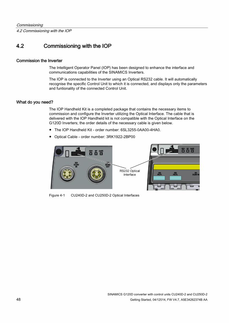
What do you need? The IOP Handheld Kit is a completed package that contains the necessary items to commission and configure the Inverter utilizing the Optical Interface. The cable that is delivered with the IOP Handheld kit is not compatible with the Optical Interface on the G120D Inverters; the order details of the necessary cable is given below.
● The IOP Handheld Kit - order number: 6SL3255-0AA00-4HA0.
● Optical Cable - order number: 3RK1922-2BP00
Figure 4-1 CU240D-2 and CU250D-2 Optical Interfaces

Commissioning 4.2 Commissioning with the IOP
SINAMICS G120D converter with control units CU240D-2 and CU250D-2 Getting Started, 04/12014, FW V4.7, A5E34262374B AA 49
Basic commissioning wizard The Basic Commissioning wizard detailed below is for Control Units with version 4.4 software or higher.
Procedure
For performing the basic commissioning of the converter with the IOP operator panel, proceed the following steps: 1. Select "Basic Commissioning..." from the Wizards
menu.
2. Select "Yes" or "No" to a factory reset. The factory reset is performed prior to saving all the parameter changes that have been made during the basic commissioning process.
3. Select the Control Mode for the attached motor.
4. Select the correct Motor Data for your Inverter and attached motor. This data is used to calulate the correct speed and displayed values for the application.
5. Select the correct frequency for your Inverter and attached motor. The use of the 87 Hz characteristic allows the motor to operate at 1.73 times of its normal speed.

Commissioning 4.2 Commissioning with the IOP
SINAMICS G120D converter with control units CU240D-2 and CU250D-2 50 Getting Started, 04/12014, FW V4.7, A5E34262374B AA
6. At this stage the wizard will begin to ask for the data relating specifically to the attached motor. The data is obtained from the motor rating plate.
7. The Motor Data screen indicates the frequency characteristic of the attached motor.
8. Input the correct Motor Voltage from the motor rating plate.
9. Input the correct Motor Current from the motor rating plate.
10. Input the correct Power Rating from the motor rating plate.
11. Input the correct Motor Speed from the motor rating plate. This value is given in RPM.

Commissioning 4.2 Commissioning with the IOP
SINAMICS G120D converter with control units CU240D-2 and CU250D-2 Getting Started, 04/12014, FW V4.7, A5E34262374B AA 51
12. Select to run or disable Motor Data Identification function. This function, if active, will not start until the first run command is given to the Inverter.
13. Select either zero pulse on no zero pulse for the attached encoder. If no encoder is fitted to the motor, the option will not be displayed.
14. Enter the correct pulses per revolution for the encoder. This information is normally printed on the casing of the encoder.
15. Select the macro that is suitable for your application. Once selected all inputs, outputs, command sources and setpoints will be automatically configured by the software. For further information see the section that details the precise settings for each macro. Please see installation section of this manual.
16. Set the Minimum Speed at which the attached motor should run.
17. Set the Ramp Up time in seconds. This is the time the Inverter/motor system will take from being given the run command, to reaching the selected motor speed.

Commissioning 4.2 Commissioning with the IOP
SINAMICS G120D converter with control units CU240D-2 and CU250D-2 52 Getting Started, 04/12014, FW V4.7, A5E34262374B AA
18. Set the Ramp Down time in seconds. This is the time the Inverter/motor system will take from being given the OFF1 command, for the motor to reach a standstill.
19. A summary of all the settings is display. If the settings are correct, select Continue.
20. The final screen gives two options: • Save settings • Cancel Wizard If save is selected, a factory reset will be performed then the settings are saved to the Inverter memory. The location of safe data is assigned using the "Parameter saving mode" function in "Parameter settings" in "Menu".
The basic commissioning of your converter is finished.

Commissioning 4.3 Commissioning the application
SINAMICS G120D converter with control units CU240D-2 and CU250D-2 Getting Started, 04/12014, FW V4.7, A5E34262374B AA 53
4.3 Commissioning the application
Commissioning the applications The Intelligent Operator Panel (IOP) allows the commissioning of a variety of applications utilizing a step-by-step wizard that presents the user with the questions relevant to the application being commissioned. When used in conjunction with the various wiring diagrams contained within the IOP Operating Instructions, the application can be quickly and easily commissioned.
Figure 4-2 Example of IOP Wizards and Inverter wiring diagrams

Commissioning 4.4 Reset Parameters to Factory Settings
SINAMICS G120D converter with control units CU240D-2 and CU250D-2 54 Getting Started, 04/12014, FW V4.7, A5E34262374B AA
4.4 Reset Parameters to Factory Settings
Overview With a factory reset via P0970 the initial state of the all the inverter parameters can be re-established.
The factory setting values are designated as "Factory setting" in the Parameter Manual.
For further information, refer to the section "Factory Settings of the Control Unit" in this manual.
Note
When resetting the parameters to the factory setting, the communications memory is re-initialized. This means that communications are interrupted for the time it takes to perform the reset.
WARNING
Parameter reset in case of CUs with fail-safe functions
Parameters that don't relate to fail-safe functions are reset with P0970 = 1.
To reset parameters that relate to fail-safe functions an additional parameter reset with P0970 = 5 must be performed. This parameter reset is password protected.
In case of a parameter reset with P0970 = 5 an acceptance test necessary.
SINAMICS G120D converter with control units CU240D-2 and CU250D-2 Getting Started, 04/12014, FW V4.7, A5E34262374B AA 55
Troubleshooting 5 5.1 List of alarms and faults
Axxxxx Alarm
Fyyyyy: Fault
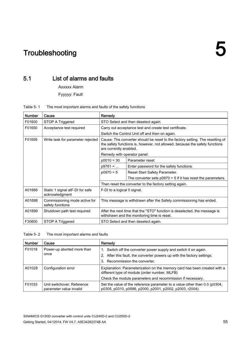
Table 5- 1 The most important alarms and faults of the safety functions
Number Cause Remedy F01600 STOP A Triggered STO Select and then deselect again. F01650 Acceptance test required Carry out acceptance test and create test certificate.
Switch the Control Unit off and then on again. F01659 Write task for parameter rejected Cause: The converter should be reset to the factory setting. The resetting of
the safety functions is, however, not allowed, because the safety functions are currently enabled. Remedy with operator panel: p0010 = 30 Parameter reset p9761 = … Enter password for the safety functions. p0970 = 5 Reset Start Safety Parameter.
The converter sets p0970 = 5 if it has reset the parameters. Then reset the converter to the factory setting again.
A01666 Static 1 signal atF-DI for safe acknowledgment
F-DI to a logical 0 signal.
A01698 Commissioning mode active for safety functions
This message is withdrawn after the Safety commissioning has ended.
A01699 Shutdown path test required After the next time that the "STO" function is deselected, the message is withdrawn and the monitoring time is reset.
F30600 STOP A Triggered STO Select and then deselect again.
Table 5- 2 The most important alarms and faults
Number Cause Remedy F01018 Power-up aborted more than
once 1. Switch off the converter power supply and switch it on again. 2. After this fault, the converter powers up with the factory settings. 3. Recommission the converter.
A01028 Configuration error Explanation: Parameterization on the memory card has been created with a different type of module (order number, MLFB) Check the module parameters and recommission if necessary.
F01033 Unit switchover: Reference parameter value invalid
Set the value of the reference parameter to a value other than 0.0 (p0304, p0305, p0310, p0596, p2000, p2001, p2002, p2003, r2004).

Troubleshooting 5.1 List of alarms and faults
SINAMICS G120D converter with control units CU240D-2 and CU250D-2 56 Getting Started, 04/12014, FW V4.7, A5E34262374B AA
Number Cause Remedy F01034 Unit switchover: Calculation of
the parameter values after reference value change unsuccessful
Select the value of the reference parameter so that the parameters involved can be calculated in the per unit notation (p0304, p0305, p0310, p0596, p2000, p2001, p2002, p2003, r2004).
F01122 Frequency at the probe input too high
Reduce the frequency of the pulses at the probe input.
A01590 Motor maintenance interval lapsed
Carry out the maintenance.
A01900 PROFIBUS: Configuration telegram faulty
Explanation: A PROFIBUS master is attempting to establish a connection with a faulty configuration telegram. Check the bus configuration on the master and slave side.
A01910 F01910
Fieldbus SS setpoint timeout The alarm is generated when p2040 ≠ 0 ms and one of the following causes is present: • The bus connection is interrupted • The MODBUS master is switched off • Communications error (CRC, parity bit, logical error) An excessively low value for the fieldbus monitoring time (p2040)
A01920 PROFIBUS: Cyclic connection interrupt
Explanation: The cyclic connection to PROFIBUS master is interrupted. Establish the PROFIBUS connection and activate the PROFIBUS master with cyclic operation.
F03505 Analog input, wire break Check the connection to the signal source for interrupts. Check the level of the signal supplied. The input current measured by the analog input can be read out in r0752.
A03520 Temperature sensor fault Check that the sensor is connected correctly. A05000 A05001 A05002 A05004 A05006
Power Module overtemperature Check the following: - Is the ambient temperature within the defined limit values? - Are the load conditions and duty cycle configured accordingly? - Has the cooling failed?
F06310 Supply voltage (p0210) incorrectly parameterized
Check the parameterized supply voltage and if required change (p0210). Check the line voltage.
F07011 Motor overtemperature Reduce the motor load. Check ambient temperature. Check sensor's wiring and connection.
A07012 I2t Motor Module overtemperature
Check and if necessary reduce the motor load. Check the motor's ambient temperature. Check thermal time constant p0611. Check overtemperature fault threshold p0605.
A07015 Motor temperature sensor alarm Check that the sensor is connected correctly. Check the parameter assignment (p0601).
F07016 Motor temperature sensor fault Make sure that the sensor is connected correctly. Check the parameterization (p0601).
F07086 F07088
Unit switchover: Parameter limit violation
Check the adapted parameter values and if required correct.

Troubleshooting 5.1 List of alarms and faults
SINAMICS G120D converter with control units CU240D-2 and CU250D-2 Getting Started, 04/12014, FW V4.7, A5E34262374B AA 57
Number Cause Remedy F07320 Automatic restart aborted Increase the number of restart attempts (p1211). The current number of
start attempts is shown in r1214. Increase the wait time in p1212 and/or monitoring time in p1213. Create ON command (p0840). Increase the monitoring time of the power unit or switch off (p0857). Reduce the wait time for resetting the fault counter p1213[1] so that fewer faults are registered in the time interval.
A07321 Automatic restart active Explanation: The automatic restart (AR) is active. During voltage recovery and/or when remedying the causes of pending faults, the drive is automatically switched back on.
F07330 Search current measured too low
Increase search current (P1202), check motor connection.
A07400 VDC_max controller active If the controller is not to intervene: • Increase the ramp-down times. • Deactivate the VDC_max controller (p1240 = 0 for vector control, p1280 = 0
for V/f control).
A07409 V/f control current limiting controller active
The alarm automatically disappears after one of the following measures: • Increase the current limit (p0640). • Reduce load. • Increase the ramp-up time to the speed setpoint.
F07426 Technology controller actual value limited
• Adapt the limits to the signal level (p2267, p2268). • Check the actual value scaling (p2264).
F07801 Motor overcurrent Check current limits (p0640). U/f control: Check the current limiting controller (p1340 … p1346). Increase acceleration ramp (p1120) or reduce load. Check motor and motor cables for short circuit and ground fault. Check motor for star-delta connection and rating plate parameterization. Check power unit / motor combination. Select flying restart function (p1200) if switched to rotating motor.
A07805 Drive: Power unit overload I2t • Reduce the continuous load. • Adapt the load cycle. • Check the assignment of rated currents of the motor and power unit.
F07807 Short circuit detected • Check the converter connection on the motor side for any phase-phase short-circuit.
• Rule out that line and motor cables have been interchanged.
A07850 External alarm 1 The signal for "external alarm 1" has been triggered. Parameter p2112 defines the signal source of the external alarm. Remedy: Rectify the cause of this alarm.
F07860 External fault 1 Remove the external causes for this fault. F07900 Motor blocked • Make sure that the motor can rotate freely.
• Check the torque limit: r1538 for a positive direction of rotation; r1539 for a negative direction of rotation.
Troubleshooting 5.1 List of alarms and faults
SINAMICS G120D converter with control units CU240D-2 and CU250D-2 58 Getting Started, 04/12014, FW V4.7, A5E34262374B AA
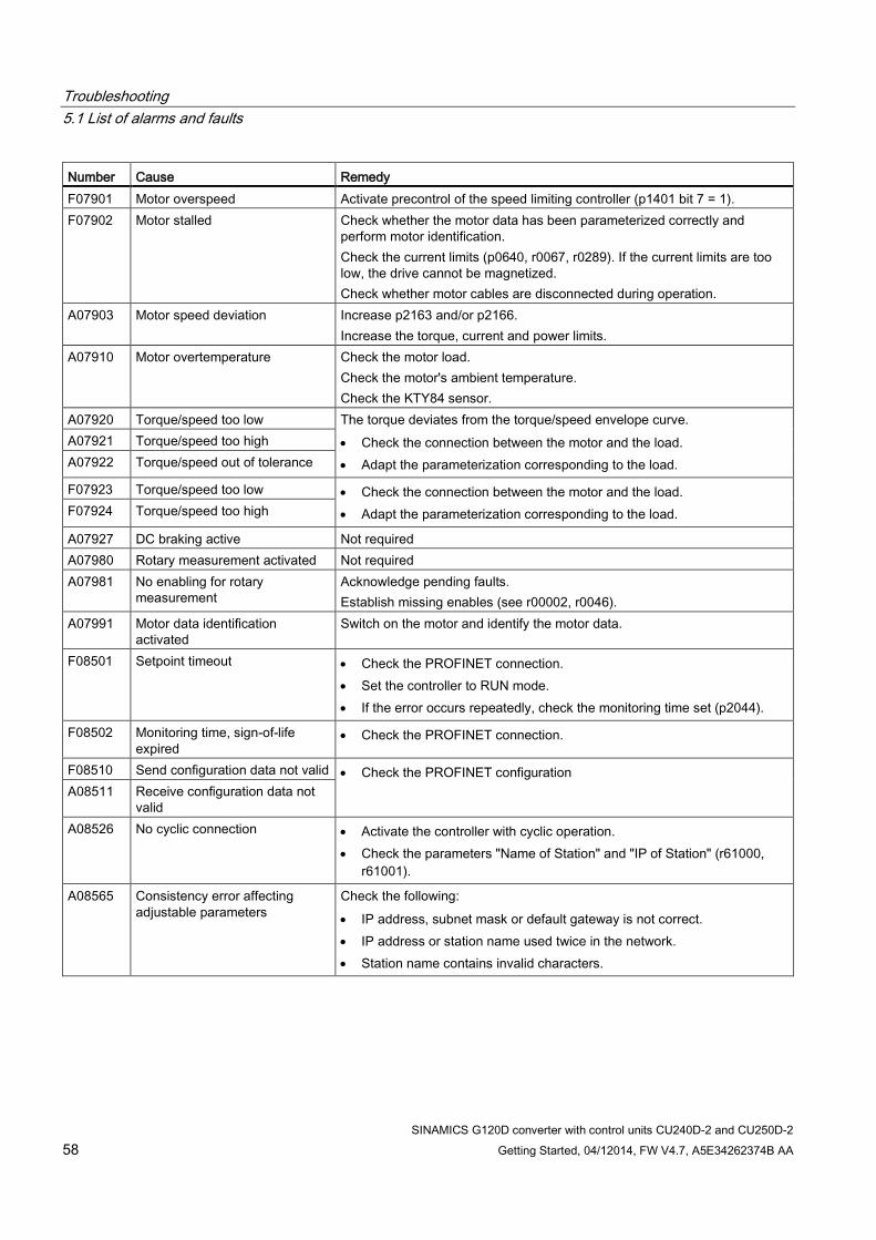
Number Cause Remedy F07901 Motor overspeed Activate precontrol of the speed limiting controller (p1401 bit 7 = 1). F07902 Motor stalled Check whether the motor data has been parameterized correctly and
perform motor identification. Check the current limits (p0640, r0067, r0289). If the current limits are too low, the drive cannot be magnetized. Check whether motor cables are disconnected during operation.
A07903 Motor speed deviation Increase p2163 and/or p2166. Increase the torque, current and power limits.
A07910 Motor overtemperature Check the motor load. Check the motor's ambient temperature. Check the KTY84 sensor.
A07920 Torque/speed too low The torque deviates from the torque/speed envelope curve. • Check the connection between the motor and the load. • Adapt the parameterization corresponding to the load.
A07921 Torque/speed too high A07922 Torque/speed out of tolerance
F07923 Torque/speed too low • Check the connection between the motor and the load. • Adapt the parameterization corresponding to the load. F07924 Torque/speed too high
A07927 DC braking active Not required A07980 Rotary measurement activated Not required A07981 No enabling for rotary
measurement Acknowledge pending faults. Establish missing enables (see r00002, r0046).
A07991 Motor data identification activated
Switch on the motor and identify the motor data.
F08501 Setpoint timeout • Check the PROFINET connection. • Set the controller to RUN mode. • If the error occurs repeatedly, check the monitoring time set (p2044).
F08502 Monitoring time, sign-of-life expired
• Check the PROFINET connection.
F08510 Send configuration data not valid • Check the PROFINET configuration A08511 Receive configuration data not
valid A08526 No cyclic connection • Activate the controller with cyclic operation.
• Check the parameters "Name of Station" and "IP of Station" (r61000, r61001).
A08565 Consistency error affecting adjustable parameters
Check the following: • IP address, subnet mask or default gateway is not correct. • IP address or station name used twice in the network. • Station name contains invalid characters.

Troubleshooting 5.1 List of alarms and faults
SINAMICS G120D converter with control units CU240D-2 and CU250D-2 Getting Started, 04/12014, FW V4.7, A5E34262374B AA 59
Number Cause Remedy F08700 Communications error A CAN communications error has occurred. Check the following:
• Bus cable • Baud rate (p8622) • Bit timing (p8623) • Master Start the CAN controller manually with p8608 = 1 after the cause of the fault has been resolved!
F13100 Know-how protection: Copy protection error
The know-how protection and the copy protection for the memory card are active. An error occurred during checking of the memory card. • Insert a suitable memory card and switch the converter supply voltage
temporarily off and then on again (POWER ON). • Deactivate the copy protection (p7765).
F13101 Know-how protection: Copy protection cannot be activated
Insert a valid memory card.
F30001 Overcurrent Check the following: • Motor data, if required, carry out commissioning • Motor's connection method (Υ / Δ) • U/f operation: Assignment of rated currents of motor and Power Module • Line quality • Make sure that the line commutating reactor is connected properly • Power cable connections • Power cables for short-circuit or ground fault • Power cable length • Line phases If this doesn't help: • U/f operation: Increase the acceleration ramp • Reduce the load • Replace the power unit
F30002 DC-link voltage overvoltage Increase the ramp-down time (p1121). Set the rounding times (p1130, p1136). Activate the DC link voltage controller (p1240, p1280). Check the line voltage (p0210). Check the line phases.
F30003 DC-link voltage undervoltage Check the line voltage (p0210). F30004 Converter overtemperature Check whether the converter fan is running.
Check whether the ambient temperature is in the permissible range. Check whether the motor is overloaded. Reduce the pulse frequency.
F30005 I2t converter overload Check the rated currents of the motor and Power Module. Reduce current limit p0640. When operating with U/f characteristic: Reduce p1341.
Troubleshooting 5.1 List of alarms and faults
SINAMICS G120D converter with control units CU240D-2 and CU250D-2 60 Getting Started, 04/12014, FW V4.7, A5E34262374B AA
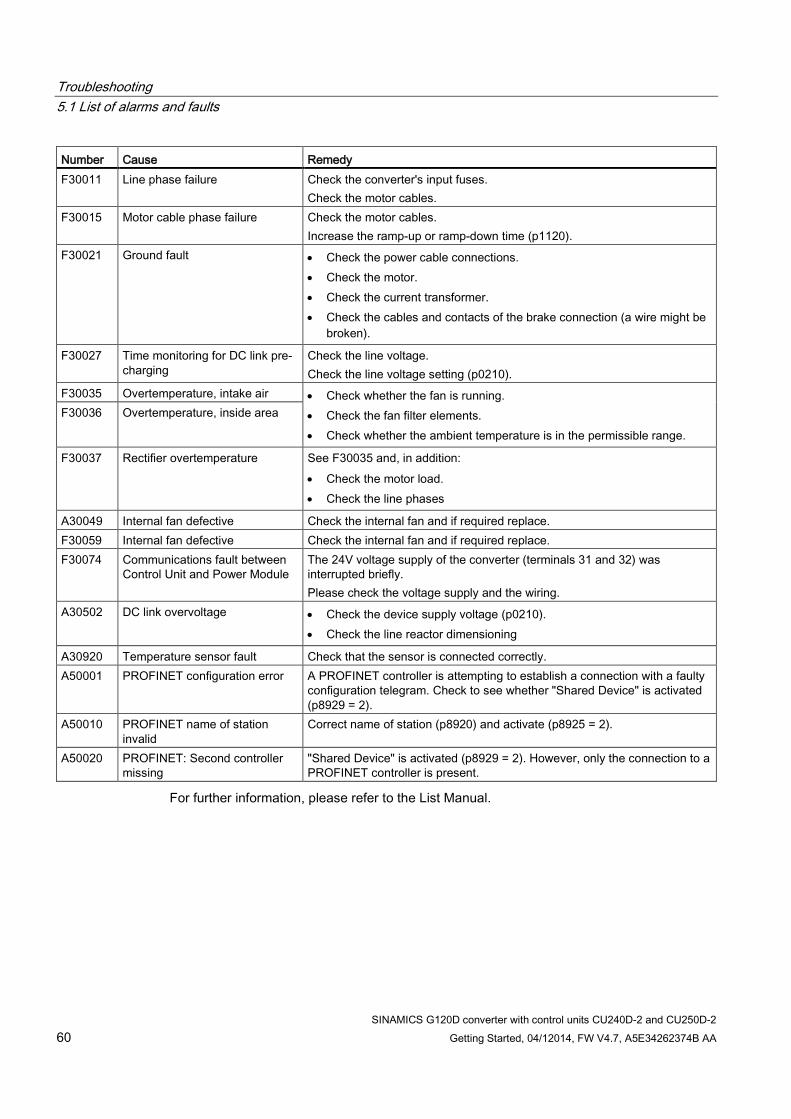
Number Cause Remedy F30011 Line phase failure Check the converter's input fuses.
Check the motor cables. F30015 Motor cable phase failure Check the motor cables.
Increase the ramp-up or ramp-down time (p1120). F30021 Ground fault • Check the power cable connections.
• Check the motor. • Check the current transformer. • Check the cables and contacts of the brake connection (a wire might be
broken).
F30027 Time monitoring for DC link pre-charging
Check the line voltage. Check the line voltage setting (p0210).
F30035 Overtemperature, intake air • Check whether the fan is running. • Check the fan filter elements. • Check whether the ambient temperature is in the permissible range.
F30036 Overtemperature, inside area
F30037 Rectifier overtemperature See F30035 and, in addition: • Check the motor load. • Check the line phases
A30049 Internal fan defective Check the internal fan and if required replace. F30059 Internal fan defective Check the internal fan and if required replace. F30074 Communications fault between
Control Unit and Power Module The 24V voltage supply of the converter (terminals 31 and 32) was interrupted briefly. Please check the voltage supply and the wiring.
A30502 DC link overvoltage • Check the device supply voltage (p0210). • Check the line reactor dimensioning
A30920 Temperature sensor fault Check that the sensor is connected correctly. A50001 PROFINET configuration error A PROFINET controller is attempting to establish a connection with a faulty
configuration telegram. Check to see whether "Shared Device" is activated (p8929 = 2).
A50010 PROFINET name of station invalid
Correct name of station (p8920) and activate (p8925 = 2).
A50020 PROFINET: Second controller missing
"Shared Device" is activated (p8929 = 2). However, only the connection to a PROFINET controller is present.
For further information, please refer to the List Manual.
Troubleshooting 5.2 Status LED overview
SINAMICS G120D converter with control units CU240D-2 and CU250D-2 Getting Started, 04/12014, FW V4.7, A5E34262374B AA 61
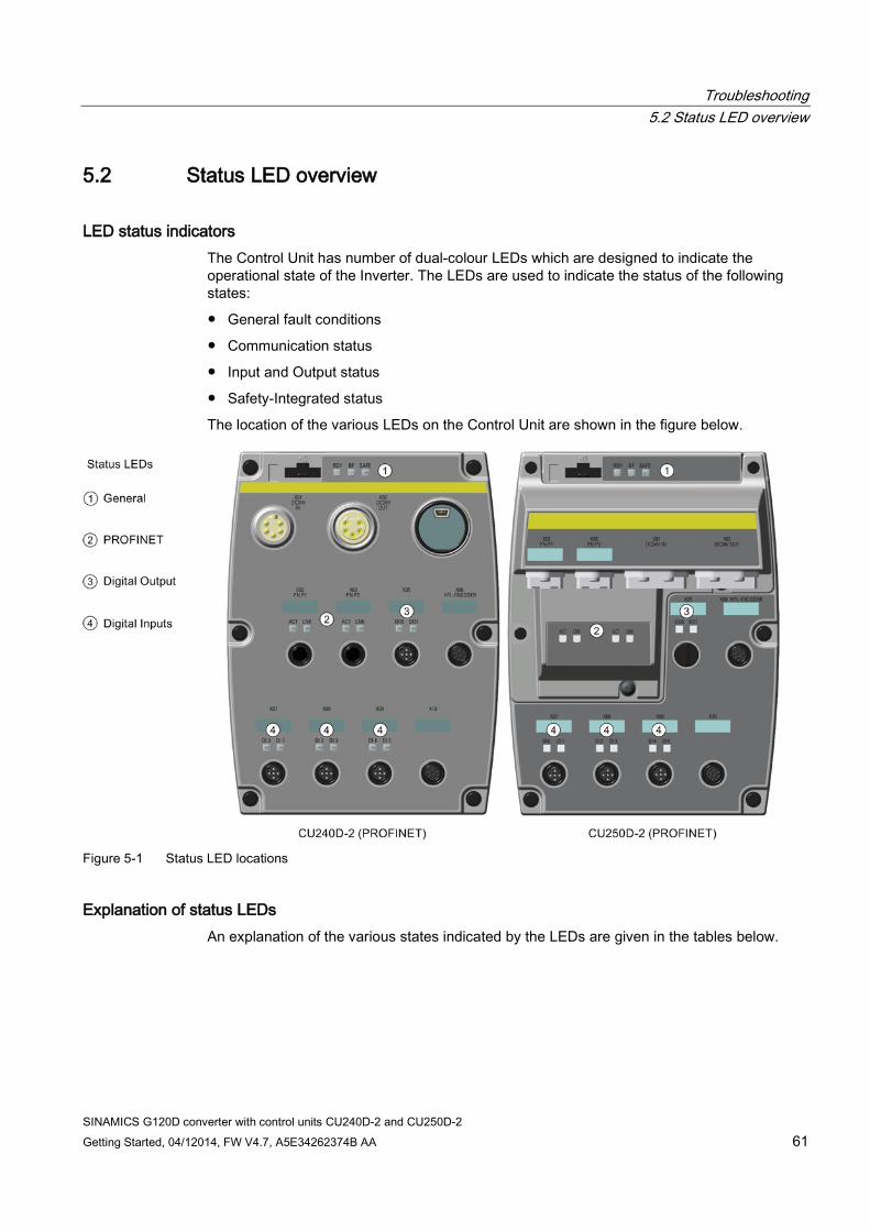
5.2 Status LED overview
LED status indicators The Control Unit has number of dual-colour LEDs which are designed to indicate the operational state of the Inverter. The LEDs are used to indicate the status of the following states:
● General fault conditions
● Communication status
● Input and Output status
● Safety-Integrated status
The location of the various LEDs on the Control Unit are shown in the figure below.
Figure 5-1 Status LED locations
Explanation of status LEDs An explanation of the various states indicated by the LEDs are given in the tables below.

Troubleshooting 5.2 Status LED overview
SINAMICS G120D converter with control units CU240D-2 and CU250D-2 62 Getting Started, 04/12014, FW V4.7, A5E34262374B AA
Table 5- 3 Description of general status LEDS
RDY BF Description of function GREEN - On - Ready for operation (no active fault) GREEN - flashing slowly - Commissioning or reset of factory settings RED - on Off Firmware update in progress RED - flashing slowly RED - flashing slowly Firmware updated is complete - power ON reset required RED - flashing quickly - General fault condition RED - flashing quickly RED - On Fault occurred during firmware update RED - flashing quickly RED - flashing quickly Incompatible firmware or incorrect memory card
Table 5- 4 Description of PROFIBUS communications LED
BF Description of function Off Cyclic data exchange (or PROFIBUS not in use - p2030 = 0) RED - flashing slowly Bus fault - configuration fault RED - flashing quickly Bus fault:
- no data exchange - baud rate search - cannot detect the correct baud rate - no connection - the connection between the Inverter and PLC has been lost
Table 5- 5 Description of SAFE LED
SAFE Description of function YELLOW - On One or more safety functions are enabled - but not active YELLOW - flashing slowly One or more safety functions are active - no safety function faults have occurred. YELLOW - flashing quickly The Inverter has detected a safety function fault and initiated a stop response.
Table 5- 6 Description of PROFINET communications LEDS
ACT LNK Description of function On/flashing On Link active and data transfer active if flashing Off Off Link inactive with no data transfer
Table 5- 7 Description of Digital Input and Output LEDs
DI / DO Description of function On Input/Output connected and working Off Input/Output not connected or has stopped working

Troubleshooting 5.3 Further information
SINAMICS G120D converter with control units CU240D-2 and CU250D-2 Getting Started, 04/12014, FW V4.7, A5E34262374B AA 63
5.3 Further information
Table 5- 8 Technical Support
France Germany Italy Spain United Kingdom +33 (0) 821 801 122 +49 (0)911 895 7222 +39 (02) 24362000 +34 902 237 238 +44 161 446 5545 Further service contact information: Support contacts (http://support.automation.siemens.com/WW/view/en/16604999)
Table 5- 9 Manuals with further information
Information level
Manual Content Available languages
Download or order number
+ Getting Started (this manual) English, German, Italian, French, Spanish, Chinese
Manuals Manuals can be download using the following link: Document download (http://support.automation.siemens.com/WW/view/en/25021636/133300) SINAMICS Manual Collection (DVD) The manual collection can be order using the following order number: • 6SL3298-0CA00-0MG0
++ Operating instructions - inverter
Installing, commissioning and operating the inverter. Description of inverter functions. Technical data.
+++ Function Manual Safety Integrated
Configuring PROFIsafe. Installing, commissioning and operating the integrated fail-safe functions.
English, German, Chinese
+++ Function Manual Field Busses
Configuring the field busses.
+++ List manual Complete list of parameters, alarms and faults. Graphic function block diagrams.
+++ Operating instructions - IOP
Description of operator panel

Troubleshooting 5.3 Further information
SINAMICS G120D converter with control units CU240D-2 and CU250D-2 64 Getting Started, 04/12014, FW V4.7, A5E34262374B AA