Embed Size (px)
Citation preview
Simultaneous stabilisation approach for powersystem damping control design through TCPARemploying global signals
B.C. Pal, B. Chaudhuri, A.C. Zolotas and I.M. Jaimoukha
Abstract: A robust damping control design methodology for a thyristor controlled phase angleregulator using global signals is proposed based on the simultaneous stabilisation approach. Thenumerical design algorithm determines the controller parameters in order to guarantee closed-looppoles in the left half plane with preferential treatment to those corresponding to the inter-areamodes. Plant models under different operating conditions are incorporated in the designformulation to achieve the desired performance robustness. A three-input/single-output controlleris designed for the TCPAR to provide adequate damping to the critical inter-area modes of a studysystem model. Based on the observability of the inter-area modes, real power flows from remotelocations are used as feedback stabilising signals. The damping performance of the controller isexamined in the frequency and time domains and is found to be robust against varying power-flowpatterns, nature of loads, tie-line strengths and system non-linearities, including saturation.
1 Introduction
Inter-area oscillations (0.1–1.0 Hz) involving oscillatorymodes associated with groups of machines distributed overneighbouring utilities are inherent in interconnected powersystems. These modes are often poorly damped, imposing alimit on the maximum power transfer through the tie-lines.Several incidents of system outage following these oscilla-tions are reported in [1]. Over the years much of theresearch attention, therefore, has been focused on dampingcontrol design for power system stabilisation. Generally,these design techniques employ pole placement [2],eigenvalue sensitivity [3], phase-gain compensation [4] androot-locus [5] approaches. However, there are argumentsthat these controllers, being tuned for one nominaloperating condition, fail to produce adequate performanceunder varying operating scenarios.
Application of linear quadratic gaussian (LQG) and HN
techniques to power system damping control design aredemonstrated in [6–8] for sample power system models.These controllers produce the desired performance androbustness under varying operating conditions but areusually of large order and hence sometimes difficult toimplement. Analytical solutions to the HN problemproduce overall stability, but suffer from pole–zerocancellations [9]. The selection of weights for shaping theopen-loop plant characteristic for control design is crucial toavoid this problem. These problems are discussed andremedies are suggested via the method of linear matrixinequalities (LMIs) [10, 11] through pole-placement con-
straints. The LMI approach has been applied in the contextof power system damping design for a sample power systemmodel [12]. The controllers produced by this approach arealso of higher order, requiring subsequent simplification.
The concept of robust and low-order controller design byweighted and normalised eigenvalue-distance minimisation(WNEDM) technique is demonstrated in [13] for a powersystem model through superconducting magnetic energystorage (SMES) device to damp out oscillations due tointer-area modes. The idea was to place the closed-looppoles at desired locations in the left half of the eigen-plane.The basic difference between this approach and the HN
norm optimisation approach is that the former considersthe variations in operating conditions as distinct plantswhereas the later includes different operating conditions asstructured/unstructured perturbations around a nominaloperating point. Three SMES devices were used to providedamping to the dominant inter-area modes employing localfeedback signals in a decentralised manner; i.e. threeindependent single-input/single-output (SISO) controls weredesigned. In this paper, we have extended this concept tomultivariable design for providing damping to these inter-area modes by a single thyristor controlled phase angleregulator (TCPAR) employing remote feedback signals.The problem has been formulated to address multi-input/single-output (MISO) control design for a group of single-input/multi-output (SIMO) plants.
One of the major concerns in practical systems is that thenumber of dominant inter-area modes is often larger thanthe number of control devices available [14]. In recent years,much of the research attention has therefore been focusedon designing new control structures affecting multiple swingmodes. The primary idea behind the control design is toemploy a combination of remote stabilising signals withdiverse modal contents. The remote stabilising signals areoften referred to as global signals to illustrate the fact thatthey contain information about overall network dynamicsas opposed to local control signals, which lack adequateobservability of some of the significant inter-area modes
The authors are with the Department of Electrical and Electronic Engineering,Imperial College of Science Technology and Medicine, Exhibition Road,London SW7 2BT, UK
r IEE, 2003
IEE Proceedings online no. 20030998
doi:10.1049/ip-gtd:20030998
Paper first received 11th December 2002 and in revised form 4th June 2003.Online publishing date: 11 November 2003
IEE Proc.-Gener. Transm. Distrib., Vol. 151, No. 1, January 2004 43
[15]. Recent advances in wide area measurement (WAM)technologies, through phasor measurement units (PMU),can deliver synchronous phasors and control signals at ahigh speed (e.g. at a 30 Hz sampling rate) [15, 16]. It ispossible to deploy PMUs at strategic locations on the gridand obtain a coherent picture of the entire network in realtime [16]. The latest state of the art of global positioningsystem (GPS) technology also ensures proper time synchro-nisation among several global signals [16].
In this work, we have used the real power flow in the linesfrom three different remote locations as feedback signals toconstruct a three-input/single-output centralised controllerfor a TCPAR. The main contribution of this paper is inextending the concept of simultaneous stabilisation in themultivariable framework and successfully applying it formultiple swing mode damping through a single FACTSdevice.
2 Study system
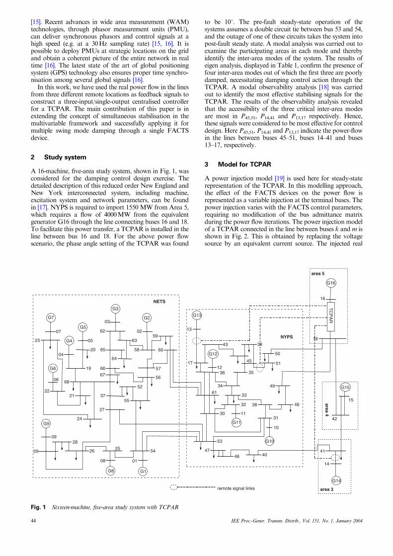
A 16-machine, five-area study system, shown in Fig. 1, wasconsidered for the damping control design exercise. Thedetailed description of this reduced order New England andNew York interconnected system, including machine,excitation system and network parameters, can be foundin [17]. NYPS is required to import 1550 MW from Area 5,which requires a flow of 4000 MW from the equivalentgenerator G16 through the line connecting buses 16 and 18.To facilitate this power transfer, a TCPAR is installed in theline between bus 16 and 18. For the above power flowscenario, the phase angle setting of the TCPAR was found
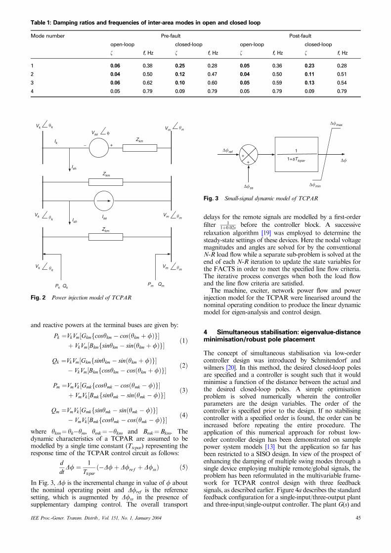
to be 101. The pre-fault steady-state operation of thesystems assumes a double circuit tie between bus 53 and 54,and the outage of one of these circuits takes the system intopost-fault steady state. A modal analysis was carried out toexamine the participating areas in each mode and therebyidentify the inter-area modes of the system. The results ofeigen analysis, displayed in Table 1, confirm the presence offour inter-area modes out of which the first three are poorlydamped, necessitating damping control action through theTCPAR. A modal observability analysis [18] was carriedout to identify the most effective stabilising signals for theTCPAR. The results of the observability analysis revealedthat the accessibility of the three critical inter-area modesare most in P45,51, P14,41 and P13,17 respectively. Hence,these signals were considered to be most effective for controldesign. Here P45,51, P14,41 and P13,17 indicate the power-flowin the lines between buses 45–51, buses 14–41 and buses13–17, respectively.
3 Model for TCPAR
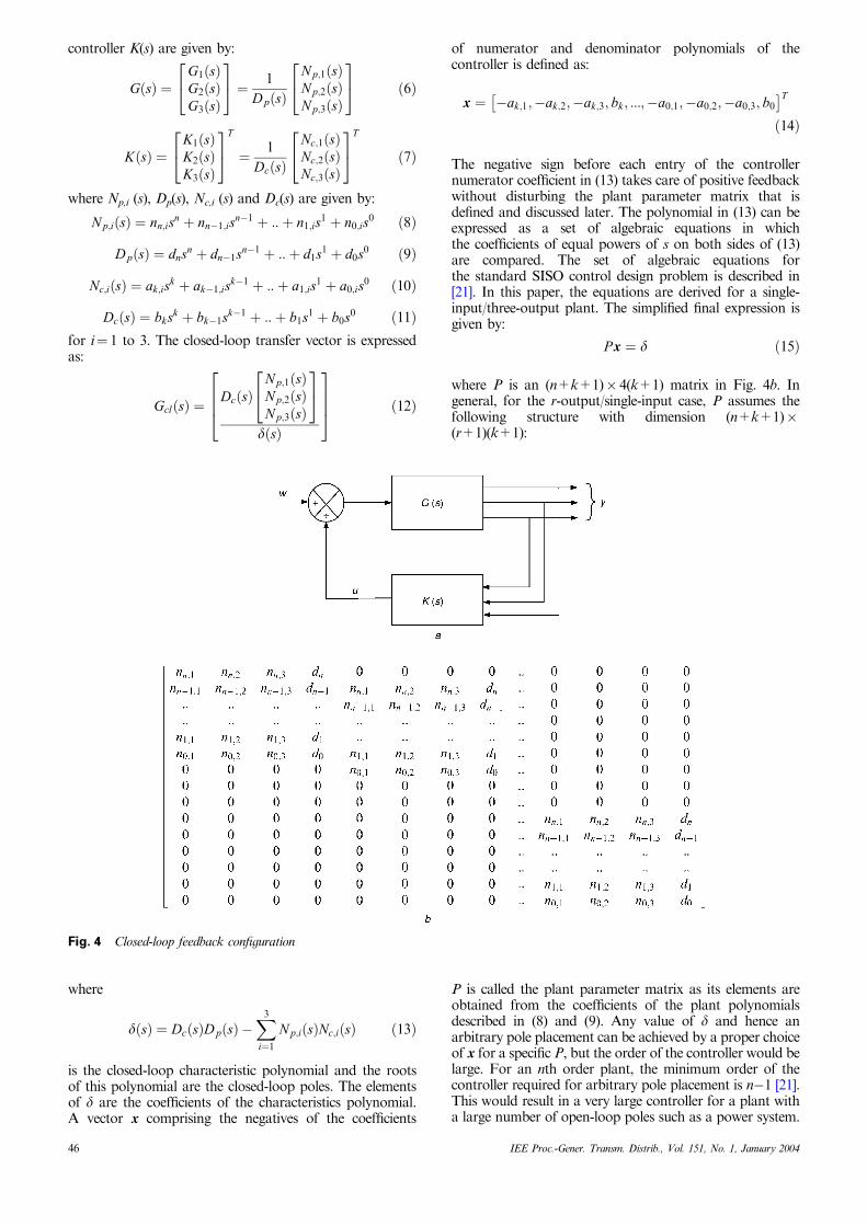
A power injection model [19] is used here for steady-staterepresentation of the TCPAR. In this modelling approach,the effect of the FACTS devices on the power flow isrepresented as a variable injection at the terminal buses. Thepower injection varies with the FACTS control parameters,requiring no modification of the bus admittance matrixduring the power flow iterations. The power injection modelof a TCPAR connected in the line between buses k and m isshown in Fig. 2. This is obtained by replacing the voltagesource by an equivalent current source. The injected real
G703
G9
G6
G4
G5
G3
67
22
24
21
19 66
23
06
37
05
07
68
27
64
65
62
26
2809
29
2004
G2
58
56
55
52
02
57
59
60
G8 G1
01
5425
08
63
36
1131
53
51
49
38
30
39
35
33
32
34
43
13
17 4512
46
61
50
48 4047
G12
G13
G10
G11
18
14
15
16
41
42
G14
G15
G16
NETS
NYPS
area 5
area 3
area 4
10
TC
PA
R
remote signal links
Fig. 1 Sixteen-machine, five-area study system with TCPAR
44 IEE Proc.-Gener. Transm. Distrib., Vol. 151, No. 1, January 2004
and reactive powers at the terminal buses are given by:
Pk ¼VkVm Gkm cosykm � cosðykm þ fÞf g½ þ VkVm Bkm sinykm � sinðykm þ fÞf g½
ð1Þ
Qk ¼VkVm Gkm sinykm � sinðykm þ fÞf g½ � VkVm Bkm cosykm � cosðykm þ fÞf g½
ð2Þ
Pm ¼VmVk Gmk cosymk � cosðymk � fÞf g½ þ VmVk Bmk sinymk � sinðymk � fÞf g½
ð3Þ
Qm ¼VmVk Gmk sinymk � sinðymk � fÞf g½ � VmVk Bmk cosymk � cosðymk � fÞf g½
ð4Þ
where ykm¼ yk�ym, ymk¼�ykm and Bmk¼Bkm. Thedynamic characteristics of a TCPAR are assumed to bemodelled by a single time constant (Ttcpar) representing theresponse time of the TCPAR control circuit as follows:
ddtDf ¼ 1
Ttcparð�Dfþ Dfref þ DfssÞ ð5Þ
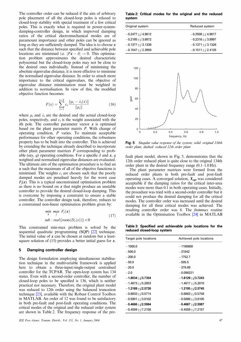
In Fig. 3, Df is the incremental change in value of f aboutthe nominal operating point and Dfref is the referencesetting, which is augmented by Dfss in the presence ofsupplementary damping control. The overall transport
delays for the remote signals are modelled by a first-orderfilter 1
1þ0:02s before the controller block. A successive
relaxation algorithm [19] was employed to determine thesteady-state settings of these devices. Here the nodal voltagemagnitudes and angles are solved for by the conventionalN-R load flow while a separate sub-problem is solved at theend of each N-R iteration to update the state variables forthe FACTS in order to meet the specified line flow criteria.The iterative process converges when both the load flowand the line flow criteria are satisfied.
The machine, exciter, network power flow and powerinjection model for the TCPAR were linearised around thenominal operating condition to produce the linear dynamicmodel for eigen-analysis and control design.
4 Simultaneous stabilisation: eigenvalue-distanceminimisation/robust pole placement
The concept of simultaneous stabilisation via low-ordercontroller design was introduced by Schmitendorf andwilmers [20]. In this method, the desired closed-loop polesare specified and a controller is sought such that it wouldminimise a function of the distance between the actual andthe desired closed-loop poles. A simple optimisationproblem is solved numerically wherein the controllerparameters are the design variables. The order of thecontroller is specified prior to the design. If no stabilisingcontroller with a specified order is found, the order can beincreased before repeating the entire procedure. Theapplication of this numerical approach for robust low-order controller design has been demonstrated on samplepower system models [13] but the application so far hasbeen restricted to a SISO design. In view of the prospect ofenhancing the damping of multiple swing modes through asingle device employing multiple remote/global signals, theproblem has been reformulated in the multivariable frame-work for TCPAR control design with three feedbacksignals, as described earlier. Figure 4a describes the standardfeedback configuration for a single-input/three-output plantand three-input/single-output controller. The plant G(s) and
Table 1: Damping ratios and frequencies of inter-area modes in open and closed loop
Mode number Pre-fault Post-fault
open-loop closed-loop open-loop closed-loop
z f, Hz z f, Hz z f, Hz z f, Hz
1 0.06 0.38 0.25 0.28 0.05 0.36 0.23 0.28
2 0.04 0.50 0.12 0.47 0.04 0.50 0.11 0.51
3 0.06 0.62 0.10 0.60 0.05 0.59 0.13 0.54
4 0.05 0.79 0.09 0.79 0.05 0.79 0.09 0.79
Vk �k Vm �m
Zkm
Vse φ
Zkm
Pk QkPm Qm
Ik
Ish
Ise
Zkm−
Ish
Vk �k
Vk �k
Vm �m
Vm �m
+
Fig. 2 Power injection model of TCPAR
1+sTtcpar
1+
+
∆�ref
∆�ss
∆�
∆�min
∆�max
Fig. 3 Small-signal dynamic model of TCPAR
IEE Proc.-Gener. Transm. Distrib., Vol. 151, No. 1, January 2004 45
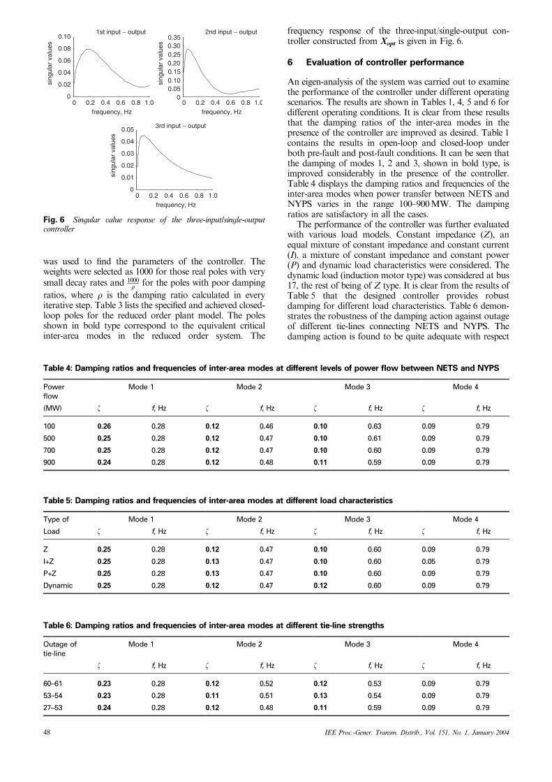
controller K(s) are given by:
GðsÞ ¼G1ðsÞG2ðsÞG3ðsÞ
24
35 ¼ 1
DpðsÞ
Np;1ðsÞNp;2ðsÞNp;3ðsÞ
24
35 ð6Þ
KðsÞ ¼K1ðsÞK2ðsÞK3ðsÞ
24
35T
¼ 1
DcðsÞ
Nc;1ðsÞNc;2ðsÞNc;3ðsÞ
24
35T
ð7Þ
where Np,i (s), Dp(s), Nc,i (s) and Dc(s) are given by:
Np;iðsÞ ¼ nn;isn þ nn�1;isn�1 þ ::þ n1;is1 þ n0;is0 ð8Þ
DpðsÞ ¼ dnsn þ dn�1sn�1 þ ::þ d1s1 þ d0s0 ð9Þ
Nc;iðsÞ ¼ ak;isk þ ak�1;isk�1 þ ::þ a1;is1 þ a0;is0 ð10Þ
DcðsÞ ¼ bksk þ bk�1sk�1 þ ::þ b1s1 þ b0s0 ð11Þfor i¼ 1 to 3. The closed-loop transfer vector is expressedas:
GclðsÞ ¼DcðsÞ
Np;1ðsÞNp;2ðsÞNp;3ðsÞ
24
35
dðsÞ
2664
3775 ð12Þ
where
dðsÞ ¼ DcðsÞDpðsÞ �X3
i¼1
Np;iðsÞNc;iðsÞ ð13Þ
is the closed-loop characteristic polynomial and the rootsof this polynomial are the closed-loop poles. The elementsof d are the coefficients of the characteristics polynomial.A vector x comprising the negatives of the coefficients
of numerator and denominator polynomials of thecontroller is defined as:
x ¼ �ak;1;�ak;2;�ak;3; bk; :::;�a0;1;�a0;2;�a0;3; b0
� Tð14Þ
The negative sign before each entry of the controllernumerator coefficient in (13) takes care of positive feedbackwithout disturbing the plant parameter matrix that isdefined and discussed later. The polynomial in (13) can beexpressed as a set of algebraic equations in whichthe coefficients of equal powers of s on both sides of (13)are compared. The set of algebraic equations forthe standard SISO control design problem is described in[21]. In this paper, the equations are derived for a single-input/three-output plant. The simplified final expression isgiven by:
Px ¼ d ð15Þ
where P is an (n+k+1) 4(k+1) matrix in Fig. 4b. Ingeneral, for the r-output/single-input case, P assumes thefollowing structure with dimension (n+k+1)(r+1)(k+1):
P is called the plant parameter matrix as its elements areobtained from the coefficients of the plant polynomialsdescribed in (8) and (9). Any value of d and hence anarbitrary pole placement can be achieved by a proper choiceof x for a specific P, but the order of the controller would belarge. For an nth order plant, the minimum order of thecontroller required for arbitrary pole placement is n�1 [21].This would result in a very large controller for a plant witha large number of open-loop poles such as a power system.
Fig. 4 Closed-loop feedback configuration
46 IEE Proc.-Gener. Transm. Distrib., Vol. 151, No. 1, January 2004
The controller order can be reduced if the aim of arbitrarypole placement of all the closed-loop poles is relaxed toclosed-loop stability with special treatment of a few criticalpoles. This is exactly what is required in power-system-damping-controller design, in which improved dampingratios of the critical electromechanical modes are ofparamount importance and other poles can be ignored aslong as they are sufficiently damped. The idea is to choose xsuch that the distance between specified and achievable polelocations are minimised i.e. Px � dj j ! 0. This optimisa-tion problem approximates the desired characteristicpolynomial but the closed-loop poles may not be close tothe desired ones individually. Instead of minimising theabsolute eigenvalue distance, it is more effective to minimisethe normalised eigenvalue distance. In order to attach moreimportance to the critical eigenvalues, the objective ofeigenvalue distance minimisation must be weighted inaddition to normalisation. In view of this, the modifiedobjective function becomes:
F ðxÞ ¼Xnþk
i¼1
cimi � liðxÞk k
mik k ð16Þ
where mi and li are the desired and the actual closed-looppoles, respectively, and ci is the weight associated with theith pole. The controller parameter vector x is optimisedbased on the plant parameter matrix P. With change ofoperating condition, P varies. To maintain acceptableperformance for other operating conditions, the robustnessproperty has to be built into the controller. This is achievedby extending the technique already described to incorporateother plant parameter matrices P corresponding to prob-able (say, q) operating conditions. For a specific d and x, qweighted and normalised eigenvalue distances are evaluated.The ultimate aim of the optimisation procedure is to find anx such that the maximum of all of the objective functions isminimised. The weights ci are chosen such that the poorlydamped modes are penalised heavily for the worst caseFj(x). This is a typical unconstrained optimisation problemas there is no bound on x that might produce an unstablecontroller to provide the desired closed-loop damping. Thisis overcome by imposing a constraint to ensure a stablecontroller. The controller design task, therefore, reduces toa constrained non-linear optimisation problem given by:
minx
maxj
FjðxÞ
sub : real rootsðDcðsÞÞf go0ð17Þ
This constrained min-max problem is solved by thesequential quadratic programming (SQP) [22] technique.The initial value of x can be chosen at random but a least-square solution of (15) provides a better initial guess for x.
5 Damping controller design
The design formulation employing simultaneous stabilisa-tion technique in the multivariable framework is appliedhere to obtain a three-input/single-output centralisedcontroller for the TCPAR. The open-loop system has 134states. Even with a second-order controller, the number ofclosed-loop poles to be specified is 136, which is neitherpractical nor necessary. Therefore, the original plant modelwas reduced to 12th order using the balanced truncationtechnique [23], available with the Robust Control Toolboxin MATLAB. An order of 12 was found to be satisfactoryin both pre-fault and post-fault operating conditions. Thecritical modes of the original and the reduced order systemare shown in Table 2. The frequency response of the pre-
fault plant model, shown in Fig. 5, demonstrates that the12th order reduced plant is quite close to the original 134thorder plant in the desired frequency range (0.1–1.0 Hz).
The plant parameter matrices were formed from thereduced order plants in both pre-fault and post-faultoperating cases. A converged solution, Xopt was consideredacceptable if the damping ratios for the critical inter-areamodes were more than 0.1 in both operating cases. Initially,the procedure was tried with a second-order controller but itcould not produce the desired damping for all the criticalmodes. The controller order was increased until the desireddamping for all three critical modes was achieved. Theresulting controller order was 8. The fminmax routineavailable in the Optimisation Toolbox [24] in MATLAB
Table 2: Critical modes for the original and the reducedsystem
Original system Reduced system
�0.24777j 4.9612 �0.25087j 4.9617
�0.21857j 3.8872 �0.23167j 3.8997
�0.13777j 3.1338 �0.13717j 3.1326
�0.15477j 2.3959 �0.15117j 2.4128
0 0.2 0.4 0.6 0.8 1.00
20
40
60
80
100
120
frequency, Hz
gain
Fig. 5 Singular value response of the system; solid: original 134thorder plant, dashed: reduced 12th order plant
Table 3: Specified and achievable pole locations for thereduced closed-loop system
Target pole locations Achieved pole locations
�1000.0 �1190600
�500.0 �31842
�200.0 �1752.7
�50.0 �505.5
�20.0 �378.89
�2.0 �0.098221
�1.80347j 3.7354 �1.81297j 3.7243
�1.46737j 5.2853 �1.46177j 5.2810
�1.21697j 2.5726 �1.21957j 2.5745
�0.68337j 0.5774 �0.68637j 0.5758
�0.59017j 3.8102 �0.58987j 3.8105
�0.46667j 2.5984 �0.46677j 2.5987
�0.45597j 7.2156 �0.45597j 7.2157
IEE Proc.-Gener. Transm. Distrib., Vol. 151, No. 1, January 2004 47
was used to find the parameters of the controller. Theweights were selected as 1000 for those real poles with verysmall decay rates and 1000
r for the poles with poor damping
ratios, where r is the damping ratio calculated in everyiterative step. Table 3 lists the specified and achieved closed-loop poles for the reduced order plant model. The polesshown in bold type correspond to the equivalent criticalinter-area modes in the reduced order system. The
frequency response of the three-input/single-output con-troller constructed from Xopt is given in Fig. 6.
6 Evaluation of controller performance
An eigen-analysis of the system was carried out to examinethe performance of the controller under different operatingscenarios. The results are shown in Tables 1, 4, 5 and 6 fordifferent operating conditions. It is clear from these resultsthat the damping ratios of the inter-area modes in thepresence of the controller are improved as desired. Table 1contains the results in open-loop and closed-loop underboth pre-fault and post-fault conditions. It can be seen thatthe damping of modes 1, 2 and 3, shown in bold type, isimproved considerably in the presence of the controller.Table 4 displays the damping ratios and frequencies of theinter-area modes when power transfer between NETS andNYPS varies in the range 100–900 MW. The dampingratios are satisfactory in all the cases.
The performance of the controller was further evaluatedwith various load models. Constant impedance (Z), anequal mixture of constant impedance and constant current(I), a mixture of constant impedance and constant power(P) and dynamic load characteristics were considered. Thedynamic load (induction motor type) was considered at bus17, the rest of being of Z type. It is clear from the results ofTable 5 that the designed controller provides robustdamping for different load characteristics. Table 6 demon-strates the robustness of the damping action against outageof different tie-lines connecting NETS and NYPS. Thedamping action is found to be quite adequate with respect
0 0.2 0.4 0.6 0.8 1.00
0.02
0.04
0.06
0.08
0.101st input − output
frequency, Hz
sing
ular
val
ues
0 0.2 0.4 0.6 0.8 1.00
0.050.100.150.200.250.300.35
2nd input − output
frequency, Hz
sing
ular
val
ues
0 0.2 0.4 0.6 0.8 1.00
0.01
0.02
0.03
0.04
0.05 3rd input − output
frequency, Hz
sing
ular
val
ues
Fig. 6 Singular value response of the three-input/single-outputcontroller
Table 4: Damping ratios and frequencies of inter-area modes at different levels of power flow between NETS and NYPS
Powerflow
Mode 1 Mode 2 Mode 3 Mode 4
(MW) z f, Hz z f, Hz z f, Hz z f, Hz
100 0.26 0.28 0.12 0.46 0.10 0.63 0.09 0.79
500 0.25 0.28 0.12 0.47 0.10 0.61 0.09 0.79
700 0.25 0.28 0.12 0.47 0.10 0.60 0.09 0.79
900 0.24 0.28 0.12 0.48 0.11 0.59 0.09 0.79
Table 5: Damping ratios and frequencies of inter-area modes at different load characteristics
Type of Mode 1 Mode 2 Mode 3 Mode 4
Load z f, Hz z f, Hz z f, Hz z f, Hz
Z 0.25 0.28 0.12 0.47 0.10 0.60 0.09 0.79
I+Z 0.25 0.28 0.13 0.47 0.10 0.60 0.05 0.79
P+Z 0.25 0.28 0.13 0.47 0.10 0.60 0.09 0.79
Dynamic 0.25 0.28 0.12 0.47 0.12 0.60 0.09 0.79
Table 6: Damping ratios and frequencies of inter-area modes at different tie-line strengths
Outage oftie-line
Mode 1 Mode 2 Mode 3 Mode 4
z f, Hz z f, Hz z f, Hz z f, Hz
60–61 0.23 0.28 0.12 0.52 0.12 0.53 0.09 0.79
53–54 0.23 0.28 0.11 0.51 0.13 0.54 0.09 0.79
27–53 0.24 0.28 0.12 0.48 0.11 0.59 0.09 0.79
48 IEE Proc.-Gener. Transm. Distrib., Vol. 151, No. 1, January 2004
to the outage of each of the tie-lines between buses 27–53,buses 60–61 and buses 53–54 connecting NETS and NYPS.The damping performance of the designed controller is thusobserved to be robust against these varying operatingconditions. One of the concerns of centralised design usingremote signals is possible loss of one of the channels leadingto unsatisfactory damping performance. Mekki et al. [25]have proposed a solution for this based on the replacementof the lost remote signal by a similar local signal through theuse of a signal-loss detector. It is possible to adjust the phasecharacteristics of the replacement local signal by a pre-filter.
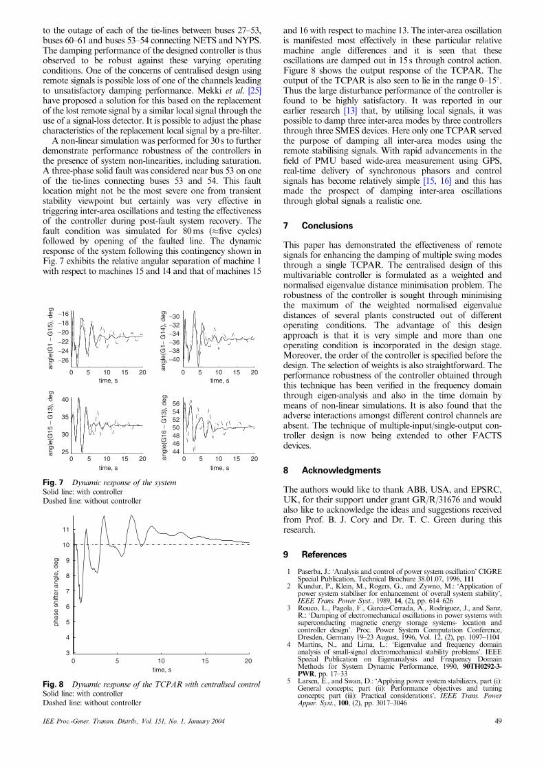
A non-linear simulation was performed for 30 s to furtherdemonstrate performance robustness of the controllers inthe presence of system non-linearities, including saturation.A three-phase solid fault was considered near bus 53 on oneof the tie-lines connecting buses 53 and 54. This faultlocation might not be the most severe one from transientstability viewpoint but certainly was very effective intriggering inter-area oscillations and testing the effectivenessof the controller during post-fault system recovery. Thefault condition was simulated for 80 ms (�five cycles)followed by opening of the faulted line. The dynamicresponse of the system following this contingency shown inFig. 7 exhibits the relative angular separation of machine 1with respect to machines 15 and 14 and that of machines 15
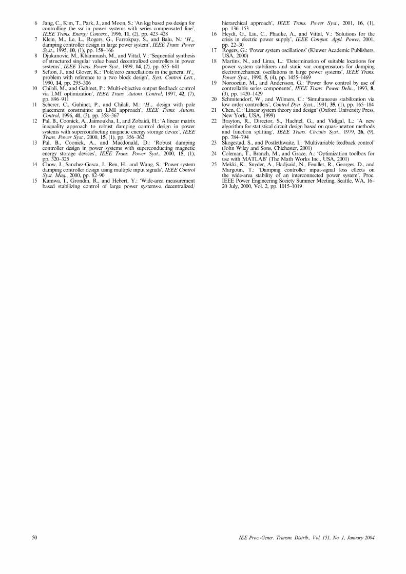
and 16 with respect to machine 13. The inter-area oscillationis manifested most effectively in these particular relativemachine angle differences and it is seen that theseoscillations are damped out in 15 s through control action.Figure 8 shows the output response of the TCPAR. Theoutput of the TCPAR is also seen to lie in the range 0–151.Thus the large disturbance performance of the controller isfound to be highly satisfactory. It was reported in ourearlier research [13] that, by utilising local signals, it waspossible to damp three inter-area modes by three controllersthrough three SMES devices. Here only one TCPAR servedthe purpose of damping all inter-area modes using theremote stabilising signals. With rapid advancements in thefield of PMU based wide-area measurement using GPS,real-time delivery of synchronous phasors and controlsignals has become relatively simple [15, 16] and this hasmade the prospect of damping inter-area oscillationsthrough global signals a realistic one.
7 Conclusions
This paper has demonstrated the effectiveness of remotesignals for enhancing the damping of multiple swing modesthrough a single TCPAR. The centralised design of thismultivariable controller is formulated as a weighted andnormalised eigenvalue distance minimisation problem. Therobustness of the controller is sought through minimisingthe maximum of the weighted normalised eigenvaluedistances of several plants constructed out of differentoperating conditions. The advantage of this designapproach is that it is very simple and more than oneoperating condition is incorporated in the design stage.Moreover, the order of the controller is specified before thedesign. The selection of weights is also straightforward. Theperformance robustness of the controller obtained throughthis technique has been verified in the frequency domainthrough eigen-analysis and also in the time domain bymeans of non-linear simulations. It is also found that theadverse interactions amongst different control channels areabsent. The technique of multiple-input/single-output con-troller design is now being extended to other FACTSdevices.
8 Acknowledgments
The authors would like to thank ABB, USA, and EPSRC,UK, for their support under grant GR/R/31676 and wouldalso like to acknowledge the ideas and suggestions receivedfrom Prof. B. J. Cory and Dr. T. C. Green during thisresearch.
9 References
1 Paserba, J.: ‘Analysis and control of power system oscillation’ CIGRESpecial Publication, Technical Brochure 38.01.07, 1996, 111
2 Kundur, P., Klein, M., Rogers, G., and Zywno, M.: ‘Application ofpower system stabiliser for enhancement of overall system stability’,IEEE Trans. Power Syst., 1989, 14, (2), pp. 614–626
3 Rouco, L., Pagola, F., Garcia-Cerrada, A., Rodriguez, J., and Sanz,R.: ‘Damping of electromechanical oscillations in power systems withsuperconducting magnetic energy storage systems- location andcontroller design’. Proc. Power System Computation Conference,Dresden, Germany 19–23 August, 1996, Vol. 12, (2), pp. 1097–1104
4 Martins, N., and Lima, L.: ‘Eigenvalue and frequency domainanalysis of small-signal electromechanical stability problems’. IEEESpecial Publication on Eigenanalysis and Frequency DomainMethods for System Dynamic Performance, 1990, 90TH0292-3-PWR, pp. 17–33
5 Larsen, E., and Swan, D.: ‘Applying power system stabilizers, part (i):General concepts; part (ii): Performance objectives and tuningconcepts; part (iii): Practical considerations’, IEEE Trans. PowerAppar. Syst., 100, (2), pp. 3017–3046
0 5 10 15 20
−26
−24
−22
−20
−18
−16
angl
e(G
1 −
G15
), d
eg
time, s0 5 10 15 20
−40−38−36−34−32−30
angl
e(G
1− G
14),
deg
time, s
0 5 10 15 2025
30
35
40
angl
e(G
15 −
G13
), d
eg
time, s0 5 10 15 20
44464850525456
angl
e(G
16 −
G13
), d
eg
time, s
Fig. 7 Dynamic response of the systemSolid line: with controllerDashed line: without controller
0 5 10 15 203
4
5
6
7
8
9
10
11
time, s
phas
e sh
ifter
ang
le, d
eg
Fig. 8 Dynamic response of the TCPAR with centralised controlSolid line: with controllerDashed line: without controller
IEE Proc.-Gener. Transm. Distrib., Vol. 151, No. 1, January 2004 49
6 Jang, C., Kim, T., Park, J., and Moon, S.: ‘An lqg based pss design forcontrolling the ssr in power systems with series compensated line’,IEEE Trans. Energy Convers., 1996, 11, (2), pp. 423–428
7 Klein, M., Le, L., Rogers, G., Farrokpay, S., and Balu, N.: ‘HN
damping controller design in large power system’, IEEE Trans. PowerSyst., 1995, 10, (1), pp. 158–166
8 Djukanovic, M., Khammash, M., and Vittal, V.: ‘Sequential synthesisof structured singular value based decentralized controllers in powersystems’, IEEE Trans. Power Syst., 1999, 14, (2), pp. 635–641
9 Sefton, J., and Glover, K.: ‘Pole/zero cancellations in the general HN
problem with reference to a two block design’, Syst. Control Lett.,1990, 14, pp. 295–306
10 Chilali, M., and Gahinet, P.: ‘Multi-objective output feedback controlvia LMI optimization’, IEEE Trans. Autom. Control, 1997, 42, (7),pp. 896–911
11 Scherer, C., Gahinet, P., and Chilali, M.: ‘HN design with poleplacement constraints: an LMI approach’, IEEE Trans. Autom.Control, 1996, 41, (3), pp. 358–367
12 Pal, B., Coonick, A., Jaimoukha, I., and Zobaidi, H.: ‘A linear matrixinequality approach to robust damping control design in powersystems with superconducting magnetic energy storage device’, IEEETrans. Power Syst., 2000, 15, (1), pp. 356–362
13 Pal, B., Coonick, A., and Macdonald, D.: ‘Robust dampingcontroller design in power systems with superconducting magneticenergy storage devices’, IEEE Trans. Power Syst., 2000, 15, (1),pp. 320–325
14 Chow, J., Sanchez-Gasca, J., Ren, H., and Wang, S.: ‘Power systemdamping controller design using multiple input signals’, IEEE ControlSyst. Mag., 2000, pp. 82–90
15 Kamwa, I., Grondin, R., and Hebert, Y.: ‘Wide-area measurementbased stabilizing control of large power systems-a decentralized/
hierarchical approach’, IEEE Trans. Power Syst., 2001, 16, (1),pp. 136–153
16 Heydt, G., Liu, C., Phadke, A., and Vittal, V.: ‘Solutions for thecrisis in electric power supply’, IEEE Comput. Appl. Power, 2001,pp. 22–30
17 Rogers, G.: ‘Power system oscillations’ (Kluwer Academic Publishers,USA, 2000)
18 Martins, N., and Lima, L.: ‘Determination of suitable locations forpower system stabilizers and static var compensators for dampingelectromechanical oscillations in large power systems’, IEEE Trans.Power Syst., 1990, 5, (4), pp. 1455–1469
19 Noroozian, M., and Andersson, G.: ‘Power flow control by use ofcontrollable series components’, IEEE Trans. Power Deliv., 1993, 8,(3), pp. 1420–1429
20 Schmitendorf, W., and Wilmers, C.: ‘Simultaneous stabilization vialow order controllers’, Control Dyn. Syst., 1991, 35, (1), pp. 165–184
21 Chen, C.: ‘Linear system theory and design’ (Oxford University Press,New York, USA, 1999)
22 Brayton, R., Director, S., Hachtel, G., and Vidigal, L.: ‘A newalgorithm for statistical circuit design based on quasi-newton methodsand function splitting’, IEEE Trans. Circuits Syst., 1979, 26, (9),pp. 784–794
23 Skogestad, S., and Postlethwaite, I.: ‘Multivariable feedback control’(John Wiley and Sons, Chichester, 2001)
24 Coleman, T., Branch, M., and Grace, A.: ‘Optimization toolbox foruse with MATLAB’ (The Math Works Inc., USA, 2001)
25 Mekki, K., Snyder, A., Hadjsaid, N., Feuillet, R., Georges, D., andMargotin, T.: ‘Damping controller input-signal loss effects onthe wide-area stability of an interconnected power system’. Proc.IEEE Power Engineering Society Summer Meeting, Seattle, WA, 16–20 July, 2000, Vol. 2, pp. 1015–1019
50 IEE Proc.-Gener. Transm. Distrib., Vol. 151, No. 1, January 2004