Embed Size (px)
Citation preview
1
Simultaneous Removal of SO2 and CO2 From Flue Gases at Large Coal-Fired Stationary Sources
Y. F. Khalil(1) and AJ Gerbino(2)
(1) Chemical Engineering Department, Yale University, New Haven, CT 06520
(2) AQSim, Inc., Glen Ridge, NJ 07028
OLI’s 24th User Conference
Hyatt Hotel, Morristown, NJ
October 23 – 24, 2007
2
Presentation Outline
Motivation for developing alternative technologies for CO2 capture:
- U.S. GCCI
- Integrated control technologies (ICTs)
- Technical and economic barriers of CO2 capture using MEA
Research objectives
Research apporach for modeling CO2 and SO2 capture using:
- OLIs’ ESP
- ICEM (DOE model)
Results and discussion: IECM and ESP
Summary
Roadmap for future work
33
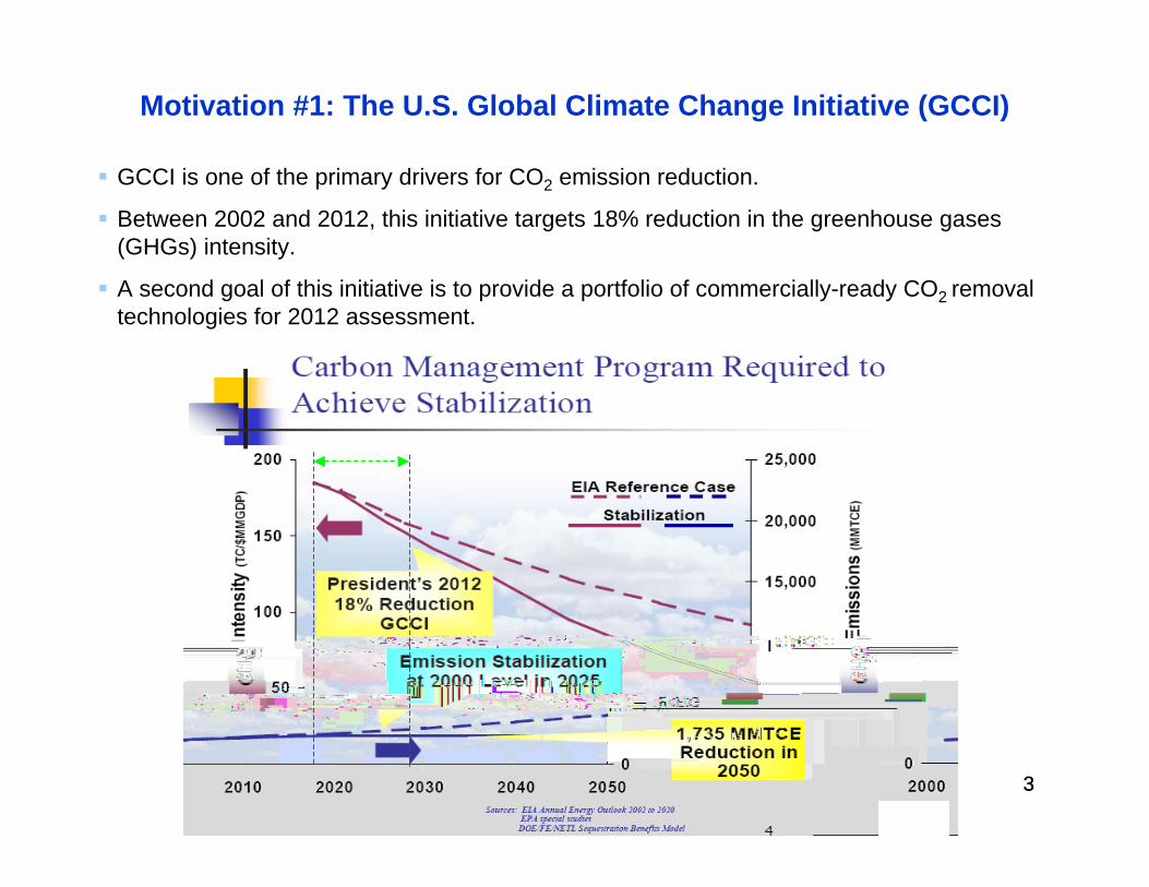
Motivation #1: The U.S. Global Climate Change Initiative (GCCI)
GCCI is one of the primary drivers for CO2 emission reduction.
Between 2002 and 2012, this initiative targets 18% reduction in the greenhouse gases (GHGs) intensity.
A second goal of this initiative is to provide a portfolio of commercially-ready CO2 removal technologies for 2012 assessment.
4
Motivation #2: Integrated Control Technologies (ICTs)
More cost effective compared to single-effect technologies
Less footprint and, hence, easier to retrofit
Possibility of sharing some unit operations
Possibility of shared raw materials
Example: simultaneous removal of CO2 and SO2
5
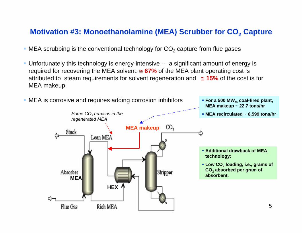
Motivation #3: Monoethanolamine (MEA) Scrubber for CO2 Capture
MEA scrubbing is the conventional technology for CO2 capture from flue gases
Unfortunately this technology is energy-intensive -- a significant amount of energy is required for recovering the MEA solvent: ≅ 67% of the MEA plant operating cost is attributed to steam requirements for solvent regeneration and ≅ 15% of the cost is for MEA makeup.
MEA is corrosive and requires adding corrosion inhibitors
MEAHEX
MEA makeup
Some CO2 remains in the regenerated MEA
Additional drawback of MEA technology:
Low CO2 loading, i.e., grams of CO2 absorbed per gram of absorbent.
For a 500 MWth coal-fired plant, MEA makeup ~ 22.7 tons/hr
MEA recirculated ~ 6,599 tons/hr
6
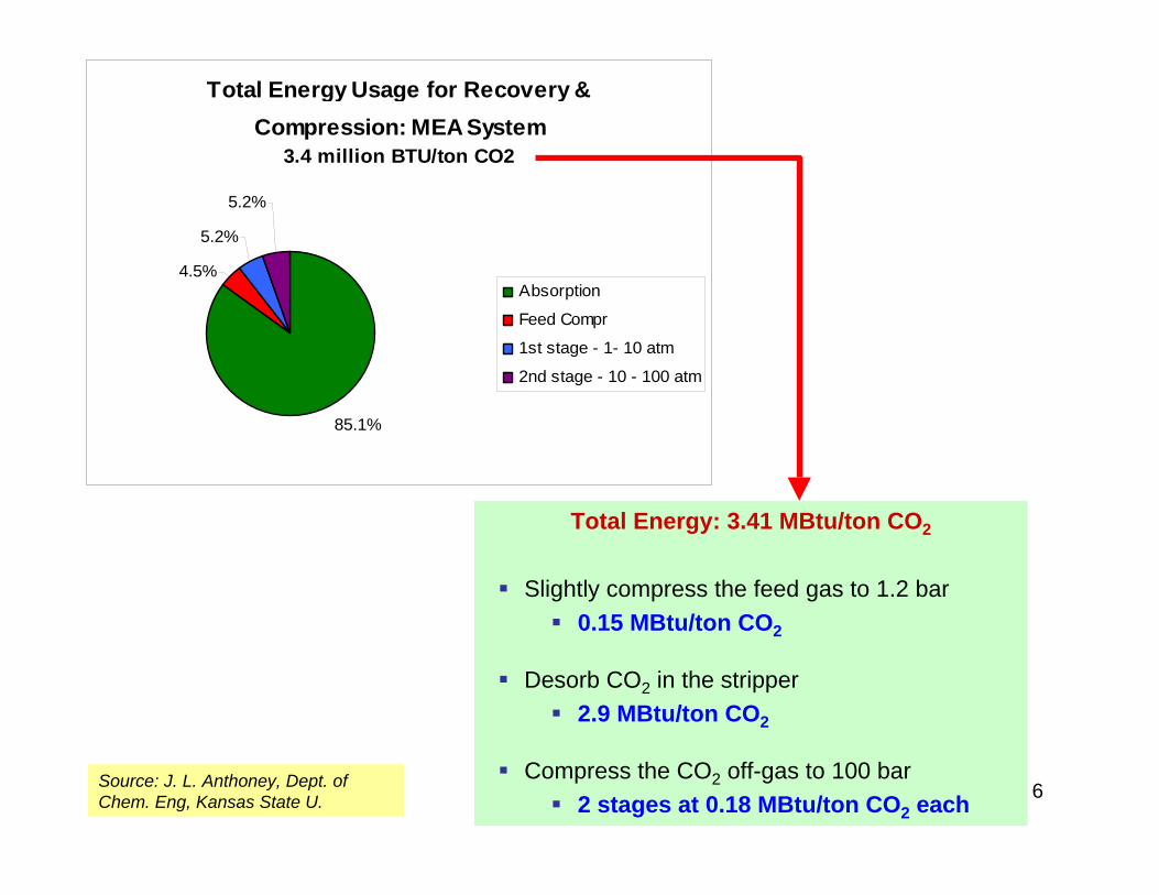
Total Energy Usage for Recovery & Compression: MEA System
3.4 million BTU/ton CO2
85.1%
4.5%
5.2%
5.2%
Absorption
Feed Compr
1st stage - 1- 10 atm
2nd stage - 10 - 100 atm
Total Energy: 3.41 MBtu/ton CO2
Slightly compress the feed gas to 1.2 bar 0.15 MBtu/ton CO2
Desorb CO2 in the stripper 2.9 MBtu/ton CO2
Compress the CO2 off-gas to 100 bar 2 stages at 0.18 MBtu/ton CO2 each
Source: J. L. Anthoney, Dept. of Chem. Eng, Kansas State U.
7
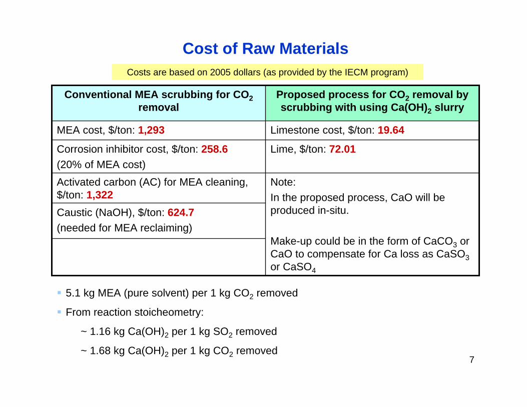
Caustic (NaOH), $/ton: 624.7(needed for MEA reclaiming)
Note:In the proposed process, CaO will be produced in-situ.
Make-up could be in the form of CaCO3 or CaO to compensate for Ca loss as CaSO3or CaSO4
Activated carbon (AC) for MEA cleaning, $/ton: 1,322
Lime, $/ton: 72.01Corrosion inhibitor cost, $/ton: 258.6(20% of MEA cost)
Limestone cost, $/ton: 19.64MEA cost, $/ton: 1,293
Proposed process for CO2 removal by scrubbing with using Ca(OH)2 slurry
Conventional MEA scrubbing for CO2removal
Costs are based on 2005 dollars (as provided by the IECM program)
Cost of Raw Materials
5.1 kg MEA (pure solvent) per 1 kg CO2 removed
From reaction stoicheometry:
~ 1.16 kg Ca(OH)2 per 1 kg SO2 removed
~ 1.68 kg Ca(OH)2 per 1 kg CO2 removed
88
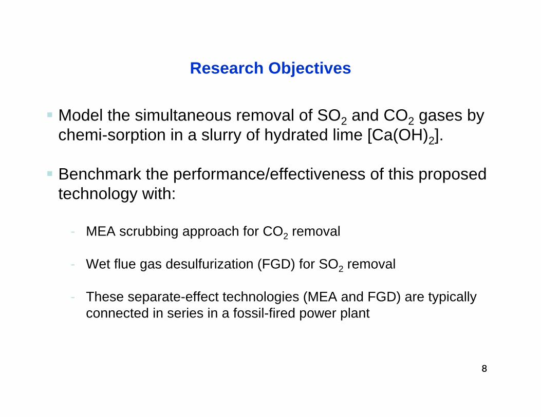
Research Objectives
Model the simultaneous removal of SO2 and CO2 gases by chemi-sorption in a slurry of hydrated lime [Ca(OH)2].
Benchmark the performance/effectiveness of this proposed technology with:
- MEA scrubbing approach for CO2 removal
- Wet flue gas desulfurization (FGD) for SO2 removal
- These separate-effect technologies (MEA and FGD) are typically connected in series in a fossil-fired power plant
99
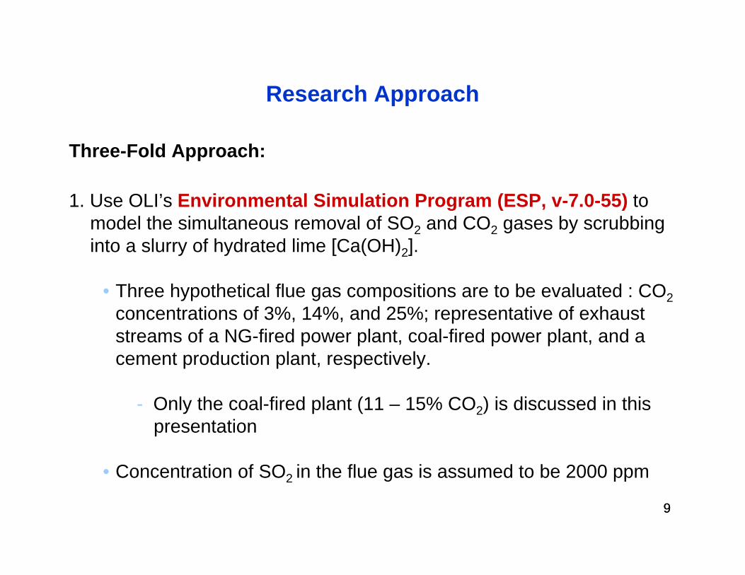
Research Approach
1. Use OLI’s Environmental Simulation Program (ESP, v-7.0-55) to model the simultaneous removal of SO2 and CO2 gases by scrubbing into a slurry of hydrated lime [Ca(OH)2].
• Three hypothetical flue gas compositions are to be evaluated : CO2concentrations of 3%, 14%, and 25%; representative of exhaust streams of a NG-fired power plant, coal-fired power plant, and a cement production plant, respectively.
- Only the coal-fired plant (11 – 15% CO2) is discussed in this presentation
• Concentration of SO2 in the flue gas is assumed to be 2000 ppm
Three-Fold Approach:
1010
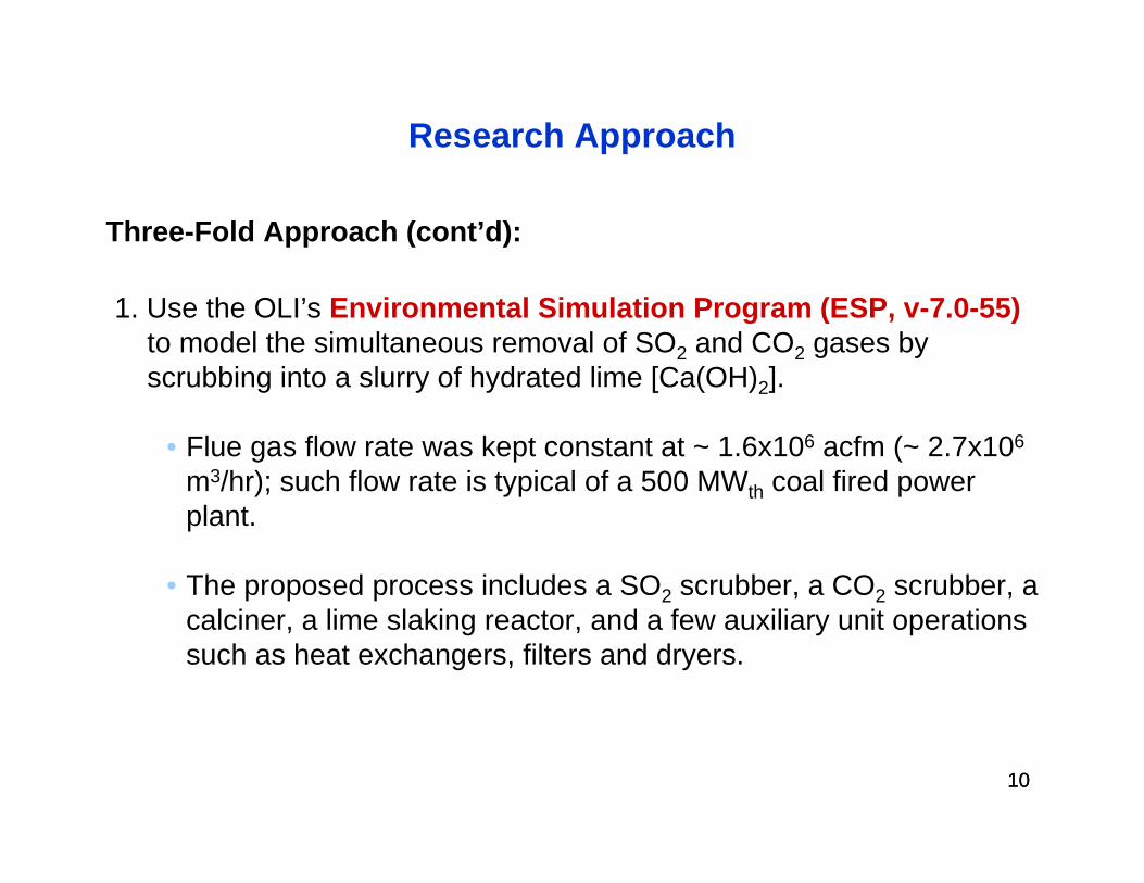
Research Approach
1. Use the OLI’s Environmental Simulation Program (ESP, v-7.0-55)to model the simultaneous removal of SO2 and CO2 gases by scrubbing into a slurry of hydrated lime [Ca(OH)2].
• Flue gas flow rate was kept constant at ~ 1.6x10⁶ acfm (~ 2.7x10⁶
m3/hr); such flow rate is typical of a 500 MWth coal fired power plant.
• The proposed process includes a SO2 scrubber, a CO2 scrubber, a calciner, a lime slaking reactor, and a few auxiliary unit operations such as heat exchangers, filters and dryers.
Three-Fold Approach (cont’d):
1111
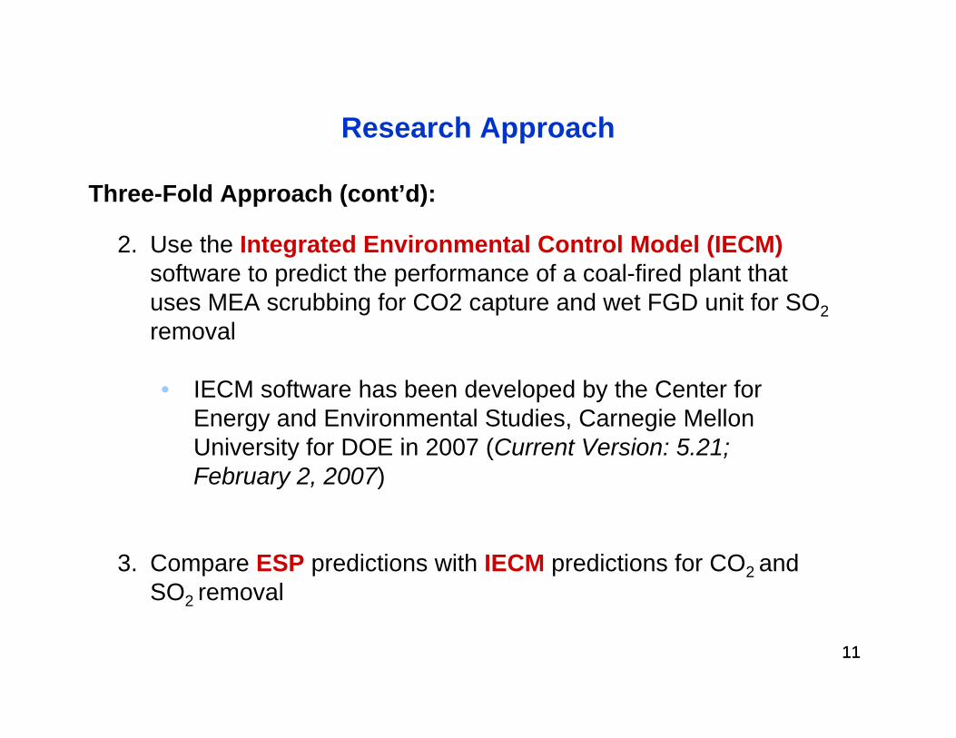
Research Approach
2. Use the Integrated Environmental Control Model (IECM)software to predict the performance of a coal-fired plant that uses MEA scrubbing for CO2 capture and wet FGD unit for SO2removal
• IECM software has been developed by the Center for Energy and Environmental Studies, Carnegie Mellon University for DOE in 2007 (Current Version: 5.21; February 2, 2007)
3. Compare ESP predictions with IECM predictions for CO2 and SO2 removal
Three-Fold Approach (cont’d):
1212
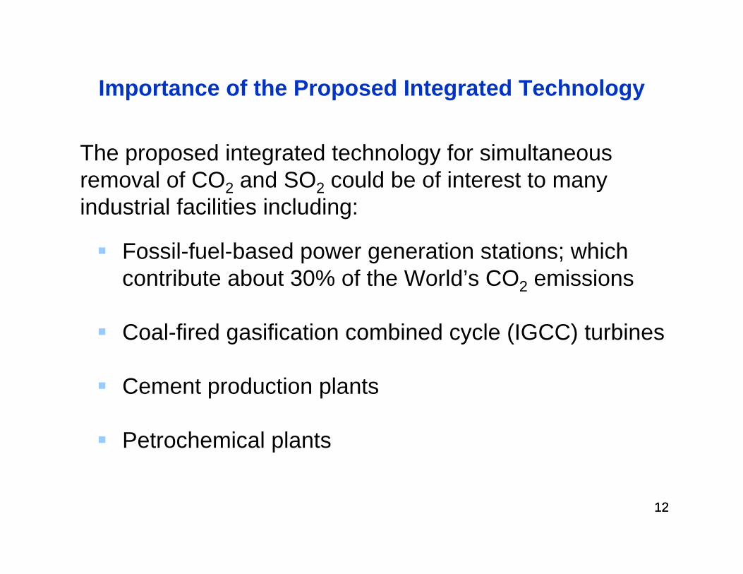
Importance of the Proposed Integrated Technology
Fossil-fuel-based power generation stations; which contribute about 30% of the World’s CO2 emissions
Coal-fired gasification combined cycle (IGCC) turbines
Cement production plants
Petrochemical plants
The proposed integrated technology for simultaneous removal of CO2 and SO2 could be of interest to many industrial facilities including:
1313
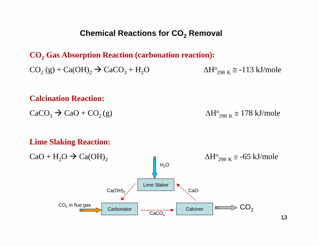
CO2 Gas Absorption Reaction (carbonation reaction):
CO2 (g) + Ca(OH)2 CaCO3 + H2O ΔHo298 K ≅ -113 kJ/mole
Calcination Reaction:
CaCO3 CaO + CO2 (g) ΔHo298 K ≅ 178 kJ/mole
Lime Slaking Reaction:
CaO + H2O Ca(OH)2 ΔHo298 K ≅ -65 kJ/mole
Chemical Reactions for CO2 Removal
Lime Slaker
CalcinerCarbonator CO2
H2O
CO2 in flue gas
CaCO3
CaOCa(OH)2
14
1515
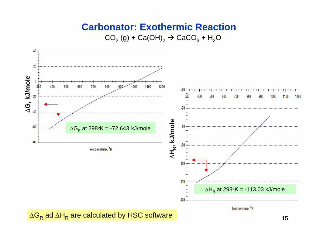
Carbonator: Exothermic ReactionΔ
G, k
J/m
ole
ΔGR ad ΔHR are calculated by HSC software
CO2 (g) + Ca(OH)2 CaCO3 + H2O
ΔGR at 298oK = -72.643 kJ/mole
ΔHR, k
J/m
ole
ΔHR at 298oK = -113.03 kJ/mole
1616
ΔG
, kJ/
mol
e
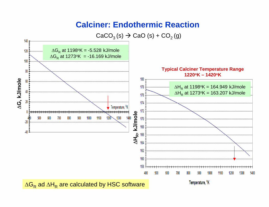
CaCO3 (s) CaO (s) + CO2 (g)
Calciner: Endothermic Reaction
ΔGR at 1198oK = -5.528 kJ/moleΔGR at 1273oK = -16.169 kJ/mole
ΔHR, k
J/m
ole
ΔHR at 1198oK = 164.949 kJ/moleΔHR at 1273oK = 163.207 kJ/mole
Typical Calciner Temperature Range 1220oK – 1420oK
ΔGR ad ΔHR are calculated by HSC software
1717
ΔG
, kJ/
mol
e
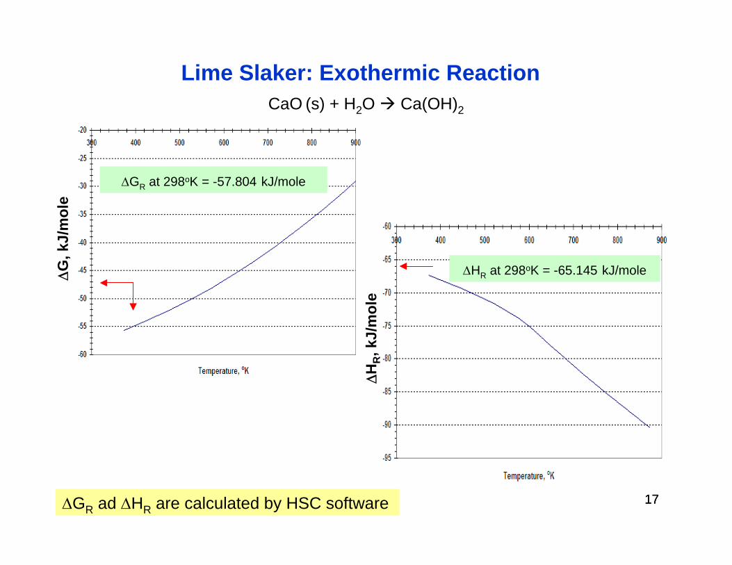
CaO (s) + H2O Ca(OH)2
Lime Slaker: Exothermic Reaction
ΔGR at 298oK = -57.804 kJ/mole
ΔHR, k
J/m
ole
ΔHR at 298oK = -65.145 kJ/mole
ΔGR ad ΔHR are calculated by HSC software
1818
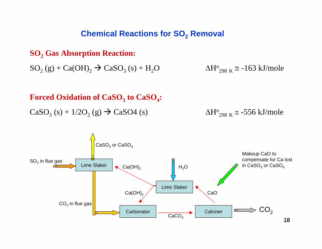
SO2 Gas Absorption Reaction:
SO2 (g) + Ca(OH)2 CaSO3 (s) + H2O ΔHo298 K ≅ -163 kJ/mole
Forced Oxidation of CaSO3 to CaSO4:
CaSO3 (s) + 1/2O2 (g) CaSO4 (s) ΔHo298 K ≅ -556 kJ/mole
Chemical Reactions for SO2 Removal
18
Lime Slaker
CalcinerCarbonator CO2
H2O
CO2 in flue gas
CaCO3
CaOCa(OH)2
Lime SlakerSO2 in flue gas
Ca(OH)2
CaSO3 or CaSO4
Makeup CaO to compensate for Ca lost in CaSO3 or CaSO4
1919
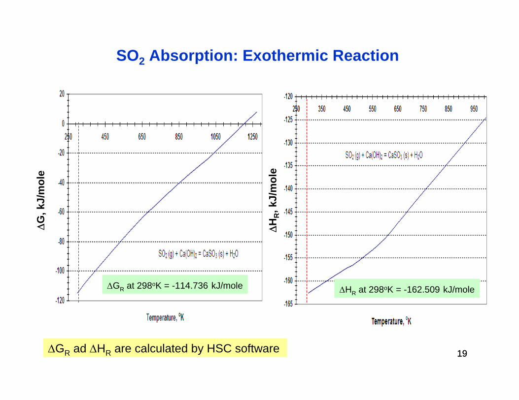
SO2 Absorption: Exothermic ReactionΔ
G, k
J/m
ole
ΔGR at 298oK = -114.736 kJ/mole
ΔGR ad ΔHR are calculated by HSC software
ΔHR, k
J/m
ole
ΔHR at 298oK = -162.509 kJ/mole
2020
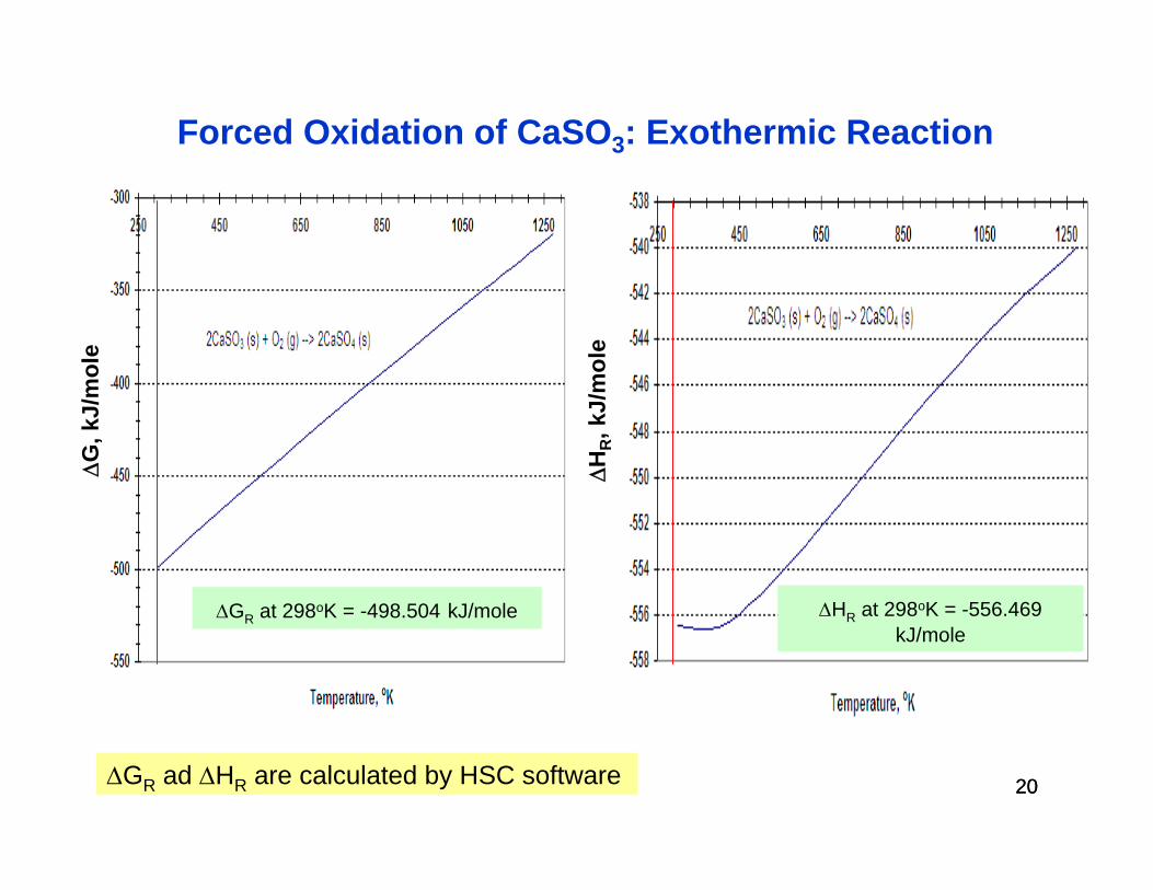
Forced Oxidation of CaSO3: Exothermic ReactionΔ
G, k
J/m
ole
ΔGR at 298oK = -498.504 kJ/moleΔH
R, k
J/m
ole
ΔHR at 298oK = -556.469kJ/mole
ΔGR ad ΔHR are calculated by HSC software
2121
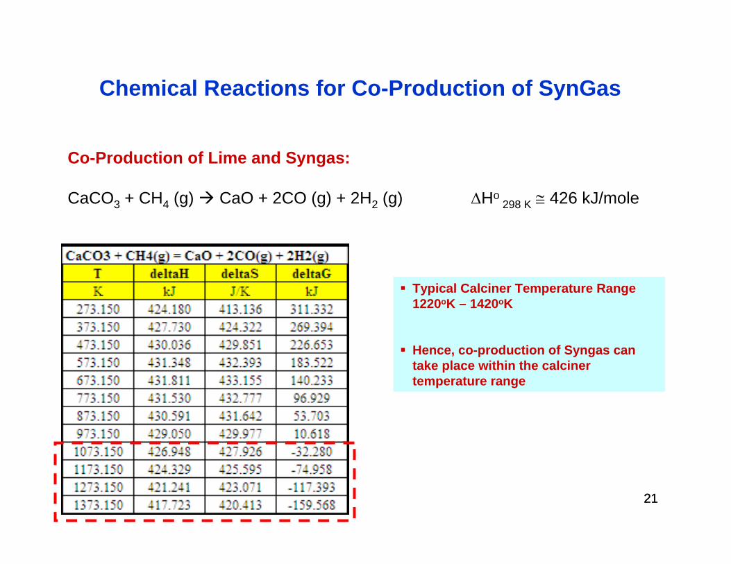
Co-Production of Lime and Syngas:
CaCO3 + CH4 (g) CaO + 2CO (g) + 2H2 (g) ΔHo 298 K ≅ 426 kJ/mole
Chemical Reactions for Co-Production of SynGas
Typical Calciner Temperature Range 1220oK – 1420oK
Hence, co-production of Syngas can take place within the calciner temperature range
2222
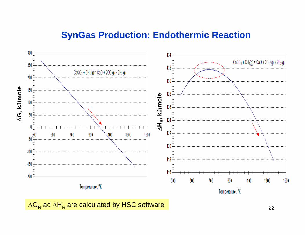
SynGas Production: Endothermic Reaction
ΔG
, kJ/
mol
e
ΔHR, k
J/m
ole
ΔGR ad ΔHR are calculated by HSC software
2323
Mitigation of Operating Risks of the Calciner
Lime Sintering (decrease in surface area and pore size of CaO)
Reducing the operating temperature of the calciner results in less sintering of the produced calcium oxide and, hence, more reactive lime (CaO) in the lime slaker.
Cost of CaO Makeup Due to Loss of Reactivity
Because calcium is used continuously in a cyclical manner, sintering and corresponding reduction in reactivity is a cumulative process that may require periodic makeup of calcium oxide. If calcium can be recycled say 500 times, then it may easily be considered to be cost effective.
24
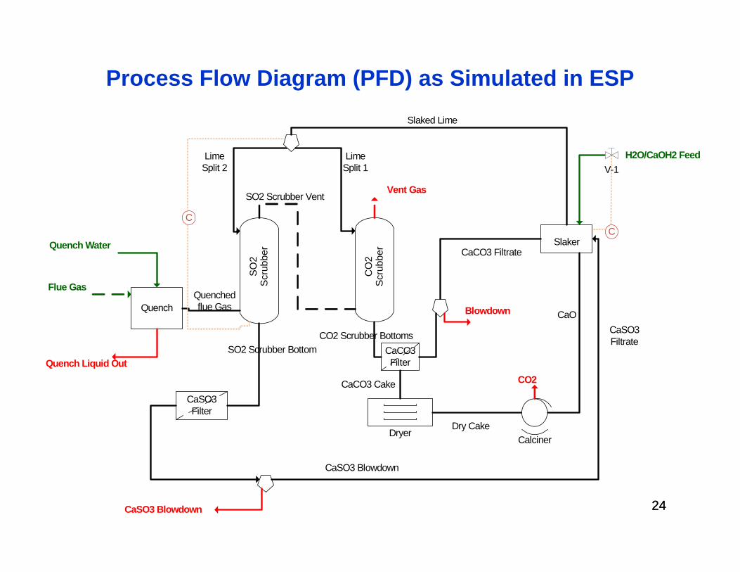
Process Flow Diagram (PFD) as Simulated in ESP
24
Quench
SO2
Scr
ubbe
r
CO
2 S
crub
ber
CaSO3Filter
CaCO3 Filter
Dryer
SlakerQuench Water
Flue Gas
Quench Liquid Out
Quenched flue Gas
SO2 Scrubber Bottom
Lime Split 2
SO2 Scrubber Vent
CO2 Scrubber Bottoms
Vent Gas
Lime Split 1
Slaked Lime
CaCO3 Cake
Dry CakeCalciner
CO2
CaCO3 Filtrate
Blowdown
CaSO3 Blowdown
CaSO3 Filtrate
CaSO3 Blowdown
H2O/CaOH2 Feed
CC
V-1
CaO
25
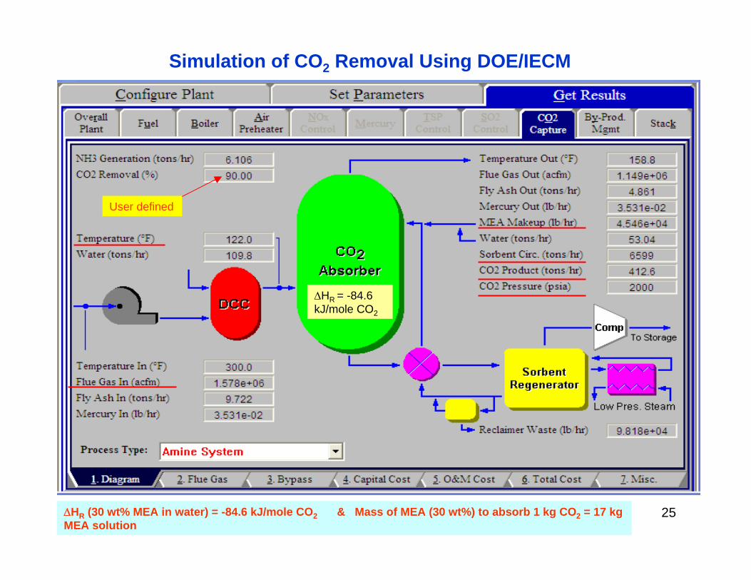
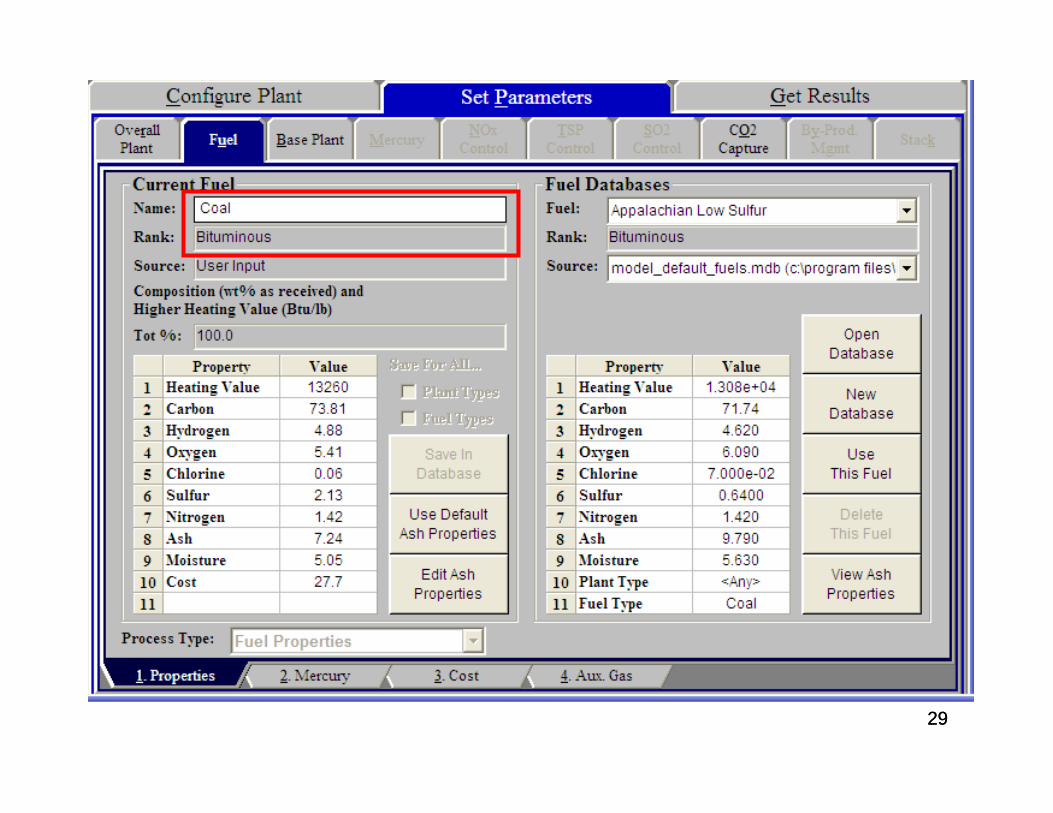
User defined
ΔHR = -84.6 kJ/mole CO2
ΔHR (30 wt% MEA in water) = -84.6 kJ/mole CO2 & Mass of MEA (30 wt%) to absorb 1 kg CO2 = 17 kg MEA solution
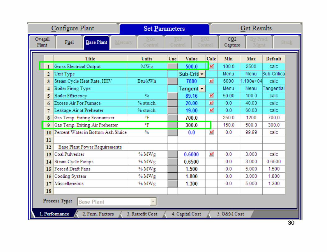
Simulation of CO2 Removal Using DOE/IECM
26
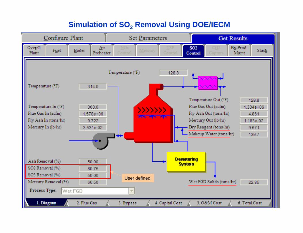
Simulation of SO2 Removal Using DOE/IECM
User defined
2727
Simulation Results of MEA-Based Technology for CO2 Removal Using the Integrated Environmental
Control Module (IECM)
2828
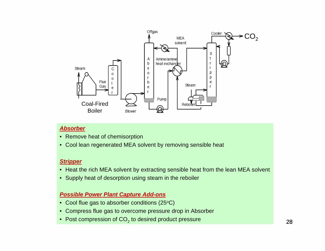
Coal-Fired Boiler
Absorber• Remove heat of chemisorption • Cool lean regenerated MEA solvent by removing sensible heat
Stripper• Heat the rich MEA solvent by extracting sensible heat from the lean MEA solvent• Supply heat of desorption using steam in the reboiler
Possible Power Plant Capture Add-ons• Cool flue gas to absorber conditions (25oC)• Compress flue gas to overcome pressure drop in Absorber• Post compression of CO2 to desired product pressure
CO2
2929
3030
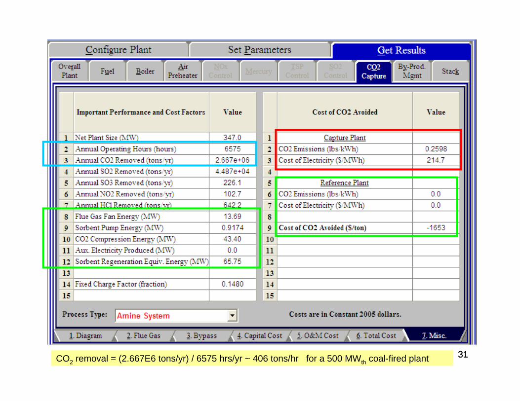
3131CO2 removal = (2.667E6 tons/yr) / 6575 hrs/yr ~ 406 tons/hr for a 500 MWth coal-fired plant
3232
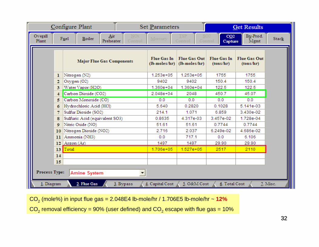
CO2 (mole%) in input flue gas = 2.048E4 lb-mole/hr / 1.706E5 lb-mole/hr ~ 12%
CO2 removal efficiency = 90% (user defined) and CO2 escape with flue gas = 10%
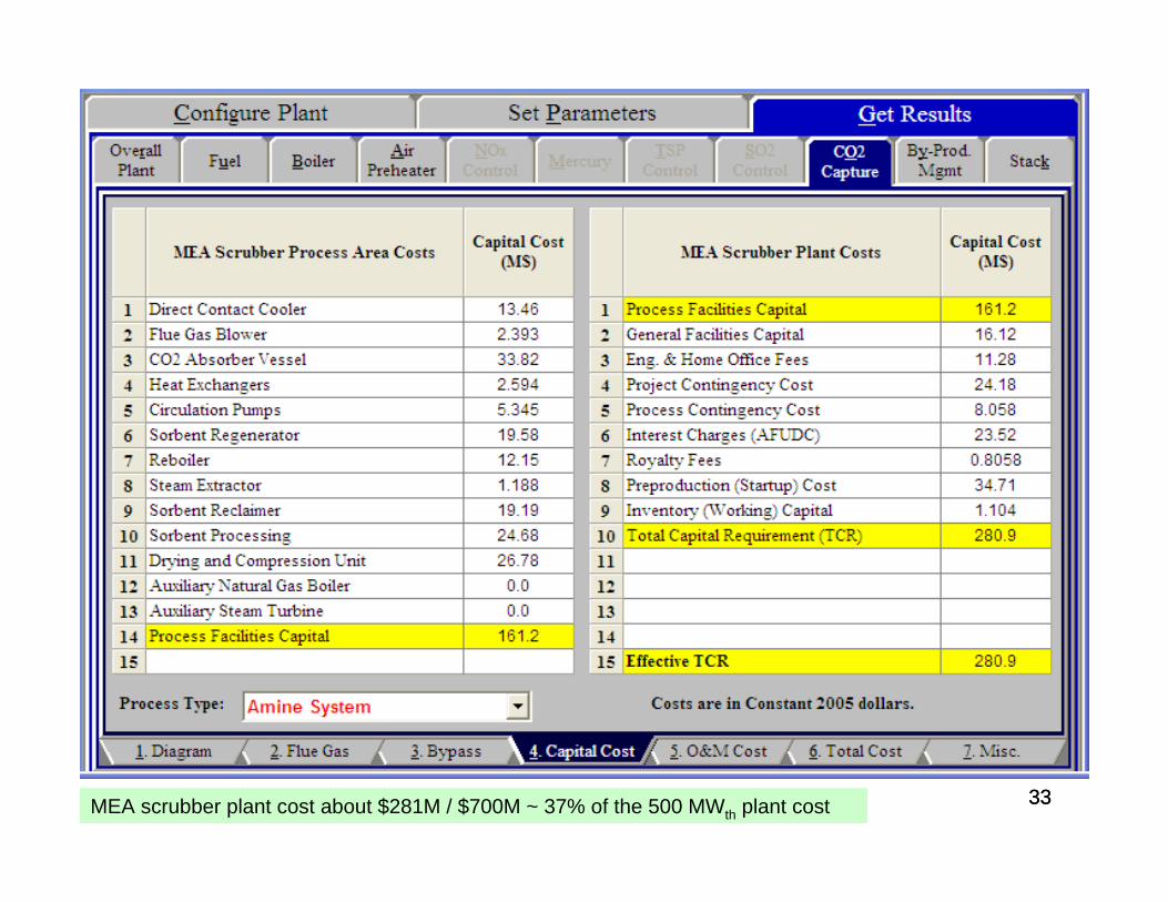
3333MEA scrubber plant cost about $281M / $700M ~ 37% of the 500 MWth plant cost
3434
3535
3636
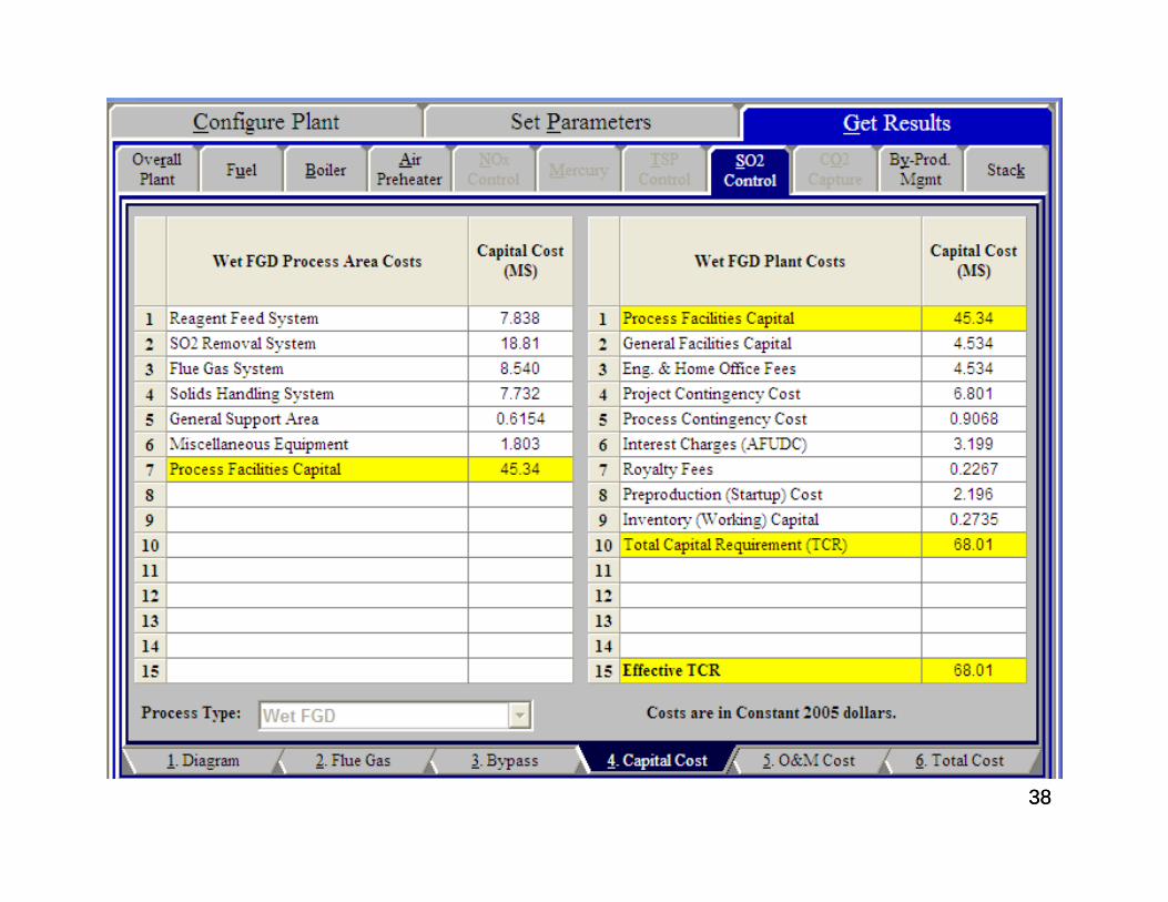
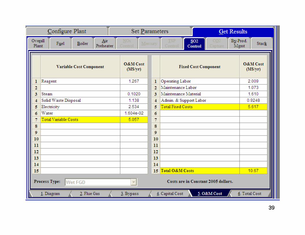
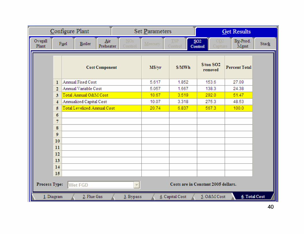
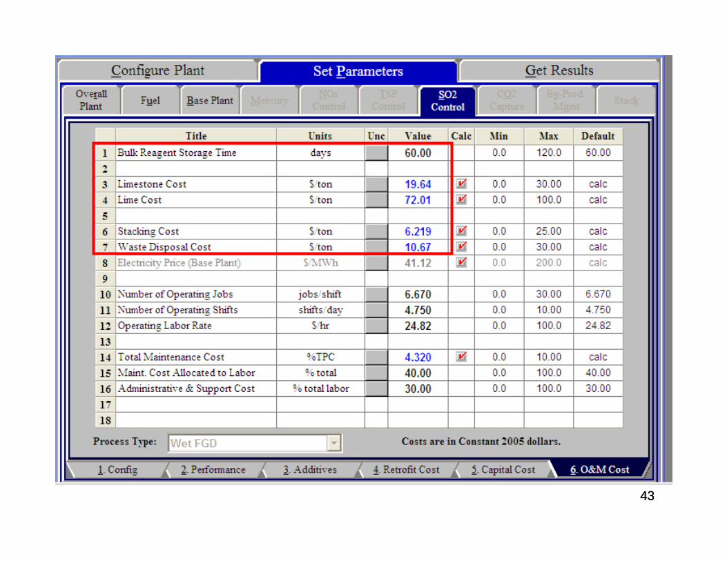
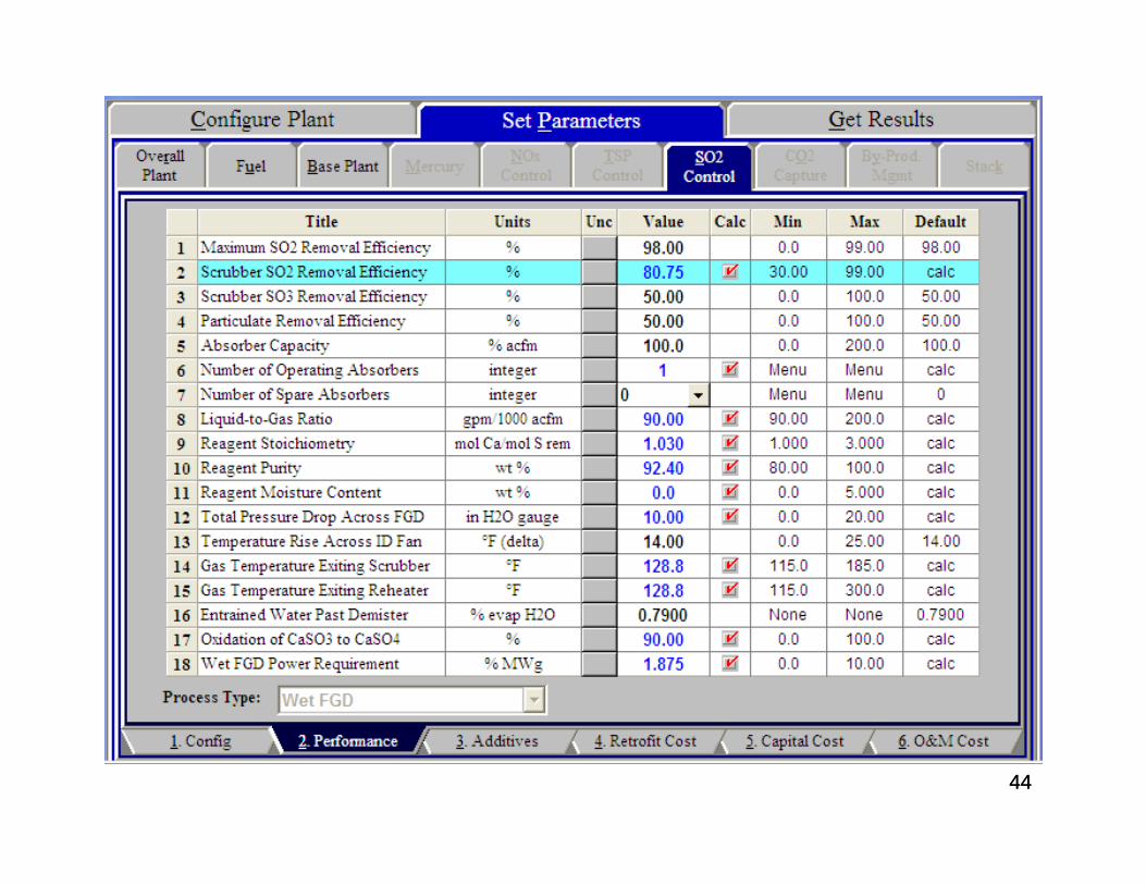
Simulation Results of Wet-FGD Technology for SO2 Removal Using the Integrated Environmental
Control Module (IECM)
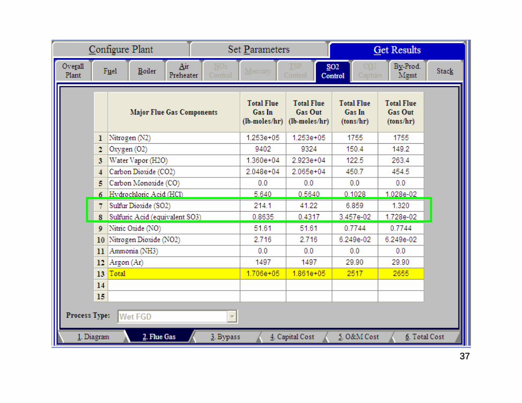
3737
3838
3939
4040
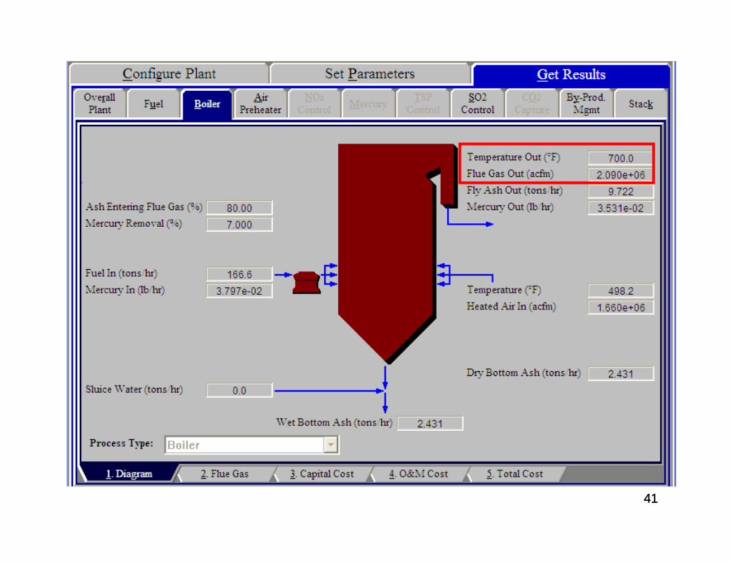
4141
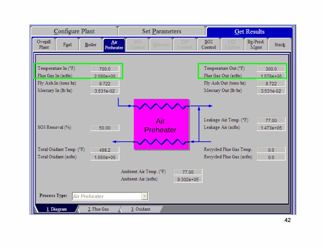
4242
Air Preheater
4343
4444
45
ESP Simulation Results
46
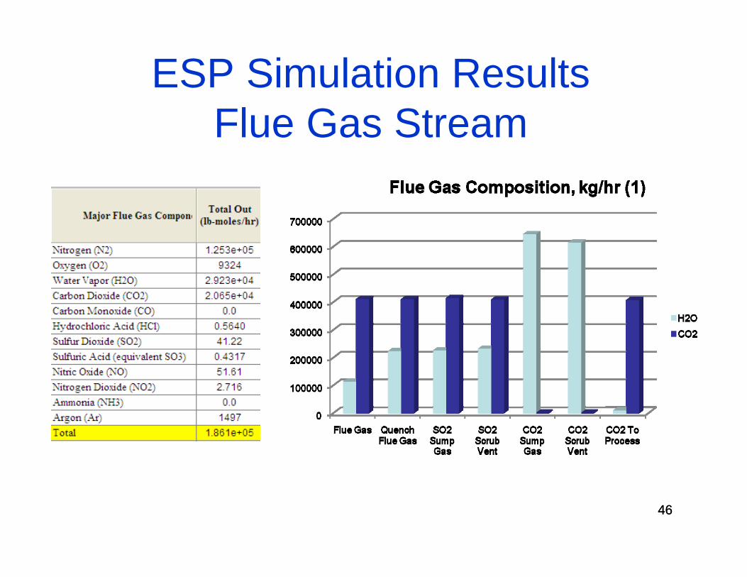
ESP Simulation ResultsFlue Gas Stream
46
47
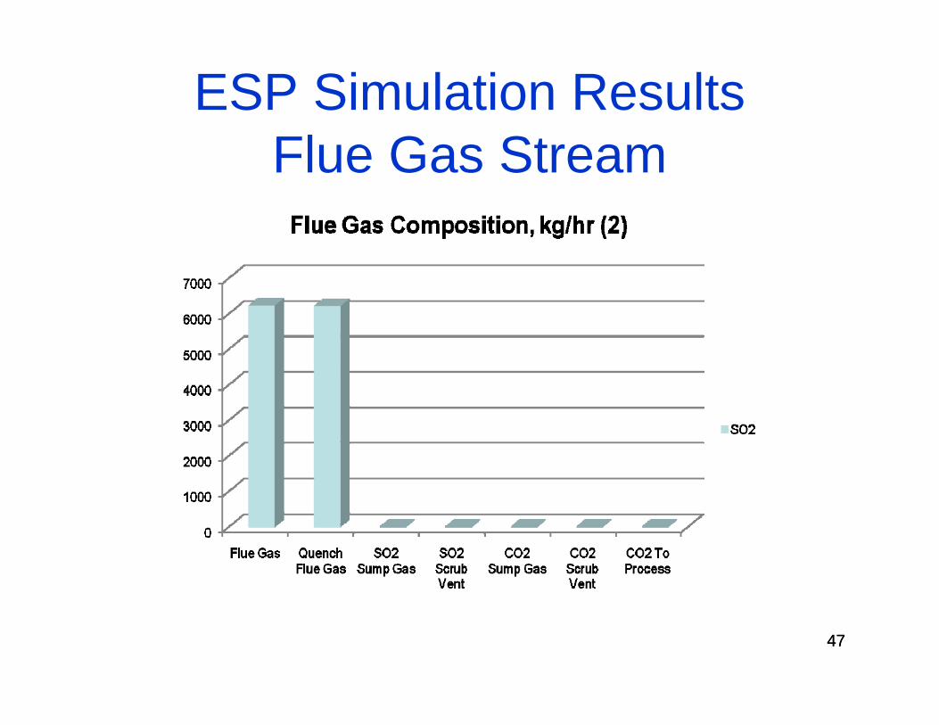
ESP Simulation ResultsFlue Gas Stream
47
48
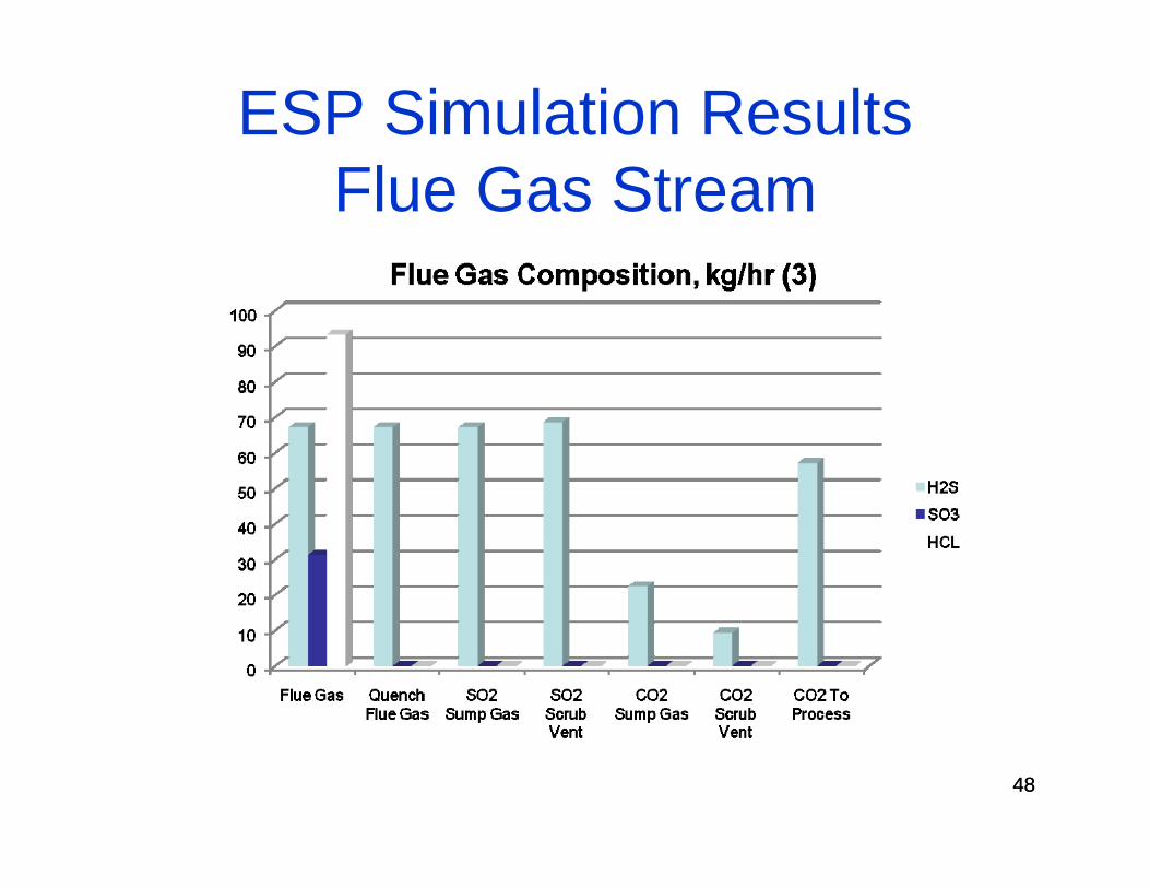
ESP Simulation ResultsFlue Gas Stream
48
49
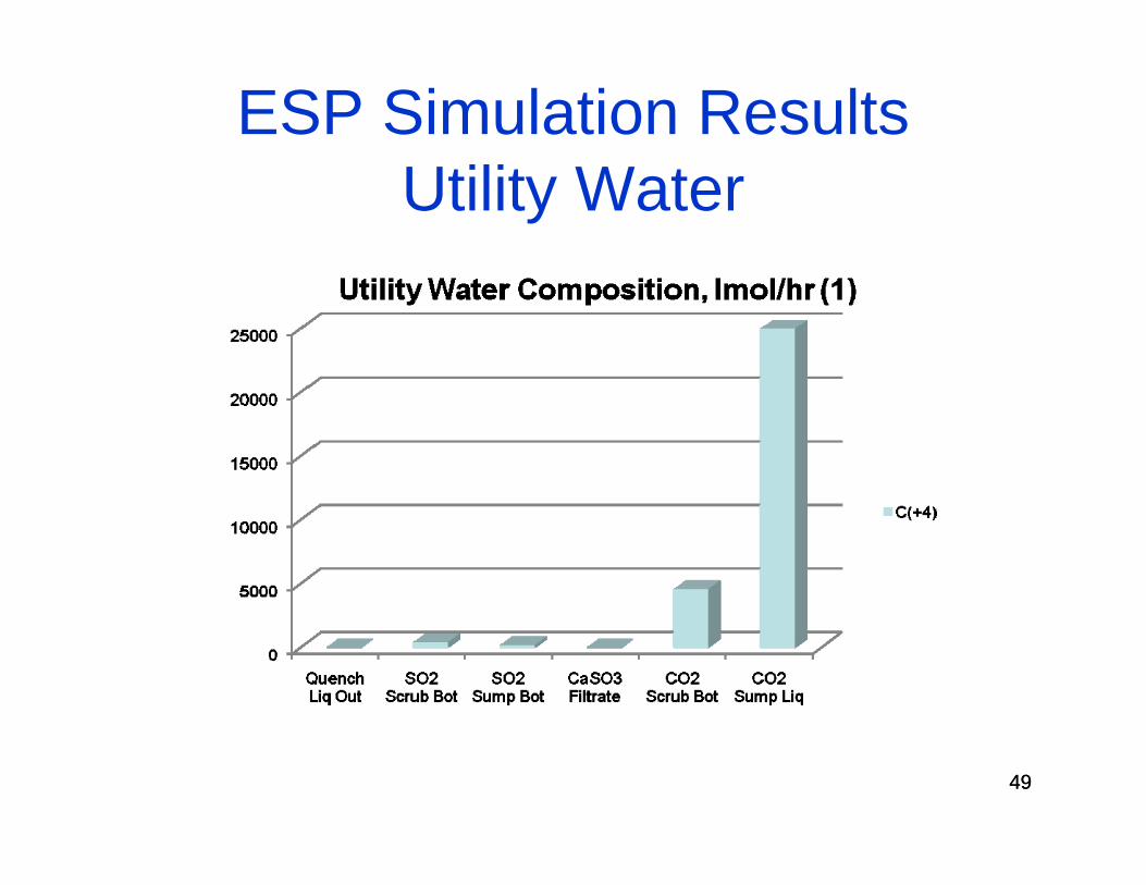
ESP Simulation ResultsUtility Water
49
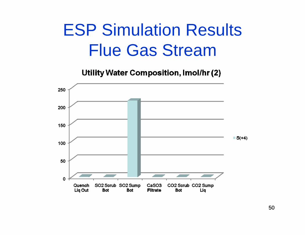
50
ESP Simulation ResultsFlue Gas Stream
50
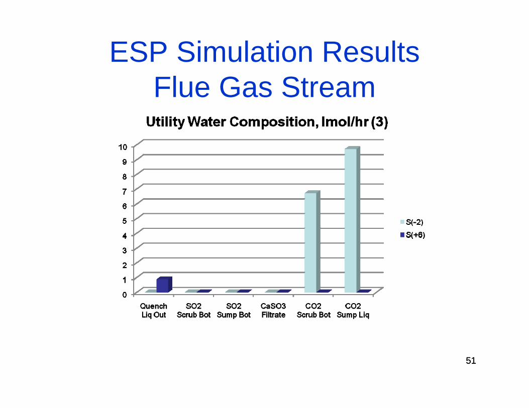
51
ESP Simulation ResultsFlue Gas Stream
51
52
Summary
OLI’s ESP was a useful simulation tool for modeling CO2 and SO2 capture using Ca(OH)2 slurry
Other insights and opportunities for improving the ESP simulation capabilities
53
Roadmap for Future Work
Simulate CO2 capture using the monoethanolamine technology
Compare performance/CO2 capture efficiency and raw materials requirements versus CO2 capture using Ca(OH)2 slurry
Calculate the energy requirements for the Ca(OH)2technology and compare to MEA energy requirements
Demonstrate improved Ca utilization in the proposed technology (i.e., Ca consumed to remove S and C)
Estimate calcium make-up requirements (tons/hr) for the simultaneous removal of CO2 and SO2