Embed Size (px)
Citation preview
Simultaneous Planning, Localization, and
Mapping in a Camera Sensor Network
Ioannis Rekleitis a David Meger b Gregory Dudek b
aCanadian Space Agency, Space Technologies, Saint-Hubert, Quebec Canada 1
bSchool of Computer Science, McGill University, Montreal, Quebec, Canada
Abstract
In this paper we examine issues of localization, exploration, and planning in thecontext of a hybrid robot/camera-network system. We exploit the ubiquity of cameranetworks to use them as a source of localization data. Since the Cartesian position ofthe cameras in most networks is not known accurately, we consider the issue of howto localize such cameras. To solve this hybrid localization problem, we divide it intoa local problem of camera-parameter estimation combined with a global planningand navigation problem. We solve the local camera-calibration problem by usingfiducial markers attached to the robot and by selecting robot trajectories in front ofeach camera that provide good calibration and field-of-view accuracy. We propagateinformation among the cameras and the successive positions of the robot using anExtended Kalman filter. Finally, we move the robot between the camera positionsto explore the network using heuristic exploration strategies. The paper includesexperimental data from an indoor office environment as well as tests on simulateddata sets.
Key words: Sensor Networks, Cooperative Localization.
1 Introduction
In this paper we consider interactions between a mobile robot and an emplacedcamera network. In particular, we would like to use the camera network to ob-serve and localize the robot, while simultaneously using the robot to estimatethe positions of the cameras (see Fig. 1). Notably, networks of surveillancecameras have become very commonplace in most urban environments. Unfor-tunately, the actual positions of the cameras are often known only in the most
Email addresses: [email protected] (Ioannis Rekleitis),[email protected] (David Meger), [email protected] (Gregory Dudek).1 Work done at McGill University.
Preprint accepted at Robotics and Autonomous Systems 17 August 2006
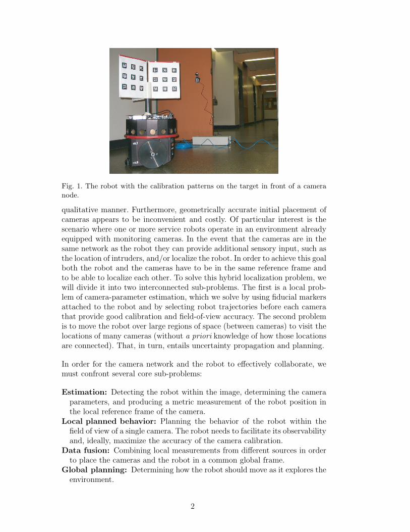
Fig. 1. The robot with the calibration patterns on the target in front of a cameranode.
qualitative manner. Furthermore, geometrically accurate initial placement ofcameras appears to be inconvenient and costly. Of particular interest is thescenario where one or more service robots operate in an environment alreadyequipped with monitoring cameras. In the event that the cameras are in thesame network as the robot they can provide additional sensory input, such asthe location of intruders, and/or localize the robot. In order to achieve this goalboth the robot and the cameras have to be in the same reference frame andto be able to localize each other. To solve this hybrid localization problem, wewill divide it into two interconnected sub-problems. The first is a local prob-lem of camera-parameter estimation, which we solve by using fiducial markersattached to the robot and by selecting robot trajectories before each camerathat provide good calibration and field-of-view accuracy. The second problemis to move the robot over large regions of space (between cameras) to visit thelocations of many cameras (without a priori knowledge of how those locationsare connected). That, in turn, entails uncertainty propagation and planning.
In order for the camera network and the robot to effectively collaborate, wemust confront several core sub-problems:
Estimation: Detecting the robot within the image, determining the cameraparameters, and producing a metric measurement of the robot position inthe local reference frame of the camera.
Local planned behavior: Planning the behavior of the robot within thefield of view of a single camera. The robot needs to facilitate its observabilityand, ideally, maximize the accuracy of the camera calibration.
Data fusion: Combining local measurements from different sources in orderto place the cameras and the robot in a common global frame.
Global planning: Determining how the robot should move as it explores theenvironment.
2

The first two sub-problems (estimation and local planning behaviour) are partof the local problem of camera-parameter estimation, and the last two (datafusion and global planning) are part of the general SLAM problem.
The task of computing camera parameters and obtaining metric measurementsis referred to as camera calibration and is well-studied in both photogramme-try and computer vision [1,2]. Calibration by standard techniques is a hu-man operator intensive process, which is not suited for use by an autonomousrobot. Section 3.1 will detail an automated version where the robot replacesthe human operator in moving the calibration pattern and collecting images.A system of bar-code-like markers (see Fig. 3) is used along with a detec-tion library [3] so that the calibration points are detected robustly, with highaccuracy, and without operator interaction.
Measurements from the calibration process can be used to localize the robotand place each camera within a common reference frame. This mapping prob-lem can be formulated as a standard instance of Simultaneous Localization andMapping (SLAM). Typically the robot uses its sensors to measure the relativelocations of landmarks in the world as it moves. Since the measurements ofthe robot motion as well as those of the relative pose of landmarks are imper-fect, estimating the true locations becomes a filtering problem, which is oftensolved by using an Extended Kalman filter (EKF). Our situation differs fromstandard SLAM in that our sensors are not pre-calibrated to provide metricinformation. That is, camera calibration must be performed as a sub-step ofmapping.
In the framework discussed here, measurements can only be made when thecalibration target is in the field of view of the cameras. Therefore, robot motionplanning is crucial in a number of contexts. During exploration, the order andfrequency at which the robot visits the cameras will greatly affect mappingaccuracy. Several heuristic strategies for this “global exploration problem” aresuggested in Section 5 and are compared experimentally in Section 6.3. Inaddition, the path that the robot follows in front of a single camera duringcalibration will allow a variety of images of the target to be taken. During this“local exploration problem” the set of captured images must provide enoughinformation to recover camera parameters. The calibration literature [4] detailsseveral cases where a set of images of a planar target does not provide sufficientinformation to perform the calibration. The robot must clearly avoid any suchsituation, but we can hope for more than just this simple guarantee. Throughanalysis of the calibration equations, and the use of the robot odometry, thesystem discussed here has the potential to perform the calibration optimallyand verify the results.
The following section discusses related research. Section 3 details camera cal-ibration using marker detection and a 6 degree of freedom (DOF) EKF for
3

mapping in our context. Section 4 continues the discussion of local calibrationpaths. The heuristics for exploring the sensor network are discussed in Section5. Section 6 provides experimental results to examine the effect of different lo-cal and global paths and shows the system operating in an office environmentof 50 m in diameter. We finish this paper with concluding remarks.
2 Related Work
Previous work on the use of camera networks for the detection of moving ob-jects has often focused on person tracking in which case the detection andtracking problem is much more difficult than that of our scenario (due to lackof cooperative targets and a controllable robot) [5–9]. In general, camera-based tracking for either surveillance or activity estimation presupposes thatcamera positions are either unknown or unnecessary. Inference of camera net-work topology from moving targets has been considered [8,10]. These methodsemploy probabilistic inference techniques to find the most likely connectionsbetween nodes based on observations. Like our method, they produce a mapof the network. Ellis et al. depend on cameras with overlapping fields of view.Marinakis et al. deal with non-overlapping cameras, but only topological in-formation is inferred here while we are interested in producing a metric mapof the cameras. Batalin and Sukhatme [11] used the radio signals from nodesin a sensor network for robot localization. The spirit of this system is quitesimilar to our own, but the use of cameras instead of radio signal strengthpresents us with a large number of new challenges and several advantages.Moreover, the previous work considered only localization, while our systemalso maps the camera poses. Cooperative localization of multiple robots hasbeen considered by many authors, e.g., [12–15], where instead of stationarycamera nodes a moving robot is observed by other robots.
Camera calibration is a very well studied problem; a good summary paperby Tsai [16] outlines much of the previous work, and authors such as Zhang[4] and Faugeras [17] present improvements made, more recently. A series ofpapers by Tsai et al. [18,19] use a 3-D target and a camera mounted on theend of a manipulator to calibrate the manipulator as well as the camera. Afairly complete study of calibration error as a function of properties of a cali-bration image set is provided, which gives intuition for our local path planningproblem. Heuristics are provided to guide the selection of calibration imagesthat minimizes that error [18]. However, these methods only deal with a sin-gle camera and use manipulators with accurate joint encoders, i.e., odometryerror is not a factor. In the mobile robot context, the presence of large-scaleodometry error makes the problem much more challenging.
One important step in the automation of camera calibration is the accurate
4

(a) (b)
Fig. 2. (a) An example ARTag marker. (b) A calibration target formed from ARTagmarkers.
detection of the calibration pattern in a larger scene. Fiducial markers areengineered targets that can be detected easily by a computer vision algorithm.ARToolkit [20] and ARTag [3] are two common examples of fiducial markers.ARTag markers are square black and white patches with a relatively thicksolid outer boundary and an internal 6 by 6 grid (see Fig. 2(a)). The outerborder is used for quad detection and the internal grid uniquely identifies eachmarker even under arbitrary rotation and reflection. The advantages of thissystem are reliable marker detection with low rates of false positive detectionand marker confusion. ARTag markers have been previously used for robotlocalization where a camera viewed robots from above, each of which had onemarker attached to its top [21]. Our system extends this concept to allowmultiple cameras in general position.
The EKF is used for mapping in the presence of odometry error [22,23], amethod that began the now very mature SLAM field. An example of previoususe of camera networks for SLAM is Rekleits and Dudek [24]. Our work ex-tends this previous method by using ARTag markers for much more automateddetection of calibration target points, performing SLAM with 3-D position andorientation for cameras and examining both local and global planning. Thisgives our system a higher level of autonomy and allows mapping of much largerenvironments.
In this work, we calibrate the entire camera network by covering the envi-ronment using an exploration-like strategy (since we do not presuppose a geo-metric map in correspondence with the camera layout). Exploring this cameranetwork is related to work in both coverage and exploration. In the case of agraph-like environment, as pioneered by Kuipers [25], various techniques havebeen proposed often assuming that minimal information is available [26–28].
The exploration problem has been addressed by a variety of researchers. Someprior works put the emphasis on the completeness of the exploration [29,30].An alternative approach emphasizes exploration while minimizing uncertainty[31]. Yet another class of approaches seeks to optimize both accuracy and
5
efficiency [32] keeping in mind the trade-off between the two. The presentwork relates to all three, although the latter is the closest in spirit to ourobjectives.
3 Mapping and Calibration Methods
Our approach to the general problem of mapping a camera sensor network isdivided into two sub-problems: acting locally to enhance the intrinsic param-eter estimation; and moving globally to ensure coverage of the network whilemaintaining good accuracy. The robot will move between camera locations toaccomplish its long term objectives. As it visits each location for the first time,the robot is detected by a camera. Thus, it can exploit its model of its ownpose and the relative position of the camera to the robot to estimate the cam-era position. In order to recover the coordinate system transformation betweenthe robot and the camera, it is necessary to recover the intrinsic parametersof the camera through a calibration procedure. This process can be facilitatedby appropriate local actions of the robot. Finally, over the camera network asa whole, the robot pose and the camera pose estimates are propagated andmaintained using a Kalman filter and a heuristic planner.
A target constructed from 6 grids of ARTag markers is used for automateddetection and calibration. When the robot moves in front of a camera, themarkers are detected, and the corner positions of the markers are determined.A set of images is collected for each camera, and the corner information isused to calibrate the camera. Once a camera is calibrated, each subsequentdetection of the robot results in a relative camera pose measurement. Thefollowing sub sections provide details about the steps of this process.
3.1 Automated Camera Calibration
A fully automated system is presented for the three tasks involved in cameracalibration: collecting a set of images of a calibration target; detecting pointsin the images which correspond to known 3-D locations in the target referenceframe; and performing calibration, which solves for the camera parametersthrough nonlinear optimization. The key to this process is the calibrationtarget mounted atop a mobile robot as shown in Fig. 1. The markers on thepanel are easily and robustly detected, so that the system can immediately beaware each time the robot passes in front of a camera. The robot can then moveslightly, so that different views of the calibration targets are obtained until asufficient number is available for calibration. Each planar panel comprisesnine square ARTag markers (four corners each), thus providing 36 calibration
6

(a) (b)
Fig. 3. (a) The calibration target is formed by 3 panels and mounted on top of therobot. (b) A top view of the target. The x and y axes of the robot coordinate frameare displayed as thick solid arrow lines and the x (or y) and z axes of each of the sixgrid coordinate frames are displayed as dashed arrow lines; solid thin lines representthe outline of the target.
points in an evenly spaced planar grid. Six panels are mounted on the front andthe back sides of three vertical metal planes. The three planes are separatedby 100, 120, and 140 degrees. The 3-D locations of each marker corner in therobot frame can be determined through simple measurements, and the ARTagsoftware library provides robust detection of these corner points in the image.
The ARTag system requires that each marker occupies a sufficient portion ofthe image for the relatively fine details of the internal six by six grid to beidentified. This imposes a limit of approximately 15 pixels as the minimummarker size in the image for robust detection, which translates into a maximumdistance from the camera at which the calibration panel can be identified.The specific distance depends on camera resolution and imaging propertiesas well as the size of the target. With inexpensive cameras and a letter-sizedpaper target, approximately a 2 m maximum detection distance is achieved.Of course higher-resolution camera hardware and larger calibration patternswill increase this distance.
The nonlinear optimization procedure used for camera calibration [4] warrantsa brief discussion. A camera is a projective device, mapping information aboutthe 3-D world onto a 2-D image plane. A point in the world M = [X, Y, Z, 1]T
is mapped to pixel m = [u, v, 1]T in the image, under the following equation:
7

s
u
v
1
︸ ︷︷ ︸
m
=
fx α ux
0 fy uy
0 0 1
︸ ︷︷ ︸
A
[
R t
]
︸ ︷︷ ︸
T
X
Y
Z
1
︸ ︷︷ ︸
M
(1)
where s is the arbitrary scale factor of the projective equation. In matrixA, fx and fy represent the focal lengths in pixel related coordinates, α isa skew parameter, and ux and uy are the coordinates of the center of theimage. Collectively, these are referred to as intrinsic camera parameters. TheT matrix is a homogeneous transformation made up of a 3×3 rotation matrixR and translation vector t of length 3, and it expresses the position and theorientation of the camera with respect to the calibration-target coordinateframe. The elements of T are referred to as extrinsic parameters and changeevery time the camera or the calibration target moves to describe the relativeposition of the calibration target to the camera. We will use the T matrix asa measurement in the global mapping process described in detail in Section3.2.
The calibration images give a number of correspondences (u, v) → (X, Y, Z),which are related by (1). This relation allows the intrinsic camera parametersand the extrinsic parameters of each image to be jointly estimated using atwo-step process. The first step is a linear solution to find the most likelyintrinsic parameters. The second step is a nonlinear optimization which in-cludes polynomial distortion parameters. It will be important for our furtherdiscussion to mention what Zhang [4] calls “degenerate configurations” whereadditional views of the calibration target do not provide additional informa-tion for calibration. The strongest result given is that any two calibrationplanes which are parallel to each other do not provide sufficient informationfor calibration. The intuition here is that the rotation matrix R is used toproduce constraints on the intrinsic parameters; as the rotation matrices forparallel planes are linearly dependent, they produce an under-constrained sys-tem. To avoid this situation, several different local motion strategies, used toobtain an adequate set of images, are discussed in Section 4.
In conclusion, detecting a set of images of the robot-mounted target and thendetecting the grid pattern from the corners of the ARTag markers provideenough information to extract the camera intrinsic parameters and then calcu-late the extrinsic parameters. The extrinsic parameters of the camera providean estimate of the camera pose relative to the robot. The next section willdiscuss the use of an Extended Kalman filter to combine these estimates withrobot odometry in order to build a map of camera positions.
8
(a) (b)
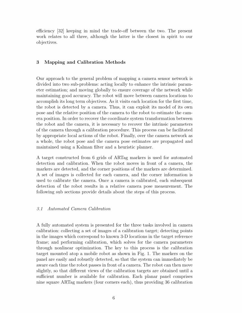
Fig. 4. (a) Measurement Coordinate Frame Transformations. (b) Coordinate framesfor the world (origin at [0,0,0]), robot (denoted by a circle and a line for the ori-entation), target grid (dashed lines G2,G3) and camera (solid lines C1,C2). Thetrajectory of the robot is marked by a dotted line.
3.2 Six-DOF EKF
The previous section described a method for obtaining an estimate of the cam-era position relative to the robot through the extrinsic parameter matrix T .These measurements can be used to build a consistent global map by addingthe camera position to the map when initial calibration finishes and by im-proving the estimate each time the robot returns to the camera. To maintainconsistent estimates in this global mapping problem, an Extended Kalmanfilter is used to combine noisy camera measurements and odometry in a prin-cipled fashion. The robot pose is modeled as position and orientation on theplane: (x, y, θ). However, the cameras may be positioned arbitrarily; so, their3-D position and orientation must be estimated. Roll, pitch, and yaw anglesare used to describe orientation, thus the state of each camera pose is a vectorXc = [x, y, z, α, β, γ]T . For a complete discussion of angle representations, see[33].
The EKF tracks the states of the robot and the cameras in two steps: thepropagation step tracks the robot pose during motion, and the update stepcorrects the robot and the camera poses based on the measurements fromthe calibration process. Since only the robot moves during the propagationphase, the equations are identical to those used in previous work [22]. Thestate vector and the covariance matrix are updated as:
Xk|k−1 =FXk−1|k−1 (2)
9
Pk|k−1 =FPk−1|k−1FT + Cu (3)
where F obtained by linearizing the nonlinear propagation function f(X, u)where u are control actions, and Cu is a matrix representing odometry error.For the update phase, the measurement equation is a nonlinear expression ofthe state variables so we must again linearize before using the Kalman filterupdate equations. The measurement equation relates two coordinate frames,so that the language of homogeneous coordinates transformations is used inorder to express the relation. In general, any two coordinate frames are relatedby a transformation matrix as follows [33]:
baT =
baR
bPaorig
01x3 1
(4)
In this case, the transformation expresses frame a in coordinates of frame b.baR is the 3 × 3 rotation matrix which represents the orientation of a as seenin b. bPaorig
gives the translation of the origin of frame a in coordinates offrame b. Going back and forth between transformation T and roll, pitch, andyaw angles in state vector X is a simple process [33]. The EKF will only dealwith state vectors, but the transformation matrices are used in the followingto derive the measurement equations.
The measurement update equation is derived below. The calibration processestimates the extrinsic parameters which represent the calibration panel in thecamera frame, that is C
P T . Since the panels are rigidly attached to the robot, thetransformation between the two, namely P
RT , is easily measured and treatedas a constant throughout the procedure. When a new measurement arrives, itcan immediately be used to relate the camera and the robot coordinates byCRT =C
P T PR T . This is the measurement z. Next, the measurement is expressed
in terms of the filter states Xr and Xc. As mentioned, these state vectorsare used to get the transformations for the robot and the camera in worldcoordinates: W
R T and WC T . Fig. 4 illustrates the relationships between the EKF
state variables and the information obtained from camera calibration whichjointly form the measurement equation:
zmeasured = CRT = C
WTWR T = W
C T−1WR T =
WC RT
−WC RT W
C P
0 1
WR R W
R P
0 1
=
WC RT W
R R WC RT (W
R P −WC P )
0 1
(5)
10
(a)
Rotation
(b) (c)
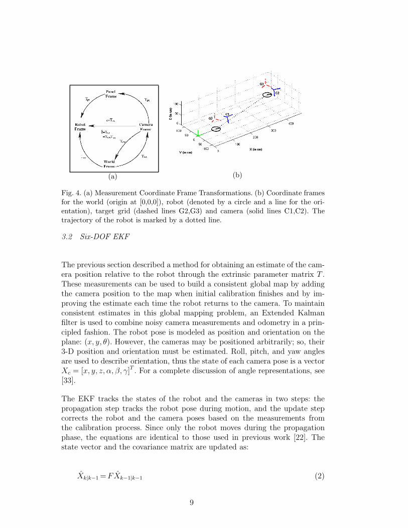
Fig. 5. Sample trajectories for local calibration: (a) translation; (b) rotation, (c)square.
Equation 5 provides the measurement equation z = h(X). To use this in aKalman filter, we must differentiate h with respect to each parameter to obtaina first-order linear approximation z = h(X)+HX where H is the Jacobian ofvector function h. Measurement noise Cω expresses the uncertainty of trans-formation parameters from camera calibration. The EKF update equationscan be applied as usual:
Xk|k = Xk|k−1 + K(z − h(Xk|k−1)) (6)
Pk|k =[
I − KHT]
Pk|k−1 (7)
K = Pk|k−1H(HPk|k−1HT + Cω)−1 (8)
4 Local Calibration Procedures
Using a robot-mounted target provides a unique opportunity to collect calibra-tion images in an intelligent fashion by controlling the robot motion. However,it is not immediately clear what the best motion strategy will be. There are nu-merous sources of error including detecting the original pixels, approximatingthe linear parameters, and convergence of the nonlinear optimization. Ideally,the robot should move in such a way that the resulting image set reduces thecombined effect of all these error sources and gives the most accurate calibra-tion possible. There are several sources of information on how to approach thistask. As mentioned previously, Zhang [4] showed that it is essential to avoidhaving only parallel planes and Tsai [18] discussed heuristics for obtaining im-ages to calibrate a manipulator system. These heuristics included having thecamera lens center near the calibration block, and maximizing the rotation an-gle between subsequent images. In addition to the calibration error reduction,the accumulated odometric error is another important factor for the overallaccuracy of the system as it increases the uncertainty of our EKF estimate. As
11
such, schemes that require excessive robot motion to achieve good calibrationshould be avoided.
As an initial investigation into this problem, five motion strategies were ex-amined. These were chosen to cover the full spectrum of expected calibrationaccuracy and odometry error buildup:
Stationary: The robot moves in front of the camera and stays in one spot.Due to the target geometry, this allows for two non-parallel panels to beobserved by the camera, which provides the minimal amount of informationnecessary for calibration.
One Panel Translation-only: The robot translates across the camera fieldof view (FOV) with only a single calibration panel visible always at thesame angle. This is a degenerate case and did not produce good calibration.
Multi-Panel Translation-only: The robot translates across the camera FOVwith two calibration panels visible. This provides two non-parallel planes forcalibration and accumulates a minimal amount of odometry error (see Fig.5a).
Rotation-only: The robot rotates in place in the center of the camera FOVallowing the panels to be detected at a variety of angles (see Fig. 5b).
Square Pattern: The robot follows a square-shaped path in front of thecamera, alternating translation and rotation by 90 degrees. This forms asquare with 4 corners. At each corner, the robot has two poses with per-pendicular orientation. Since a large portion of the image is covered andthere is variation in the detected panel orientation and depth, this methodachieved good calibration accuracy. However, the combination of rotationand translation caused large odometry error (see Fig. 5c).
5 Global Exploratory Trajectories
While performing the mapping process described in Section 3, the robot has apartially constructed map, and must travel into previously unvisited territoryin order to add new cameras to this map. If the robot were to continually moveinto unexplored regions, it would be able to cover its environment quicklyat the cost of accumulating a large amount of uncorrected odometry error.The robot can slow this error buildup by periodically returning to regions ofthe map that have already been visited, so its position can be corrected bycamera measurements. This behavior will be referred to as “relocalizing”. Thisrelocalization behavior will allow for mapping with lower uncertainty, but willrequire the robot to travel farther in order to cover the space. This describes atrade-off which will be present in any exploration system; covering the spacewith small distance traveled and mapping with low uncertainty are conflictinggoals.
12
(a) (b)
(c) (d)
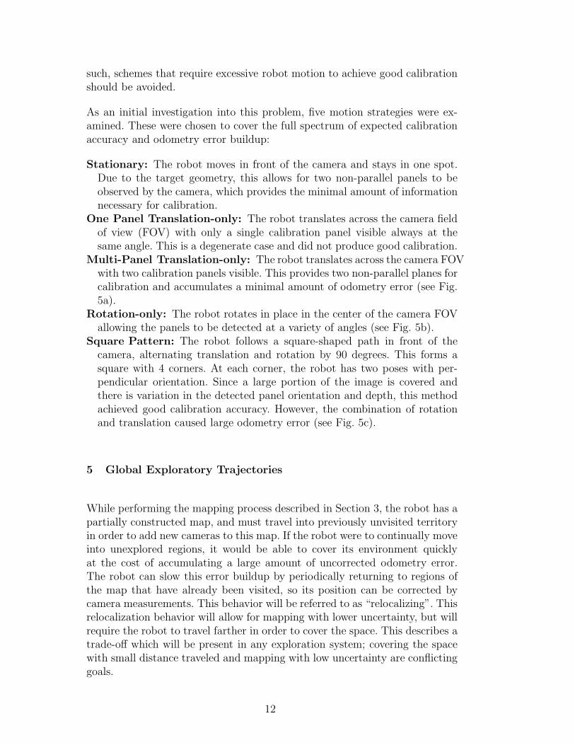
Fig. 6. The progress of the Return-to-nearest exploration strategy while exploringa random graph is shown at 4 intermediate steps progressing left to right and topto bottom. The arrow points to the last node visited by the robot.
In view of the distance and uncertainty trade-off, we consider several specificstatic policies that typify the behavioral extremes with respect to which mostother mechanisms can be described.
Depth-first: The robot always moves into unexplored territory, never relo-calizing. This strategy provides coverage of the environment with minimaldistance traveled, but the uncertainty of the robot position grows quickly.
Return-to-Nearest: The robot alternates between exploring a new cameraposition and relocalizing at the nearest previously explored camera. Forexample, Fig. 6 shows several stages of the exploration process. The abilityto relocalize accurately depends on the uncertainty of the nearest cameraonly, which might not be mapped as accurately as cameras which are fartherfrom the robot. However, only regressing by one camera at a time meansthe extra distance traveled is minimal.
Return-to-Origin: The robot alternates between exploring a new cameraposition and returning to the first camera it mapped, which has the lowestuncertainty. This strategy allows extremely good relocalization, but means
13

the robot must travel a large distance between each newly explored camera.
These three strategies do not capture the full range of possibilities, and theyprovide neither flexibility nor adaptation to the environment. However, theyare presented as an initial study of the effects of different strategies on theresulting maps and the robot’s ability to navigate in the environment oncemapping is completed. Developing adaptive strategies which provide a param-eter to weigh the effects of distance traveled and uncertainty in mapping isa topic worthy of future work. Section 6.3 presents comparison of the threesimple algorithms presented here.
6 Experimental Results
Three separate sets of experiments were conducted using the camera sensornetwork (see [24] for a detailed description of the experimental setup) whichdealt with the mapping, calibration and planning aspects of our system. First,to show that mapping is feasible in a real-world environment, a robot equippedwith the calibration target moved through one floor of an office building whichwas over 50 m in diameter. We show that the robot path estimate is improvedthrough the use of position measurements from a set of cameras present inthe environment. Second, five different local motion strategies were examinedwith respect to the resulting intrinsic parameters and the position accuracy.Finally, a series of simulated environments was used to examine the effect ofglobal planning strategies. For all simulated results, we used odometric noisevalues determined experimentally in our laboratory [34].
6.1 Mapping an Office Building
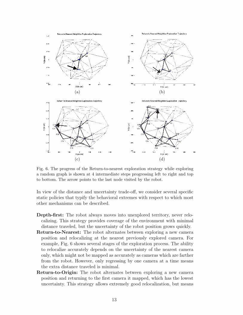
To demonstrate the effectiveness of the system when mapping a large space,we instrumented an office environment with 7 camera nodes. The environmentconsisted of a rectangular loop and a triangular loop connected by a hallwaywith length approximately 50 m. A Nomadics Scout robot mounted with atarget with six calibration patterns was used to perform the calibration andmapping procedure described in Section 3. The robot traversed the two loopsof the environment 3 times and traveled in excess of 360 m in total. TheRotation-only local calibration strategy described in Section 4 was used forsimplicity. In these tests 30 images were collected for calibration, which tookless than 1 minute per camera node to collect. The OpenCV computer visionlibrary was used for camera calibration [35]. Fig. 7a,b show the odometry pathestimate and the path corrected by observations from the cameras.
14
−1000 −500 0 500 1000 1500 2000 2500 3000
−1500
−1000
−500
0
500
1000
1500
X(cm)
)m
c(Y
Odometry Readings
(a)
−1000 −500 0 500 1000 1500 2000 2500 3000
−1500
−1000
−500
0
500
1000
1500
X(cm)
)mc
(Y
EKF Estimated Path and Camera Positions
(b)
Fig. 7. (a) Odometry Readings for Hallway Path. (b) EKF Estimate of the HallwayPath. Estimated camera positions with uncertainty ellipses (in red where colour isavailable).
It is visually clear (Fig. 7a,b) that the use of camera measurements was ableto correct for the buildup of odometry error relatively well. However, thereare some regions where the filtered path is still a very rough approximationdue to large distances between cameras. These distances are traveled withoutcorrection of the odometry error. This is most obvious on the far right of theimage during the 3rd loop where there is a very noticeable discontinuity inthe filtered path as the large odometry error is corrected by a camera mea-surement. Since the current system does not provide a means for odometrycorrection between the camera fields of view, this type of result is unavoid-able where large odometry errors occur. Solutions include placing the camerasmuch closer together to limit the size of the unobservable regions, performingSLAM with another sensor such as sonar or laser to provide a complementaryapproach, or adopting a smoothing technique. We will leave further discussionof these possibilities for the conclusions.
No ground truth data was collected for this experiment due to lack of availableaccurate measuring devices over this size of environment. In previous work,in a similar experiment over a 15 m environment, the camera positions werefound to deviate from the true positions by 2.11 cm on average with standarddeviation 1.08 cm [34].
6.2 Local Calibration Paths
A second set of experiments was performed to test the effects of the localcalibration paths suggested in Section 4. The goal was to study the motionstrategies in terms of reliable camera calibration as well as magnitude of odom-etry error. This test was done inside our laboratory with the same robot andcalibration panel as the previous experiment but using only a single camera.
15

The 5 strategies were performed for 10 trials, each with n = 30 calibrationpanels detected per trial. The automated detection and calibration systemallowed for these 50 trials and 1500 pattern detections to occur in under 3hours (using a Pentium IV 3.2 GHz CPU running linux for both image anddata processing).
Table 1Mean Value and percentage of Standard Deviation of the Intrinsic Parameters foreach strategy over 10 trials. One Panel Translation-only is omitted due to divergence.Deviations are with respect to the mean, ground truth error is not provided.
Path Mean Values Standard Deviation (%)
fx fy ux uy fx fy ux uy
Stationary 903.2 856.0 233.5 190.6 6.3 5.6 30.9 17.1
Translation 785.8 784.3 358.0 206.4 2.7 2.3 3.6 5.0
Rotation 787.7 792.0 324.1 236.6 1.6 1.6 3.9 10.3
Square 781.2 793.1 321.4 274.2 1.2 2.0 2.4 13.9
(a)
0 5 10 15 20 25 30 35 40 45 500
1
2
3
4
5
6
7
Step
ec
nair
av
oC f
o e
car
T
Trace of Covariance vs Step in Path
Translation
Rotation
Square
(b)
Fig. 8. (a) Sample Images from Square Pattern. (b) Odometry Error Accumulationfor 3 Local Calibration Paths
Table 1 summarizes the intrinsic parameters obtained for each method. Thelack of data for the One Panel Translation-only path is due to that, as ex-pected, calibration diverged quite badly in all trials with this method. Otherthan the stationary method, for all the other strategies, the mean parameterestimates are not statistically significantly different.
To examine the difference between odometry buildup among the differentpaths, each of the three paths which involved motion was simulated usingan EKF (the stationary approach clearly does not build any odometry error).To ensure a fair comparison, the step size in the Translation-only method wasset equal to the side length of the square pattern (8 cm each) and the anglestep in the Rotation-only method was set to 90 degrees. This meant that thesquare pattern translated half of the distance of Translation-only and rotated
16

−3000 −2000 −1000 0 1000 2000 3000−3000
−2000
−1000
0
1000
2000
3000
X (in cm)
Return−to−Origin Exploration
)m
c ni(
Y
(a)
−3000 −2000 −1000 0 1000 2000 3000−3000
−2000
−1000
0
1000
2000
3000
X (in cm)
Return−to−Nearest Exploration
)m
c ni(
Y
(b)
Fig. 9. Camera uncertainty ellipses after mapping completed using strategy: (a)Return-to-Origin and (b) Return-to-Nearest
half the angle of Rotation-only. Fig. 8(b) shows the trace of the covariance ma-trix as each method progresses. The square pattern accumulates much moreodometry error than the other two methods, as expected. We must note thatthe relative slopes in this figure are influenced by the choice of odometry errorcovariances in the EKF, but that realistic values established through previousexperimentation were used [34].
6.3 Exploration Trajectories
The heuristic exploration trajectories discussed in Section 5 were examinedin simulation to compare their effect on uncertainty buildup and distancetraveled. Two different classes of simulated environments were chosen. Thefirst was the class of uniform planar graphs with a dense set of edges, producedby triangulation. This type of environment allowed for ease in creation ofvarious sizes of environment and densities of cameras. The second environmentwas based on a sample floor-plan image of a hospital environment obtainedas part of the Player/Stage system [36]. In this environment the walls andobstacles prevent the formation of a dense set of edges, and paths betweencameras must be much less direct.
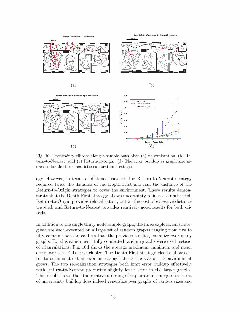
On the first environment, the uniform graphs, each exploration trajectorywas performed on the same thirty node instance to provide direct compari-son. Figure 9 shows final 3σ camera uncertainty ellipses after exploration hascompleted for both of the relocalization strategies presented, but does not in-clude the Depth-first strategy since the final uncertainty was over twelve timesgreater than the other strategies. Table 2 summarizes the numerical resultsfor all 3 strategies in terms of area of uncertainty and distance traveled. TheReturn-to-Nearest strategy produced approximately twenty five percent lessarea of uncertainty at the end of exploration than the Return-to-Origin strat-
17
Sample Path Without Prior Mapping
250cm
(a)
Sample Path After Return−to−Nearest Exploration
250cm
(b)
Sample Path After Return−to−Origin Exploration
250cm
(c) (d)
Fig. 10. Uncertainty ellipses along a sample path after (a) no exploration, (b) Re-turn-to-Nearest, and (c) Return-to-origin. (d) The error buildup as graph size in-creases for the three heuristic exploration strategies.
egy. However, in terms of distance traveled, the Return-to-Nearest strategyrequired twice the distance of the Depth-First and half the distance of theReturn-to-Origin strategies to cover the environment. These results demon-strate that the Depth-First strategy allows uncertainty to increase unchecked,Return-to-Origin provides relocalization, but at the cost of excessive distancetraveled, and Return-to-Nearest provides relatively good results for both cri-teria.
In addition to the single thirty node sample graph, the three exploration strate-gies were each executed on a large set of random graphs ranging from five tofifty camera nodes to confirm that the previous results generalize over manygraphs. For this experiment, fully connected random graphs were used insteadof triangulations. Fig. 10d shows the average maximum, minimum and meanerror over ten trials for each size. The Depth-First strategy clearly allows er-ror to accumulate at an ever increasing rate as the size of the environmentgrows. The two relocalization strategies both limit error buildup effectively,with Return-to-Nearest producing slightly lower error in the larger graphs.This result shows that the relative ordering of exploration strategies in termsof uncertainty buildup does indeed generalize over graphs of various sizes and
18

Table 2The accumulated uncertainty and the total distance traveled for the three explo-ration strategies applied to two environments.
Hospital Hospital Hospital Random Random Random
Origin Nearest Depth 1st Origin Nearest Depth 1st
3 σ (cm2) 0.524 0.482 6.065 0.209 0.114 3.05
Dist.(m) 2125 322 115 1210 578 243
densities. The three exploration strategies were performed again in the hos-pital environment. The ability of the maps to aid navigation was evaluatedbased on an example path of length of approximately 18 m. Table 2 summa-rizes the numerical results and shows the same relative ordering in terms ofuncertainty and distance as for the random graph. Fig. 10 shows the samepath executed three times: once for each of the two strategies involving relo-calization and once in a previously unexplored network. The uncertainty atthe end of the path for the Return-to-Origin strategy was slightly larger thanthe Return-to-Nearest despite the fact that the robot traveled over six timesas far during exploration. This suggests the extreme buildup in distance trav-eled for the Return-to-Origin strategy as the size of the environment growsdoes not produce significant corresponding gain in accuracy. One reason forthis effect is likely that nearby landmarks in an EKF have much more effecton each other than those which are far apart. This means that relocalizingvery accurately at the origin is not able to improve the estimation accuracyat distant cameras.
7 Conclusion
We have outlined an automated method for calibrating and mapping a sen-sor network of cameras such that the system can be used for accurate robotnavigation. The experimental methods show that a system with a very simplelevel of autonomy can succeed in mapping the environment relatively accu-rately. A preliminary study was done on local calibration trajectories, whichcan have a profound effect on the accuracy of the mapping system. Furtherwork in planning and autonomy will likely be the key enhancement in furtheriterations of this system. The reliance on detection of the calibration targetmeans the robot must move intelligently in order to produce a map of theenvironment and localize itself within that map.
In this work, we propose the use of a 6-DOF EKF for global mapping. Whilethis approach worked quite well even in a large environment, there are severalindications that a more sophisticated mapping method would be preferable.Because the environment has large stretches without cameras to provide ob-
19

servations, filtering alone will not be able to correct entirely for the odometricerror accumulated in these areas. It will likely be preferable to adopt a filter-ing and smoothing method which will allow for better correction of paths inregions with few observations. Also, since we expect to build large odometryerrors before seeing a camera, it is expected that the linearization procedure,which is only a good approximation when errors are small, will be highly in-accurate. This effect will be seen increasingly as cameras are spaced fartherapart in the environment, and will eventually cause the EKF to diverge. Anonparametric method such as Particle Filtering might give improved resultsin this context, since linearization is not necessary for such a technique.
The combination of the camera measurements we study with a SLAM solutionbased on dense sensor readings has the potential to produce interesting results.Dense SLAM approaches can often be seen to lose global alignment over verylarge regions. Solutions to this have been forcing the robot to close loopsduring mapping which helps correct orientation, or to perform expensive post-processing of the data. Our method provides an economical approach to allowthe correction of error in the robot orientation, because a measurement fromthe camera provides a second level of sensing and can be processed much morecheaply than post-processing all of the dense range data. Moreover, because ofthe information inherent in each camera, there is no data-association problem.
During exploration the robot has to constantly decide between exploring newnodes, returning to well known (low uncertainty) locations, and improving thepositional accuracy of explored nodes. In the proposed strategy of Return-to-nearest the robot always chose to return to the closest node. We are currentlyexamining different strategies in which the decision where to go next is cal-culated based on the robot’s uncertainty and the state of the map. Frompreliminary experiments we noted that approaching a mapped camera froma different direction reduces the overall uncertainty due to the rules of co-variance composition. Incorporating this information to the motion planningstrategies would improve the accuracy of the produced map.
Acknowledgment
The authors would like to thank Dr. Mark Fiala for his very helpful suggestionsand for making his ARTag libraries free for research use. We would also liketo thank David Aristizabal Leonard D’Cunha and Robert Mill for the initialconstruction of the distributed wireless sensor network. In addition, DimitriMarinakis provided much of the implementation of the communication archi-tecture for the sensor network. The authors would like to acknowledge thegenerous funding of the Natural Sciences and Engineering Research Councilof Canada.
20

References
[1] O. D. Faugeras, Three-Dimensional Computer Vision, MIT Press, 1993.
[2] J. C. McGlone (Ed.), Manual of Photogrammetry, 5th Edition, AmericanSociety of Photogrammetry, 2004.
[3] M. Fiala, Artag revision 1, a fiducial marker system using digital techniques,in: National Research Council Publication 47419/ERB-1117, 2004.
[4] Z. Zhang, A flexible new technique for camera calibration, IEEE Transactionson Pattern Analysis and Machine Intelligence 22 (11) (2000) 1330–1334.
[5] W. E. L. Grimson, C. Stauer, R. Romano, L. Lee, Using adaptive tracking toclassify and monitor activities in a site, in: Proceedings of the IEEE ComputerSociety Conference on Computer Vision and Pattern Recognition, 1998, pp.22–29.
[6] D. Woods, S. McNee, J. Davis, A. Morison, P. Maughan, K. Christoffersen,Event template hierarchies as means for human-automation collaboration insecurity surveillance, in: Human Factors and Ergonomics Society AnnualMeeting, Orlando, FL, 2005.
[7] O. Javed, Z. Rasheed, O. Alatas, M. Shah, Knight: a real time surveillancesystem for multiple and non-overlapping cameras, The fourth InternationalConference on Multimedia and Expo (ICME 2003).
[8] T. Ellis, D. Makris, J. Black, Learning a multicamera topology, in: Joint IEEEInternational Workshop on Visual Surveillance and Performance Evaluation ofTracking and Surveillance, Nice, France, 2003, pp. 165–171.
[9] D. Estrin, D. Culler, K. Pister, G. Sukatme, Connecting the physical world withpervasive networks, IEEE Pervasive Computing 1 (1) (2002) 59–69.
[10] D. Marinakis, G. Dudek, D. Fleet, Learning sensor network topology throughmonte carlo expectation maximization, in: Proc. of the IEEE InternationalConference on Robotics & Automation, Barcelona, Spain, 2005, pp. 4581–4587.
[11] M. Batalin, G. Sukhatme, M. Hattig, Mobile robot navigation using a sensornetwork, International Confernce on Robotics and Automation.
[12] R. Kurazume, S. Hirose, Study on cooperative positioning system - optimummoving strategies for cps-iii, in: IEEE (Ed.), Proc. IEEE Int. Conf. on Roboticsand Automation, Vol. 4, 1998, pp. 2896–2903.
[13] I. M. Rekleitis, G. Dudek, E. Milios, Multi-robot collaboration for robustexploration, in: Proceedings of International Conference in Robotics andAutomation, San Francisco, USA, 2000, pp. 3164–3169.
[14] S. I. Roumeliotis, G. A. Bekey, Distributed multirobot localization, IEEETransactions on Robotics and Automation 18 (5) (2002) 781–795.
21
[15] A. Howard, M. J. Mataric, G. S. Sukhatme, Localization for mobile robotteams using maximum likelihood estimation, in: Proceedings of the IEEE/RSJInternational Conference on Intelligent Robots and Systems, EPFL Switzerland,2002, pp. 434–459.
[16] R. Y. Tsai, Synopsis of recent progress on camera calibration for 3-d machinevision, The Robotics Review (1989) 147–159.
[17] O. Faugeras, Q. Luong, The Geometry of Multiple Images, The MIT Press,2001.
[18] R. Y. Tsai, R. K. Lenz, Real time versatile robotics hand/eye calibrationusing 3d machine vision, IEEE International Conference on Robotics andAutomation.
[19] R. Y. Tsai, R. K. Lenz, A versatile camera calibration technique for high-accuracy 3d machine vision metrology using off-the-shelf tv cameras and lenses,IEEE Journal of Robotics and Automation (1987) 323–344.
[20] I. Poupyrev, H. Kato, M. Billinghurst, Artoolkit user manual, version 2.33.,Human Interface Technology Lab, University of Washington.
[21] M. Fiala, Vision guided robots., in: Proc. of CRV’04 (Canadian Confernence onComputer and Robot Vision, 2004, pp. 241–246.
[22] R. Smith, M. Self, P. Cheeseman, Estimating uncertain spatial relationships inrobotics, Autonomous Robot Vehicles (1990) 167 – 193.
[23] J. J. Leonard, H. F. Durrant-Whyte, Mobile robot localization by trackinggeometric beacons, IEEE Transactions on Robotics and Automation 7 (3)(1991) 376–382.
[24] I. M. Rekletis, G. Dudek, Automated calibration of a camera sensor network,in: IEEE/RSJ International Conference on Intelligent Robots and Systems,Edmonton Alberta, Canada, 2005, pp. 401–406.
[25] B. Kuipers, Y.-T. Byun, A robot exploration and mapping strategy based on asemantic hierachy of spatial representations, Robotics and Autonomous Systems8 (1991) 46–63.
[26] G. Dudek, M. Jenkin, E. Milios, D. Wilkes, Robotic exploration as graphconstruction, Transactions on Robotics and Automation 7 (6) (1991) 859–865.
[27] S. Koenig, Y. Smirnov, Graph learning with a nearest neighbor approach, in:Proceedings of the Ninth Annual ACM Conference on Computational LearningTheory (COLT), 1996, pp. 19–28.
[28] I. M. Rekleitis, V. Dujmovic, G. Dudek, Efficient topological exploration, in:Proceedings of International Conference in Robotics and Automation, Detroit,USA, 1999, pp. 676–681.
[29] B. Yamauchi, Frontier-based exploration using multiple robots, in: Proceedingsof the Second International Conference on Autonomous Agents (Agents ’98),Minneapolis, MN, 1998, pp. 47–53.
22

[30] H. Choset, J. Burdick, Sensor based planning, part ii: Incremental constructionof the generalized voronoi graph, in: Proc. of IEEE Conference on Robotics andAutomation, IEEE Press, Nagoya, Japan, 1995, pp. 1643 – 1648.
[31] I. M. Rekleitis, G. Dudek, E. Milios, Multi-robot collaboration for robustexploration, Annals of Mathematics and Artificial Intelligence 31 (1-4) (2001)7–40.
[32] R. Sim, N. Roy, Global a-optimal robot exploration in slam, in: InternationalConference on Robotics and Automation, 2005, pp. 661 – 666.
[33] J. J. Craig, Introduction to Robotics, Mechanics and Control, Addison-Wesley,1986.
[34] I. M. Rekleitis, A particle filter tutorial for mobile robot localization, Tech.Rep. TR-CIM-04-02, Centre for Intelligent Machines, McGill University, 3480University St., Montreal, Quebec, CANADA H3A 2A7 (2004).
[35] The opencv computer vision library, http://www.intel.com/research/mrl/research/opencv.
[36] R. T. Vaughan, Stage: A multiple robot simulator, Tech. Rep. IRIS-00-394,Institute for Robotics and Intelligent Systems, School of Engineering, Universityof Southern California (2000).
23

Ioannis Rekleitis is a Visiting Fellow at the Canadian SpaceAgency and adjunct Professor at the School of Computer Sci-ence, McGill University. During 2004 he worked at McGillUniversity as a Research Associate. In 2002 and 2003 he wasa Postdoctoral Fellow at the Carnegie Mellon University. Hereceived his Ph.D. in 2002 from the School of Computer Sci-ence, McGill University, working in multi-robot collaboration;and his M.Sc. in McGill University in the field of Computer
Vision in 1995. He was granted his B.Sc. in 1991 from the Department of Informat-ics, University of Athens.
His research has focused on space robotics, mobile robotics and sensor networks andin particular in the area of cooperating intelligent agents with application to multi-robot cooperative localization, mapping, exploration and coverage. His interestsextend to computer vision and machine learning. His current work also focuseson developing software architectures for autonomous intelligent systems. He hasauthored or coauthored more than 30 journal and conference papers, in the aboveareas. He has helped in the organization of several conferences as program chair(twice), program committee member, reviewer, and as special editor for a journal.
David Meger is a Master’s student in Computer Science atMcGill University’s Mobile Robotics Lab in the Centre forIntelligent Machines. His research interests are in intelligentbehaviours for mobile robots, vision based robotics and sensornetworks.
Gregory Dudek is Director of the McGill University Re-search Center for Intelligence Machines, and a faculty memberwith the School of Computer Science. The McGill’s ResearchCenter for Intelligent Machines is a 20 year old inter-facultyresearch facility. In 2002 he was named a William DawsonScholar. He also directs the McGill Mobile Robotics Labora-tory.
He is active on the organizing committees for many major sci-entific conferences on robotics and has published over 150 re-search papers on subjects including robot position estimation,
visual object description and recognition, robotic navigation and map construction,distributed system design and biological perception. This includes a book entitled”Computational Principles of Mobile Robotics” co-authored with Michael Jenkinand published by Cambridge University Press.
24


![22 fib 1 S 15 E D & 21 Il 20] CD 22a 12H3a 20a 22a 24a 20a ... · 22 fib 1 S 15 E D & 21 Il 20] CD 22a 12H3a 20a 22a 24a 20a 21 a . Title (2014_2_22\226\210\223\372.jpg) Author: Takako](https://img.pdfslide.us/doc/110x75/5f9ab36d1adb0c09b45468b9/22-fib-1-s-15-e-d-21-il-20-cd-22a-12h3a-20a-22a-24a-20a-22-fib-1-s-15.jpg)