Embed Size (px)
Citation preview
1
American Institute of Aeronautics and Astronautics
AIAA-2002-4341
SIMULATIONS OF SLUMPING PROPELLANT AND FLEXING INHIBITORS IN SOLID ROCKET MOTORS
R. A. Fiedler*, M. S. Breitenfeld†, X. Jiao‡, A. Haselbacher§, P. Geubelle¶, D. Guoy#, and M. Brandyberry**
Center for Simulation of Advanced Rockets University of Illinois at Urbana-Champaign, Urbana, IL 61801
http://www.csar.uiuc.edu
* Technical Program Manager † Research Programmer ‡ Visiting Scholar § Research Scientist ¶ Associate Professor of Aeronautical and Astronautical Engineering, University of Illinois at Urbana-Champaign # Postdoctoral Research Associate ** Senior Research Scientist Copyright 2002 by Center for Simulation of Advanced Rockets. Published by the American Institute of Aero-nautics and Astronautics, Inc., with permission.
Abstract We describe and present results from GEN2, the sec-ond-generation three-dimensional solid rocket motor simulation package developed at CSAR. The internal gas dynamics, propellant combustion, and structural re-sponse are fully coupled. In addition to several test cases, we simulate propellant slumping at a joint slot due to uneven gas pressure loads in the Titan IV SRMU. We also study the motion of a flexible inhibi-tor and its effect on the gas flow near a joint slot in a section of a typical large solid rocket motor.
Introduction
Detailed 3-D simulation of solid rocket motors requires solving a very complex, tightly coupled multiphysics problem that includes a wide range of length and time scales. Obtaining accurate numerical solutions for rela-tively simple geometries, physical models, and even fairly short burn times, requires enormous computa-tional resources that are available today only at major supercomputing centers. Each physics module (gas dy-namics, structural mechanics, etc.) must run efficiently in parallel on many processors and data must be ex-changed frequently between modules in order to solve the tightly coupled system. The primary goal of the Center for Simulation of Ad-vanced Rockets (CSAR) is to perform detailed, whole-system simulations of solid rocket motors, making use of science-based models rather than empirical relations whenever possible1. In contrast, most simulations that have been performed to date by engineers in the rocket industry typically employ one- or two-dimensional models, often treating each component as an isolated system. While a great deal of physics can be included
in such calculations, the phenomenological models adopted are often based on measurements of simpler, but not necessarily closely related systems, rather than on first principles. This paper describes the GEN2 solid rocket motor simulation package, including several test problems performed to verify and validate the code. We then ap-ply GEN2 to study propellant slumping and flexible in-hibitors.
Overview of the GEN2 Simulation Package
Figure 1. GEN2 Schematic Figure 1 shows the overall structure of GEN2. The sys-tem code includes several physics modules: explicit fluid dynamics solvers Rocflo (block structured meshes) and Rocflu (unstructured meshes); Rocburn (dynamic burn rate), and structural dynamics solvers Rocfrac (explicit, with cracks) and Rocsolid (implicit). Spatial and temporal coupling are facilitated by a set of infrastructure modules: Rocdriver (time stepping), Roc-com (communication between physics modules and
service modules), Rocface (mesh association and inter-polation), Rocman (boundary condition enforcement), and, Rocpanda (parallel I/O). These modules will be described below in more detail; the emphasis here is on the manner in which the modules are utilized in concert to solve complex multiphysics problems. The physics modules and Rocdriver are written in For-tran 90, while remaining modules are written in C++. All modules are made parallel using domain decompo-sition and the MPI library to pass messages between processes. Problem setup is performed off-line using separate ap-plications: Gridgen (block structured mesh generation), Makeflo (structured mesh partitioning), Tetmesh (un-structured mesh generation), Metis (unstructured mesh partitioning). The initial rocket geometry is typically defined by a CAD model, created using a package such as Pro/Engineer2 and exported as an IGES3 format file. In developing our integrated simulation package, we adopted a partitioned approach, in which the fluid dy-namics and structural mechanics variables are updated separately within a system time step. Note, however, that GEN2 runs as a single executable on each proces-sor of a parallel computer. Our partitioned approach al-lows us to solve tightly coupled problems while maxi-mizing the modularity of our software architecture. An important goal for our simulation package is to mini-mize the effort required to replace one physics applica-tion with another and to apply the code to new types of problems, not just rockets.
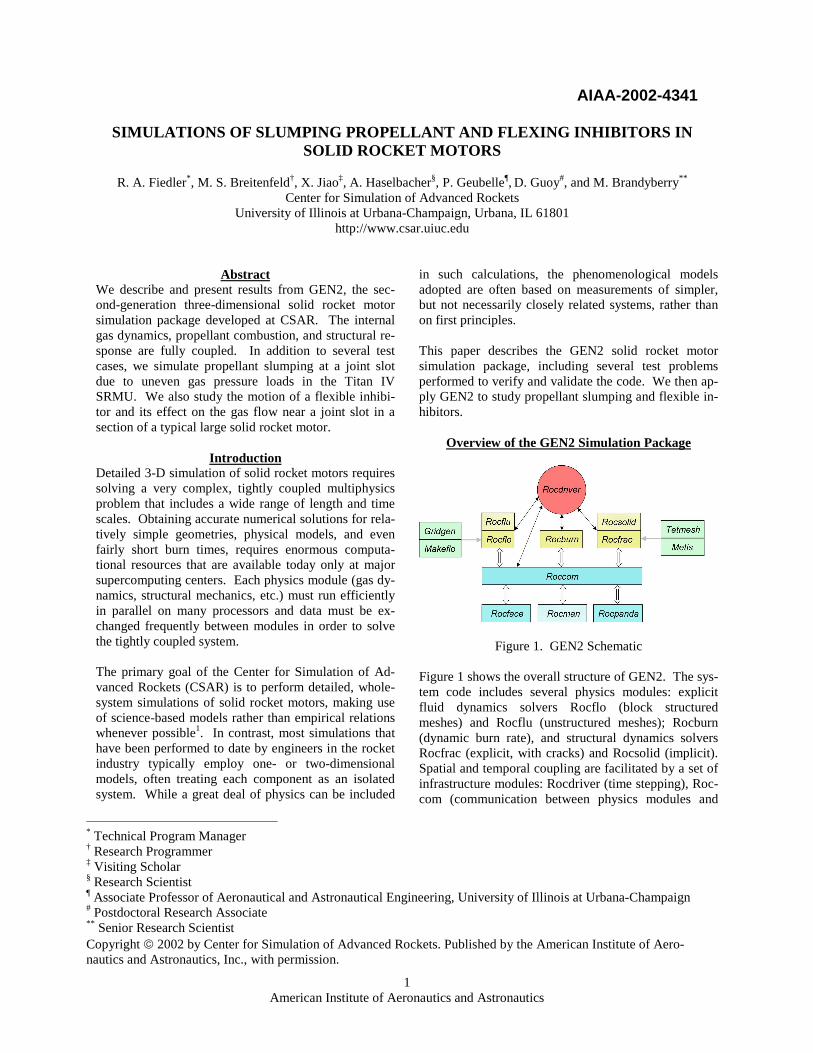
Figschfromstepprevtion
All processors first execute Rocfrac to determine the structural response of the propellant, case, insulation, etc., given the load (traction tf) applied by the fluid on the solid surface at time level n. The time step used by an explicit solver is limited by the Courant stability condition (essentially the shortest time for disturbances to propagate across an element anywhere in the mesh), and may be several times shorter than the system time step. We choose a constant system time step that is small enough to provide high accuracy in time, while still large enough to avoid computational overhead as-sociated with data transfer. (This topic is discussed fur-ther below.) Rocfrac takes as many solids Courant condition-limited time steps (“subcycles”) as necessary to obtain a solution at time level n+1 (using the traction from level n). The new surface position, the velocity of the surface r� , and the deformation velocity vs at level n+1 are then passed (indirectly) to the fluids solver. A set of fluids boundary values on the fluids mesh is computed next, given the surface motion defined on the solids surface mesh and the burning mass flux m com-puted by Rocburn. Rocface interpolates the various physical quantities to obtain their values at points on the fluids mesh. Rocman then applies jump conditions derived from conservation of mass and momentum across the thin combustion interface. All processors then execute Rocflo to evolve the fluid flow from level n to level n+1 taking as many fluids Courant condition-limited time steps as necessary. The motion of fluid/structure boundaries (burning or not) is interpolated linearly in time over the fluids time steps. Finally, the new tractions applied by the fluid on the solid surfaces are computed in Rocman and passed through Rocface to the solids solver Rocfrac, and the system time step is complete. If we were to use our implicit structural mechanics solver Rocsolid in place of Rocfrac, the solids time step would be limited only by accuracy considerations and can therefore be much larger than the solids Courant limit. In this case, the time stepping scheme described above is modified to improve overall accuracy. The implicit solver requires knowledge of the tractions at time level n+1 as well as at time n. We employ a pre-
Figure 2. GEN2 explicit time stepping scheme2
American Institute of Aeronautics and Astronautics
ure 2 illustrates our explicit temporal coupling eme. The objective is to advance the system in time
level n to level n+1, i.e., to take one system time ∆tn. The solution is known at time level n from the ious system time step or from a set of initial condi-s.
dictor-corrector method in which the tractions from the old time level are used during the predictor phase, and then the system time step is repeated one or more times during the corrector phase until the changes in the trac-tions, surface motion, etc., at time level n+1 from one corrector iteration to the next all lie below prescribed tolerances. This implicit/explicit coupling scheme is
3
American Institute of Aeronautics and Astronautics
similar to the one used in GEN1, our previous genera-tion integrated rocket simulation package4. In the next several subsections, we describe in more de-tail the individual components of the GEN2 package, particularly those which were not included in GEN1. Rocsolid is described in detail elsewhere5, while Rocflu is currently under development. Fluid Dynamics Solver: Rocflo Rocflo is a general-purpose Computational Fluid Dy-namics application which solves the compressible Euler or Navier-Stokes equations in Cartesian coordinates on structured, multiblock moving meshes using a finite volume method. The Arbitrary Lagrangian-Eulerian (ALE) formulation of the fluid equations in Rocflo takes into account the change in the fluid variables due to the motion of the walls of each finite volume as the mesh stretches to accommodate changes in surface ge-ometry (e.g., due to deformation and burning of the pro-pellant). The mesh inside each block is kept reasonably regular (smoothly changing mesh spacing, angles be-tween cell sides not far from 90 degrees) by prescribing a nodal velocity derived from automatic mesh genera-tion based on transfinite interpolation in two dimen-sions (not in the azimuthal direction). The spatial discretization schemes implemented in Rocflo include the central scheme with artificial dissi-pation6 and Roe’s upwind scheme7. The discrete equa-tions are integrated in time using an explicit multistage Runge-Kutta method. A two-stage method is com-monly chosen, where the time step is equal to the small-est value of the Courant time step among all fluid cells. The initial fluids mesh is created using the Gridgen mesh generation package from Pointwise, Inc8. The mesh is subsequently partitioned for parallel computa-tion using Makeflo, a tool developed at CSAR by Orion Sky Lawlor and Mark Brandyberry. This tool also pro-duces an input file for Rocflo that describes the block connectivity and boundary conditions. More detailed information on Rocflo, including results for validation cases and parallel performance studies for problems of fixed size and scaled size, is provided else-where9. Rocflo has recently been extended to include aluminum droplets, smoke particles, and various chemi-cal species10. However, the results presented here in-volve strictly single-phase flows. Structural Mechanics Solver: Rocfrac Rocfrac is a general-purpose structural mechanics ap-plication which computes the response of the propel-
lant, case, insulation, and nozzle, using the finite ele-ment method and explicit time steps. Since propellants burn away, nozzles may suffer ablation, etc., the equa-tions of motion are written using an ALE formulation (as described above) to accurately treat such mass losses. The mesh is kept reasonably smooth by pre-scribing a grid velocity derived from the solution of a parabolic system of equations in 3D designed to propa-gate the motion of the surface (with respect to the unde-formed configuration) throughout the structural domain. In addition to ordinary 4-node tetrahedral finite ele-ments, Rocfrac features higher-order elements (10-node tetrahedral) to improve accuracy. Rocfrac can also util-ize cohesive finite volume elements, which fit between the tetrahedral finite elements and can stretch (up to a certain amount) and then fail under a sufficiently large tensile load. This allows the scheme to follow cracks propagating in any direction11. Rocfrac is applicable to situations with large deforma-tions, and includes linear and non-linear material prop-erties, such as the Arruda-Boyce model12, which is ap-propriate for the rubbery, nearly incompressible materials that comprise solid propellants. Burn Rate: Rocburn Rocburn (implemented in the coupled code by K. C. Tang) computes the unsteady burning rate of solid pro-pellant using a nonlinear dynamic solid propellant com-bustion model. The theory of Zeldovich and Novoz-hilov (ZN) is used in combination with the Flame Modeling (FM) approach13,14. For homogeneous solid propellant combustion, WSB flame modeling15 is used. To simulate the combustion of AP composite propel-lant, an empirical expression replaces premixed WSB flame modeling16. At each fluid cell face on the burning propellant sur-face, the one-dimensional (into the propellant) unsteady energy equation in the condensed phase and an equation for the unsteady burning rate eigenvalue are solved for a prescribed unsteady pressure. Under rapid pressuriza-tion rates, the unsteady dynamic burning rate can be significantly different from the burning rate predicted by the quasi-steady combustion model due to the ther-mal relaxation effect in the solid. Orchestration: Rocdriver The Rocdriver module orchestrates the execution of the other modules in the GEN2 code. It controls execution of the time stepping algorithm, initialization of the physics applications and some of the infrastructure
4
American Institute of Aeronautics and Astronautics
modules, creation of output dumps, and collection of performance data. The heart of Rocdriver is a loop over system time steps. This loop implements our explicit/explicit and im-plicit/explicit predictor-corrector temporal coupling schemes described above. GEN2 also has a small main program written in C++ that directly calls Rocdriver. Its primary purpose is to read command line options that allow the user to spec-ify which physics applications should be active and which ones should be inactive (“dummy” versions are to be loaded instead). This makes it convenient to test one physics application separately from the others without having to maintain separate, stand-alone ver-sions of each module. Communication: Roccom Roccom is a set of library routines that are used to send data from one module to another. The physics applica-tions call some Roccom routines to specify which data is to be exchanged with which applications and which data should be included in an output dump. Other Roc-com routines are called by Rocdriver (or by the applica-tions directly, where appropriate) to actually exchange the data or to write the output. The benefit of using Roccom is that the details of how these operations are carried out by the infrastructure modules are hidden from the applications programmers. For example, a few calls to Roccom routines enable an application to take advantage of the parallel I/O capabilities of GEN2 without directly calling any parallel I/O routines. Data Transfer Across Interfaces: Rocface
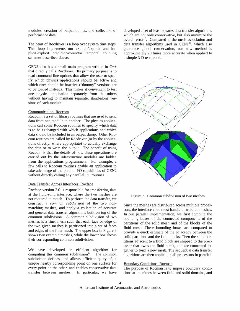
Rocface version 2.0 is responsible for transferring data at the fluid-solid interface, where the two meshes are not required to match. To perform the data transfer, we construct a common subdivision of the two non-matching meshes, and apply a collection of accurate and general data transfer algorithms built on top of the common subdivision. A common subdivision of two meshes is a finer mesh such that each face or edge of the two given meshes is partitioned into a set of faces and edges of the finer mesh. The upper box in Figure 3 shows two example meshes, while the lower box shows their corresponding common subdivision.
We have developed an efficient algorithm for computing this common subdivision17. The common subdivision defines, and allows efficient query of, a unique nearby corresponding point on one surface for every point on the other, and enables conservative data transfer between meshes. In particular, we have
developed a set of least-squares data transfer algorithms which are not only conservative, but also minimize the overall error18. Compared to the mesh association and data transfer algorithms used in GEN119, which also guarantee global conservation, our new method is approximately 20 times more accurate when applied to a simple 3-D test problem.
Figure 3. Common subdivision of two meshes Since the meshes are distributed across multiple proces-sors, the interface code must handle distributed meshes. In our parallel implementation, we first compute the bounding boxes of the connected components of the partitions of the solid mesh and of the blocks of the fluid mesh. These bounding boxes are compared to provide a quick estimate of the adjacency between the solid partitions and the fluid blocks. Then the solid par-titions adjacent to a fluid block are shipped to the proc-essor that owns the fluid block, and are connected to-gether to form a new mesh. The sequential data transfer algorithms are then applied on all processors in parallel. Boundary Conditions: Rocman The purpose of Rocman is to impose boundary condi-tions at interfaces between fluid and solid domains, and
5
American Institute of Aeronautics and Astronautics
to propagate regressing interfaces such as burning pro-pellant surfaces. For historical reasons, the functions of this module are currently contained within the GEN2 fluids and solids solvers, but we are gathering these procedures together into a new infrastructure module so that it will be easier to incorporate new physics applica-tions into GEN2. Parallel I/O: Rocpanda Rocdriver calls the output routines in each physics module immediately after the physical problem time advances beyond the “nth” evenly spaced output time, where “n” ranges from zero to typically hundreds of output dump times. In a parallel computation, the simplest way to dump output is to have each processor write its data to a sepa-rate file, and use a visualization tool that can merge the blocks into a single image. If the problem and the num-ber of processors is very large, a huge amount of data is written to disk at once, overwhelming the I/O system and possibly delaying the calculation. To avoid this problem and to combine the output into a more man-ageable number of files, we use Rocpanda20, which is an extension of the PANDA21 library for GEN2. It uses additional processors (called Rocpanda servers) to col-lect output data (sent as messages using MPI) from the compute processors (called Rocpanda clients) and write it to disk while the compute processors proceed with the calculation. This helps because it usually takes sig-nificantly less time to send the data over the internal network of a large parallel machine than it does to write it to hard disk. The amount of memory available to the servers should be sufficient to hold one output dump to avoid forcing the clients to wait for disk writes to com-plete. Visualization: Rocketeer John Norris and Robert Fiedler have developed a suite of powerful, general purpose tools for scientific visuali-zation called Rocketeer22. Rocketeer is based on the Visualization Toolkit23 , which uses OpenGL to exploit hardware graphics acceleration. Rocketeer executables for AIX, Linux, Microsoft Windows, and Solaris can be downloaded free of charge. Rocketeer can display scalars, vectors, and tensors de-fined on many types of grids using a variety of tech-niques. It has an extremely user-friendly GUI and makes use of attributes stored with the data in HDF for-mat24 files to minimize the effort required to create im-ages. In addition to the original, single workstation version
(simply called “Rocketeer”), an MPI parallel batch mode version called “Voyager” is available25. Each CPU running Voyager processes concurrently an entire snapshot from a series of dumps generated by a simula-tion and saves the images to disk for animation.. The camera position and list of graphics operations to be performed are saved during an interactive session of Rocketeer and are read in by Voyager. A client/server implementation of Rocketeer called “Apollo/Houston” has recently been developed. The client runs on a desktop system and takes advantage of graphics hardware acceleration, while the server is an MPI parallel component that runs on the remote ma-chine where the data resides. This greatly reduces the amount of data that needs to be transferred to visualize the data, since only the lines and polygons to be ren-dered at the desktop are sent over the network. The parallel server is faster than a serial version would be, and it can take advantage of more memory available on a distributed memory system.
Verification and Validation
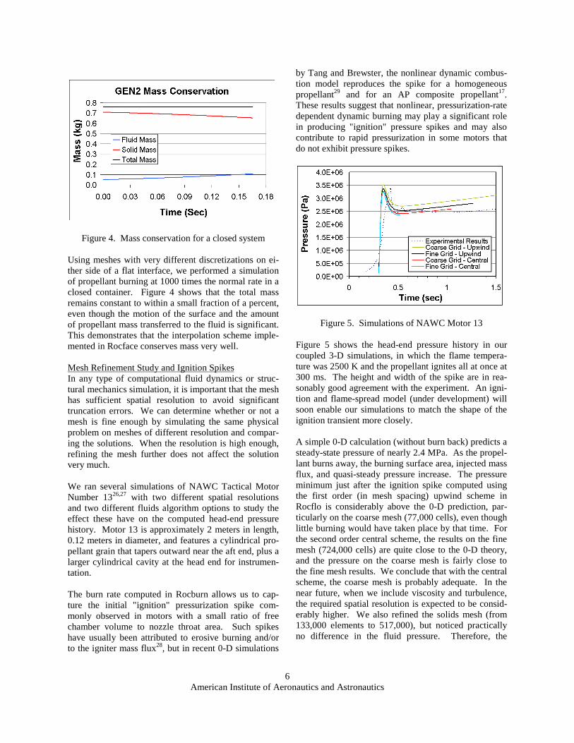
In this section we present results from various test prob-lems to verify that GEN2 solves the prescribed equa-tions accurately, and to validate that the included phys-ics reflects a real system by comparing numerical results with performance data from actual rockets. Mass Conservation Since the performance of a rocket is quite sensitive to the mass flux injected into the chamber, it is important that the overall numerical scheme be constructed to conserve mass. The finite volume formulation of the fluid equations in Rocflo guarantees that mass, linear momentum, and energy are not created or destroyed due to truncation errors. This is accomplished by im-plementing the conservation laws in terms of the fluxes of mass, etc., through the walls of each mesh cell. The flux leaving a given face of one mesh cell exactly equals the flux entering the neighboring cell that shares that face. Therefore, the fluid domain can lose or gain mass only through faces along the boundaries, no mat-ter how coarse the mesh is or how much it moves. In a closed system, e.g., a slab of propellant burning in a closed container, the mass leaving the solid domain should equal the mass entering the fluid domain. This requirement is particularly challenging to satisfy when the fluids and solids meshes do not match at the inter-face – not only may the discretizations be different on each side, but even the geometrical surfaces along which the nodes on each side lie may not quite coin-cide.
6
American Institute of Aeronautics and Astronautics
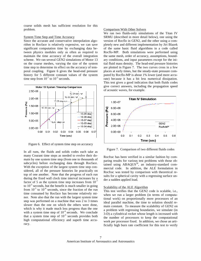
Figure 4. Mass conservation for a closed system Using meshes with very different discretizations on ei-ther side of a flat interface, we performed a simulation of propellant burning at 1000 times the normal rate in a closed container. Figure 4 shows that the total mass remains constant to within a small fraction of a percent, even though the motion of the surface and the amount of propellant mass transferred to the fluid is significant. This demonstrates that the interpolation scheme imple-mented in Rocface conserves mass very well. Mesh Refinement Study and Ignition Spikes In any type of computational fluid dynamics or struc-tural mechanics simulation, it is important that the mesh has sufficient spatial resolution to avoid significant truncation errors. We can determine whether or not a mesh is fine enough by simulating the same physical problem on meshes of different resolution and compar-ing the solutions. When the resolution is high enough, refining the mesh further does not affect the solution very much. We ran several simulations of NAWC Tactical Motor Number 1326,27 with two different spatial resolutions and two different fluids algorithm options to study the effect these have on the computed head-end pressure history. Motor 13 is approximately 2 meters in length, 0.12 meters in diameter, and features a cylindrical pro-pellant grain that tapers outward near the aft end, plus a larger cylindrical cavity at the head end for instrumen-tation. The burn rate computed in Rocburn allows us to cap-ture the initial "ignition" pressurization spike com-monly observed in motors with a small ratio of free chamber volume to nozzle throat area. Such spikes have usually been attributed to erosive burning and/or to the igniter mass flux28, but in recent 0-D simulations
by Tang and Brewster, the nonlinear dynamic combus-tion model reproduces the spike for a homogeneous propellant29 and for an AP composite propellant17. These results suggest that nonlinear, pressurization-rate dependent dynamic burning may play a significant role in producing "ignition" pressure spikes and may also contribute to rapid pressurization in some motors that do not exhibit pressure spikes.
Figure 5. Simulations of NAWC Motor 13 Figure 5 shows the head-end pressure history in our coupled 3-D simulations, in which the flame tempera-ture was 2500 K and the propellant ignites all at once at 300 ms. The height and width of the spike are in rea-sonably good agreement with the experiment. An igni-tion and flame-spread model (under development) will soon enable our simulations to match the shape of the ignition transient more closely. A simple 0-D calculation (without burn back) predicts a steady-state pressure of nearly 2.4 MPa. As the propel-lant burns away, the burning surface area, injected mass flux, and quasi-steady pressure increase. The pressure minimum just after the ignition spike computed using the first order (in mesh spacing) upwind scheme in Rocflo is considerably above the 0-D prediction, par-ticularly on the coarse mesh (77,000 cells), even though little burning would have taken place by that time. For the second order central scheme, the results on the fine mesh (724,000 cells) are quite close to the 0-D theory, and the pressure on the coarse mesh is fairly close to the fine mesh results. We conclude that with the central scheme, the coarse mesh is probably adequate. In the near future, when we include viscosity and turbulence, the required spatial resolution is expected to be consid-erably higher. We also refined the solids mesh (from 133,000 elements to 517,000), but noticed practically no difference in the fluid pressure. Therefore, the
7
American Institute of Aeronautics and Astronautics
coarse solids mesh has sufficient resolution for this problem. System Time Step and Time Accuracy Since the accurate and conservative interpolation algo-rithm in Rocface is relatively expensive, we can save significant computation time by exchanging data be-tween physics modules only as often as required to maintain the time accuracy of the overall integration scheme. We ran several GEN2 simulations of Motor 13 on the coarse meshes, varying the size of the system time step to determine its effect on the accuracy of tem-poral coupling. Figure 6 gives the head-end pressure history for 5 different constant values of the system time step from 10-7 to 10-3 seconds.
Figure 6. Effect of system time step on accuracy In all runs, the fluids and solids codes each take as many Courant time steps as needed to evolve their do-main by one system time step (from one to thousands of subcycles) before exchanging data through Rocface. With the exception of the largest system time step con-sidered, all of the pressure histories lie practically on top of one another. Note that the progress of each run during the fixed wall clock time interval increases by a factor of 5 as the system time step increases from 10-7 to 10-5 seconds, but the benefit is much smaller in going from 10-5 to 10-4 seconds, since the fraction of the run time consumed by Rocface has become relatively mi-nor. Note also that the run with the largest system time step was performed on a machine that was 2 to 3 times slower than the one on which the others were done, which is why it made much less progress than the one with a system time step of 10-4 seconds. We conclude that a system time step of 10-5 seconds provides both high computational efficiency and superb time accu-racy.
Comparison With Other Solvers We ran two fluids-only simulations of the Titan IV SRMU (described in more detail below), one using the version of Rocflo in GEN2, and the other using a com-pletely new and different implementation by Jiri Blazek of the same basic fluid algorithms in a code called Rocflo-MP. Both simulations were performed using the same mesh, order of accuracy, assumptions, bound-ary conditions, and input parameters except for the ini-tial fluid mass density. The head-end pressure histories are plotted in Figure 7. The two curves cross in a few places at early times, but the steady-state pressure com-puted by Rocflo-MP is about 1% lower (and more accu-rate) because it has a bit less numerical dissipation. This test gives a good indication that both fluids codes give correct answers, including the propagation speed of acoustic waves, for example.
Figure 7. Comparison of two different fluids codes Rocfrac has been verified in a similar fashion by com-paring results for various test problems with those ob-tained using ABAQUS30, an industry-standard com-mercial code. In addition, the ALE formulation in Rocfrac was tested by comparison with theoretical re-sults for a spherical cavity with a regressing surface un-der a sudden applied load. Scalability of the ALE Algorithm This test verifies that the GEN2 code is scalable, i.e., when we run a larger problem (in terms of computa-tional work) on proportionally more processors of an ideal parallel machine, the time to solution should re-main constant. To measure the scalability of GEN2 on a problem with regressing boundaries, we simulate (in 3-D) a cylindrical rocket whose length is increased with the number of processors to keep the computational work per processor fixed. In addition, we chose an arti-ficially high burn rate coefficient for this test to verify
8
American Institute of Aeronautics and Astronautics
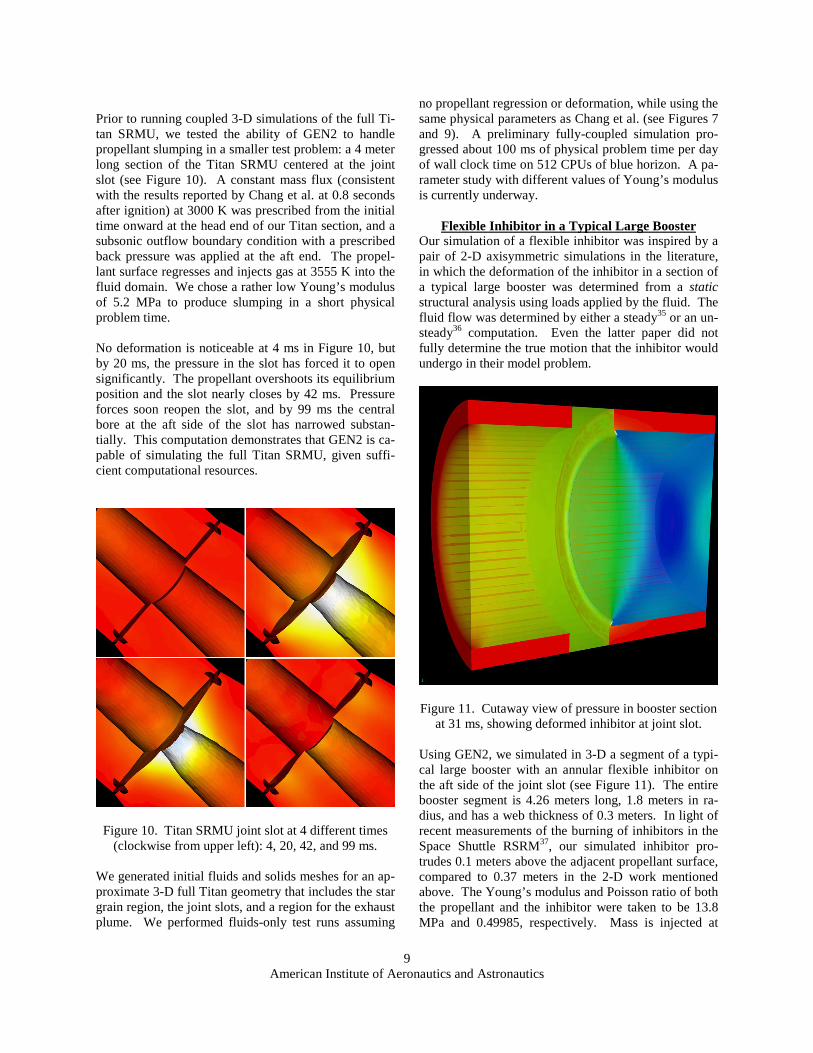
that the fluid and solid meshes remain together at the burning surface. Figure 8 shows the wall clock time for Rocflo (top), Rocface (middle – “Motion” plus “Traction”), and Rocfrac (bottom) during one system time step on an IBM SP (blue horizon31). Scalability is excellent even for very large numbers of processors. In this test case, the system time step (10-7 seconds) is shorter than the solids and fluids Courant time steps, and therefore data is exchanged between the two modules much more of-ten than necessary for accurate temporal coupling. Consequently, a disproportionately large fraction of the time is spent in Rocface. In production runs, we nor-mally use a system time step of 10-5 seconds as dis-cussed above. The dynamic burn rate calculation in Rocburn uses a negligible amount of CPU time, so it is not included in the figure.
Figire 8. Scalability of GEN2
Slumping in the TITAN IV SRMU
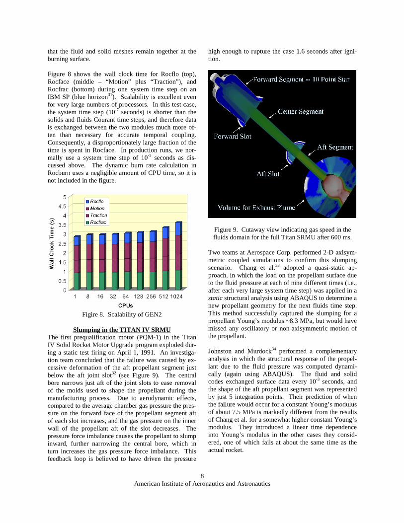
The first prequalification motor (PQM-1) in the Titan IV Solid Rocket Motor Upgrade program exploded dur-ing a static test firing on April 1, 1991. An investiga-tion team concluded that the failure was caused by ex-cessive deformation of the aft propellant segment just below the aft joint slot32 (see Figure 9). The central bore narrows just aft of the joint slots to ease removal of the molds used to shape the propellant during the manufacturing process. Due to aerodynamic effects, compared to the average chamber gas pressure the pres-sure on the forward face of the propellant segment aft of each slot increases, and the gas pressure on the inner wall of the propellant aft of the slot decreases. The pressure force imbalance causes the propellant to slump inward, further narrowing the central bore, which in turn increases the gas pressure force imbalance. This feedback loop is believed to have driven the pressure
high enough to rupture the case 1.6 seconds after igni-tion.
Figure 9. Cutaway view indicating gas speed in the fluids domain for the full Titan SRMU after 600 ms.
Two teams at Aerospace Corp. performed 2-D axisym-metric coupled simulations to confirm this slumping scenario. Chang et al.33 adopted a quasi-static ap-proach, in which the load on the propellant surface due to the fluid pressure at each of nine different times (i.e., after each very large system time step) was applied in a static structural analysis using ABAQUS to determine a new propellant geometry for the next fluids time step. This method successfully captured the slumping for a propellant Young’s modulus ~8.3 MPa, but would have missed any oscillatory or non-axisymmetric motion of the propellant. Johnston and Murdock34 performed a complementary analysis in which the structural response of the propel-lant due to the fluid pressure was computed dynami-cally (again using ABAQUS). The fluid and solid codes exchanged surface data every 10-3 seconds, and the shape of the aft propellant segment was represented by just 5 integration points. Their prediction of when the failure would occur for a constant Young’s modulus of about 7.5 MPa is markedly different from the results of Chang et al. for a somewhat higher constant Young’s modulus. They introduced a linear time dependence into Young’s modulus in the other cases they consid-ered, one of which fails at about the same time as the actual rocket.
9
American Institute of Aeronautics and Astronautics
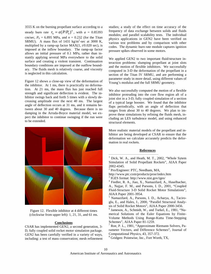
Prior to running coupled 3-D simulations of the full Ti-tan SRMU, we tested the ability of GEN2 to handle propellant slumping in a smaller test problem: a 4 meter long section of the Titan SRMU centered at the joint slot (see Figure 10). A constant mass flux (consistent with the results reported by Chang et al. at 0.8 seconds after ignition) at 3000 K was prescribed from the initial time onward at the head end of our Titan section, and a subsonic outflow boundary condition with a prescribed back pressure was applied at the aft end. The propel-lant surface regresses and injects gas at 3555 K into the fluid domain. We chose a rather low Young’s modulus of 5.2 MPa to produce slumping in a short physical problem time. No deformation is noticeable at 4 ms in Figure 10, but by 20 ms, the pressure in the slot has forced it to open significantly. The propellant overshoots its equilibrium position and the slot nearly closes by 42 ms. Pressure forces soon reopen the slot, and by 99 ms the central bore at the aft side of the slot has narrowed substan-tially. This computation demonstrates that GEN2 is ca-pable of simulating the full Titan SRMU, given suffi-cient computational resources.
Figure 10. Titan SRMU joint slot at 4 different times (clockwise from upper left): 4, 20, 42, and 99 ms.
We generated initial fluids and solids meshes for an ap-proximate 3-D full Titan geometry that includes the star grain region, the joint slots, and a region for the exhaust plume. We performed fluids-only test runs assuming
no propellant regression or deformation, while using the same physical parameters as Chang et al. (see Figures 7 and 9). A preliminary fully-coupled simulation pro-gressed about 100 ms of physical problem time per day of wall clock time on 512 CPUs of blue horizon. A pa-rameter study with different values of Young’s modulus is currently underway.
Flexible Inhibitor in a Typical Large Booster
Our simulation of a flexible inhibitor was inspired by a pair of 2-D axisymmetric simulations in the literature, in which the deformation of the inhibitor in a section of a typical large booster was determined from a static structural analysis using loads applied by the fluid. The fluid flow was determined by either a steady35 or an un-steady36 computation. Even the latter paper did not fully determine the true motion that the inhibitor would undergo in their model problem.
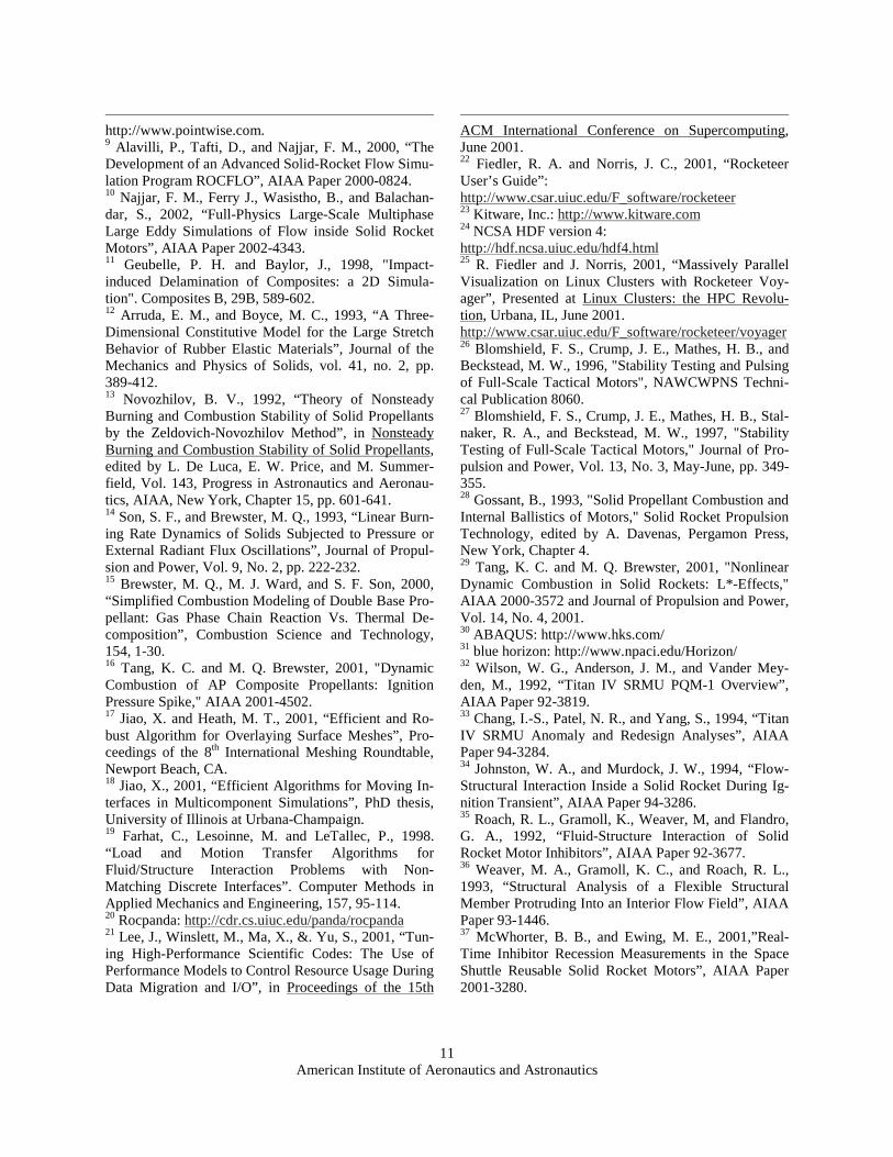
Figure 11. Cutaway view of pressure in booster section
at 31 ms, showing deformed inhibitor at joint slot. Using GEN2, we simulated in 3-D a segment of a typi-cal large booster with an annular flexible inhibitor on the aft side of the joint slot (see Figure 11). The entire booster segment is 4.26 meters long, 1.8 meters in ra-dius, and has a web thickness of 0.3 meters. In light of recent measurements of the burning of inhibitors in the Space Shuttle RSRM37, our simulated inhibitor pro-trudes 0.1 meters above the adjacent propellant surface, compared to 0.37 meters in the 2-D work mentioned above. The Young’s modulus and Poisson ratio of both the propellant and the inhibitor were taken to be 13.8 MPa and 0.49985, respectively. Mass is injected at
10
American Institute of Aeronautics and Astronautics
3555 K on the burning propellant surface according to a
steady burn rate nPPar )/( 0b = , with a = 0.85393
cm/sec, P0 = 6.895 MPa, and n = 0.232 (for the Titan SRMU). A mass flux of 1431 kg/m2-sec at 3000 K, multiplied by a ramp-up factor MAX(1, t/0.020 sec), is imposed at the inflow boundary. The ramp-up factor allows an initial pressure of 0.1 MPa, rather than in-stantly applying several MPa everywhere to the solid surface and creating a violent transient. Continuation boundary conditions are imposed at the outflow bound-ary. The fluids mesh is relatively coarse, and viscosity is neglected in this calculation. Figure 12 shows a close-up view of the deformation of the inhibitor. At 1 ms, there is practically no deforma-tion. At 21 ms, the mass flux has just reached full strength and significant deflection is evident. The in-hibitor swings back and forth 5 times with a slowly de-creasing amplitude over the next 40 ms. The largest angle of deflection occurs at 31 ms, and it remains be-tween about 30 and 40 degrees. Because there is no damping in the Arruda-Boyce material model, we ex-pect the inhibitor to continue swinging if the run were to be extended.
Figure 12. Flexible inhibitor at 4 different times (clockwise from upper left): 1, 21, 31, and 61 ms.
Conclusions
CSAR has implemented GEN2, a second generation, 3-D, fully coupled solid rocket motor simulation package. GEN2 has been carefully verified in a variety of ways, including: a test of mass conservation; mesh refinement
studies; a study of the effect on time accuracy of the frequency of data exchange between solids and fluids modules; and parallel scalability tests. The individual physics applications in GEN2 have been verified on various test problems and by comparison with other codes. The dynamic burn rate module captures ignition pressure spikes observed in some motors. We applied GEN2 to two important fluid/structure in-teraction problems: slumping propellant at joint slots and the motion of flexible inhibitors. We successfully computed in 3-D the deformation of the propellant in a section of the Titan IV SRMU, and are performing a parameter study in more detail, using different values of Young’s modulus and the full SRMU geometry. We also successfully computed the motion of a flexible inhibitor protruding into the core flow region aft of a joint slot in a 3-D, fully coupled simulation of a section of a typical large booster. We found that the inhibitor flaps periodically, with an angle of deflection that ranges from about 30 to 40 degrees. We plan to im-prove these simulations by refining the fluids mesh, in-cluding an LES turbulence model, and using enhanced structural elements. More realistic material models of the propellant and in-hibitor are being developed at CSAR to ensure that the deformation we calculate accurately predicts the defor-mation in real rockets.
References
1 Dick, W. A., and Heath, M. T., 2002, “Whole Sytem Simulation of Solid Propellant Rockets”, AIAA Paper 2002-4345. 2 Pro/Engineer: PTC, Needham, MA, http://www.ptc.com/products/proe/index.htm 3 IGES format: http://www.nist.gov/iges/ 4 Fiedler, R. A., Jiao, X., Namazifard, A., Haselbacher, A., Najjar, F. M., and Parsons, I. D., 2001, “Coupled Fluid-Structure 3-D Solid Rocket Motor Simulations”, AIAA Paper 2001-3954. 5 Namazifard, A., Parsons, I. D., Acharya, A., Taciro-glu, E., and Hales, J., 2000, “Parallel Structural Analy-sis of Solid Rocket Motors”, AIAA Paper 2000-3456. 6 Jameson, A., Schmidt, W., and Turkel, E., 1981, “Nu-merical Solutions of the Euler Equations by Finite-Volume Methods Using Runge-Kutta Time-Stepping Schemes”, AIAA Paper 81-1259. 7 Roe, P. L., 1981, “Approximate Riemann Solvers, Pa-rameter Vectors, and Difference Schemes”, Journal of Computational Physics, 43, 357-372. 8 Gridgen: Pointwise, Inc., Fort Worth, TX,
11
American Institute of Aeronautics and Astronautics
http://www.pointwise.com. 9 Alavilli, P., Tafti, D., and Najjar, F. M., 2000, “The Development of an Advanced Solid-Rocket Flow Simu-lation Program ROCFLO”, AIAA Paper 2000-0824. 10 Najjar, F. M., Ferry J., Wasistho, B., and Balachan-dar, S., 2002, “Full-Physics Large-Scale Multiphase Large Eddy Simulations of Flow inside Solid Rocket Motors”, AIAA Paper 2002-4343. 11 Geubelle, P. H. and Baylor, J., 1998, "Impact-induced Delamination of Composites: a 2D Simula-tion". Composites B, 29B, 589-602. 12 Arruda, E. M., and Boyce, M. C., 1993, “A Three-Dimensional Constitutive Model for the Large Stretch Behavior of Rubber Elastic Materials”, Journal of the Mechanics and Physics of Solids, vol. 41, no. 2, pp. 389-412. 13 Novozhilov, B. V., 1992, “Theory of Nonsteady Burning and Combustion Stability of Solid Propellants by the Zeldovich-Novozhilov Method”, in Nonsteady Burning and Combustion Stability of Solid Propellants, edited by L. De Luca, E. W. Price, and M. Summer-field, Vol. 143, Progress in Astronautics and Aeronau-tics, AIAA, New York, Chapter 15, pp. 601-641. 14 Son, S. F., and Brewster, M. Q., 1993, “Linear Burn-ing Rate Dynamics of Solids Subjected to Pressure or External Radiant Flux Oscillations”, Journal of Propul-sion and Power, Vol. 9, No. 2, pp. 222-232. 15 Brewster, M. Q., M. J. Ward, and S. F. Son, 2000, “Simplified Combustion Modeling of Double Base Pro-pellant: Gas Phase Chain Reaction Vs. Thermal De-composition”, Combustion Science and Technology, 154, 1-30. 16 Tang, K. C. and M. Q. Brewster, 2001, "Dynamic Combustion of AP Composite Propellants: Ignition Pressure Spike," AIAA 2001-4502. 17 Jiao, X. and Heath, M. T., 2001, “Efficient and Ro-bust Algorithm for Overlaying Surface Meshes”, Pro-ceedings of the 8th International Meshing Roundtable, Newport Beach, CA. 18 Jiao, X., 2001, “Efficient Algorithms for Moving In-terfaces in Multicomponent Simulations”, PhD thesis, University of Illinois at Urbana-Champaign. 19 Farhat, C., Lesoinne, M. and LeTallec, P., 1998. “Load and Motion Transfer Algorithms for Fluid/Structure Interaction Problems with Non-Matching Discrete Interfaces”. Computer Methods in Applied Mechanics and Engineering, 157, 95-114. 20 Rocpanda: http://cdr.cs.uiuc.edu/panda/rocpanda 21 Lee, J., Winslett, M., Ma, X., &. Yu, S., 2001, “Tun-ing High-Performance Scientific Codes: The Use of Performance Models to Control Resource Usage During Data Migration and I/O”, in Proceedings of the 15th
ACM International Conference on Supercomputing, June 2001. 22 Fiedler, R. A. and Norris, J. C., 2001, “Rocketeer User’s Guide”: http://www.csar.uiuc.edu/F_software/rocketeer 23 Kitware, Inc.: http://www.kitware.com 24 NCSA HDF version 4: http://hdf.ncsa.uiuc.edu/hdf4.html 25 R. Fiedler and J. Norris, 2001, “Massively Parallel Visualization on Linux Clusters with Rocketeer Voy-ager”, Presented at Linux Clusters: the HPC Revolu-tion, Urbana, IL, June 2001. http://www.csar.uiuc.edu/F_software/rocketeer/voyager 26 Blomshield, F. S., Crump, J. E., Mathes, H. B., and Beckstead, M. W., 1996, "Stability Testing and Pulsing of Full-Scale Tactical Motors", NAWCWPNS Techni-cal Publication 8060. 27 Blomshield, F. S., Crump, J. E., Mathes, H. B., Stal-naker, R. A., and Beckstead, M. W., 1997, "Stability Testing of Full-Scale Tactical Motors," Journal of Pro-pulsion and Power, Vol. 13, No. 3, May-June, pp. 349-355. 28 Gossant, B., 1993, "Solid Propellant Combustion and Internal Ballistics of Motors," Solid Rocket Propulsion Technology, edited by A. Davenas, Pergamon Press, New York, Chapter 4. 29 Tang, K. C. and M. Q. Brewster, 2001, "Nonlinear Dynamic Combustion in Solid Rockets: L*-Effects," AIAA 2000-3572 and Journal of Propulsion and Power, Vol. 14, No. 4, 2001. 30 ABAQUS: http://www.hks.com/ 31 blue horizon: http://www.npaci.edu/Horizon/ 32 Wilson, W. G., Anderson, J. M., and Vander Mey-den, M., 1992, “Titan IV SRMU PQM-1 Overview”, AIAA Paper 92-3819. 33 Chang, I.-S., Patel, N. R., and Yang, S., 1994, “Titan IV SRMU Anomaly and Redesign Analyses”, AIAA Paper 94-3284. 34 Johnston, W. A., and Murdock, J. W., 1994, “Flow-Structural Interaction Inside a Solid Rocket During Ig-nition Transient”, AIAA Paper 94-3286. 35 Roach, R. L., Gramoll, K., Weaver, M, and Flandro, G. A., 1992, “Fluid-Structure Interaction of Solid Rocket Motor Inhibitors”, AIAA Paper 92-3677. 36 Weaver, M. A., Gramoll, K. C., and Roach, R. L., 1993, “Structural Analysis of a Flexible Structural Member Protruding Into an Interior Flow Field”, AIAA Paper 93-1446. 37 McWhorter, B. B., and Ewing, M. E., 2001,”Real-Time Inhibitor Recession Measurements in the Space Shuttle Reusable Solid Rocket Motors”, AIAA Paper 2001-3280.