Embed Size (px)
Citation preview
Simulation with TE connectors
Agilent High Speed Digital Tour
Emmanuel LANCELOT
+33 6 74 53 05 86

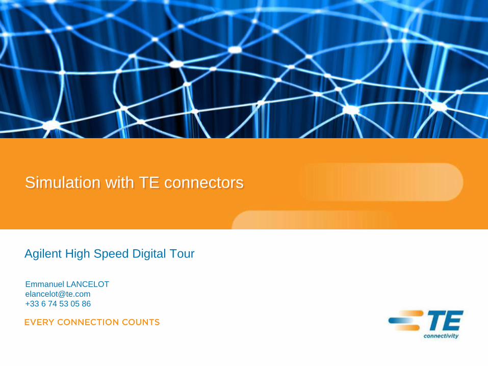
A WORLD LEADER IN CONNECTIVITY
• $13.3 billion global company
• Solving connectivity challenges with the broadest range of products
• Engineering driven, customer focused
• Leveraging technology innovations across industries
page 3
And Extensive Global Resources
Transportation Communications Energy Consumer
Products Industrial
Equipment
Aerospace
& Defense
Medical
Connectors Fiber Optics Circuit
Protection
Wireless Sealing &
Protection Precision
Wire & Cable
~90 Manufacturing Sites Serving Every Region
7,000 Engineers
Close to Our Customers
150 Countries
Served
5,000 Salespeople
Advising Our Customers
SubCom
Consumer Industrial and Infrastructure
With a Wealth of Technology Platforms
Serving Large Attractive Markets
TE Connectivity: A World Leader Enabling Connectivity
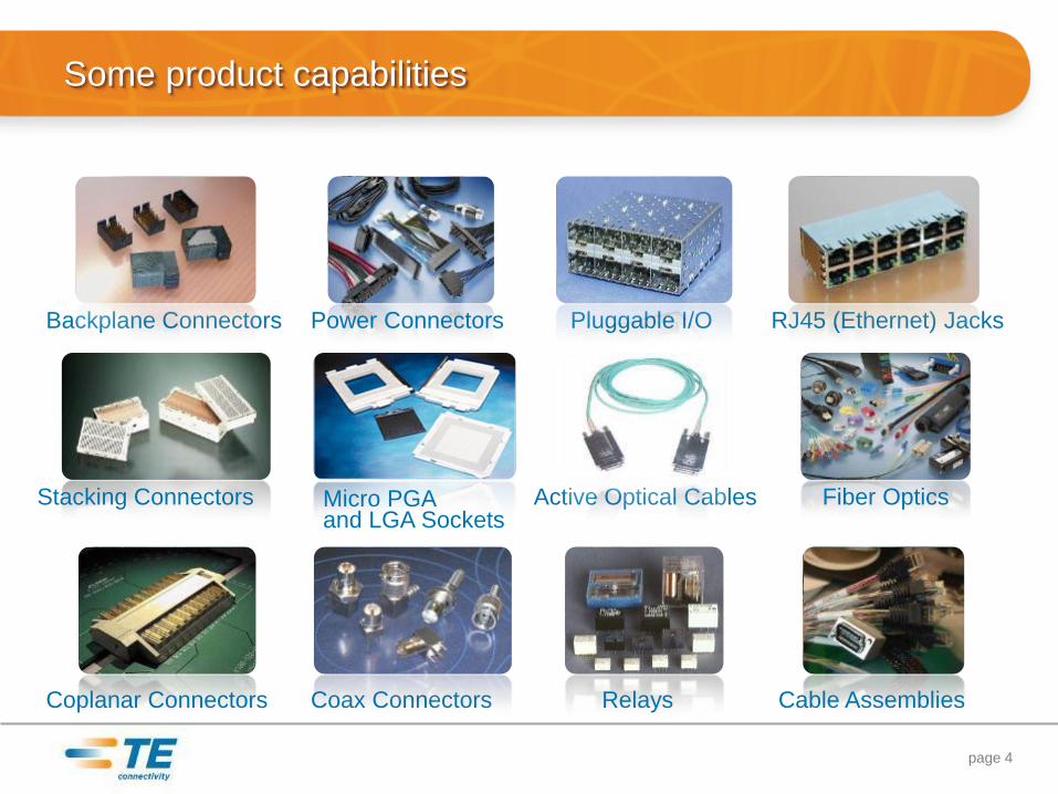
Some product capabilities
page 4
Backplane Connectors Pluggable I/O
Fiber Optics
Power Connectors
Stacking Connectors
RJ45 (Ethernet) Jacks
Coax Connectors Cable Assemblies Coplanar Connectors
Micro PGA and LGA Sockets
Active Optical Cables
Relays
Agenda
• How to find an electrical model for a TE connector?
• Simulation versus Measurement
• Simulation, connector choice and cost optimization
page 5
•Divider Slide Title How to find an electrical model for a TE connector?
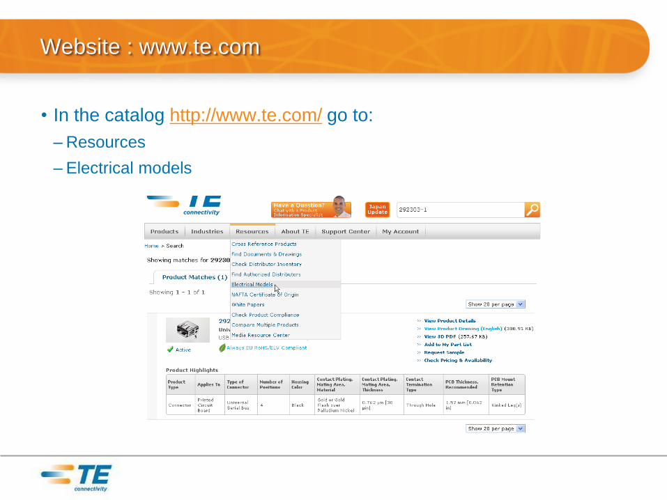
Website : www.te.com
• In the catalog http://www.te.com/ go to:
–Resources
– Electrical models
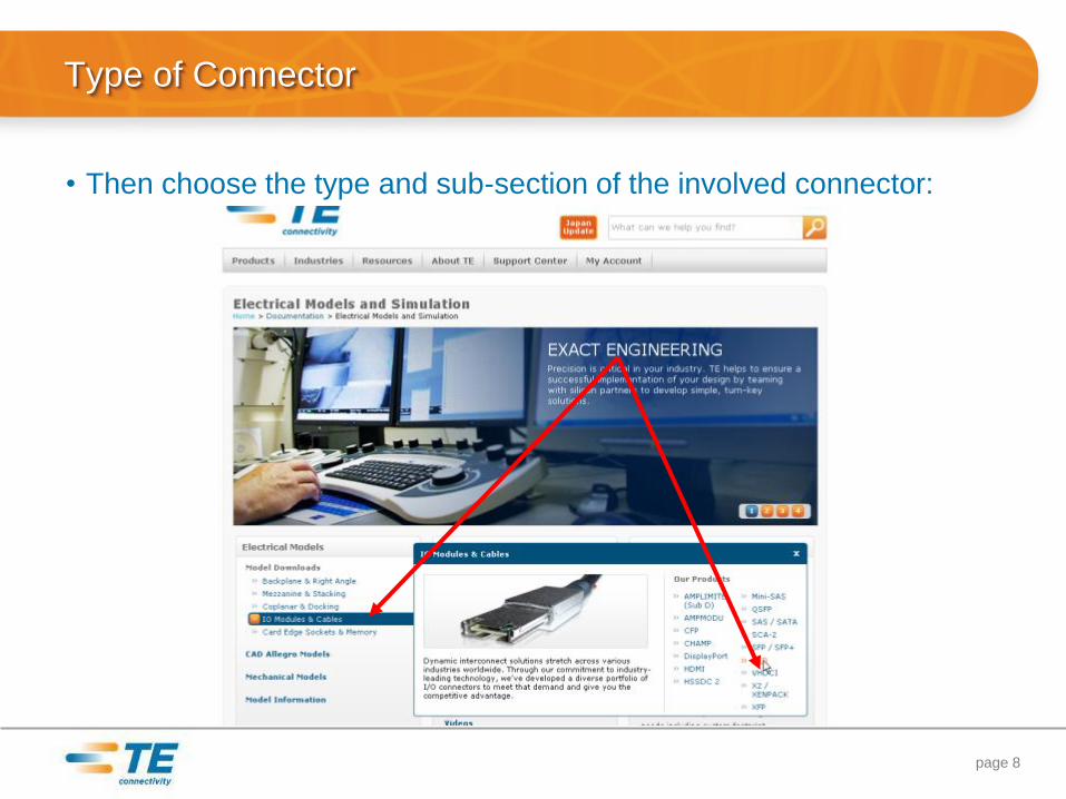
Type of Connector
page 8
• Then choose the type and sub-section of the involved connector:
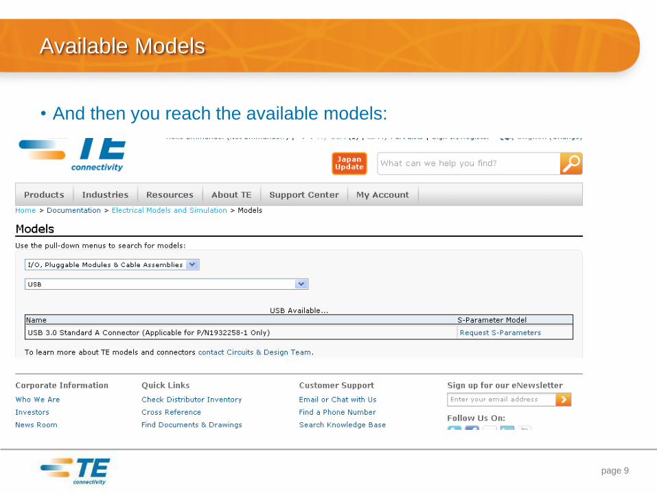
Available Models
• And then you reach the available models:
page 9
•Divider Slide Title Simulation versus Measurement
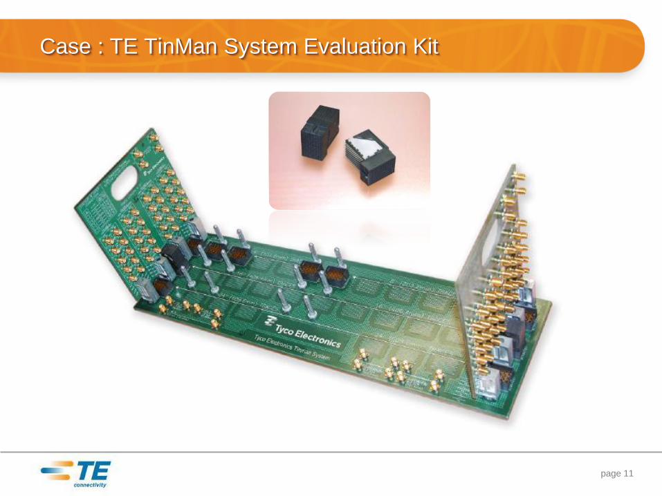
Case : TE TinMan System Evaluation Kit
page 11
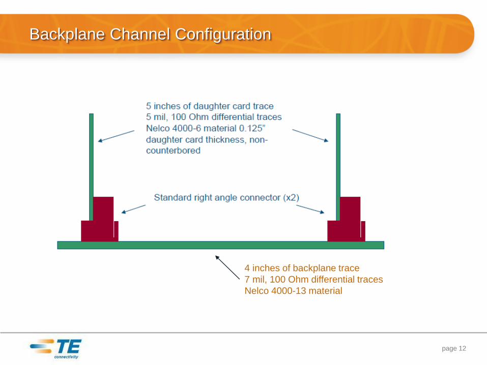
Backplane Channel Configuration
page 12
4 inches of backplane trace
7 mil, 100 Ohm differential traces
Nelco 4000-13 material
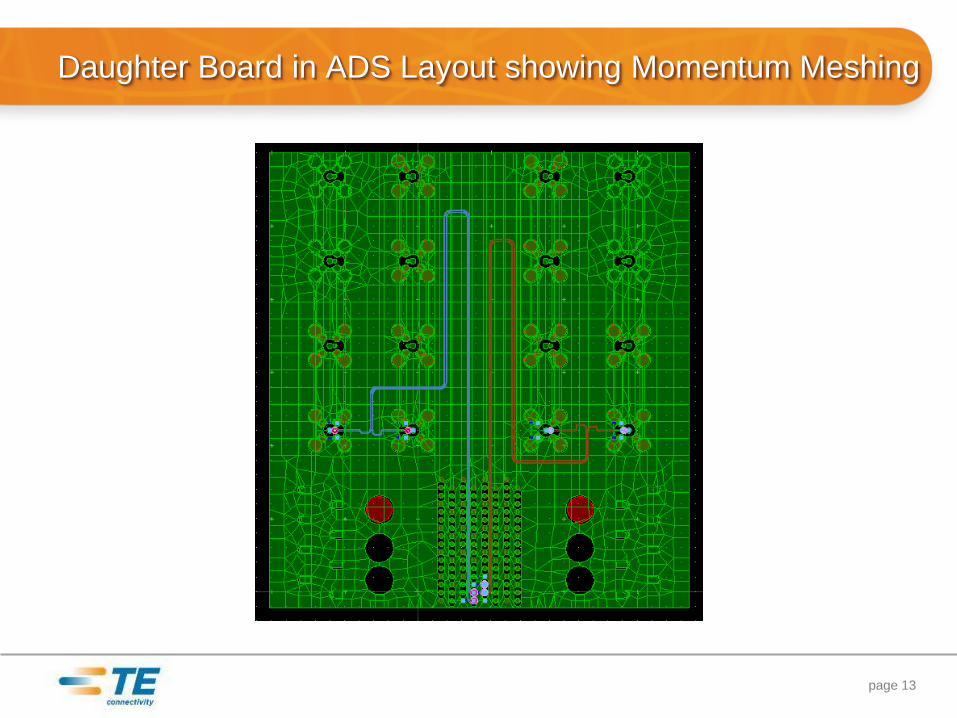
Daughter Board in ADS Layout showing Momentum Meshing
page 13
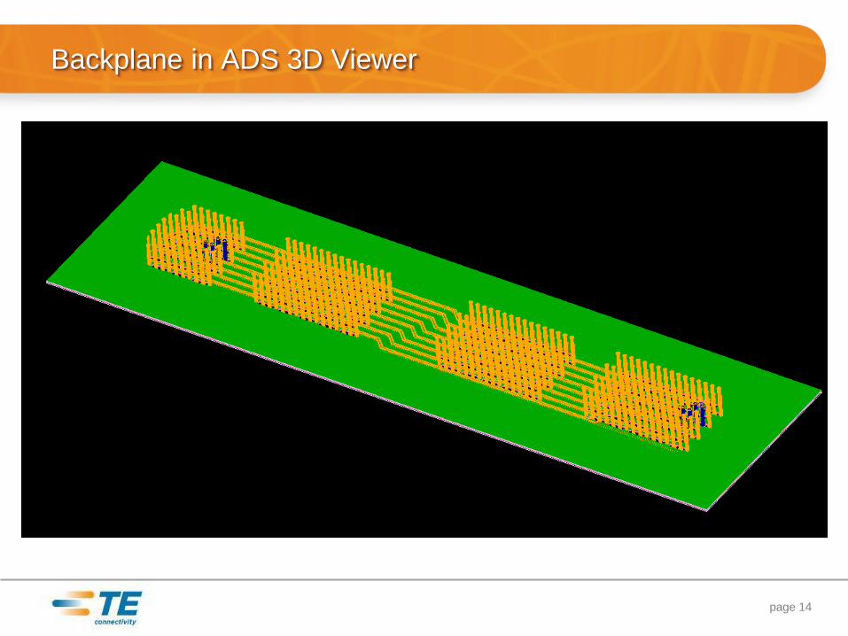
Backplane in ADS 3D Viewer
page 14
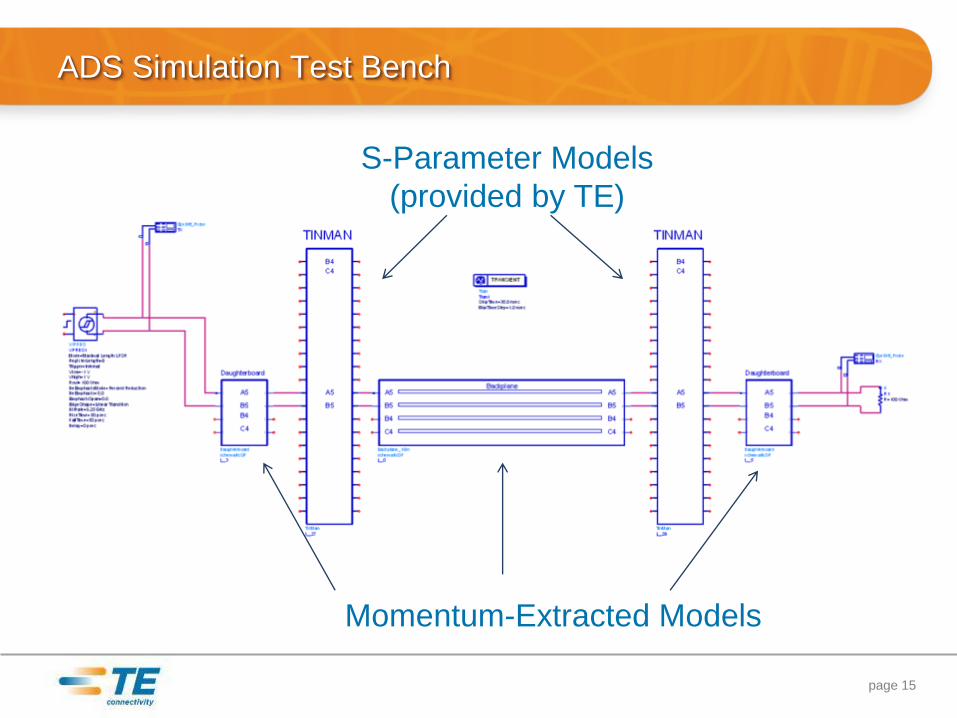
ADS Simulation Test Bench
page 15
Momentum-Extracted Models
S-Parameter Models
(provided by TE)
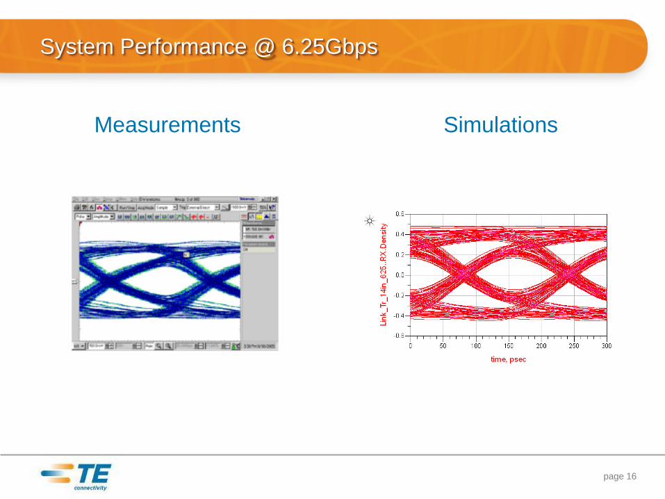
System Performance @ 6.25Gbps
page 16
Measurements Simulations
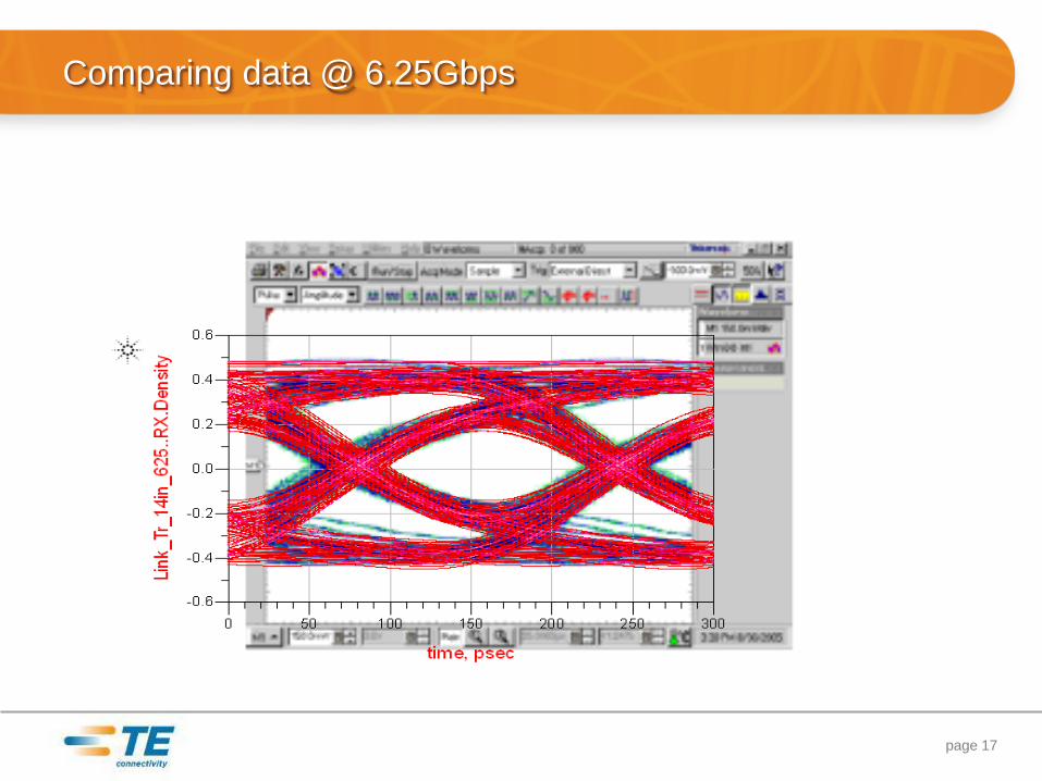
Comparing data @ 6.25Gbps
page 17
Conclusion
• Measurement and simulation are showing equivalent eye opening
• Use of ADS and TE S-parameter models are delivering a reliable
prediction of reality
page 18

•Divider Slide Title Simulation, connector choice and cost optimization
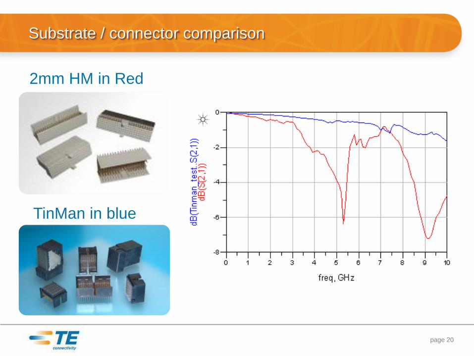
TinMan in blue
Substrate / connector comparison
page 20
2mm HM in Red
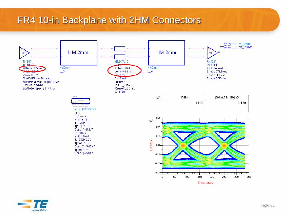
FR4 10-in Backplane with 2HM Connectors
page 21
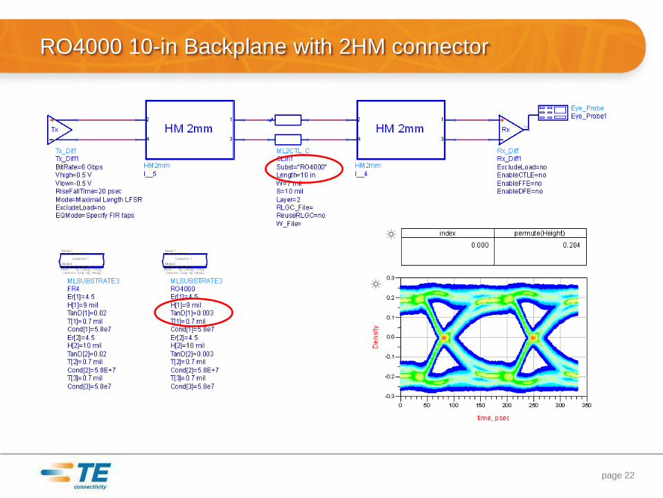
RO4000 10-in Backplane with 2HM connector
page 22
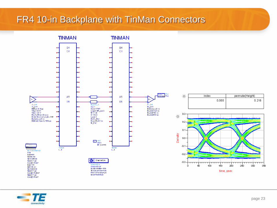
FR4 10-in Backplane with TinMan Connectors
page 23
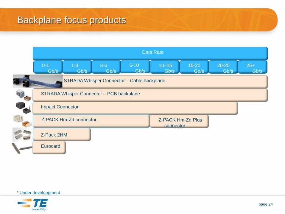
Backplane focus products
page 24
3-6
Gb/s
25+
Gb/s
20-25
Gb/s
15-20
Gb/s
10–15
Gb/s
6-10
Gb/s
STRADA Whisper Connector – Cable backplane
STRADA Whisper Connector – PCB backplane
Impact Connector
Z-PACK Hm-Zd connector Z-PACK Hm-Zd Plus
connector
Data Rate
* Under developpment
Z-Pack 2HM
0-1
Gb/s
1-3
Gb/s
Eurocard
Conclusion
• Using ADS and TE S-parameters models to make the right connector
choice will allow you to push FR4 as far as possible
• Cost of system will be optimized by the simulation of various
connectors with the same PCB material
page 25