Embed Size (px)
Citation preview

K G REMYA et al: SIMULATION STUDIES OF A SLOPE COMPENSATED CURRENT MODE CONTROLLED . .
DOI 10.5013/IJSSST.a.13.04.03 ISSN: 1473 1 -804x online, 1473-8031 print 17
Simulation Studies of a Slope Compensated Current Mode Controlled Boost Converter
K G Remya and Chikku Abraham
Department of Electrical and Electronics Engineering Rajagiri School of Engineering and Technology Kakkanad. e-mails:[email protected],[email protected]
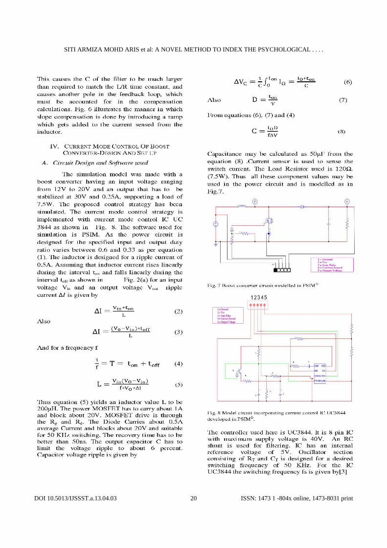
Abstract — This paper discusses the design and simulation of Slope compensated Current mode Controlled Boost converter which is used in several applications like regulated switch mode dc-dc power supplies. There are several types of dc-dc converters. A boost converter simply steps up a source voltage to a higher, regulated voltage. This allows one power supply to provide different voltage levels at different sections in a circuit. The output voltage of boost converter is to be regulated within a specified tolerance band. The control strategy used may be direct duty ratio control, PWM control, voltage feed forward control or current mode control. The current mode control strategy is discussed in this paper wherein the peak inductor current is sensed and used to control the duty ratio of the switches such that the output voltage is regulated within the specified tolerance band. Simulation studies have been carried out on a 7.5 watt boost converter designed with its power circuit and IC UC 3844 is modelled to implement the current mode control of output voltage. The output voltage is maintained at 30V irrespective of the fluctuations in input voltage. An instability is observed at duty ratio’s nearing 0.5 resulting in sub harmonic oscillations. This issue is addressed by proper slope compensation. The entire circuit is designed and modelled using the power electronic software PSIM©. Keywords — Current mode control, Pulse width modulation, Slope compensation, Sub harmonic oscillation
I. INTRODUCTION
DC to DC converters are inevitable in almost all battery powered devices such as laptop computers, mobile phones etc. Voltage Requirements at each section inside these devices differ and these requirements can be satisfied with multiple voltage sources. This issue can be dealt in a better way by using DC to DC converters. Portable electronic devices with multiple batteries increases size and complexity of the device. Another problem associated with usage of battery is the declining voltage of a battery as its stored power is drained, so it does not output a constant voltage level. DC to DC converters thus offer a method of generating multiple controlled voltages from a single battery voltage. This helps in saving space as a single battery is needed instead multiple batteries to supply different parts of the device. DC to DC converters may be of different types such as BUCK converter, BOOST converter or the BUCK BOOST converter. The BOOST converter or the step up converter is the one which is used in regulated dc power supplies and the regenerative braking of dc motors. As the name indicates the output voltage is always greater than input voltage. In dc-dc converters, the average dc output voltage must be controlled to equal a desired level, though the input voltage and the output load may fluctuate. Switch mode dc-dc converters utilize one or more switches to transform dc from one level to another. So the average dc output voltage may be controlled by controlling the ‘on’ period and ‘off’ period of these
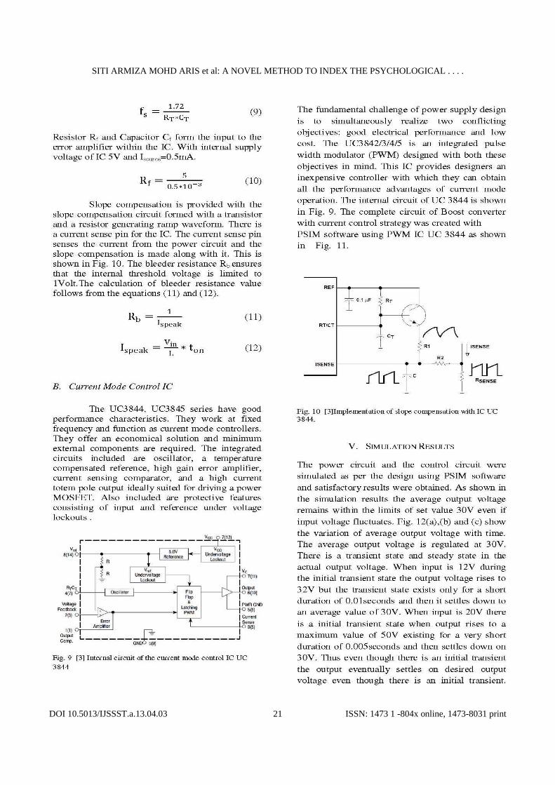
switches. The control strategy used may be direct duty ratio control, PWM control, voltage feed forward control or current mode control. Current mode control is the industry standard method of controlling switching power supplies. A control reference is used to regulate the peak current of the converter directly, simplifying the dynamics of the converter. Here the peak current in the power switch is sensed and turns the switch off at a programmed level of current. The aim of the two approaches is the same and analog circuits were used until recently. Nowadays integrated circuits are available for both voltage mode control and current mode control.
II. BOOST CONVERTER A boost converter is simply is a particular type of power converter with an output DC voltage greater than the input DC voltage. This type of circuit is used to ‘step-up’ a source voltage to a higher, regulated voltage, allowing one power supply to provide different driving voltages. The basic boost converter circuit consists of only a switch (typically a transistor), a diode, an inductor, and a capacitor. The specific connections are shown in Fig. 1. The circuit has two conditions, either the switch may be open or the switch closed. Examining the circuit for two cases (switch open and switch closed) is fairly straight forward, assuming ideal components, and provided that there is constant current flow through the inductor. This case is referred to as ‘continuous

SITI ARMIZA MOHD ARIS et al: A NOVEL METHOD TO INDEX THE PSYCHOLOGICAL . . . .
DOI 10.5013/IJSSST.a.13.04.03 ISSN: 1473 1 -804x online, 1473-8031 print 18

SITI ARMIZA MOHD ARIS et al: A NOVEL METHOD TO INDEX THE PSYCHOLOGICAL . . . .
DOI 10.5013/IJSSST.a.13.04.03 ISSN: 1473 1 -804x online, 1473-8031 print 19
SITI ARMIZA MOHD ARIS et al: A NOVEL METHOD TO INDEX THE PSYCHOLOGICAL . . . .
DOI 10.5013/IJSSST.a.13.04.03 ISSN: 1473 1 -804x online, 1473-8031 print 20
SITI ARMIZA MOHD ARIS et al: A NOVEL METHOD TO INDEX THE PSYCHOLOGICAL . . . .
DOI 10.5013/IJSSST.a.13.04.03 ISSN: 1473 1 -804x online, 1473-8031 print 21

SITI ARMIZA MOHD ARIS et al: A NOVEL METHOD TO INDEX THE PSYCHOLOGICAL . . . .
DOI 10.5013/IJSSST.a.13.04.03 ISSN: 1473 1 -804x online, 1473-8031 print 22

SITI ARMIZA MOHD ARIS et al: A NOVEL METHOD TO INDEX THE PSYCHOLOGICAL . . . .
DOI 10.5013/IJSSST.a.13.04.03 ISSN: 1473 1 -804x online, 1473-8031 print 23
Fig. 13(c) Variation of a section of actual output voltage with time
with slope compensation at duty ratio of 0.3.
Fig. 13 (d) Variation of actual output voltage with time without slope compensation with visible subharmonic oscillations at a
duty ratio of 0.3. Comparison of the results show that subharmonic oscillations or visible disturbances in the output waveform pose a problem in the current mode controlled boost converter circuit without slope compensation. An enlarged view of the output voltage of the circuit without slope compensation is shown in Fig. 13(d). It shows that the output voltages have spikes which are the result of oscillations in the peak current. These oscillations if left unchecked will grow in amplitude with several cycles and may lead to severe problems. As can be seen in Fig. 13(c) these oscillations have been compensated in slope compensated system. Even in a slope compensated systems oscillations do exist but these oscillations are effectively damped out by injecting suitable slope compensation. Thus noise immunity as well as stability of the circuit is improved making the slope compensated current mode controlled boost converter an optimal choice in most applications.
VI. CONCLUSION A 7.5W current mode controlled boost converter was designed simulated successfully. As the simulation results make it clear the current mode control strategy used can keep the output voltage constant at 30V (.25A) inspite of the variations in input voltage. Several performance advantages result from the use of current-mode control. First, an input voltage feed-forward characteristic is
achieved i.e., the control circuit instantaneously corrects for input voltage variations without using up any of the error amplifier's dynamic range. Therefore, line regulation is excellent and the error amplifier can be dedicated to correcting for load variations exclusively. For converters in which inductor current is continuous, controlling peak current is nearly equivalent to controlling average current. The instability phenomenon exists which exists naturally at duty ratio near 0.5 is compensated with the addition of compensating ramp. This method known as slope compensation of current mode controlled boost converter has been discussed in this paper. A current controlled boost converter of this type can have several applications. This converter can be used to increase the efficiency of a battery in what is known as Joule thief ‘circuits’. These may also be used in battery chargers for providing a steady dc voltage to charge the battery. Even a renewable energy source such as the solar panel may use this boost converter circuit at its output to boost the voltage obtained at the output of the solar panel.
REFERENCES [1] Raju.N, Mariappan.V, Jeya prakash.K, Sathya.A, “Teaching Aids
in SMPC Construction Project in the Curriculum of Switched Mode Power Conversion,” published by Department of Electrical Engineering, Indian Institute of Science, Bangalore, 2007.
[2] Ned Mohan, Tore M. Undeland William P. Riobbins, Power Electronics Converters Applications and Design, Wiley, India, 2009, chapter 7.
[3] Unitrode, “UC3842/3/4/5 provides low cost current mode control,” Unitrode Application Note U-100A.
[4] Feng Tian, Siri Kasemsan, and Issa Batarseh, “An Adaptive Slope Compensation for the Single-Stage Inverter with Peak Current-Mode Control,” IEEE Trans. Ind. Electron., vol. 26, no.10, pp.2857-2862,Oct 2011.
[5] Cecil W. Deisch, “Simple Switching Control Method Changes Power Converter into a Current Source,” IEEE Power Electronics Specialists Conference, 1978 Record, pp.300-306 (IEEE Publication 78CH1337-5AES).
[6] Shi-Ping Hsu, Art Brown, Loman Rensink, and R. D. Middlebrook, “Modeling and Analysis of Switching DC-to-DC in Constant-Frequency Current-Programmed Mode,”IEEE Power Electronics Specialists Conference, 1979 Record, pp. 284-301 (IEEE Publication 79CH1461-3 AES).
[7] R. D. Middlebrook and Slobodan Cuk, “A General Unified Approach to Modeling Switching Converter Power Stages,”IEEE Power Electronics Specialists Conference, 1976 Record, pp. 18-34 (IEEE Publication 76CH1084-3 AES); also International J. of Electronics, vol. 42, no. 6, pp. 521- 550, June 1977.
[8] Chris Richardson, “Taming the boost:Predicting and measuring feedback loops in current mode boost high brightness LED drivers, Part 2 of 2,” National semiconductor corporation.
[9] On Semiconductor, “UC 3844/D,” Semiconductor Components Industries, LLC.USA 1999.
[10] L. Dixon, “Average Current Mode Control of Switching Power Supplies,” Unitrode Application Note U-140.
[11] Timothy E. Biesecker, “Current Mode Control,” Venable Industries Venable Technical Paper5.
[12] Dr.Ray Ridley, “A more accurate current mode control model,” published by Ridley Engineering Inc.


![Forereef to Slope Environment [Compatibility Mode]](https://img.pdfslide.us/doc/110x75/577d2d441a28ab4e1ead4976/forereef-to-slope-environment-compatibility-mode.jpg)