Embed Size (px)
Citation preview
Simulation Research of the Matrix Converter Based on Direct Torque Control
Shi Zhang-hai K.W.E.Cheng Department of Electric Engineering, The Hong kong Polytechnic University
Abstract: To advance the performance of AC adjustable
speed system and to reduce the pollution to power network,
this paper proposes a compound control strategy which
combines Matrix Converter (MC) and direct torque control
(DTC). The MC controlled by this strategy cannot only
achieve DTC to a asynchronous machine but also acquire
good input currents and adjustable power factor. The
principle of this strategy is: firstly transform MC into an
equivalent topology that is a combination of a rectifier and
an inverter, and then perform DTC on inverter and current
space vector modulation on the rectifier, at last combine two
sides’ strategies and change them into the control signals of
the MC’s nine bidirectional switches. A simulation about
MC driving asynchronous machine has been done and the
results prove that the strategy proposed by this paper is not
only feasible but also excellent.
Index Terms: matrix converter; direct torque control;
SVPWM
1 Introduction
The pivotal equipment of variable speed system is a frequency converter. At present variable speed system with middle and low power mainly adopts indirect converter (so called AC-DC-AC converter). Traditional indirect converter has a DC link consisted of a large inductance and a large capacitor. The dynamic response is slow and further more the input current of this converter contains a lot of harmonics which make pollutions to the power network and reduce the power factor of the variable system. Matrix converter (MC) overcomes the disadvantages of traditional indirect converter. Without DC energy storage link MC has good dynamic response characteristics. It can also get sinusoidal input current, sinusoidal output voltage and adjustable input displacement factor (IDF).
The early research about MC was focused on two key problems: the implementation and communication of four-quadrant switches (4QSW’s) and the MC control. The former has been solved by combination of two-quadrant switches (2QSW’s) and four step communication method [1]. About the latter, many control algorithms have been put forward. These algorithms can be classified into two kinds: one is direct conversion method, another is indirect conversion method. The most widely used algorithms are space vector modulation (SVPWM) [2] and instantaneous input voltage synthesis method [3]. They are indirect conversion method. These methods aim to acquire expected open-loop sinusoidal output voltage. [4] presents an closed-loop vector control method for MC.
When MC is used to drive and control asynchronous machine, a close-loop control algorithm which combines MC and direct torque control (DTC) can be adopted. The main principle of DTC is to control the torque of motor by keeping the amplitude of stator’s flux linkage and changing the angle between the stator’s flux and rotor’s flux. Compared to the vector control, DTC has its advantages. DTC gets rid of complex math transformation and it is not vulnerable to the impressible rotor’s parameter. This paper presents a compound control strategy which combines Matrix Converter (MC) and direct torque control (DTC) based on SVPWM. The kernel principle of this strategy is as follows. First MC is transformed into an equivalent combination of rectifier and inverter[2]. Then SVPWM is made on the rectifier to acquire the sinusoidal input current and adjustable power factor, DTC is made on the inverter to achieve a high-quality control for motor. The simulation results presented at the last part of this
2006 2nd International Conference on Power Electronics Systems and Applications
199 of 288
paper show that the strategy presented in this paper is feasible.
2 Compound control strategy
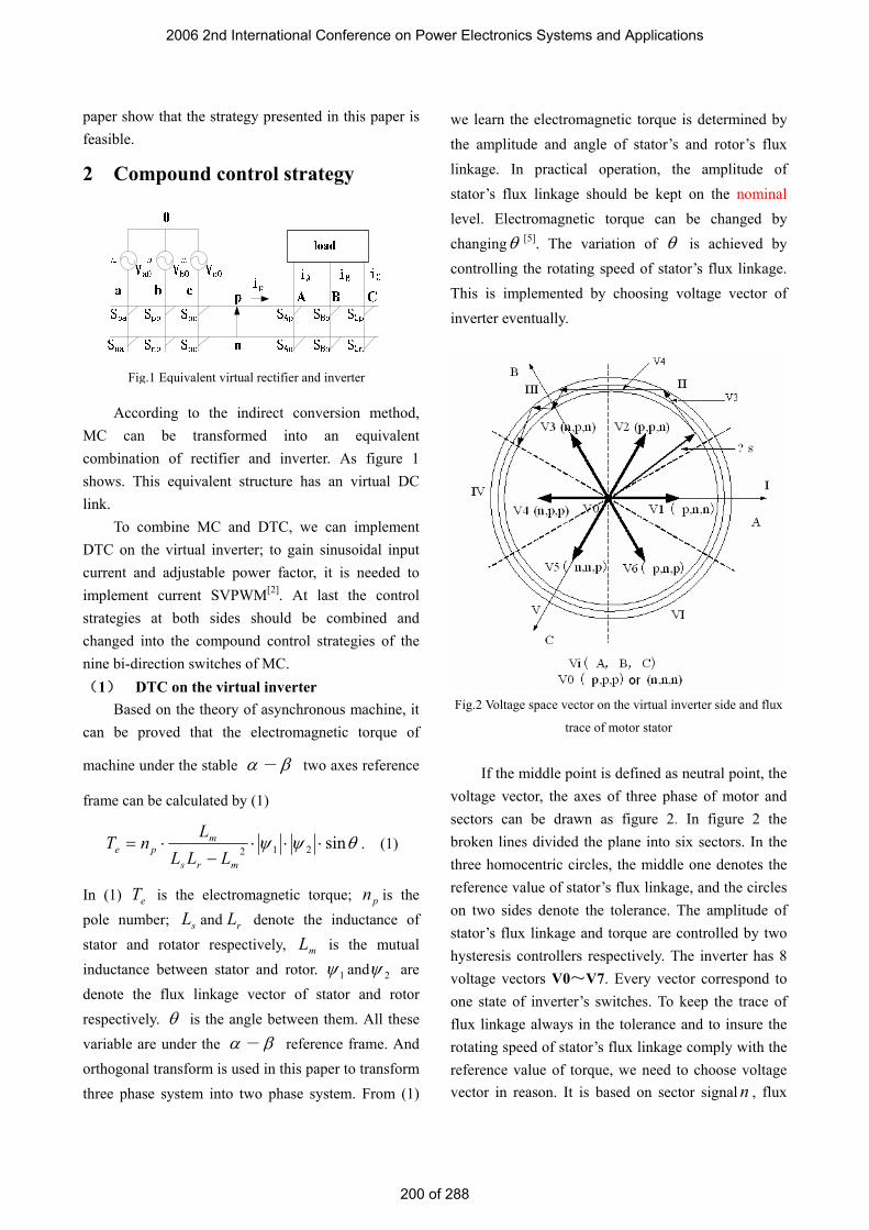
According to the indirect conversion method, MC can be transformed into an equivalent combination of rectifier and inverter. As figure 1 shows. This equivalent structure has an virtual DC link.
To combine MC and DTC, we can implement DTC on the virtual inverter; to gain sinusoidal input current and adjustable power factor, it is needed to implement current SVPWM[2]. At last the control strategies at both sides should be combined and changed into the compound control strategies of the nine bi-direction switches of MC. (1) DTC on the virtual inverter
Based on the theory of asynchronous machine, it can be proved that the electromagnetic torque of
machine under the stable α -β two axes reference
frame can be calculated by (1)
θψψ sin212 ⋅⋅⋅−
⋅=mrs
mpe LLL
LnT . (1)
In (1) eT is the electromagnetic torque; pn is the pole number; sL and rL denote the inductance of stator and rotator respectively, mL is the mutual inductance between stator and rotor. 1ψ and 2ψ are denote the flux linkage vector of stator and rotor respectively. θ is the angle between them. All these variable are under the α - β reference frame. And orthogonal transform is used in this paper to transform three phase system into two phase system. From (1)
we learn the electromagnetic torque is determined by the amplitude and angle of stator’s and rotor’s flux linkage. In practical operation, the amplitude of stator’s flux linkage should be kept on the nominal level. Electromagnetic torque can be changed by changingθ [5]. The variation of θ is achieved by controlling the rotating speed of stator’s flux linkage. This is implemented by choosing voltage vector of inverter eventually.
Fig.2 Voltage space vector on the virtual inverter side and flux
trace of motor stator
If the middle point is defined as neutral point, the
voltage vector, the axes of three phase of motor and sectors can be drawn as figure 2. In figure 2 the broken lines divided the plane into six sectors. In the three homocentric circles, the middle one denotes the reference value of stator’s flux linkage, and the circles on two sides denote the tolerance. The amplitude of stator’s flux linkage and torque are controlled by two hysteresis controllers respectively. The inverter has 8 voltage vectors V0~V7. Every vector correspond to one state of inverter’s switches. To keep the trace of flux linkage always in the tolerance and to insure the rotating speed of stator’s flux linkage comply with the reference value of torque, we need to choose voltage vector in reason. It is based on sector signal n , flux
Fig.1 Equivalent virtual rectifier and inverter
2006 2nd International Conference on Power Electronics Systems and Applications
200 of 288

linkage error signal ψΔ and torque error signal
TΔ to choose the optimal voltage vector. For example, at a particular instant, the output voltage
vector is in the first sector, if 0>Δψ , then the actual
flux linkage is smaller than the reference value and needed to increase. According to figure 2 two vectors can make the flux linkage increase. They are V2 and V6. If 0>ΔT meanwhile, that means the actual torque need be increased, then we can only choose vector V2 because only V2 can increase the rotating speed so as to increase the torque. Inversely if
0<ΔT , only V6 can be chose. To reduce the frequency of switches, the torque hysteresis controller can be improved into a three-level comparator (see
figure 3). It’s principle is as follow: if μ>ΔT (μ
is torque tolerance), then increase torque; if
μ−<ΔT , then reduce torque; if μμ <Δ<− T ,
then keep the stator’s flux linkage stable by choosing zero vector V0 or V7.
Stator's flux linkage observation
model
Sector determin
a-tion
Ψs
Ψs reference
Torque detectorΨ×i
T reference
ΔΨs
ΔTTµ
-µ
decoder
PWM signal Virtual
inverter
is
PIregulator
ω reference
+-
+
-
+
-ω
Voltage vector
selector
Fig.3 principle diagram of direct torque control
on the virtual inverter side
Figure 3 is the block diagram of the principle of DTC on inverter side. To control the stator’s flux linkage, estimate of torque and flux linkage is needed. About the estimation techniques Ref [5] presents many useful methods. In figure 3 the sector can be decided by the following method. First project the stator’s flux linkage sψ to the three phase axes to get three components Aψ , Bψ , Cψ . Then examine three components’ polarity. Sector’s serial number can be
decided by these polarities. For example, if three components’ polarities are +,-,-, then sψ is in sector 1 according to figure 2. The rest may be deduced by analogy.
(2) Current SVPWM on rectifier
Fig.4 Current space vector and hexagon sector
The rectifier’s current space vectors are shown as
figure 4. There are six non-zero current vectors I1~I6 and three different zero current vector denoted by I0. These vectors can be produced by rectifier directly and called switching state vectors (SSV’s). The principle of current space vector modulation is to insert more current vectors in every sector so as to make the input current be more close to symmetrical sine wave. These inserted vectors can be synthesized by two adjacent SSV’s and zero vectors according the synthesis principle of vector. [2] describes the principle of current SVPWM in detail. (3) Compound control strategy
The current modulation on rectifier and DTC on inverter should be combined to form the control strategy of nine switches of MC. Each current vector I of rectifier and each voltage vector V of inverter can be combined to form an I-V pair. Each I-V pair correspond to only one state of MC’s switches. Compound control can be implemented as follows. At each sample instant, execute the current SVPWM on virtual rectifier to choose the current vector Ii, execute DTC on virtual inverter to choose voltage vector Vj, then combine them to form vector pair Ii-Vj, at last
2006 2nd International Conference on Power Electronics Systems and Applications
201 of 288

decode the vector pair Ii-Vj to get the PWM signals of nine switches of MC. For example, the selected vector of rectifier and inverter are I1 and V1 respectively. Then the combined vector pair is I1-V1. I1 correspond to the rectifier’s state that Spa and Snc are closed and the others are open (see figure 1 and 4). V1 correspond to the inverter’s state that SAp, SBn and SCn
are closed and the others are open. Combining the switches’ states on both side and making a transformation, we get the MC’s state corresponding
to vector pair I1-V1. That is SaA, ScB and ScC are closed and the others are open. The corresponding relationship between vector pair and switches’ state of MC can be transformed into table and put into micro processor. Micro processor looks into this table and decodes it to produce the PWM signal of nine switches of MC.
Figure 5 is the block diagram of combined
controller. iϕ is input power factor angle. It can be
set arbitrarily. m is modulation index ( 10 ≤< m ).
It influences pnv that is the voltage of virtual middle
DC link. The relationship between them is
iimpn Vmv ϕcos23
×××= [2]. To maximize the
voltage of virtual middle DC link m can be set to unit. *ω and *
sψ are the reference value of rotating
speed and amplitude of stator’s flux linkage
respectively. This combined controller as figure 5
shows can be implemented by DSP.
3 Simulation result
Based on the strategy above, the author use software Simulink of Matlab 7.0 to conduct a simulation. The simulation block diagram is shown in figure 5. The parameters of motor are as follows: Pn=
4kW, VL=400V, n=1430rpm, fn=50Hz, Rs=1.045Ω, Rr=1.395Ω, Ls=178.039mH, Lr=178.039mH, Lm=
172.2mH, J=0.0131kg·m2, Pole=2. The inductances above are all the equivalent inductance of motor’s model under the α - β two stable axes reference frame. In the simulation course, ideal bi-direction switch is used as the main switches of MC. Fix-step four order Runge-Kutta method is used. The step is
0.05ms. The PI controller’s parameter of rotate speed is: P=0.8, I=5. The input phase voltage of MC is 270V. The input power factor is set to unit. The amplitude of stator’s flux linkage is kept on 1.2 Wb.
Figure 6 is the dynamic response waveform when motor’s rotate speed varies. The rotate speed command is 900 rpm→1200 rpm→900 rpm. In the simulation course, keep the load torque on 20N·m that is 75%rating torque. In the figure rω is the rotator’s speed, Te is electromagnetic torque, isa is the current of phase a of stator. According to the figure, the dynamic response of rotate speed is rapid without overshoot. Response time of the system with load is not more than 0.3 second. Electromagnetic torque is
V i Sector
Determi-
nation
Current vectorselector on
rectifier sideTime
calculator
nt
De-
coder
Matrix
converter
M
is
∗ ω ∗ s ψ
i ϕ
m
Rotate
speed
sensor
Ii
V j
Ii -- V j
Fig.5 Combinated controller block
Voltage vectorselector on
inverter side
ω
2006 2nd International Conference on Power Electronics Systems and Applications
202 of 288

calm enough. Stator’s current can enter into steady state rapidly. Start current of the motor with load is small enough, about 3~4 times bigger than rating current.
Figure 7 is the dynamic response waveform of the system when the load is sudden changed. The variation of load torque is: 7 N·m(25%TN)→ 20 N·m (75%TN)→ 7 N·m(25%TN. In simulation course the command of rotate speed is kept on 900 rpm. From the figure we can see that: when the load torque varies, the fluctuation is small, output electromagnetic torque can track the load torque rapidly.
Figure 8 is the wave form and frenquency
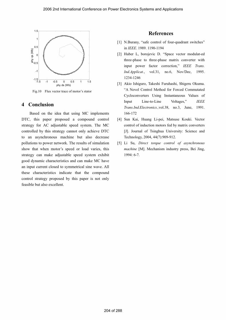
spectrum of current of MC’s input phase a. In simulation course keep rotate speed command on 900 rpm, load torque on 20N·m. From the figure we can see that: fundamental component is the main part in input current. There are also some high frequency harmonics. They can be easily filtered by adding a small filter. Figure 9 is the fundamental component’s angle of the current of input phase a. the figure clearly shows that the input power factor can be reach 1. Figure 8 and indicate that the wave form of input current is very good and will cause little pollution to power network. Figure 10 is the trace plot of stator’s flux linkage of motor. This circular plot corresponds to the demand of DTC.
Fig.9 Fundamental wave’s angle of input
phase a current
0 0.2 0.4 0.6 0.8 1-100
0
100
t (s)
angl
e (d
egre
e)
Fig.8 Waveform and spectrum of
input phase a current
0.6 0.7 0.8 0.9 1-20
0
20
t (s)
ia (A
)
050 200 400 600 800 10000
1
2
33.5
f (Hz)
Am
plitu
de (A
)
0.2 0.4 0.6 0.8 1700
900
1100
wr (
rpm
)
0.2 0.4 0.6 0.8 107
2030
Te (N
m)
0.2 0.4 0.6 0.8 1
-100
10
t (s)
isa
(A)
Fig.7 Dynamic response waveform under
the variation of load
0 0.2 0.4 0.6 0.8 1-50
0
50
t (s)
isa
(A)
0 0.2 0.4 0.6 0.8 10
300600900
1200
wr (
rpm
)
0 0.2 0.4 0.6 0.8 1-20
02040
80
Te (N
m)
Fig.6 Dynamic response waveform under
the variation of rotation speed
2006 2nd International Conference on Power Electronics Systems and Applications
203 of 288
4 Conclusion Based on the idea that using MC implements
DTC, this paper proposed a compound control strategy for AC adjustable speed system. The MC controlled by this strategy cannot only achieve DTC to an asynchronous machine but also decrease pollutions to power network. The results of simulation show that when motor’s speed or load varies, this strategy can make adjustable speed system exhibit good dynamic characteristics and can make MC have an input current closed to symmetrical sine wave. All these characteristics indicate that the compound control strategy proposed by this paper is not only feasible but also excellent.
References [1] N.Burany, “safe control of four-quadrant switches”
in IEEE. 1989. 1190-1194 [2] Huber L, borojevic D. “Space vector modulat-ed
three-phase to three-phase matrix converter with input power factor correction,” IEEE Trans. Ind.Applicat., vol.31, no.6, Nov/Dec, 1995. 1234-1246
[3] Akio Ishiguro, Takeshi Furuhashi, Shigeru Okuma. “A Novel Control Method for Forced Commutated Cycloconverters Using Instantaneous Values of Input Line-to-Line Voltages,” IEEE Trans.Ind.Electronics.,vol.38, no.3, June, 1991. 166-172
[4] Sun Kai, Huang Li-pei, Matsuse Kouki. Vector control of induction motors fed by matrix converters [J]. Journal of Tsinghua University: Science and Technology, 2004, 44(7):909-912.
[5] Li Su, Direct torque control of asynchronous machine [M]. Mechanism industry press, Bei Jing, 1994: 6-7.
Fig.10 Flux vector trace of motor’s stator
-1.5 -1 -0.5 0 0.5 1 1.5-1.5
-1
-0.5
0
0.5
1
1.5
phy ds (Wb)
phy
qs (W
b)
2006 2nd International Conference on Power Electronics Systems and Applications
204 of 288