Embed Size (px)
Citation preview
i
SIMULATION OF TURKISH LIP MOTION AND FACIAL EXPRESSIONS IN A 3D ENVIRONMENT AND SYNCHRONIZATION WITH A TURKISH SPEECH
ENGINE
A THESIS SUBMITTED TO THE GRADUATE SCHOOL OF NATURAL AND APPLIED SCIENCES
OF THE MIDDLE EAST TECHNICAL UNIVERSITY
BY
ERDEM AKAGÜNDÜZ
IN PARTIAL FULFILMENT OF THE REQUIREMENTS FOR THE DEGREE OF MASTER OF SCIENCE
IN THE DEPARTMENT OF ELECTRICAL AND ELECTRONICS ENGINEERING
JANUARY 2004
ii
Approval of the Graduate School of Natural and Applied Sciences
____________________
Prof. Dr. Canan Özgen
Director
I certify that this thesis satisfies all the requirements as a thesis for the degree of Master of Science.
____________________
Prof. Dr. Mübeccel Demirekler
Head of Department
This is to certify that we have read this thesis and that in our opinion it is fully adequate, in scope and quality, as a thesis for the degree of Master of Science.
_____________________ ___________________
Prof. Dr. Kemal Leblebicio�lu Prof. Dr. U�ur Halıcı
Co- Supervisor Supervisor
Examining Committee Members
Prof. Dr. Kemal Leblebicio�lu ____________________
Prof. Dr. U�ur Halıcı ____________________
Assoc. Prof. Dr. Nazife BAYKAL ____________________
Asst. Prof. Dr. Cüneyt F. Bazlamaçcı ____________________
Dr. �lkay Ulusoy ____________________
Prof. Dr. Kemal Leblebicio�lu Co- Supervisor
Prof. Dr. U�ur Halıcı Supervisor
Prof. Dr. Canan Özgen
Director
Prof. Dr. Mübeccel Demirekler
Head of Department
iii
ABSTRACT
SIMULATION OF TURKISH LIP MOTION AND FACIAL EXPRESSIONS IN A
3D ENVIRONMENT AND SYNCHRONIZATION WITH A TURKISH SPEECH
ENGINE
Akagündüz, Erdem
M.Sc., Deparment of Electrical and Electronics Engineering
Supervisor: Prof. Dr. U�ur Halıcı
January 2004, 100 pages
In this thesis, 3D animation of human facial expressions and lip motion and their
synchronization with a Turkish Speech engine using JAVA programming language,
JAVA3D API and Java Speech API, is analyzed. A three-dimensional animation
model for simulating Turkish lip motion and facial expressions is developed.
In addition to lip motion, synchronization with a Turkish speech engine is achieved.
The output of the study is facial expressions and Turkish lip motion synchronized
with Turkish speech, where the input is Turkish text in Java Speech Markup
Language (JSML) format, also indicating expressions.
Unlike many other languages, in Turkish, words are easily broken up into syllables.
This property of Turkish Language lets us use a simple method to map letters to
Turkish visual phonemes. In this method, totally 37 face models are used to represent
iv
the Turkish visual phonemes and these letters are mapped to 3D facial models
considering the syllable structures.
The animation is created using JAVA3D API. 3D facial models corresponding to
different lip positions of the same person are morphed to each other to construct the
animation.
Moreover, simulations of human facial expressions of emotions are created within
the animation. Expression weight parameter, which states the weight of the given
expression, is introduced.
The synchronization of lip motion with Turkish speech is achieved via
CloudGarden®’s Java Speech API interface.
As a final point a virtual Turkish speaker with facial expression of emotions is
created for JAVA3D animation.
Keywords: 3D facial modeling, facial animation, lip motion, lip/speech
synchronization, facial expression simulation.
v
ÖZ
TÜRKÇE DUDAK HAREKETLER�N�N ve YÜZ �FADELER�N�N 3 BOYUTLU
ORTAMDA BENZET�M� VE B�R TÜRKÇE SES MAK�NASIYLA E� ZAMANLI
HALE GET�R�LMES�
Akagündüz, Erdem
Yüksek Lisans, Elektrik Elektronik Mühendisli�i Bölümü
Tez Yöneticisi: Prof. Dr. U�ur Halıcı
Ocak 2004, 100 sayfa
Bu tezde, Türkçe dudak hareketlerinin ve yüz ifadelerinin 3 boyutlu ortamda
canlandırılması ve bir türkçe ses makinasıyla e� zamanlanması üzerinde çalı�ılmı�tır.
Bu çalı�mada Java programlama dili, JAVA3D 3 boyutlu ortam kütüphanesi ve Java
Speech API ara birimini kullanılmı�tır. Türkçe dudak hareketlerini ve yüz ifadelerini
canladıran, 3 boyutlu bir bezetim modeli geli�tirilmi�tir.
Dudak hareketlerine ek olarak, bir Türkçe ses makinası kullanılarak dudak
hareketleri ve Tükçe konu�ma e� zamanlı hale getirilmi�tir. Çalı�manın çıktısı yüz
ifadeleriyle birle�tirilmi� e� zamanlı Türkçe dudak hareketi ve Türkçe konu�ma olup,
girdisi yüz ifadelerini de betimleyen Java Konu�ma Modelleme Dili (JSML)
yapısında Türkçe metin olmaktadır.
Di�er birçok dilden farklı olarak, Türkçe’de kelimeler kolayca hecelerine
ayrılmaktadır. Türkçenin bu özelli�i, Türkçe konu�ma yüz modellerini Türkçe yazılı
vi
metine basit bir yöntemle e�le�tirmemizi sa�lamı�tır. Bu yöntemde Türkçe dudak
hareketlerini temsil etmek için toplam 37 Türkçe konu�ma yüz modeli kullanılmı� ve
bu e�le�tirme i�lemi sırasında hece yapıları göz önünde bulundurulmu�tur.
Canlandırma JAVA3D API kullanılarak olu�turulmu�tur. Aynı ki�iye ait de�i�ik
dudak hareketlerine kar�ılık gelen yüz modelleri birbirlerine morf edilerek
canlandırma olu�turulmu�tur.
Ayrıca, canlandırmanın içinde duygusal yüz ifadelerinin benzetimi yapılmı�tır. Bir
yüz ifadesinin ne kadar a�ırlıkta verildi�ini temsil eden ifade a�ırlı�ı parametresi
tanımlanmı�tır.
CloudGarden® �irketinin Java Speech API ara birimi kullanılarak Türkçe ses
makinası dudak hareketleri ile e�zamanlı hale getirilmi�tir.
Son olarak Türkçe dudak hareketlerini ve duygusal yüz ifadelerinin benzetimini
yapan bir sanal Türkçe konu�macı, JAVA3D canlandırmasında olu�turulmu�tur.
Anahtar Kelimeler: 3 Boyutlu nesne morfu, insan yüzü canlandırması, dudak
hareketleri, dudak/ses e�zamanlaması, yüz ifadelerinin benzetimi.

vii
To My Father and My Mother
viii
ACKNOWLEDGMENTS
This thesis has been conducted in Computer Vision and Intelligent Systems Research
Laboratory in Electrical and Electronics Department and has been partly supported in
project BAP-2002-07-04-04.
I am thankful to my advisor and Supervisor Prof. Dr. U�ur Halıcı for her guidance
and assistance during my M.Sc. study.
I would also like to thank Prof. Dr. Kemal Leblebicio�lu and everybody from METU
Computer Vision and Intelligent Systems Research Laboratory for their technical
advices and friendship.
I would also like to thank Dr. Levent Arslan from Bo�aziçi University and GVZ
Speech Technologies Software Company for providing their speech engine system
for academic usage.
ix
TABLE OF CONTENTS
ABSTRACT .......................................................................................................... iii
ÖZ ............................................................................................................................v
DEDICATION ..................................................................................................... vii
ACKNOWLEDGMENTS................................................................................... viii
TABLE OF CONTENTS.......................................................................................ix
THE LIST OF TABLES...................................................................................... xii
THE LIST OF FIGURES................................................................................... xiii
CHAPTER
1 INTRODUCTION................................................................................................1
1.1 Motivation......................................................................................................1
1.2 Related Studies..............................................................................................2
1.3 Problem Definition ........................................................................................4
1.4 The Study.......................................................................................................4
2 HUMAN FACIAL SYSTEM ...............................................................................6
2.1 Human Face Anatomy...................................................................................6
2.1.1 Facial Skeleton ........................................................................................7
2.1.1.1 The Mandible.................................................................................10
2.1.2 Facial Muscles.......................................................................................12
2.1.2.1 The Muscles of the Face.................................................................14
2.1.2.1.1 Circum-orbital Muscles of the Eye.........................................15
2.1.2.1.2 Muscles of the Nose.................................................................15
2.1.2.1.3 Muscles of the Mouth ..............................................................15
x
2.1.2.1.4 The Muscles of Mandible and Mastication ............................17
2.2 Structure And Dynamics Of Human Facial Expressions...........................18
2.2.1 Universal Facial Expressions................................................................19
3 TURKISH SPEECH AND LIP MOTION ........................................................27
3.1 Vocal and Structural Properties of Turkish Language..............................27
3.2 L ip Motion in Turkish Language ...............................................................28
3.2.1 Turkish Visual Phonemes.....................................................................29
4 3D VIRTUAL SYSTEMS, 3D FACIAL MODELS AND 3D FACIAL
EXPRESSIONS.....................................................................................................37
4.1 3D Virtual Systems......................................................................................37
4.2 3D Facial Models.........................................................................................38
4.2.1 Volume Representations.......................................................................38
4.2.2 Surface Representations.......................................................................40
4.2.3 Polygonal Representations ...................................................................42
4.3 Simulation of 3D Facial Expressions ..........................................................46
5 SIMULATION AND SYNCHRONIZATION OF TURKISH LIP MOTION
IN A 3D ENVIRONMENT WITH A TURKISH SPEECH ENGINE ................50
5.1 3D Weighted Morphing...............................................................................50
5.1.1 Mapping Turkish visual phonemes to Turkish letters. .......................55
5.2 3D Weighted Morphing Simulation of Turkish L ip Motion And Facial
Expressions........................................................................................................58
5.2.1 The Method...........................................................................................58
5.2.2 Extraction of Turkish Syllables............................................................59
5.2.3 Mapping of the letters to 3D models. ...................................................61
5.2.4 Morphing of the Facial Expressions.....................................................63
5.2.5 Speech Markup Language Implementation ........................................65
5.3 Turkish L ip Motion-Speech Synchronization ............................................67
5.3.1 Synchronization with GVZ Speech SDK .............................................68
6 RESULTS AND PERFORMANCE ..................................................................71
6.1 L ip/Speech Synchronization........................................................................72
6.2 Number of frames / second..........................................................................73
6.3 Synthesized Sound Quality..........................................................................73
xi
6.4 Software Performance.................................................................................74
6.5 3D Esthetic model and animation quality...................................................75
7 CONCLUSIONS AND FUTURE STUDIES.....................................................76
REFERENCES......................................................................................................78
APPENDIX
A DETAILS OF THE SIMULATION SOFTWARE ..........................................80
B TURKISH VISUAL PHONEMES....................................................................86
C SAMPLE SIMULATONS.................................................................................99
xii
THE LIST OF TABLES
Table 5.1 Turkish letters mapped to Turkish Visual Phonemes. ........................56
Table 5.2 Sentence ‘Merhaba, benim adım Erdem.’ visual phoneme mapping .63
Table 5.3 JSML Emotion tags..............................................................................66
Table 5.4 Turkish phones and their mean durations...........................................68
xiii
THE LIST OF FIGURES
Figure 2.1 The Cranium and the Facial Skeleton ..................................................7
Figure 2.2 Facial Bones...........................................................................................9
Figure 2.3 The Lateral view of the Skull ..............................................................10
Figure 2.4 The Mandible.......................................................................................11
Figure 2.5 Facial Muscles......................................................................................13
Figure 2.6 Lateral view of the Facial Muscles......................................................16
Figure 2.7 Surprise and Surprise blended with happiness. .................................21
Figure 2.8 Fear blended with surprise. ................................................................22
Figure 2.9 Disgust..................................................................................................23
Figure 2.10 Anger blended with sadness. .............................................................24
Figure 2.11 Happiness...........................................................................................25
Figure 2.12 Sadness...............................................................................................26
Figure 3.1 Visual Phoneme “ c” .............................................................................31
Figure 3.2 Visual Phoneme “ f” .............................................................................32
Figure 3.3 Visual Phoneme “ i” .............................................................................33
Figure 3.4 Visual Phoneme “ m” ...........................................................................34
Figure 3.5 Visual Phoneme “ o” ............................................................................35
Figure 4.1 3D virtual Scene including 3D objects................................................38
Figure 4.2 3D Voxel Representation.....................................................................39
Figure 4.3 Beizer Control Points and Bezier Sur face Patch................................42
Figure 4.4 A Polygonal Mesh................................................................................43
Figure 4.5 Cube rendered with color properties..................................................44
Figure 4.6 Cube rendered with texture................................................................45
xiv
Figure 4.7 Facial Polygonal Meshes.....................................................................46
Figure 4.8 Key-frame animation ..........................................................................48
Figure 5.1 Weighted Morphing ............................................................................51
Figure 5.2 Neutral Face Model, N ........................................................................53
Figure 5.3 Emotion model for “ Anger” , E ...........................................................53
Figure 5.4 Empowered Emotion Model “ Anger” , P............................................54
Figure 5.5 Different Visual Phonemes for the letter “ m” in different syllables..62
Figure 5.6 The position of the simulation of the sentence in Table 5.2 ...............64
Figure 5.7 Audio Signal of “ Merhaba” sound Sequence. ....................................67
Figure A.1 Software Implementation...................................................................81
Figure A.2 Software Implementation – PART I - PARSING..............................82
Figure A.1 Software Implementation – PART I I – ANALYSIS & SYNTHESIS
...............................................................................................................................84
1
CHAPTER 1
INTRODUCTION
1.1 Motivation
Communication is possibly the most important evolution of human kind. All other
capabilities, developments, technologies created by our civilization were put together
by this ability. Without a shred of doubt, modern world brought its new modern
communication types. 80 years ago it was radio, 50 years ago it was television, just
10 years ago it was Internet and in near future it will become virtual character
communication.
We as humans, communicate using our entire body. We use our face, our voice, our
body, and our social states to communicate. But among all of these communication
gifts, human face and human voice are the most fundamental ones. Essentially, the
face is the part of the body we use to recognize the individuals; we can recognize a
face from vast universe of similar faces and are able to detect very subtle changes in
facial expression [Parke, Waters 1996]. These skills are learned early in life, and they
rapidly develop into a major channel of communication. Actually that’s why
animators pay a great deal of attention to the face.
In recent years there has been considerable interest in computer-based three-
dimensional facial character animation [Parke, Waters 1996]. These studies go back
more than 30 years. However with the rapid growth of hardware and software
computer technologies during the recent years, the outputs of these studies became
2
more evident. Facial animation, facial expression animation, lip motion for languages
and lip/speech synchronization are some of the important applications.
Among these studies we found out that there has not been a total study on lip motion
and lip/synchronization for Turkish language. For this reason we have decided to
construct a system for Turkish lip motion animation, and lip/speech synchronization.
Naturally we have decided to use 3D virtual environment to build up this system.
The reason why we have chosen 3D environment is that we felt urgent need to catch
up the state of the art technologies in computer-based three-dimensional facial
character animation.
1.2 Related Studies
The difficulty of the modeling of human facial motion is mainly due to the
complexity of the physical structure of the human face. Not only are there a great
number of specific bones, but there is also interaction between muscles and bones
and between the muscles themselves [Kalra, 1991]. Human facial expressions have
been the subject of much investigation by scientific community. For more than 30
years researchers studied on creating models representing expressions and lip
motion. Some milestone studies are listed below.
Long ago in 1872, Charles Darwin published “The Expression of the Emotions in
Man and Animals, where he dealt precisely with these issues. Actually this was the
very start of the studies that led us to today’s technology in character animation.
In 1972 Frederic I. Parke began with a very crude polygonal representation of the
head, which resulted in a flip-pack animation of the face opening and closing eyes
and mouth [Parke, Waters 1996].
In 1975 Paul Ekman stated that humans are highly sensitive to visual messages sent
voluntarily or involuntarily by the face. Consequently, facial animation requires
specific algorithms able to render the natural characteristics of the motion with a high
degree of realism. Research on basic facial animation and modeling has been
extensively studied and several models have been proposed [Ekman 1975].
Later, Platt and Badler have designed a model that is based on underlying facial
structure. The skin is the outside level, represented by a set of 3D points that define a
surface, which can be modified. The bones represent an initial level that cannot be
3
moved. Between both levels, muscles are groups of points with elastic arcs [Platt,
Badler 1981].
Waters in 1987 represented the action of muscles using primary motivators on a non-
specific deformable topology of the face. Two types of muscle were created:
linear/parallel muscles that pull and sphincter muscles that squeeze [Waters 1987].
Magnenat-Thalmann et al. defined a model where the action of a muscle is simulated
by a procedure, called Abstract Muscle Action procedure (AMA), which acts on the
vertices composing the human face figure. It is possible to animate a human face by
manipulating the facial parameters using AMA procedures. By combining the facial
parameters obtained by the AMA procedures in different ways, we can construct
more complex entities corresponding to the well-known concept of facial expression
[Magnetat- Thalmann N. 1988].
In 1991 Prem Kalra, Angelo Mangili et al. introduced SMILE: A multilayered facial
animation system. They described a methodology for specifying facial animation
based on a multi-layered approach. Each successive layer defines entities from a
more abstract point of view, starting with phonemes, and working up through words,
sentences, expressions, and emotions. Finally, the high level allows the manipulation
of these entities, ensuring synchronization of the eye motion with emotions and word
flow of a sentence [Kalra 1991].
In 1994, the first version of VRML, virtual reality modeling language was presented.
The lack of animation and interaction was leading to VRML 2.0 that became the ISO
standard VRML-97 [VRML2.0 1996]. In succeeding years VRML-97 was added to
the MPEG-4 standard which is an ISO/IEC standard developed by MPEG (Moving
Picture Experts Group), the committee that also developed the Emmy Award
winning standards known as MPEG-1 and MPEG-2. Specific extensions were related
to the animation of artificial faces and bodies. The facial animation object in MPEG-
4 can be used to render an animated face. Face animation in MPEG-4 provides for
highly efficient coding of animation parameters that can drive an unlimited range of
face models [MPEG-4 1998].
Other than these studies several 3D facial geometry representation techniques were
introduced and are still being introduced.
4
1.3 Problem Definition
In this thesis, a three-dimensional character face with lip motion of Turkish language
and facial expressions synchronized with real-time synthesized speech is aimed.
Moreover, a system with text as input and an animation as output is proposed. A
software animation system with adequate animation quality aspects is intended.
Furthermore the system to be constructed should be flexible in model and voice
selection. Plainly a three-dimensional character animation system compatible to
different facial models and different voices is meant. So the overall system is
expected to be working well in Turkish lip motion, facial expressions and lip/speech
synchronization for these different sets of facial models and synthetic voices.
In addition, to realize a simulation study like this, the structural properties of Turkish
should be totally examined. Like every language Turkish has some syntactic
properties and by this study these properties should be utterly parsed in our
implementation system.
Besides visual animation system, a vocal synthesis system is required. As the system
is intended to be a “text to speech and animation” system, real-time Turkish speech
synthesis is obligatory. Additionally a system to synchronize this speech synthesis
system with animation system must be defined and constructed.
1.4 The Study
The steps we have taken in order to fulfill the requirements of this well-defined
problem, are written below.
In Chapter 2 human facial system is analyzed. Starting with the anatomical structure
of the human skull, we have studied the facial bones and muscles. After
understanding the structural properties of human facial anatomy, the nature of human
facial expressions is examined. Paul Ekman’s studies on human facial expressions
have been our major guide.
In Chapter 3 the vocal and structural properties of Turkish language are examined. In
this chapter the visual phonemes, the visemes, of Turkish language are defined and
described.
5
In Chapter 4 3D virtual systems, 3D facial models, 3D facial expression models and
their different representation techniques are analyzed. In this chapter essential virtual
world concepts like 3D points and texture are introduced. Also different techniques
of representing 3D objects in virtual environments are explained. In this chapter the
fundamentals of the morphing method are given in detail.
In Chapter 5, the theory behind our study and the methods we have used are
explained. Furthermore the main structure of the software implementation, which has
been detailed in Appendix A, is investigated. In addition screen captures of the
animation are illustrated.
In Chapter 6, the results and the performance of the implementation are discussed.
The visual quality and the software performance are analyzed according to some
criteria, like frame rate, synchronization quality and vertex number. The numeric
results obtained in Appendix C are discussed.
In Chapter 7, the conclusions of the study are presented. Moreover some future
studies are introduced.
In Appendix A, the implementation software is analyzed in detail. The software
system is totally described in block diagram figures.
In Appendix B the screen captures of Turkish visual phonemes, which we have used
in our implementation are depicted.
Finally In Appendix C, the numeric results of sample animations are established.
These animations are given in a compact disc, where they are viewable as movie
clips.
6
CHAPTER 2
HUMAN FACIAL SYSTEM
In order to animate human facial system in a virtual or real environment, the
geometry and the dynamics of Human facial system should be understood. To better
understand human facial system, the anatomy of human face must be analyzed.
In this chapter, we will first present very brief information on the face anatomy in
order to give an idea of what parts we may need to synthesize for a human face. Both
the facial muscles used to construct facial dynamics and the bones of the face with
one single important joint, namely chin will be analyzed. After we understand how
human face is structured, we will consider how to represent the geometry for the face
model in a 3D environment.
2.1 Human Face Anatomy
The form and function of human body has been studied in great detail by artists over
the centuries. In particular the Renaissance artist began the rigorous tradition of
figure drawing so that they could produce realistic and detailed interpretations of the
human form [Parke, Waters 1996]. Although artist’s perspective is important in
understanding the human facial structure, twentieth-century medical anatomical
reference books provide the most significant insight into human anatomy.
One of the most frustrating aspects of medical reference manuals is the
overwhelming quantity of information that is difficult to follow and digest [Parke,
Waters 1996]. In this section we will try to describe the anatomical features of the
7
human face that are useful for computer synthesis. Essentially the description breaks
down into two parts: the facial skeleton and the facial muscles.
2.1.1 Facial Skeleton
On top of human skeleton system, the bones of head are carried. Skull is the name
given to this group of bones of human skeleton system. The skull is essentially a
protective casing for the brain and provides a foundation for the face. The bones of
the skull can be divided into two major parts: the cranium, which lodges and protects
the brain, and the skeleton of the face, of which the mandible is the only freely joint
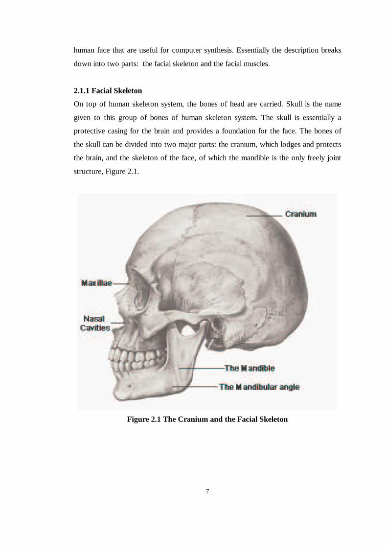
structure, Figure 2.1.
Figure 2.1 The Cranium and the Facial Skeleton
8
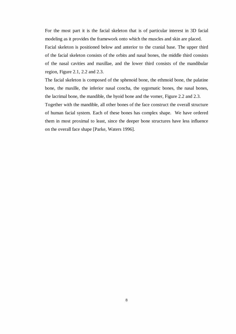
For the most part it is the facial skeleton that is of particular interest in 3D facial
modeling as it provides the framework onto which the muscles and skin are placed.
Facial skeleton is positioned below and anterior to the cranial base. The upper third
of the facial skeleton consists of the orbits and nasal bones, the middle third consists
of the nasal cavities and maxillae, and the lower third consists of the mandibular
region, Figure 2.1, 2.2 and 2.3.
The facial skeleton is composed of the sphenoid bone, the ethmoid bone, the palatine
bone, the maxille, the inferior nasal concha, the sygomatic bones, the nasal bones,
the lacrimal bone, the mandible, the hyoid bone and the vomer, Figure 2.2 and 2.3.
Together with the mandible, all other bones of the face construct the overall structure
of human facial system. Each of these bones has complex shape. We have ordered
them in most proximal to least, since the deeper bone structures have less influence
on the overall face shape [Parke, Waters 1996].
9
Figure 2.2 Facial Bones
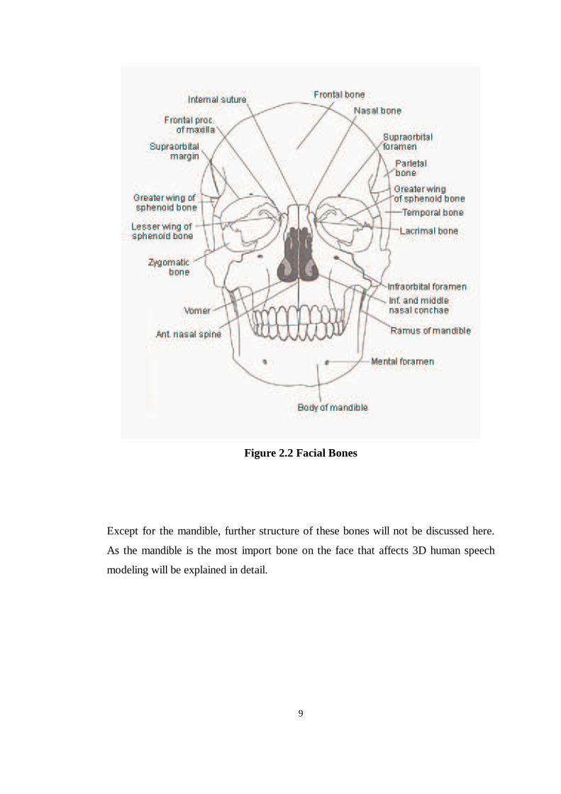
Except for the mandible, further structure of these bones will not be discussed here.
As the mandible is the most import bone on the face that affects 3D human speech
modeling will be explained in detail.
10
Figure 2.3 The Lateral view of the Skull
2.1.1.1 The Mandible
The mandible is the only movable joint on the human face. It is the major part of our
chin and every chin-movement including event of human facial system occurs within
the corporation of the mandible joint and its muscles.
11
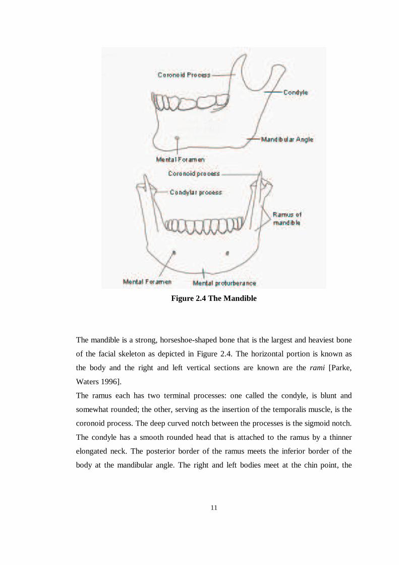
Figure 2.4 The Mandible
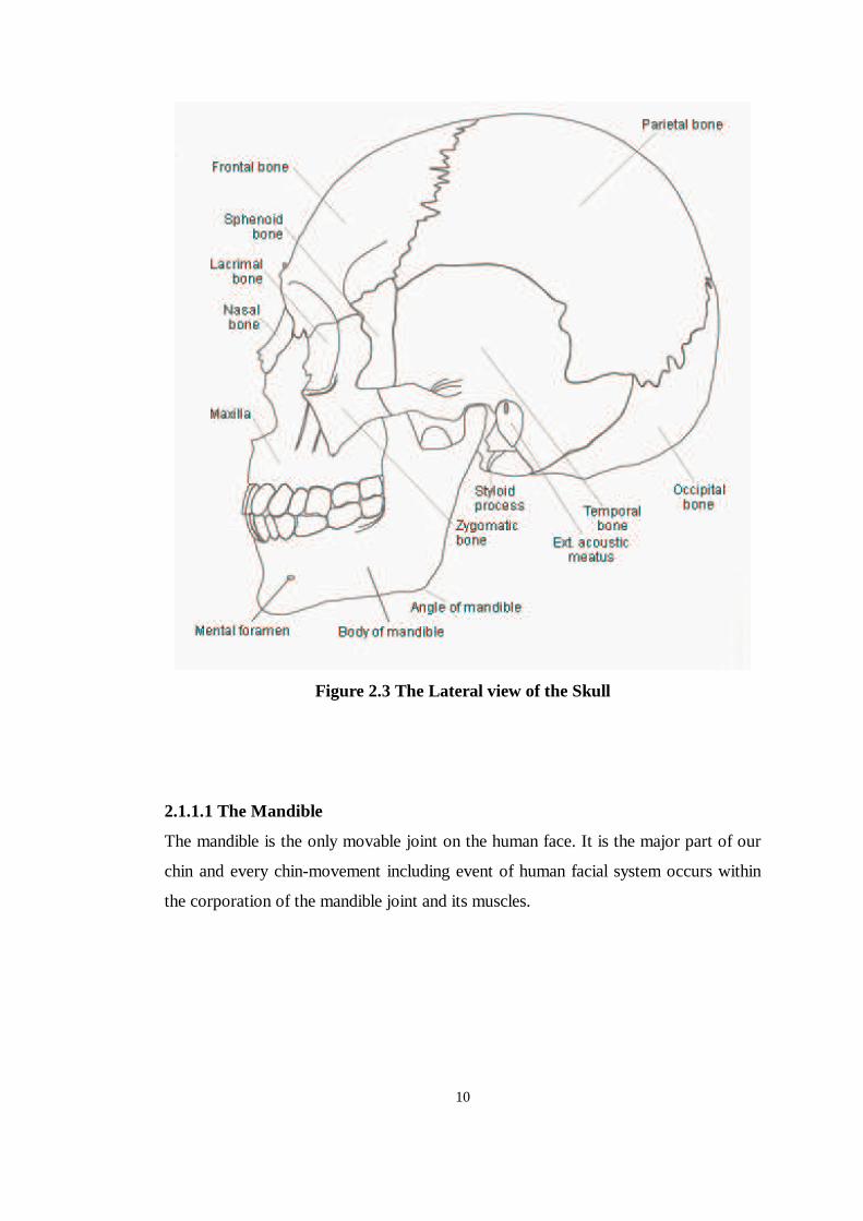
The mandible is a strong, horseshoe-shaped bone that is the largest and heaviest bone
of the facial skeleton as depicted in Figure 2.4. The horizontal portion is known as
the body and the right and left vertical sections are known are the rami [Parke,
Waters 1996].
The ramus each has two terminal processes: one called the condyle, is blunt and
somewhat rounded; the other, serving as the insertion of the temporalis muscle, is the
coronoid process. The deep curved notch between the processes is the sigmoid notch.
The condyle has a smooth rounded head that is attached to the ramus by a thinner
elongated neck. The posterior border of the ramus meets the inferior border of the
body at the mandibular angle. The right and left bodies meet at the chin point, the
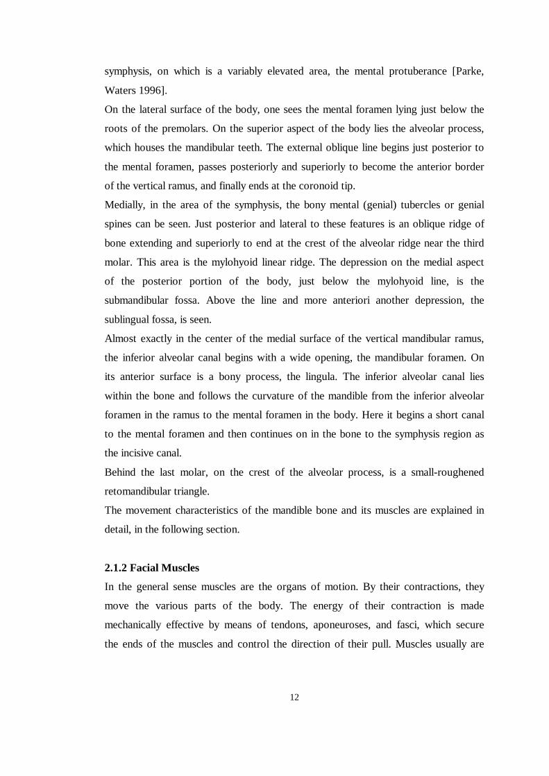
12
symphysis, on which is a variably elevated area, the mental protuberance [Parke,
Waters 1996].
On the lateral surface of the body, one sees the mental foramen lying just below the
roots of the premolars. On the superior aspect of the body lies the alveolar process,
which houses the mandibular teeth. The external oblique line begins just posterior to
the mental foramen, passes posteriorly and superiorly to become the anterior border
of the vertical ramus, and finally ends at the coronoid tip.
Medially, in the area of the symphysis, the bony mental (genial) tubercles or genial
spines can be seen. Just posterior and lateral to these features is an oblique ridge of
bone extending and superiorly to end at the crest of the alveolar ridge near the third
molar. This area is the mylohyoid linear ridge. The depression on the medial aspect
of the posterior portion of the body, just below the mylohyoid line, is the
submandibular fossa. Above the line and more anteriori another depression, the
sublingual fossa, is seen.
Almost exactly in the center of the medial surface of the vertical mandibular ramus,
the inferior alveolar canal begins with a wide opening, the mandibular foramen. On
its anterior surface is a bony process, the lingula. The inferior alveolar canal lies
within the bone and follows the curvature of the mandible from the inferior alveolar
foramen in the ramus to the mental foramen in the body. Here it begins a short canal
to the mental foramen and then continues on in the bone to the symphysis region as
the incisive canal.
Behind the last molar, on the crest of the alveolar process, is a small-roughened
retomandibular triangle.
The movement characteristics of the mandible bone and its muscles are explained in
detail, in the following section.
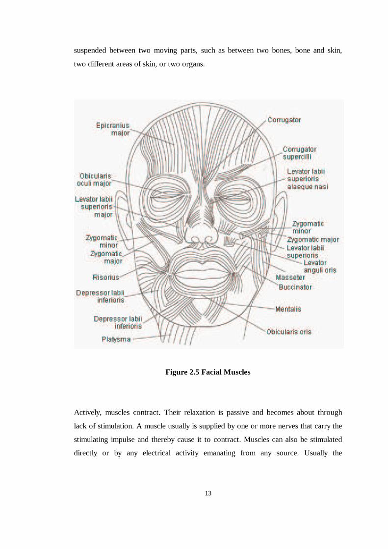
2.1.2 Facial Muscles
In the general sense muscles are the organs of motion. By their contractions, they
move the various parts of the body. The energy of their contraction is made
mechanically effective by means of tendons, aponeuroses, and fasci, which secure
the ends of the muscles and control the direction of their pull. Muscles usually are
13
suspended between two moving parts, such as between two bones, bone and skin,
two different areas of skin, or two organs.
Figure 2.5 Facial Muscles
Actively, muscles contract. Their relaxation is passive and becomes about through
lack of stimulation. A muscle usually is supplied by one or more nerves that carry the
stimulating impulse and thereby cause it to contract. Muscles can also be stimulated
directly or by any electrical activity emanating from any source. Usually the
14
stimulation for muscular contraction originates in the nerve supply to that muscle.
Lack of stimulation to the muscle results in relaxation.
When a muscle is suspended between two parts, one of which is fixed and the other
movable, the attachment of the muscle on the fixed part is known as the origin. The
attachment of the muscle to the movable part is referred as the insertion.
2.1.2.1 The Muscles of the Face
Facial muscles perform all of the functions of facial communication, such as moving
the cheeks, moving lips during mastication and speech, blinking eyelids and all of the
realizing all of the facial expressions.
The muscles of the face are superficial, and all attach to a layer of subcutaneous fat
and skin at their insertion. Some of the muscles attach to skin at both the origin and
the insertion such as the obicularis oris. When all the muscles are relaxed, the fatty
tissues fill the hollows and smooth the angular transitions so as to allow the general
shape of the skull to be seen.
The muscles of the face work synergistically and not independently. The group
function as a well-organized and coordinated team, each member having specified
functions, one of which is primary. These muscles interweave with one another. It is
difficult to separate the boundaries between the various muscles. The terminal ends
of these muscles are interlaced with each other.
In more general terms, the muscle of the face can be grouped according to the
orientation of the individual muscle fibers and can be divided into the upper and
lower face as depicted in Figure 2.5. Three types of muscle can be discerned as the
primary motion muscles: linear/parallel, which pull in angular direction, such as the
zygomatic major and the corrugator supercilii; elliptical/circular sphincter-type
muscles, which squeeze, such as the obicularis oris; sheet muscles, which behave as
a series of linear muscles spread over an area, such as the frontalis (see figure 2.5).
Since the focus of this thesis is mainly on visual speech modeling, the facial muscles
are studied roughly.
15
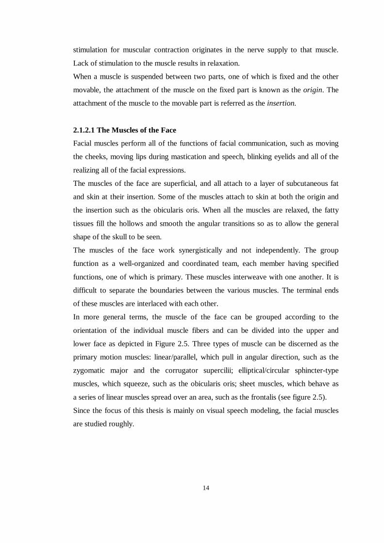
2.1.2.1.1 Circum-orbital Muscles of the Eye
Orbicularis Oculi. This muscle encircles the eye in concentric fibers that act as a
sphincter to close the eye.
Corrugator Supercilii. This small-paired pyramidal muscle is located at the medial
end of each brow. This muscle draws the brows medially and down, producing (with
the orbicularis oculi) vertical wrinkles on the forehead.
Levator Palpebrae Superioris. This muscle arises within the orbit above the optic
foramen and advances and spreads out to end in the upper eyelid. This muscle, when
is contracts, lifts the upper lid.
2.1.2.1.2 Muscles of the Nose
These muscles are quite rudimentary; however, they act to dilate and constrict the
nasal openings. They are illustrated in Figure 2.5 and Figure 2.6.
Procerus. The procerus muscle originates from the nasal bone and passes superiorly
to end in the brow and forehead. This muscle depresses the medial end of the
eyebrow, producing transverse wrinkles over the nasal bridge and root. The action of
this muscle aids in reducing the glare of bright sunlight.
Nasalis. The nasalis arises from the alveolar eminence over the lateral incisor and
swings around the nose to insert on the superior surface of the bridge, at the tip of the
nose and alar cartilages. The transverse part of this muscle compresses the nasal
aperture at the junction of the vestibule and nasal activity.
Depressor Septi. This muscle is attached to the maxilla above the central incisor and
ascends to the mobile part of the nasal septum. This muscle assists the alar part of the
nasalis in widening the nasal aperture.
Levator Labii Superioris Alaeque Nasi. This muscle raises the upper lip, deepening
the nasolabial furrows and slightly dilating the nostrils. This muscle is also counted
as one of the muscles of the mouth.
2.1.2.1.3 Muscles of the Mouth
The numerous muscles of the mouth are important in facial expression generation;
while one group of these muscles opens the lips, another group closes them. The
muscles closing the lips are the orbicularis oris and the incisive muscles. The
16
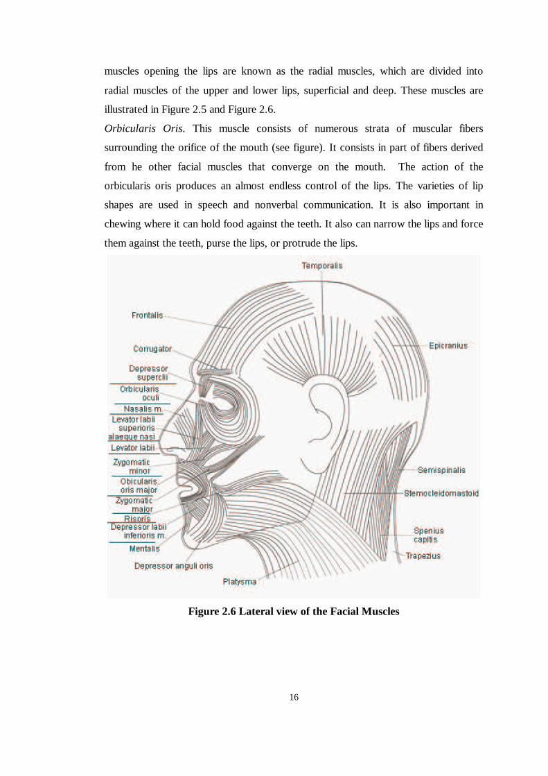
muscles opening the lips are known as the radial muscles, which are divided into
radial muscles of the upper and lower lips, superficial and deep. These muscles are
illustrated in Figure 2.5 and Figure 2.6.
Orbicularis Oris. This muscle consists of numerous strata of muscular fibers
surrounding the orifice of the mouth (see figure). It consists in part of fibers derived
from he other facial muscles that converge on the mouth. The action of the
orbicularis oris produces an almost endless control of the lips. The varieties of lip
shapes are used in speech and nonverbal communication. It is also important in
chewing where it can hold food against the teeth. It also can narrow the lips and force
them against the teeth, purse the lips, or protrude the lips.
Figure 2.6 Lateral view of the Facial Muscles
17
Buccinator. The buccinator muscle is thin, wide, and flat, forming the major portion
of the substance of the cheeks. The fibers run forward to blend with those of the
orbicularis oris. The buccinators compress the cheeks against the teeth, thereby
preventing the accumulation of food in the cheek.
Zygomaticus Major. This muscle arises from the malar surface of the zygomatic bone
and is inserted into the corner of the mouth. This muscle elevates the modiolus and
buccal angle, as in laughing.
Levator Anguli Oris. This muscle is slightly deeper than the overlaying zygomatic
muscles. This muscle raises the modiolus and buccal angle, displaying the teeth and
deepening the nasolabial furrows. This muscle is the only muscle in the deep layer of
muscles that open the lips. Its function is to elevate the angle of the mouth.
Depressor Anguli Oris and Depressor Labii Infeiroris. These muscles arise from the
mandible, and the fibers converge to the corners of the mouth. Both these muscles
depress the corner of the lips downward and laterally
Risorius. This muscle is one of those located at the corner of the mouth. This muscle
pulss the angle of the mouth laterally and is often referred to as “smiling muscle” .
Mentalis. This muscle originates in a circular area above the mental tuberosity. Its
action is to elevate the skin of the chin aiding its protrusion/eversion, as in drinking.
Depressor Anguli Oris. This muscle arises from the area near the insertion of the
platysma and inserts into the tendonous node at the angle of the mouth. It depresses
the modiolus and buccal angle laterally in opening the mouth and the expression of
sadness.
Depressor Labii Inferioris. This muscle originates near the origin of the triangular
muscle. It pulls the lower lip down and laterally in mastication.
2.1.2.1.4 The Muscles of Mandible and Mastication
The movement of the mandible is complex involving the coordinated action of the
muscles attached to it. Four basic movements of the mandible are:
��Protraction: pulling the mandible forward so that the head articulates
indirectly with the articular tubercle of the temporal bone.
��Retraction: pulling the mandible backward so that the head moves into the
mandibular fossa.
18
��Elevation: closing the mouth.
��Depression: opening the mouth.
The various muscles around the mandible are responsible for these four basic
movements of the mandible. These muscles are briefly:
Masseter. The action of this thick powerful muscle is to elevate the lower jaw.
Medial Pterygoid. This muscle acts as an elevator of the mandible so as to close the
mouth.
Temporalis. The fibers are somewhat longer and therefore the temporal muscle is
less powerful than the masseter, but it provides for rapid movement of the mandible.
Digastric. With the mandible fixed, the digastric raises the hyoid bone and, with it,
the larynx, which is an important action in swallowing.
Geniohyoid Muscle. This muscle principally assists the mylohyoid muscle in
elevating the tongue. It also elevates and fixes the hyoid bone depress the mandible.
Lateral Pterygoid. This muscle acts to open the jaw. It causes the mandible to shift to
the opposite side when it contracts without the aid of its contra-lateral mate.
Mylohyoid. The primary function of this muscle is to elevate the tongue. When the
fibers contract, the curvature is flatter; thus the floor of the mouth is elevated, and
with it, the tongue.
Platysma. The action of the platysma is to raise the skin of the neck, as if to relieve
the pressure of a tight collar. Also, this muscle draws the outer part of the lower lip
down and depresses the mandible. This action is seen in the expression of horror.
The muscles listed above are the main muscles responsible for facial expression
construction. But they are not the only ones. There are also several muscles of
tongue, scalp, ear and the neck. As the deeper analyses of these muscles are beyond
the scope of this thesis they are not examined here. But further information can be
found in [Parke, Waters 1996], [Fleming, Dobbs 1999], [Ferner, Staubesand 1985].
2.2 Structure And Dynamics Of Human Facial Expressions
Human face is a multi-message system. The face broadcasts messages about
emotions, mood, attitudes, character, intelligence, attractiveness, age, sex, race, and
probably other matters as well [Ekman, 1975]. When we speak of emotions, we are
19
referring to transitory feelings, such as fear, anger, surprise, etc. When these feelings
occur, the facial muscles contract and there are visible changes in the appearance of
the face. Wrinkles appear and disappear, the location and/or shape of the eyebrows,
eyes, eyelids, nostrils, lips, cheeks, and chin temporarily changes.
It is important to note that emotion messages are not dependent on whether a person
has a thin or fat face, a wrinkled or smooth face, a thin-lipped face, an old or young
face, a male or female face, a Black or Oriental face. As referred in the previous
section, a human face is formed of certain muscles that generate these facial
expressions. Generally human facial expressions are modeled according to these
facial muscles.
Human face experiences some number of facial expression or emotions. How many
of these specific emotions does the face show? The six emotions that are the subject
of this thesis, namely happiness, sadness, surprise, fear, anger and disgust, were
found by every investigator in the last fifty years who sought to determine the
vocabulary of emotion terms associated with facial expressions [Ekman, 1975].
There are probably other emotions conveyed by the face –shame and excitement, for
example; but these have not yet been firmly established.
2.2.1 Universal Facial Expressions
The first person, who tried to answer the question “are facial expressions of emotion
the same for people everywhere” , was Charles Darwin. He mentioned that facial
expressions of emotion are universal, not learned differently in each culture; that they
are biologically determined, the product of man’s evolution [Ekman, 1975]. Also
scientific investigations have conclusively settled this question, showing that the
facial appearances of at least some emotions, those covered in this thesis, are indeed
universal, although there are cultural differences in when these expressions are
shown.
Studies of Paul Ekman on facial muscle movements in 1970’s showed that when
people are alone Japanese and Americans had virtually identical facial expressions.
When in the presence of another person, however, where cultural rules about the
management of facial appearance would be applied, there was little correspondence
between Japanese and American facial expressions. Japanese masked their facial
20
expression of unpleasant feelings more than did Americans. This study was
particularly important in demonstrating what about facial expression is universal and
what differs for each culture. With the materials gathered in one of the cross-cultural
studies of facial expressions described earlier, Ekman and his colleagues managed to
form a Facial Atlas from which they could model six facial expressions, which are
happiness, sadness, anger, fear, surprise and disgust. This atlas is still used in many
facial expression simulations and several facial expression extraction applications.
As the examination of this Facial Atlas is beyond the scope of this thesis, we will
only examine the facial state of six basic expressions.
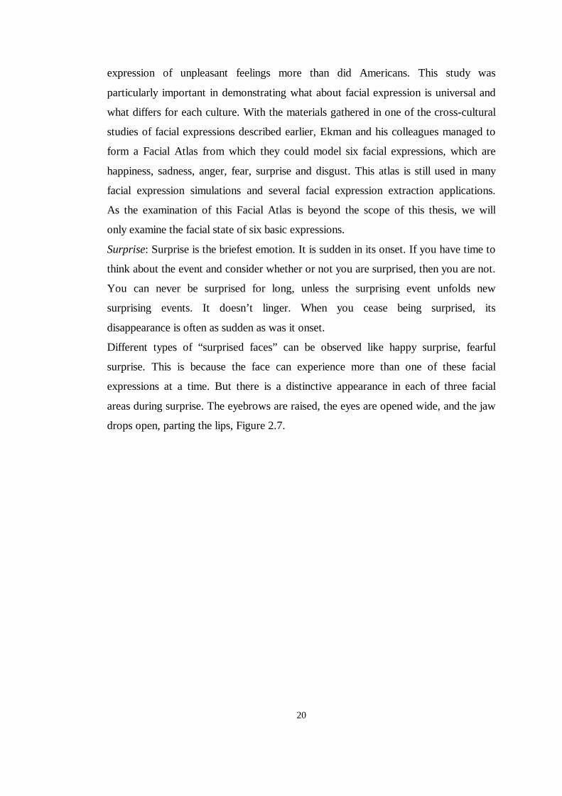
Surprise: Surprise is the briefest emotion. It is sudden in its onset. If you have time to
think about the event and consider whether or not you are surprised, then you are not.
You can never be surprised for long, unless the surprising event unfolds new
surprising events. It doesn’t linger. When you cease being surprised, its
disappearance is often as sudden as was it onset.
Different types of “surprised faces” can be observed like happy surprise, fearful
surprise. This is because the face can experience more than one of these facial
expressions at a time. But there is a distinctive appearance in each of three facial
areas during surprise. The eyebrows are raised, the eyes are opened wide, and the jaw
drops open, parting the lips, Figure 2.7.
21
Figure 2.7 Surprise and Surprise blended with happiness.
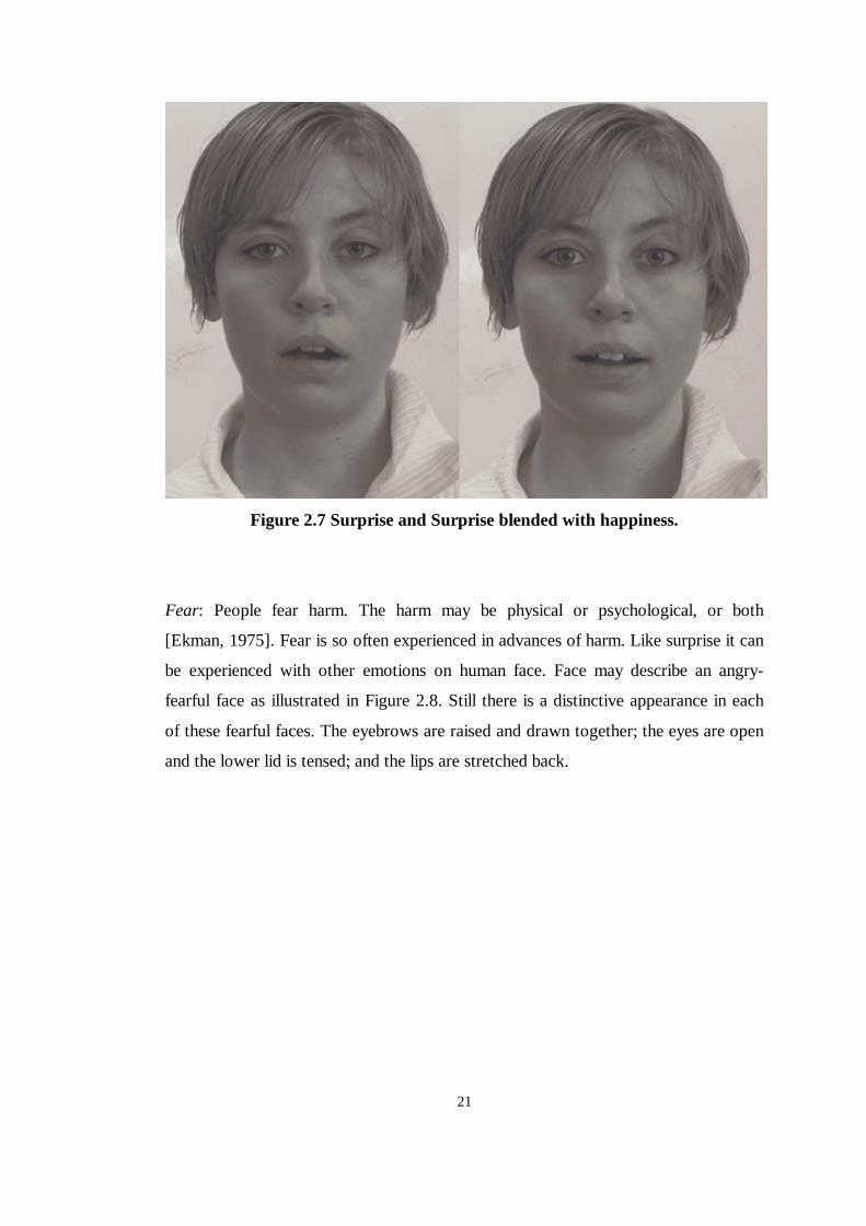
Fear: People fear harm. The harm may be physical or psychological, or both
[Ekman, 1975]. Fear is so often experienced in advances of harm. Like surprise it can
be experienced with other emotions on human face. Face may describe an angry-
fearful face as illustrated in Figure 2.8. Still there is a distinctive appearance in each
of these fearful faces. The eyebrows are raised and drawn together; the eyes are open
and the lower lid is tensed; and the lips are stretched back.
22
Figure 2.8 Fear blended with surprise.
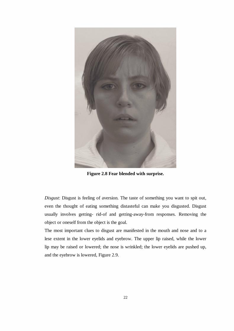
Disgust: Disgust is feeling of aversion. The taste of something you want to spit out,
even the thought of eating something distasteful can make you disgusted. Disgust
usually involves getting- rid-of and getting-away-from responses. Removing the
object or oneself from the object is the goal.
The most important clues to disgust are manifested in the mouth and nose and to a
lese extent in the lower eyelids and eyebrow. The upper lip raised, while the lower
lip may be raised or lowered; the nose is wrinkled; the lower eyelids are pushed up,
and the eyebrow is lowered, Figure 2.9.
23
Figure 2.9 Disgust.
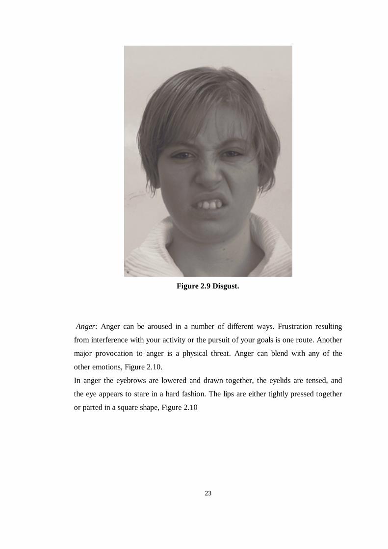
Anger: Anger can be aroused in a number of different ways. Frustration resulting
from interference with your activity or the pursuit of your goals is one route. Another
major provocation to anger is a physical threat. Anger can blend with any of the
other emotions, Figure 2.10.
In anger the eyebrows are lowered and drawn together, the eyelids are tensed, and
the eye appears to stare in a hard fashion. The lips are either tightly pressed together
or parted in a square shape, Figure 2.10
24
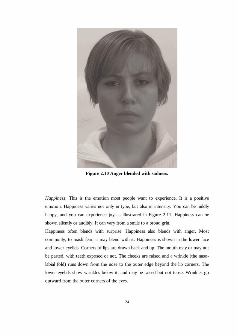
Figure 2.10 Anger blended with sadness.
Happiness: This is the emotion most people want to experience. It is a positive
emotion. Happiness varies not only in type, but also in intensity. You can be mildly
happy, and you can experience joy as illustrated in Figure 2.11. Happiness can be
shown silently or audibly. It can vary from a smile to a broad grin.
Happiness often blends with surprise. Happiness also blends with anger. Most
commonly, to mask fear, it may blend with it. Happiness is shown in the lower face
and lower eyelids. Corners of lips are drawn back and up. The mouth may or may not
be parted, with teeth exposed or not. The cheeks are raised and a wrinkle (the naso-
labial fold) runs down from the nose to the outer edge beyond the lip corners. The
lower eyelids show wrinkles below it, and may be raised but not tense. Wrinkles go
outward from the outer corners of the eyes.
25
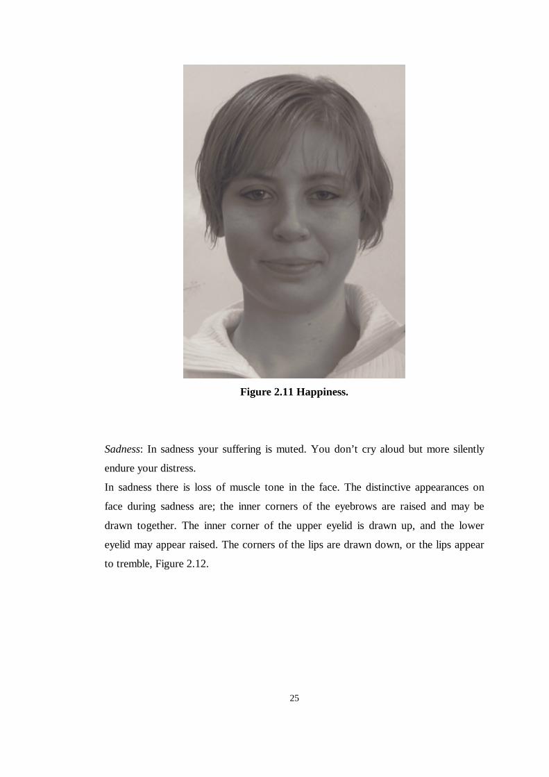
Figure 2.11 Happiness.
Sadness: In sadness your suffering is muted. You don’t cry aloud but more silently
endure your distress.
In sadness there is loss of muscle tone in the face. The distinctive appearances on
face during sadness are; the inner corners of the eyebrows are raised and may be
drawn together. The inner corner of the upper eyelid is drawn up, and the lower
eyelid may appear raised. The corners of the lips are drawn down, or the lips appear
to tremble, Figure 2.12.
26
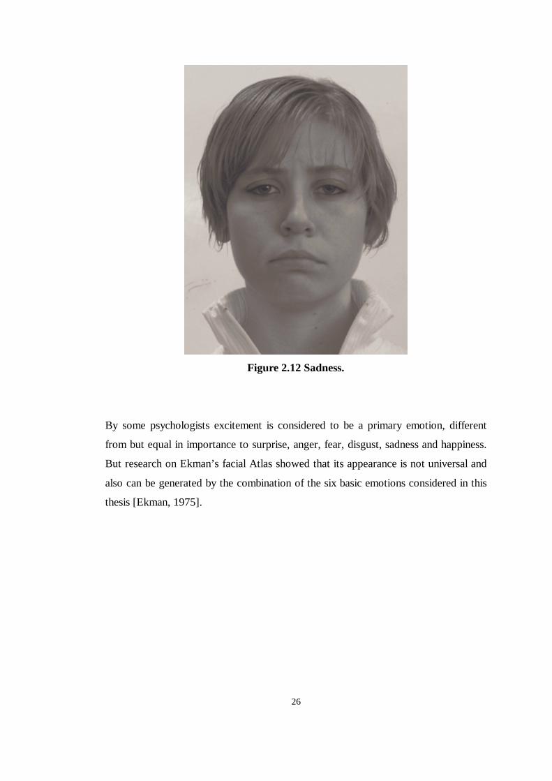
Figure 2.12 Sadness.
By some psychologists excitement is considered to be a primary emotion, different
from but equal in importance to surprise, anger, fear, disgust, sadness and happiness.
But research on Ekman’s facial Atlas showed that its appearance is not universal and
also can be generated by the combination of the six basic emotions considered in this
thesis [Ekman, 1975].
27
CHAPTER 3
TURKISH SPEECH AND LIP MOTION
Turkish is a very ancient language, with a flawless phonetic, morphological and
syntactic structure, and at the same time possesses a wealth of vocabulary. The
fundamental features which distinguish the Ural-Altaic languages from the Indo-
European are as follows:
��Vowel harmony, a feature of all Ural-Altaic tongues.
��The absence of gender.
��Agglutination
��Adjectives precede nouns.
��Verbs come at the end of the sentence.
In this chapter we will briefly explain vocal and structural properties of Turkish
language. As these features are beyond the scope of this thesis, we will avoid getting
into detail. In addition we will explain lip motion in Turkish Language.
3.1 Vocal and Structural Properties of Turkish Language
Turkish is characterized by certain morphophonemic, morpho-tactic, and syntactic
features: vowel harmony, agglutination of all-suffixing morphemes, free order of
constituents, and head-final structure of phrases. Turkish is an agglutinative language
with word structures formed by productive affixations of derivational and
inflectional suffixes to root words. [Bilkent CTLP]. There is extensive usage of
28
suffixes in Turkish Language, which causes morphological parsing of words to be
rather complicated, and results in ambiguous lexical interpretations in many cases.
Turkish can be characterized as being a subject-object-verb language. However,
other orders for constituents are also common. In Turkish it is not the position, but
the case of a noun phrase that determines its grammatical function in the sentence.
Consequently typical order of the constituents may change rather freely without
affecting the grammaticality of a sentence. Due to various syntactic and pragmatic
constraints, sentences with the non-typical orders are not stylistic variants of the
typical versions, which can be used interchangeably in any context.
The extensive usage of suffixes makes Turkish a difficult language for lip
motion/speech synchronization. Compared to languages like Chinese, words lengths
are longer in Turkish and phoneme-by-phoneme synchronization is required instead
of word-by-word synchronization.
The duration of vowels is a characteristic property of that language. There is average
duration of words for certain speaking rate. In vocal interpretation, we see that there
is no pause between words of Turkish Language [Salor 1999]. This means that a
foreigner, who cannot speak Turkish, won’t be able to extract words from a Turkish
speech sequence that she hears.
There are definite properties of Turkish language like duration, tone, intonation,
accent etc. [Ergenç 1995]. As further analysis of Turkish language is beyond the
scope of this thesis we will limit our explanations on vocal and structural properties
of Turkish language to this point.
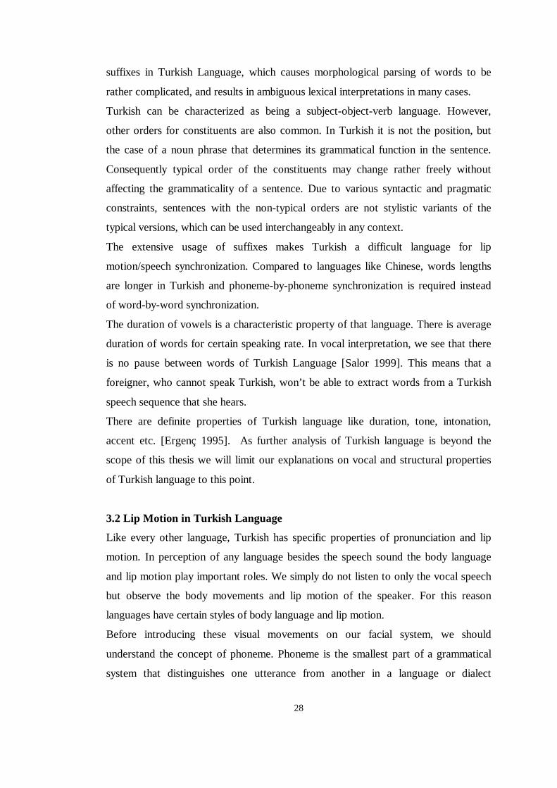
3.2 L ip Motion in Turkish Language
Like every other language, Turkish has specific properties of pronunciation and lip
motion. In perception of any language besides the speech sound the body language
and lip motion play important roles. We simply do not listen to only the vocal speech
but observe the body movements and lip motion of the speaker. For this reason
languages have certain styles of body language and lip motion.
Before introducing these visual movements on our facial system, we should
understand the concept of phoneme. Phoneme is the smallest part of a grammatical
system that distinguishes one utterance from another in a language or dialect
29
[Fleming, Dobbs 1999]. Phoneme represents both vocal part and visual part of the
speaking action, that’s why we will further examine it in two concepts as vocal
phoneme and visual phoneme.
Modern standard Turkish is a phoneme-based language like Finnish or Japanese,
which means phonemes, are represented by letters in the written language [Salor
1999]. It is also true to say that there is nearly one-to-one mapping between written
text and its pronunciation. However, some vowels and consonants have variants
depending on the place they are produced in the vocal tract [Salor 1999].
The vocal phonemes are the smallest part of our vocal speech sequence. In other
words a phoneme is one distinguishable sound in a speech sequence. In English
phonetic speech, combining phonemes, rather than the actual letters in the word,
creates words [Fleming, Dobbs 1999]. In Turkish the case is somewhat different. In
Turkish we have “syllables” . Syllable is one part of a word, which can be
pronounced with a single effort of our vocal system. In Turkish speech syllables
contain only one single vowel. Actually this property is the most distinctive property
of Turkish syllables. Turkish syllables may contain one or more than one number of
phonemes.
The visual phoneme is the mouth position that represents the sound we hear in
speech [Fleming, Dobbs 1999]. Under each visual phoneme one will find the audible
phonemes that are associated to that specific mouth position. A visual phoneme
includes the position of the mouth, the lips and the tongue. In next subsection
Turkish phonemes are explained in detail.
3.2.1 Turkish Visual Phonemes
In this subsection Turkish visual phonemes will be examined in letter basis. Each
letter will be matched to visual phoneme, which will later be used as models in our
morphing simulation.
Visual phonemes are characterized with articulators. Articulators are the places
where various obstructions take place in human mouth [Fleming, Dobbs 1999]. Some
important ones of these places are:
Lips (labial)
Teeth (dental)
30
Hard Palate (palatal)
Soft palate (velar)
Back of throat (uvula/glottis)
Turkish alphabet has 29 letters. These 29 letters in the Turkish alphabet are
represented by 45 phonetic symbols [Salor 1999]. Below we have made a list of
visual phonemes mapping to every letter in Turkish language. This list is constructed
according to our analysis in human facial system and daily Turkish speech. The
information given for each visual phoneme only includes positions for mouth, lips,
teeth and tongue. According to our simulation’s visual needs, further information on
human vocal system, like throat etc, is ignored. Some examples of these visual
phonemes are illustrated in Figures 3.1, 3.2, 3.3, 3.4 and 3.5.
“A” : The mouth is open and un-rounded. The tongue is passive.
“B” : The mouth is closed. Lips touch each other.
“C” : The lower jaw is closed. Lips are open and slightly curved forward. The
tongue is raised, but it does not touch the palate.

31
Figure 3.1 Visual Phoneme “ c”
“Ç” : Same as “C” the lower jaw is closed and the lips are open and slightly curved
forward. But “ç” is a plosive sound so the tongue touches the palate.
“D” : The tongue touches the palate. Lower jaw is parted from the upper jaw with a
little opening from which the tip of the tongue can be seen.
“E” : The mouth is open and un-rounded. The tongue is slightly forward and down.
32
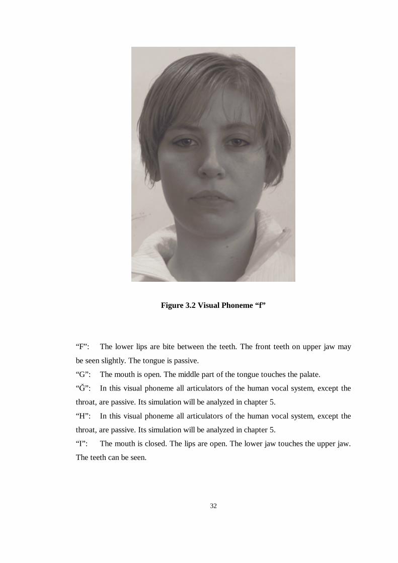
Figure 3.2 Visual Phoneme “ f”
“F” : The lower lips are bite between the teeth. The front teeth on upper jaw may
be seen slightly. The tongue is passive.
“G”: The mouth is open. The middle part of the tongue touches the palate.
“�” : In this visual phoneme all articulators of the human vocal system, except the
throat, are passive. Its simulation will be analyzed in chapter 5.
“H” : In this visual phoneme all articulators of the human vocal system, except the
throat, are passive. Its simulation will be analyzed in chapter 5.
“I” : The mouth is closed. The lips are open. The lower jaw touches the upper jaw.
The teeth can be seen.
33
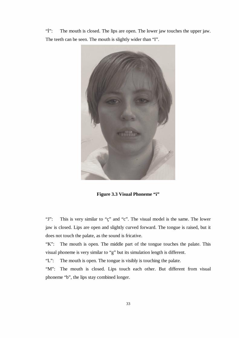
“�” : The mouth is closed. The lips are open. The lower jaw touches the upper jaw.
The teeth can be seen. The mouth is slightly wider than “I” .
Figure 3.3 Visual Phoneme “ i”
“J” : This is very similar to “ç” and “c” . The visual model is the same. The lower
jaw is closed. Lips are open and slightly curved forward. The tongue is raised, but it
does not touch the palate, as the sound is fricative.
“K” : The mouth is open. The middle part of the tongue touches the palate. This
visual phoneme is very similar to “g” but its simulation length is different.
“L” : The mouth is open. The tongue is visibly is touching the palate.
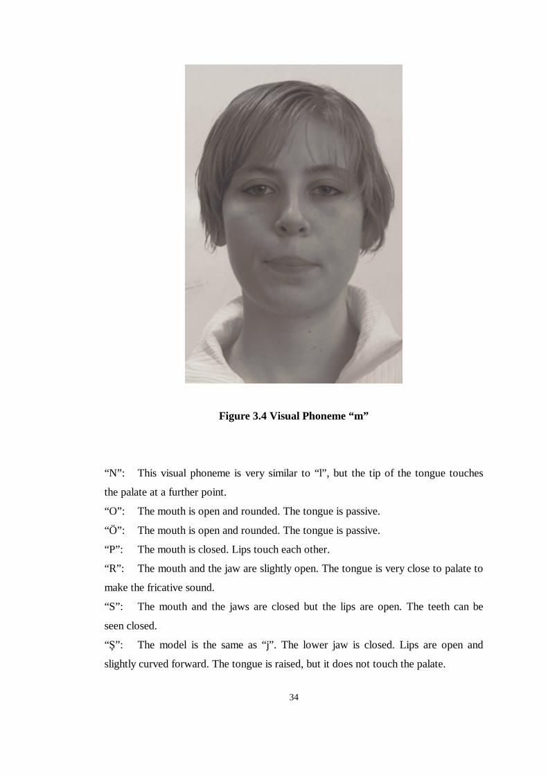
“M”: The mouth is closed. Lips touch each other. But different from visual
phoneme “b” , the lips stay combined longer.
34
Figure 3.4 Visual Phoneme “ m”
“N” : This visual phoneme is very similar to “ l” , but the tip of the tongue touches
the palate at a further point.
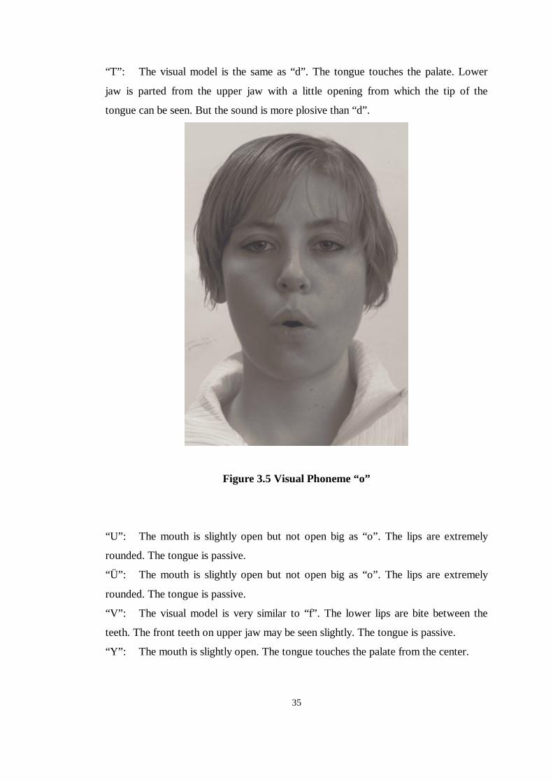
“O”: The mouth is open and rounded. The tongue is passive.
“Ö”: The mouth is open and rounded. The tongue is passive.
“P” : The mouth is closed. Lips touch each other.
“R” : The mouth and the jaw are slightly open. The tongue is very close to palate to
make the fricative sound.
“S” : The mouth and the jaws are closed but the lips are open. The teeth can be
seen closed.
“�” : The model is the same as “j” . The lower jaw is closed. Lips are open and
slightly curved forward. The tongue is raised, but it does not touch the palate.
35
“T” : The visual model is the same as “d” . The tongue touches the palate. Lower
jaw is parted from the upper jaw with a little opening from which the tip of the
tongue can be seen. But the sound is more plosive than “d” .
Figure 3.5 Visual Phoneme “ o”
“U” : The mouth is slightly open but not open big as “o” . The lips are extremely
rounded. The tongue is passive.
“Ü” : The mouth is slightly open but not open big as “o” . The lips are extremely
rounded. The tongue is passive.
“V” : The visual model is very similar to “f” . The lower lips are bite between the
teeth. The front teeth on upper jaw may be seen slightly. The tongue is passive.
“Y” : The mouth is slightly open. The tongue touches the palate from the center.
36
“Z” : The visual model is very similar to “s” . The mouth and the jaws are closed
but the lips are open. The teeth can be seen closed. But the tongue is not passive.
Instead it is close to the teeth to make the fricative sound.
37
CHAPTER 4
3D VIRTUAL SYSTEMS, 3D FACIAL MODELS AND 3D
FACIAL EXPRESSIONS
4.1 3D Virtual Systems
3D virtual system refers to any system that represents 3D virtual geometries by
means of any display device. The system can be a personal computer with a 3D
rendering software used to render a 3D geometry object or a 3D projection device
used to render a 3D scene. The basic features of these systems are; 3D objects and
rendering. 3D object is a geometry that is formed of 3D points. 3D point is a three
dimensional geometry object including three orthogonal space dimension values.
Consequently a 3D object is simply an array of 3D points.
Rendering is a jargon word that has come to mean “the collection of operations
necessary to project a view of an object or a scene onto a view surface” [Watt 1993].
For example; the object is lit and its interaction with a light source is calculated; in
other words the object is rendered. In personal computers rendering is achieved via
both software and hardware operations.
Briefly every 3D virtual system is a means of rendering device to visualize a 3D
object via a display tool. A scene composed of 3D virtual objects and their behaviors
over time or any kind of interrupt is called a 3D scene or a 3D virtual world, Figure
4.1.
38
Figure 4.1 3D virtual Scene including 3D objects
4.2 3D Facial Models
The face has a very complex, flexible, three-dimensional surface. It has color and
texture variation and usually contains creases and wrinkles. As presented in Chapter
2, the detailed anatomy of the head and face is a complex dynamic assembly of
bones, cartilage, muscles, nerves, blood vessels, glands, fatty tissue, connective
tissue and skin. Until now, no facial animation model, which represents and simulate
this complete, detailed anatomy have been reported. For some applications, such as
medical visualization and surgical planning, complete detailed models are the
ultimate goal. Fortunately, a number of useful applications, such as character
animation, can be accomplished with facial models that approximate only some
aspects of the complete facial anatomy.
The goal of the various animation techniques is to control the modeled faces, over
time, such that the rendered facial surfaces have the desired shapes, colors, and the
textures in each frame of the animated sequence. Different representations of 3D
facial geometry require different kinds of techniques to animate the facial geometry.
These different kinds of representation models are discussed below.
4.2.1 Volume Representations
One approach to representing faces is to use one of the many volume representation
techniques. These include constructive solid geometry, volume element (voxel)
arrays.
39
Constructive solid geometry is used successfully as the basis for a number of
computer-aided mechanical design systems. For these systems the objects of interest
are represented using boolean set constructions of relatively simple regular
mathematical shapes, such as planes, cylinders or spheres. Unfortunately, realistic
faces are not easily represented in this way. Therefore, this method has not been a
popular geometric basis for faces. However, one can imagine a particular style of
three-dimensional cartoon faces might be constructed using this technique.
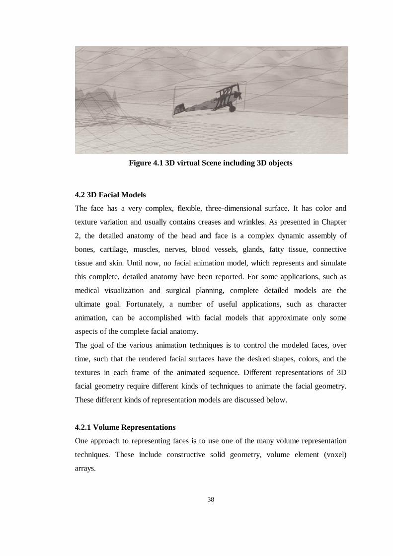
Volume element, or voxel, representation is preferred way of describing anatomical
structure in medical imaging. These representations may be assembled from two-
dimensional data slices of three-dimensional structures. These two-dimensional
slices may, for example, be obtained using multiple calibrated views [Mülayim
2002]. Detailed voxel representations typically require huge amounts of memory,
Figure 4.2.
Figure 4.2 3D Voxel Representation
40
Direct voxel models are not currently used for facial animation. However voxel
models can be used to extract the 3D geometry of the facial structure. Animation
may then be done using the extracted surface models.
The extracted surfaces usually are constructed to follow specific structure boundaries
in voxel data. The structure boundaries are associated with transitions between
regions of specific constant densities within the voxel data.
4.2.2 Surface Representations
Possible surface description techniques include implicit surfaces, parametric surfaces
and polygonal surfaces [Parke, Waters 1996]. Parametric surfaces include bivariate
Bëzier, Beta-spline, B-spline and NURB surfaces [Parke, Waters 1996]. Polygonal
surfaces include regular polygonal meshes and arbitrary polygon networks.
Implicit Surfaces: One approach is to find an analytical surface collection of surfaces
to approximate the surface of the face. An implicit surface is defined by a function
F(x,y,z,) that assigns a scalar value to each point in x, y, z space. The implicit surface
defined by such a function set is the set of points such that:
( ) 0,, =zyxF (4.1)
For example, a sphere of unit radius centered at ( )2,1,0 − would be described by the
implicit function
1)3()1(),,( 222 −++−+= zyxzyxf (4.2)
Any polynomial function ),,( zyxf implicitly describes an algebraic surface.
Although implicit surfaces are commonly expressed analytically, it is pointed out
that the defining functions could be any procedure that computes a scalar value for
every point in space. Models constructed with such procedures are called procedural
implicit models [Ricci 1973].
The blending and constraint properties of implicit surfaces allow creation of models
that would be difficult to build with other techniques [Parke, Waters 1996].
41
Parametric Surfaces: Bivariate parametric functions are used widely to define three-
dimensional surfaces. These surfaces are generated by functions that are typically
based on quadric or cubic polynomials.
Usually these surfaces are defined in terms of control values and basis functions.
Examples of these include B-splines, Beta-splines, Bèzier patches and nonuniform
rational B-spline surfaces, which are commonly called NURBS. These surface are
generally expressed in the form
��=j
mjkijii
vBuBVvuS )()(),( ,,, (4.3)
where ),( vuS is the parametric surface, jiV , are the control values and )(, uB ki ,
)(, vB mj are the basis functions of polynomial orders m and k. In the matrix
representation the formulation is seen as.
[ ] [ ] [ ] [ ] [ ] Tm
Tjmvjiikuk vBVBuvuS ×××××= 11),( (4.4)
where [u] = [1 u u2 ··· uk-1] and [v] = [1 v v2 ··· vm-1]
and i and j are the number of control points.
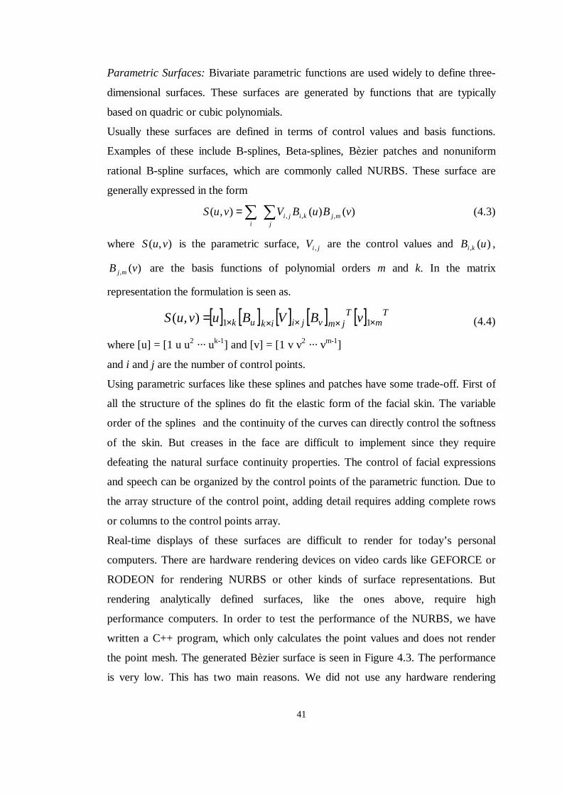
Using parametric surfaces like these splines and patches have some trade-off. First of
all the structure of the splines do fit the elastic form of the facial skin. The variable
order of the splines and the continuity of the curves can directly control the softness
of the skin. But creases in the face are difficult to implement since they require
defeating the natural surface continuity properties. The control of facial expressions
and speech can be organized by the control points of the parametric function. Due to
the array structure of the control point, adding detail requires adding complete rows
or columns to the control points array.
Real-time displays of these surfaces are difficult to render for today’s personal
computers. There are hardware rendering devices on video cards like GEFORCE or
RODEON for rendering NURBS or other kinds of surface representations. But
rendering analytically defined surfaces, like the ones above, require high
performance computers. In order to test the performance of the NURBS, we have
written a C++ program, which only calculates the point values and does not render
the point mesh. The generated Bèzier surface is seen in Figure 4.3. The performance
is very low. This has two main reasons. We did not use any hardware rendering
42
capabilities of the video card device. But one should remember that the NURB
surface support of these video cards is still very inadequate. The second reason is that
calculation of the parametric function is a huge amount of processing burden.
Figure 4.3 Beizer Control Points and Bezier Surface Patch: The surface patch
seen above has 5x5, totally 25 control points. According to Bezier curve fitting
formulas, the curves that form the surface patch seen above are of degree 5. The total
time elapsed for calculation of this 5x5 Bezier surface patch took 812 milliseconds.
This value corresponds to 1.23 frames/sec. As the degree of the curves and numbers
control points increase, the elapsed time increases rapidly. We have tested the
software on a P4, 2.4Ghz, 512 MB Intel machine.
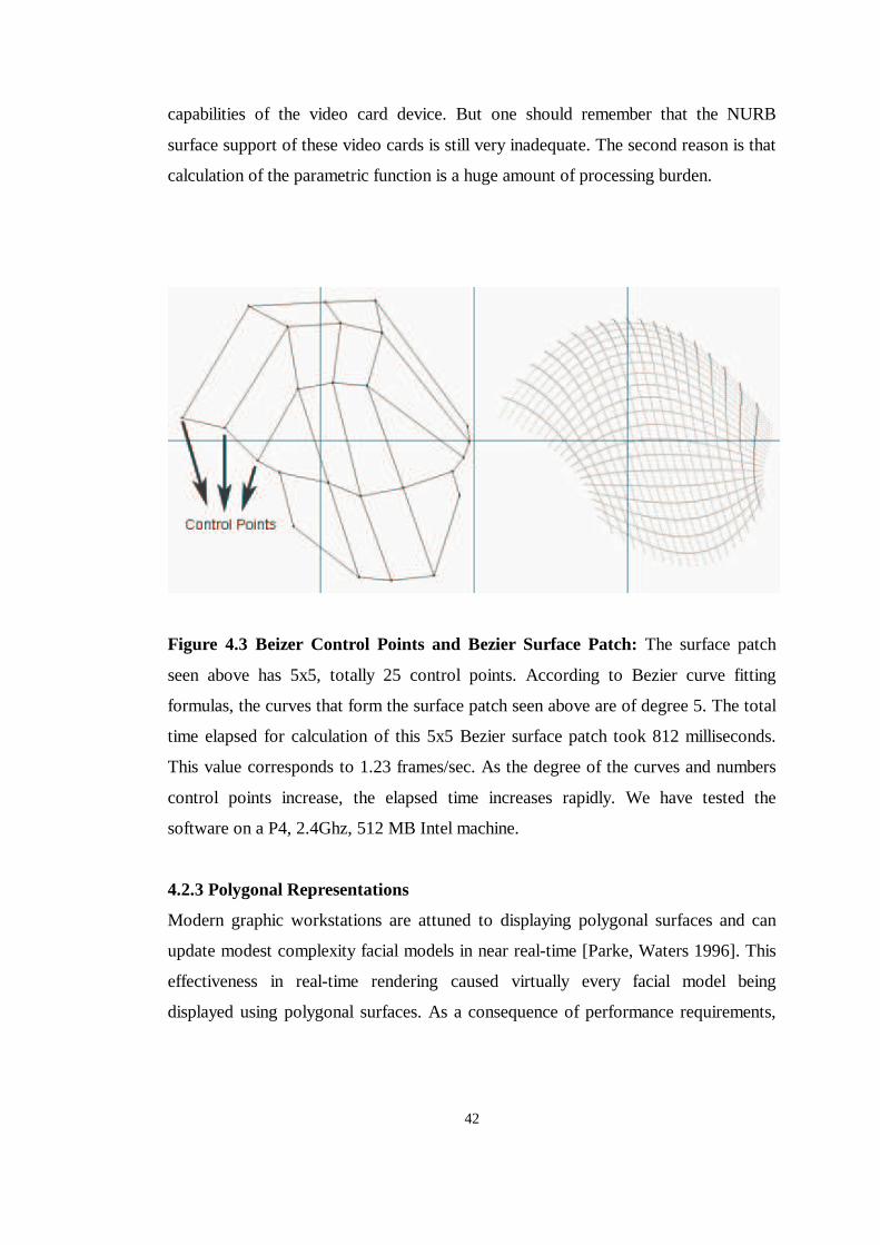
4.2.3 Polygonal Representations
Modern graphic workstations are attuned to displaying polygonal surfaces and can
update modest complexity facial models in near real-time [Parke, Waters 1996]. This
effectiveness in real-time rendering caused virtually every facial model being
displayed using polygonal surfaces. As a consequence of performance requirements,
43
even the non-polygonal surface techniques described above are approximated with
polygonal surfaces for display.
Figure 4.4 A Polygonal Mesh
Polygonal display is mainly based on forming polygons using the vertices of the 3D
model. Vertices are the 3D point coordinates that build the 3D model. But a vertex
does not only include the 3D point coordinate information, it also may include 3D
normal coordinate information and it may or may not include the texture and color
coordinates.
44
Point coordinates are simply the x, y, z values of the points that build a model. These
are the space coordinates and they simply specify the position of the model in virtual
space.
A polygonal model is formed of simply polygons, Figure 4.4. Some of these 3D
points come together to form the polygons. These 3D point groups are distinct for
each model. So besides the vertex information, which carries the space, normal,
texture and color coordinate data, the information of “which vertices form groups to
make the polygons” is also carried in the 3D object file.
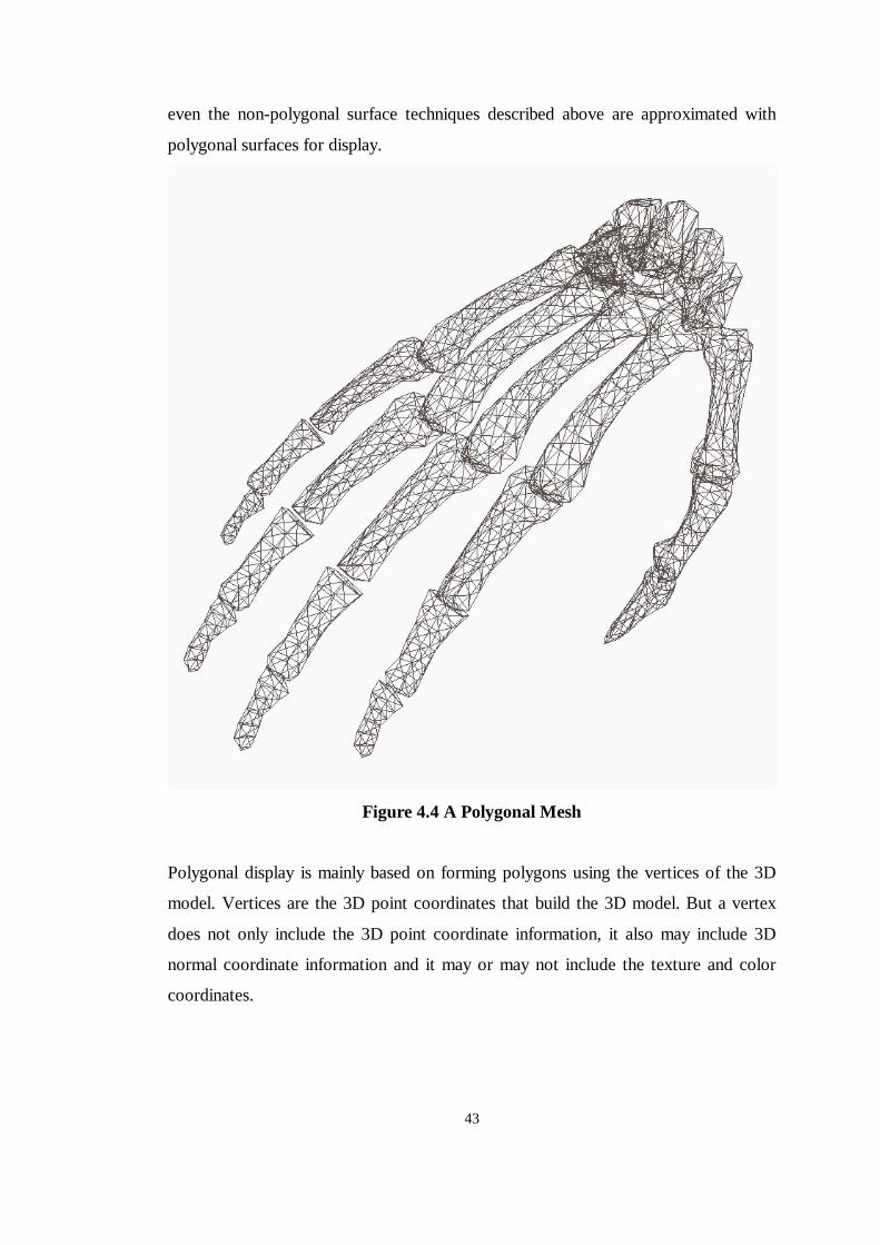
Figure 4.5 Cube rendered with color properties
After the polygonal meshes are formed every polygon specifies a surface. Each of
these surfaces has a normal vector. This normal vector is very important in light and
other virtual world calculations. The normal values are calculated according to the
polygonal mesh structure of the 3D object and stored as normal coordinates.
45
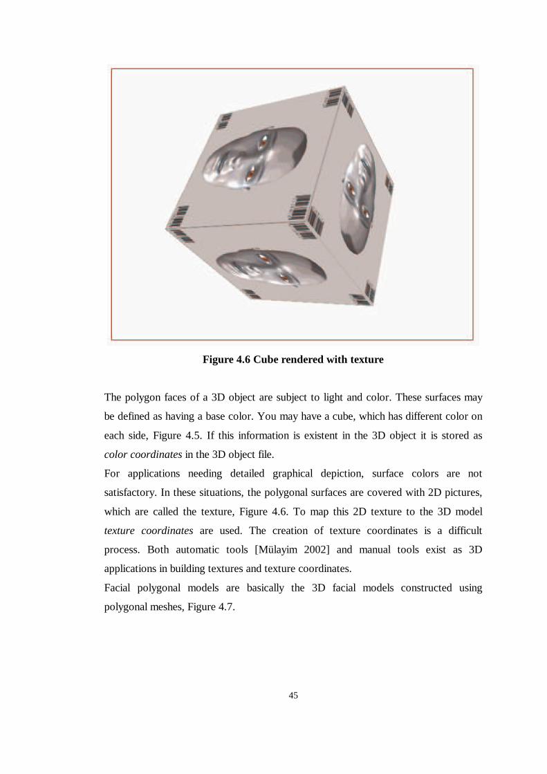
Figure 4.6 Cube rendered with texture
The polygon faces of a 3D object are subject to light and color. These surfaces may
be defined as having a base color. You may have a cube, which has different color on
each side, Figure 4.5. If this information is existent in the 3D object it is stored as
color coordinates in the 3D object file.
For applications needing detailed graphical depiction, surface colors are not
satisfactory. In these situations, the polygonal surfaces are covered with 2D pictures,
which are called the texture, Figure 4.6. To map this 2D texture to the 3D model
texture coordinates are used. The creation of texture coordinates is a difficult
process. Both automatic tools [Mülayim 2002] and manual tools exist as 3D
applications in building textures and texture coordinates.
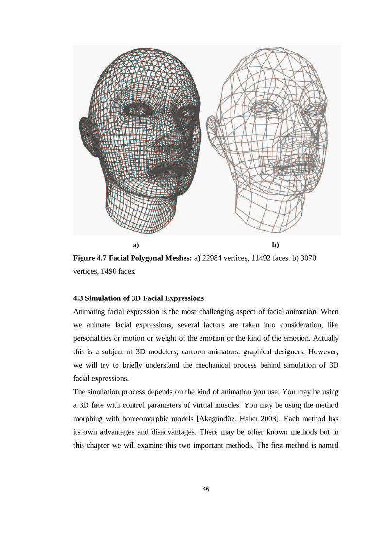
Facial polygonal models are basically the 3D facial models constructed using
polygonal meshes, Figure 4.7.
46
a) b)
Figure 4.7 Facial Polygonal Meshes: a) 22984 vertices, 11492 faces. b) 3070
vertices, 1490 faces.
4.3 Simulation of 3D Facial Expressions
Animating facial expression is the most challenging aspect of facial animation. When
we animate facial expressions, several factors are taken into consideration, like
personalities or motion or weight of the emotion or the kind of the emotion. Actually
this is a subject of 3D modelers, cartoon animators, graphical designers. However,
we will try to briefly understand the mechanical process behind simulation of 3D
facial expressions.
The simulation process depends on the kind of animation you use. You may be using
a 3D face with control parameters of virtual muscles. You may be using the method
morphing with homeomorphic models [Akagündüz, Halıcı 2003]. Each method has
its own advantages and disadvantages. There may be other known methods but in
this chapter we will examine this two important methods. The first method is named
47
control parameterization and it is the most commonly used method. The other
method is morphing, which is the one we have used in this study.
Control parameterization: In this method the development of facial animation may
be viewed as two independent activities: the development of control
parameterizations and associated user interfaces, and the development of techniques
to implement facial animation based on these parameters [Parke, Waters 1996].
Basically in this method the movement on face is modeled in relation to some
criteria. These criteria may be the movement of facial muscles, or the elastic
movement of the facial skin. The main idea can be described as understanding the
motion capabilities of the face and by extracting every independent motion on the
face, implementing these parameters on a virtual face model.
As this method depends on the control parameters, only one facial model is kept at
memory during software simulation. For this reason we may say that the method is a
memory-friendly implementation. On this model the desired animation is achieved by
controlling the parameters. But when it comes to the processor performance, it is not
the same. Every frame requires parameter calculation, which requires extra CPU
usage. This method is widely used for realistic and artistic animations. Today’s
Hollywood movies use this method to animate their computer-generated characters.
Needless to say that real-time rendering is avoided in this method. There are real-
time rendered examples of this implementation method, but the reality and artistic
view of the animation is highly reduced in those examples.
Morphing: Animation of three-dimensional shapes involves the change of vertex
attributes over time. Morphing represents such changes over time as the interpolation
of two given shapes. We can extend this concept to more than two base shape and
use morphing to produce blends of several objects. The interpolation function can be
summarized as,
Let I be a geometry array formed of the vertices I i, the orthogonal coordinates being
represented as I ix, I iy and I iz.
Let T be the target object, I the initial object, the O the output object.
Let αααα be the morphing weight, where 0.10 ≤≤ α
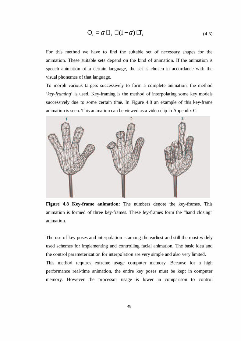
48
iii Τ⋅−+Ι⋅=Ο )1( αα (4.5)
For this method we have to find the suitable set of necessary shapes for the
animation. These suitable sets depend on the kind of animation. If the animation is
speech animation of a certain language, the set is chosen in accordance with the
visual phonemes of that language.
To morph various targets successively to form a complete animation, the method
‘key-framing’ is used. Key-framing is the method of interpolating some key models
successively due to some certain time. In Figure 4.8 an example of this key-frame
animation is seen. This animation can be viewed as a video clip in Appendix C.
Figure 4.8 Key-frame animation: The numbers denote the key-frames. This
animation is formed of three key-frames. These fey-frames form the “hand closing”
animation.
The use of key poses and interpolation is among the earliest and still the most widely
used schemes for implementing and controlling facial animation. The basic idea and
the control parameterization for interpolation are very simple and also very limited.
This method requires extreme usage computer memory. Because for a high
performance real-time animation, the entire key poses must be kept in computer
memory. However the processor usage is lower in comparison to control
49
parameterization. Except for the rendering calculations, which are mainly calculated
in video card processors, the only calculation is the simple interpolation function.
Further examination of this method is detailed in Chapter 5, as this method is the
main animation method that we have used in this thesis.
50
CHAPTER 5
SIMULATION AND SYNCHRONIZATION OF TURKISH LIP
MOTION IN A 3D ENVIRONMENT WITH A TURKISH SPEECH
ENGINE
As it was mentioned in the previous chapter the main method of animation in this
thesis is morphing. 3D morphing used with key-frame poses is a very efficient
algorithm for facial animation. The theory and the implementation are explained in
this chapter.
5.1 3D Weighted Morphing
Weighted morphing is the ability to morph a base or anchor model into two or more
target models simultaneously [Fleming 1997]. This is a major advantage when you
are creating lip-synchronized animation that includes both dialog and facial
expressions.
The idea behind weighted morphing is very similar to that of single morphing. The
only difference is that the target model is not a single model but a weighted sum of
some number of different models. The weighted morphing function can be described
as follows, Figure 5.1:
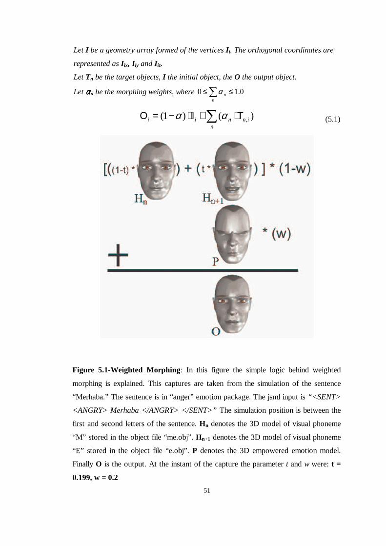
51
Let I be a geometry array formed of the vertices I i. The orthogonal coordinates are
represented as I ix, I iy and I iz.
Let Tn be the target objects, I the initial object, the O the output object.
Let ααααn be the morphing weights, where 0.10 ≤≤�n
nα
� Τ⋅+Ι⋅−=Οn
innii )()1( ,αα (5.1)
Figure 5.1-Weighted Morphing: In this figure the simple logic behind weighted
morphing is explained. This captures are taken from the simulation of the sentence
“Merhaba.” The sentence is in “anger” emotion package. The jsml input is “ <SENT>
<ANGRY> Merhaba </ANGRY> </SENT>” The simulation position is between the
first and second letters of the sentence. Hn denotes the 3D model of visual phoneme
“M” stored in the object file “me.obj” . Hn+1 denotes the 3D model of visual phoneme
“E” stored in the object file “e.obj” . P denotes the 3D empowered emotion model.
Finally O is the output. At the instant of the capture the parameter t and w were: t =
0.199, w = 0.2
52
An example of this weighted morphing is seen in Figure 5.1. The main problem of
weighted morphing is as the number of morph targets increase, weight of each target
decrease and the affect of these morph events become less evident in the final result.
Let’s give an example of morphing animation of speech with one single emotion.
The speech requires lip motion that is morphing of visual phonemes to each other in
time. But if you require a smiling lip motion in speech you need to morph the whole
animation with an emotion model corresponding to smiling. Let’s assume that the
total lip motion sequence is weighted by the real number w, where 0<w<1. Then
naturally the emotion model will be weighted with 1-w. If w is very close to 1 then
the emotion will be very insignificant. On the other hand as we decrease w, the
weight of emotion increases but the weight of lip motion sequence decreases and the
animation quality of the lip motion decreases too. In other words the animation loses
its understandability. To avoid this phenomenon two methods can be described in lip
motion morphing.
Segmented morphing: Segmented morphing allows us to morph separate areas of the
face individually. The morphing of the brows does not affect the morphing weight
around the lips. Segmented morphing has two advantages over straight morphing; the
ability to build a large number of expressions from a smaller set of targets and the
ability to animate changing expressions while the character is talking. If it is
somehow difficult to segment the model there is another method for the same
purpose.
Empowered emotion key-frame poses: In this method the model is not segmented.
The interpolation algorithm works for the whole model. But in this method instead of
using traditional key-frame poses for the emotion models we use empowered models.
To better understand this method let us return back to our question. The main
problem was that as the weighting increases the speech lip motion becomes
insignificant. In this method the lip motion weight is detained at a considerable value
like %80 or more. The remaining %20 or less weight is used for the emotion models.
Unfortunately %20 is a low weight with which the emotion of face will be
insignificant. Instead of using traditional emotion models we use empowered
emotion models. A traditional emotion model has the 3D shape of the face having an
emotion as illustrated in Figure 5.3. But empowered emotion model is somehow
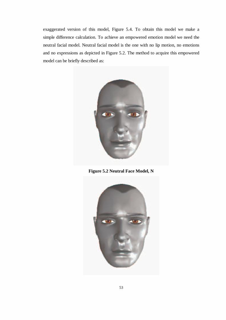
53
exaggerated version of this model, Figure 5.4. To obtain this model we make a
simple difference calculation. To achieve an empowered emotion model we need the
neutral facial model. Neutral facial model is the one with no lip motion, no emotions
and no expressions as depicted in Figure 5.2. The method to acquire this empowered
model can be briefly described as:
Figure 5.2 Neutral Face Model, N
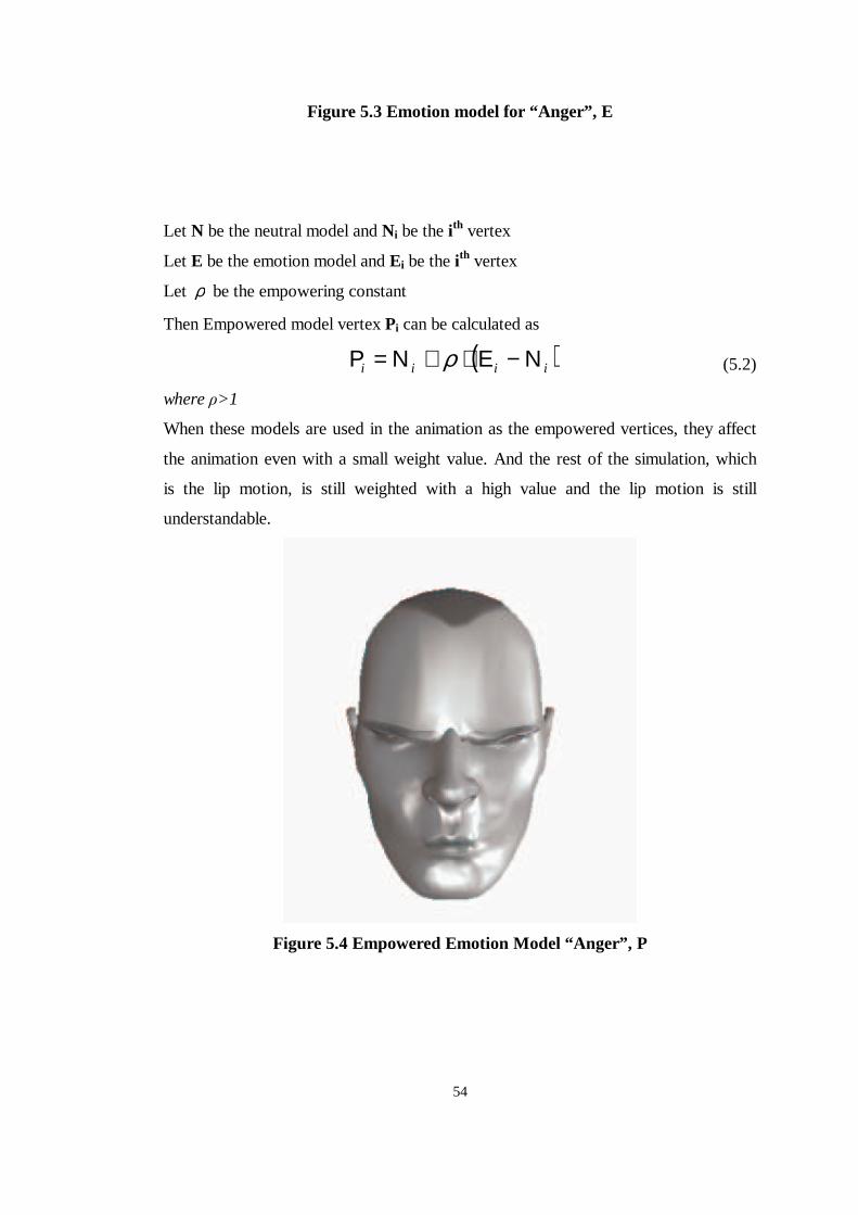
54
Figure 5.3 Emotion model for “ Anger” , E
Let N be the neutral model and Ni be the i th vertex
Let E be the emotion model and Ei be the i th vertex
Let ρ be the empowering constant
Then Empowered model vertex Pi can be calculated as
( )iiii Ν−Ε⋅+Ν=Ρ ρ (5.2)
where �>1
When these models are used in the animation as the empowered vertices, they affect
the animation even with a small weight value. And the rest of the simulation, which
is the lip motion, is still weighted with a high value and the lip motion is still
understandable.
Figure 5.4 Empowered Emotion Model “ Anger” , P
55
Actually this method was the method we used for our simulation. We simply chose
the empowering constant � as 3. The results can be seen, in Chapter 6 and in
Appendix C.
5.1.1 Mapping Turkish visual phonemes to Turkish letters.
As we have previously discussed for morphing animation we need the suitable set of
the models that we want to morph. For lip motion in speech, we must determine
some base models to morph. During lip motion of speech what kind of motion we do
or what base shapes the face takes are the essential questions we should answer. For
simulation of a language actually, taking the visual phonemes as the base models is
the most efficient way. With this method, the order of the animation is designed due
to the structure of the sentence. The explanation of this design is explained in the
next subsection.
In this thesis we have used the Turkish visual phonemes as the base set of models for
our lip motion animation for Turkish language. In order to obtain these base models,
different techniques can be used. Simply using 3D modeling software to design the
3D visual phonemes according to the information given in Chapter 3 is sufficient.
But if we want to use our own talking head models, or if we do not have such a 3D
design software we may use a 3D reconstruction device. This can be laser-scanning
device or a vision based calibrated camera view system [Mülayim 2002]. Whatever
the system is, before starting this animation we have to use a set of 3D face models
for Turkish visual phonemes.
We have acquired the 3D models using a 3D modeling software. The screen captures
of the entire models can be seen in Appendix B.
We have used totally 53 3D models. 36 models for the Turkish visual phonemes, 6
models for the empowered emotion models, 10 models for random facial mimics,
like blinking etc, and one single neutral model. Some of the letters are mapped into
the same model, like the letter ‘v’ and ‘ f’ . Moreover for some of the letters, it is
needed to use more than one model. The reason for this is based on the structure of
Turkish speech. For the letter ‘m’ in the word ‘mor’ and in the word ‘mert’ we have
used different models. The reason for this is explained in detail in the next
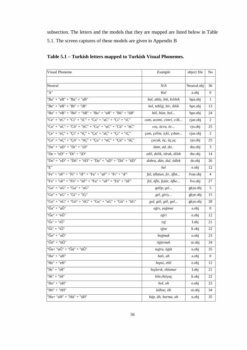
56
subsection. The letters and the models that they are mapped are listed below in Table
5.1. The screen captures of these models are given in Appendix B
Table 5.1 – Turkish letters mapped to Turkish Visual Phonemes.
Visual Phoneme Example object file No
Neutral N/A Neutral.obj 36
"A" Kal a.obj 0
"Ba" + "aB" + "Ba" + "aB" bal, abla, bık, kılıbık bpa.obj 1
"Be" + "eB" + "Bi" + "iB" bel, tebli�, bir, iblik bpe.obj 13
"Bo" + "oB" + "Bö" + "öB" + "Bu" + "uB" + "Bü" + "üB" böl, büst, bol... bpo.obj 24
"Ce" + "eC" + "Ci" + "iC" + "Ca" + "aC" + "Cı" + "ıC" cam, acemi, cimri, cılk... cjae.obj 2
"Co" + "oC" + "Cö" + "öC" + "Cu" + "uC" + "Cü" + "üC" co�, ücra, öc... cjo.obj 25
"Çe" + "eÇ" + "Çi" + "iÇ" + "Ça" + "aÇ" + "Çı" + "ıÇ" çam, çelim, içki, çıban... cjae.obj 2
"Ço" + "oÇ" + "Çö" + "öÇ" + "Çu" + "uÇ" + "Çü" + "üÇ" çocuk, öç, üç,uç cjo.obj 25
"Da" + "aD" + "Dı" + "ıD" dam, ad, dıt.. dta.obj 3
"De + "eD" + "Di" + "iD" edil, delik, idrak, dilek dte.obj 14
"Do" + "oD" + "Dö" + "öD" + "Du" + "uD" + "Dü" + "üD" dobra, dün, dul, ödlek do.obj 26
"E" kel e.obj 12
"Fe" + "eF" + "Fi" + "iF" + "Fa" + "aF" + "Fı" + "ıF" fal, eflatun, fır, iffet... fvae.obj 4
"Fo" + "oF" + "Fö" + "öF" + "Fu" + "uF" + "Fü" + "üF" fol, üfle, futür, öfke... fvo.obj 27
"Ga" + "aG" + "Ga" + "aG" galip, gıl... gkya.obj 5
"Ge" + "eG" + "Gi" + "iG" gel, giri�... gkye.obj 15
"Go" + "oG" + "Gö" + "öG" + "Gu" + "uG" + "Gü" + "üG" gol, göl, gül, gul... gkyo.obj 28
"�a" + "a�" a�rı, ya�mur a.obj 0
"�e" + "e�" e�ri e.obj 12
"�ı" + "ı�" tı� I.obj 21
"�i" + "i�" i�ne Ii.obj 22
"�o" + "o�" bo�mak o.obj 23
"�ö" + "ö�" ö�ürmek oi.obj 34
"�u+ "u�" + "�ü" + "ü�" tu�ra, ö�üt u.obj 35
"Ha" + "aH" halı, ah a.obj 0
"He" + "eH" hepsi, ehli e.obj 12
"Hı" + "ıH" hıçkırık, ıhlamur I.obj 21
"Hi" + "iH" hile,ihtiyaç Ii.obj 22
"Ho" + "oH" hol, oh o.obj 23
"Hö" + "öH" köhne, öh oi.obj 34
"Hu+ "uH" + "Hü" + "üH" hüp, üh, hurma, uh u.obj 35
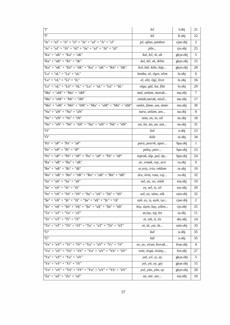
57
"I" kıl I.obj 21
"�" kil Ii.obj 22
"Je" + "eJ" + "Ji" + "iJ" + "Ja" + "aJ" + "Jı" + "ıJ" jel, ajlan, jambon cjae.obj 2
"Jo" + "oJ" + "Jö" + "öJ" + "Ju" + "uJ" + "Jü" + "üJ" jöle... cjo.obj 25
"Ka" + "aK" + "Ka" + "aK" kal, kıl, ık, ak gkya.obj 5
"Ke" + "eK" + "Ki" + "iK" kel, kil, ek, iklim gkye.obj 15
"Ko" + "oK" + "Kö" + "öK" + "Ku" + "uK" + "Kü" + "üK" kol, kül, köle, küp... gkyo.obj 28
"La" + "aL" + "La" + "aL" lamba, al, ılgın, alım la.obj 6
"Le" + "eL" + "Li" + "iL" el, elit, ilgi, liret le.obj 16
"Lo" + "oL" + "Lö" + "öL" + "Lu" + "uL" + "Lü" + "üL" olgu, gül, lut, flüt lo.obj 29
"Ma" + "aM" + "Ma" + "aM" mal, anlam, mızrak... ma.obj 7
"Me" + "eM" + "Mi" + "iM" emlak,merak, misil... me.obj 17
"Mo" + "oM" + "Mö" + "öM" + "Mu" + "uM" + "Mü" + "üM" omlet, füme, um, ömür mo.obj 30
"Na" + "aN" + "Na" + "aN" nara, anlam, anı... na.obj 8
"Ne" + "eN" + "Ni" + "iN" nem, en, in, nil ne.obj 18
"No" + "oN" + "Nö" + "öN" + "Nu" + "uN" + "Nü" + "üN" on, ön, ün, un, not... no.obj 31
"O" kol o.obj 23
"Ö" köle oi.obj 34
"Pa" + "aP" + "Pa" + "aP" para, pısırık, apar... bpa.obj 1
"Pe" + "eP" + "Pi" + "iP" pelo�, pıtır... bpe.obj 13
"Po" + "oP" + "Pö" + "öP" + "Pu" + "uP" + "Pü" + "üP" toprak, tüp, pul, öp... bpo.obj 24
"Ra" + "aR" + "Ra" + "aR" ar, ırmak, ray, arıt ra.obj 9
"Re" + "eR" + "Ri" + "iR" er,eri�, irin, reklam re.obj 19
"Ro" + "oR" + "Rö" + "öR" + "Ru" + "uR" + "Rü" + "üR" üre, örtü, rota, ruj... ro.obj 32
"Sa" + "aS" + "Sa" + "aS" sal, as, ısı, ıslak sza.obj 10
"Se" + "eS" + "Si" + "iS" es, sel, is, sil sze.obj 20
"So" + "oS" + "Sö" + "öS" + "Su" + "uS" + "Sü" + "üS" sol, us, süne, sök szto.obj 32
"�e" + "e�" + "�i" + "i�" + "�a" + "a�" + "�ı" + "ı�" a�k, e�, i�, a�ık, i�e... cjae.obj 2
"�o" + "o�" + "�ö" + "ö�" + "�u" + "u�" + "�ü" + "ü�" ko�, ü�en, ku�, �ölen... cjo.obj 25
"Ta" + "aT" + "Ta" + "aT" at,tay, tı�, kıt ta.obj 11
"Te" + "eT" + "Ti" + "iT" et, tek, it, tiz dte.obj 14
"To" + "oT" + "Tö" + "öT" + "Tu" + "uT" + "Tü" + "üT" ot, üt, �ut, öt... szto.obj 33
"U" kul u.obj 35
"Ü" kül u.obj 35
"Ve" + "eV" + "Vi" + "iV" + "Va" + "aV" + "Vı" + "ıV" ev, av, viran, kıvrak... fvae.obj 4
"Vo" + "oV" + "Vö" + "öV" + "Vu" + "uV" + "Vü" + "üV" vole, övgü, övünç... fvo.obj 27
"Ya" + "aY" + "Ya" + "aY" yal, yıl, ıy, ay gkya.obj 5
"Ye" + "eY" + "Yi" + "iY" yel, yit, ey, giy gkye.obj 15
"Yo" + "oY" + "Yö" + "öY" + "Yu" + "uY" + "Yü" + "üY" yol, yün, yön, uy gkyo.obj 28
"Za" + "aZ" + "Za" + "aZ" az, zar, azı... sza.obj 10
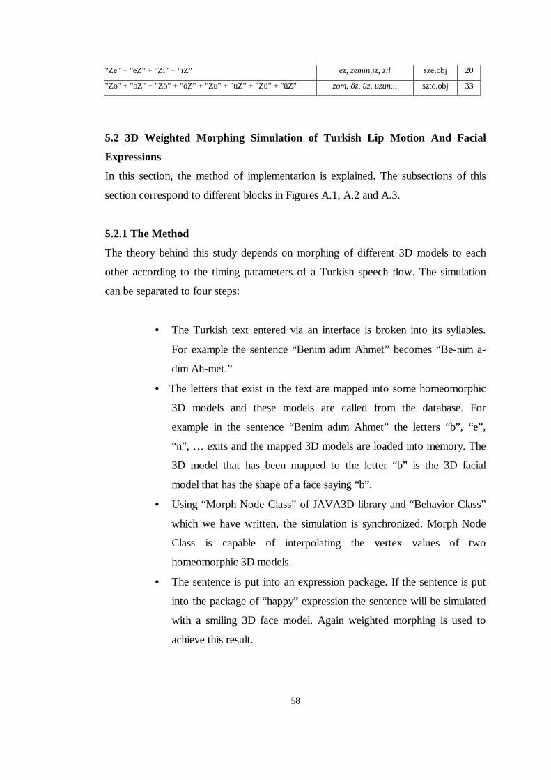
58
"Ze" + "eZ" + "Zi" + "iZ" ez, zemin,iz, zil sze.obj 20
"Zo" + "oZ" + "Zö" + "öZ" + "Zu" + "uZ" + "Zü" + "üZ" zom, öz, üz, uzun... szto.obj 33
5.2 3D Weighted Morphing Simulation of Turkish L ip Motion And Facial
Expressions
In this section, the method of implementation is explained. The subsections of this
section correspond to different blocks in Figures A.1, A.2 and A.3.
5.2.1 The Method
The theory behind this study depends on morphing of different 3D models to each
other according to the timing parameters of a Turkish speech flow. The simulation
can be separated to four steps:
• The Turkish text entered via an interface is broken into its syllables.
For example the sentence “Benim adım Ahmet” becomes “Be-nim a-
dım Ah-met.”
• The letters that exist in the text are mapped into some homeomorphic
3D models and these models are called from the database. For
example in the sentence “Benim adım Ahmet” the letters “b” , “e” ,
“n” , … exits and the mapped 3D models are loaded into memory. The
3D model that has been mapped to the letter “b” is the 3D facial
model that has the shape of a face saying “b” .
• Using “Morph Node Class” of JAVA3D library and “Behavior Class”
which we have written, the simulation is synchronized. Morph Node
Class is capable of interpolating the vertex values of two
homeomorphic 3D models.
• The sentence is put into an expression package. If the sentence is put
into the package of “happy” expression the sentence will be simulated
with a smiling 3D face model. Again weighted morphing is used to
achieve this result.
59
5.2.2 Extraction of Turkish Syllables
In Turkish, syllables correspond to voices we make with a single movement of our
lips. Like every other alphabet, Turkish alphabet consists of consonants and vowels.
By definition, a Turkish syllable consists of a single vowel and n number of
consonants where n=0,1,2,3. The list of regular Turkish syllables is shown below.
Let ‘a’ denote a “ vowel” and ‘b’ denote a “ consonant” :
• a “ u�ur”
• ab “ erdem”
• ba “ kalem”
• abb “ ilkokul”
• bab “ ya�mur”
• babb “ farklı”
Since the focal objective of our study is not the extraction of Turkish syllables from
written text, we have used an uncomplicated algorithm in extraction of syllables.
First of all our algorithm assumes that the Turkish text does not have any syntax
error and is composed of only Turkish words. The algorithm can be summarized as:
• Partitioning of the text into sentences
• Partitioning of the sentences into words
• Partitioning of the words into syllables
To partition the text into sentences we have search for the full stops ’ .’ , the question
marks ‘ ?’ and the exclamation marks ‘ !’ .
To partition the sentences we have searched for the spaces between words. As
expected our algorithm assumes that only one space exists between two words in a
sentence.
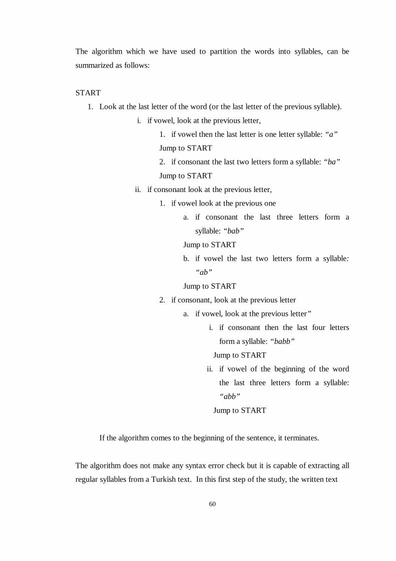
60
The algorithm which we have used to partition the words into syllables, can be
summarized as follows:
START
1. Look at the last letter of the word (or the last letter of the previous syllable).
i. if vowel, look at the previous letter,
1. if vowel then the last letter is one letter syllable: “ a”
Jump to START
2. if consonant the last two letters form a syllable: “ ba”
Jump to START
ii. if consonant look at the previous letter,
1. if vowel look at the previous one
a. if consonant the last three letters form a
syllable: “ bab”
Jump to START
b. if vowel the last two letters form a syllable:
“ ab”
Jump to START
2. if consonant, look at the previous letter
a. if vowel, look at the previous letter”
i. if consonant then the last four letters
form a syllable: “ babb”
Jump to START
ii. if vowel of the beginning of the word
the last three letters form a syllable:
“ abb”
Jump to START
If the algorithm comes to the beginning of the sentence, it terminates.
The algorithm does not make any syntax error check but it is capable of extracting all
regular syllables from a Turkish text. In this first step of the study, the written text
61
“ Merhaba, benim adım Erdem Akagündüz.”
becomes
“mer-ha-ba, be-nim a-dım er-dem a-ka-gün-düz.”
5.2.3 Mapping of the letters to 3D models.
In this step, using the information of the edited text, we have mapped the letters of
the sentences to the homeomorphic 3D models in our database. Considering that the
word “ Merhaba” became “ mer-ha-ba” , the letters of this word is ready to map to
the 3D models. To better understand this step we should take a closer look on the
movement of our lips, tongue and mouth when we are speaking Turkish.
As we have mentioned before, syllables correspond to voices we make with a single
movement of our lips, tongue or mouth. For example in the word “mer-ha-ba” the
syllable “ mer” is pronounced with a single effort. When we are saying “mer” , first
our mouth takes the shape of saying the letter “m”. After that we shape our mouth to
say “e” and finally end the syllable with moving our tongue to say “r” . Therefore we
can assume that there exist three main states of our mouth when we say “ mer” ; the
state of our mouth when we say “m”, the state of our mouth when we say “e” and the
state of our mouth when we say “r” . We can visualize the process of saying “ mer” ,
just like morphing of our mouth from “m” to “e” and “e” to “r” . Consequently with
an idea similar to key-framing, which is mainly used in 3D animation, three 3D
Human face models, which have the shapes of saying “m”, “e” and “r” , can be
morphed to each other in appropriate order and proper timing, and they can form the
3D animation of a face saying “ mer” .
As expected all syllables corresponded to voices we have made with a single effort.
Furthermore we have realized that the single vowel of syllable affected pronunciation
of all of the consonants of that syllable. To understand this phenomenon in detail
let’s look at two Turkish words: “ mor” and “ mert” .
As we have explained above the word “ mor” can be simulated by morphing of “m”
to “o” and “o” to “r” . Similarly the word “ mert” can be simulated by morphing of
“m” to “e” , “e” to “r” and “r” to “t” . Can we model the letter “m” in the word “mor”
and the letter “m” in the word “mert” with the same 3D human face model? From
our examinations from the video sequences, the answer seems to be negative. When
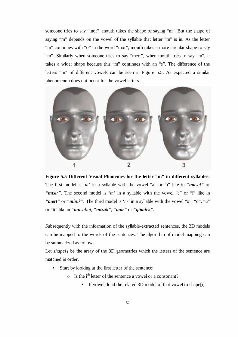
62
someone tries to say “mor” , mouth takes the shape of saying “m”. But the shape of
saying “m” depends on the vowel of the syllable that letter “m” is in. As the letter
“m” continues with “o” in the word “mor” , mouth takes a more circular shape to say
“m”. Similarly when someone tries to say “mert” , when mouth tries to say “m”, it
takes a wider shape because this “m” continues with an “e” . The difference of the
letters “m” of different vowels can be seen in Figure 5.5. As expected a similar
phenomenon does not occur for the vowel letters.
Figure 5.5 Different Visual Phonemes for the letter “ m” in different syllables:
The first model is ‘m’ in a syllable with the vowel “a” or “ı” like in “ masal” or
“ mısır” . The second model is ‘m’ in a syllable with the vowel “e” or “ i” like in
“ mert” or “ minik” . The third model is ‘m’ in a syllable with the vowel “o” , “ö” , “u”
or “ü” like in “ musallat, “ müzik” , “ mor” or “ gömlek” .
Subsequently with the information of the syllable-extracted sentences, the 3D models
can be mapped to the words of the sentences. The algorithm of model mapping can
be summarized as follows:
Let shape[ ] be the array of the 3D geometries which the letters of the sentence are
matched in order.
• Start by looking at the first letter of the sentence:
o Is the i th letter of the sentence a vowel or a consonant?
��If vowel, load the related 3D model of that vowel to shape[i]
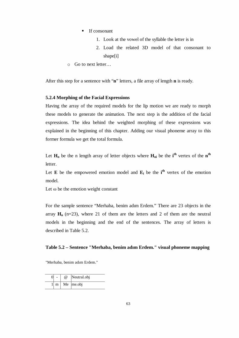
63
��If consonant
1. Look at the vowel of the syllable the letter is in
2. Load the related 3D model of that consonant to
shape[i]
o Go to next letter…
After this step for a sentence with “n” letters, a file array of length n is ready.
5.2.4 Morphing of the Facial Expressions
Having the array of the required models for the lip motion we are ready to morph
these models to generate the animation. The next step is the addition of the facial
expressions. The idea behind the weighted morphing of these expressions was
explained in the beginning of this chapter. Adding our visual phoneme array to this
former formula we get the total formula.
Let Hn be the n length array of letter objects where Hni be the i th vertex of the nth
letter.
Let E be the empowered emotion model and Ei be the i th vertex of the emotion
model.
Let � be the emotion weight constant
For the sample sentence “Merhaba, benim adım Erdem.” There are 23 objects in the
array Hn (n=23), where 21 of them are the letters and 2 of them are the neutral
models in the beginning and the end of the sentences. The array of letters is
described in Table 5.2.
Table 5.2 – Sentence " Merhaba, benim adım Erdem." visual phoneme mapping
"Merhaba, benim adım Erdem."
0 - @ Neutral.obj
1 m Me me.obj
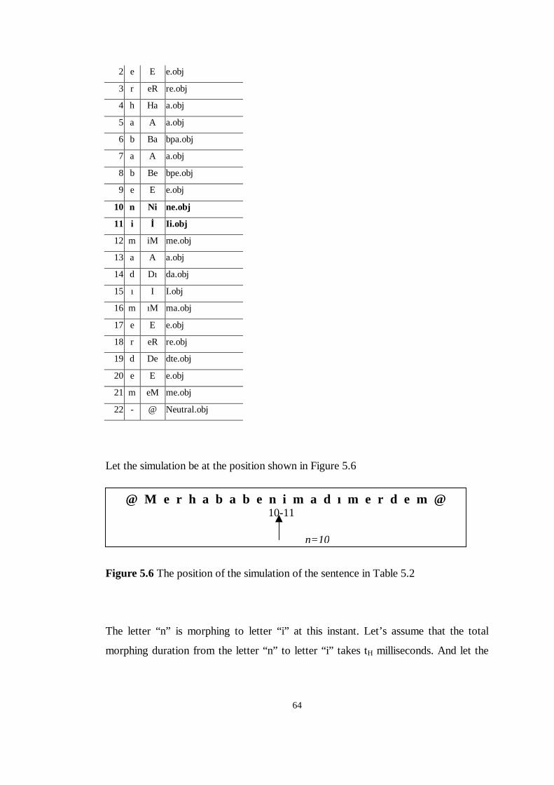
64
2 e E e.obj
3 r eR re.obj
4 h Ha a.obj
5 a A a.obj
6 b Ba bpa.obj
7 a A a.obj
8 b Be bpe.obj
9 e E e.obj
10 n Ni ne.obj
11 i � I i.obj
12 m iM me.obj
13 a A a.obj
14 d Dı da.obj
15 ı I I.obj
16 m ıM ma.obj
17 e E e.obj
18 r eR re.obj
19 d De dte.obj
20 e E e.obj
21 m eM me.obj
22 - @ Neutral.obj
Let the simulation be at the position shown in Figure 5.6
Figure 5.6 The position of the simulation of the sentence in Table 5.2
The letter “n” is morphing to letter “ i” at this instant. Let’s assume that the total
morphing duration from the letter “n” to letter “ i” takes tH milliseconds. And let the
@ M e r h a b a b e n i m a d ı m e r d e m @ 10-11
n=10
65
parameter t be H
0
t
tt = where t0 is any time instant inside the morphing duration of
letter “n” to letter “ i” . 10 ≤≤ t
n=10
Then at time t0 the Output object O, which has the vertices Oi is calculated as:
( ) ( ) ( )( )[ ] iinini tt Ε⋅+−⋅Η+⋅Η⋅−=Ο + ωω 11 ,1, (5.3)
The above formula depicts the main calculation algorithm of our simulation. But in
fact the actual formula is a bit extended. Different emotions may be simulated in one
sentence. The first word may be in a “smiling” emotion package, where the second
word has the “surprise” emotion package. Between the first and the second words as
the emotion object E changes, the simulation experiences a non-smooth flow. In
order to avoid this phenomenon in our algorithm, instead of using one single emotion
object E, we have used two objects, namely Epre the previous emotion and Enext the
next emotion. Then again for the same Hn, E, t and ωωωω the formulation becomes:
( ) ( ) ( )( )[ ] ( )( )[ ]inextipreinini tttt ,,,1, 111 Ε⋅+Ε⋅−⋅+−⋅Η+⋅Η⋅−=Ο + ωω (5.4)
So when the previous and the next emotions are different a smooth transform is
observed between the emotions and the lip motion.
The above formula summarizes the overall animation sequence. The screen capture
results can be seen in Figure 5.7. Also animation sequences can be viewed as movie
clip in Appendix C.
5.2.5 Speech Markup Language Implementation
A speech markup language allows applications to annotate text with additional
information that can improve the quality and naturalness of synthesized speech or lip
motion. In this thesis lip motion is synchronized and morphed with emotions and
66
synchronized with speech. Since the input was text and the output is lip motion with
emotions and synthesized speech we needed a markup language, which should
handle emotions, delay and similar natural speech event during simulation. We have
constructed the whole simulation in java programming language [SUN JAVA]. In
order to build the 3D virtual world we have used JAVA3D API [SUN JAVA3D]. In
addition to 3D lip motion simulation we have synchronized this animation with
synthesized speech. We have used Turkish speech synthesis engine of G.V.Z
company [G.V.Z]. As an interface between this speech engine and our simulation
program, we have used CloudGarden Java Speech API [CloudGarden JSAPI]. Since
our entire application is written in JAVA programming language, we have chosen
JAVA Speech Markup Language [JSML] to use in our application.
JSML has been developed to support as many types of applications as possible, and
to support text markup in many different languages. It has certain structural rules.
Container elements, empty elements, white spaces and etc are defined by some
specific language rules. More importantly some default tags exist for this markup
language. But new tags can be defined for certain applications.
For our application we simply needed to use SENT tag and defined our basic six
emotion tags, namely happiness, fear, sadness, surprise, anger and disgust. So
according to JSML format rules a sample input text to our application was like:
“ <SENT>Animasyon programımız, <SAD>hüzün</SAD>
<HAPPY>sevinç</HAPPY> <ANGER>sinir</ANGER> gibi duyguları aynı cümle
içinde simüle edebilmektedir.</SENT>”
This is a sample input text to our application. This animation is given in Appendix C
as a movie clip. We have written a simple JSML parser code to parse the markup
text. Details of this code can be found in Appendix A together with details of the
simulation software. Accordingly the markup tag names for six emotions are:
Table 5.3 – JSML Emotion tags.
Anger: <ANGRY>jsml text</ANGRY>
Fear: <AFRAID>jsml text</AFRAID>
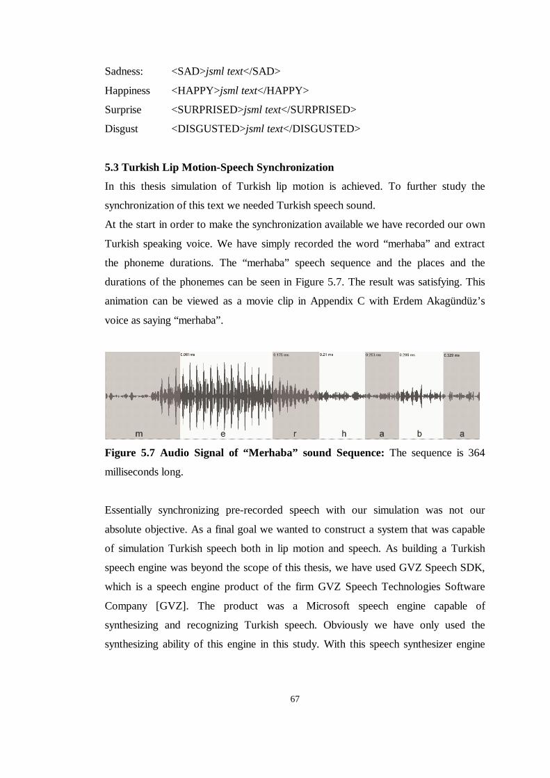
67
Sadness: <SAD>jsml text</SAD>
Happiness <HAPPY>jsml text</HAPPY>
Surprise <SURPRISED>jsml text</SURPRISED>
Disgust <DISGUSTED>jsml text</DISGUSTED>
5.3 Turkish L ip Motion-Speech Synchronization
In this thesis simulation of Turkish lip motion is achieved. To further study the
synchronization of this text we needed Turkish speech sound.
At the start in order to make the synchronization available we have recorded our own
Turkish speaking voice. We have simply recorded the word “merhaba” and extract
the phoneme durations. The “merhaba” speech sequence and the places and the
durations of the phonemes can be seen in Figure 5.7. The result was satisfying. This
animation can be viewed as a movie clip in Appendix C with Erdem Akagündüz’s
voice as saying “merhaba”.
Figure 5.7 Audio Signal of “ Merhaba” sound Sequence: The sequence is 364
milliseconds long.
Essentially synchronizing pre-recorded speech with our simulation was not our
absolute objective. As a final goal we wanted to construct a system that was capable
of simulation Turkish speech both in lip motion and speech. As building a Turkish
speech engine was beyond the scope of this thesis, we have used GVZ Speech SDK,
which is a speech engine product of the firm GVZ Speech Technologies Software
Company [GVZ]. The product was a Microsoft speech engine capable of
synthesizing and recognizing Turkish speech. Obviously we have only used the
synthesizing ability of this engine in this study. With this speech synthesizer engine
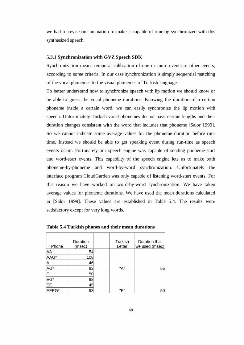
68
we had to revise our animation to make it capable of running synchronized with this
synthesized speech.
5.3.1 Synchronization with GVZ Speech SDK
Synchronization means temporal calibration of one or more events to other events,
according to some criteria. In our case synchronization is simply sequential matching
of the vocal phonemes to the visual phonemes of Turkish language.
To better understand how to synchronize speech with lip motion we should know or
be able to guess the vocal phoneme durations. Knowing the duration of a certain
phoneme inside a certain word, we can easily synchronize the lip motion with
speech. Unfortunately Turkish vocal phonemes do not have certain lengths and their
duration changes consistent with the word that includes that phoneme [Salor 1999].
So we cannot indicate some average values for the phoneme duration before run-
time. Instead we should be able to get speaking event during run-time as speech
events occur. Fortunately our speech engine was capable of sending phoneme-start
and word-start events. This capability of the speech engine lets us to make both
phoneme-by-phoneme and word-by-word synchronization. Unfortunately the
interface program CloudGarden was only capable of listening word-start events. For
this reason we have worked on word-by-word synchronization. We have taken
average values for phoneme durations. We have used the mean durations calculated
in [Salor 1999]. These values are established in Table 5.4. The results were
satisfactory except for very long words.
Table 5.4 Turkish phones and their mean durations
Phone Duration (msec)
Turkish Letter
Duration that we used (msec)
AA 54 AAG* 108 A 46 AG* 92 "A" 55 E 50 EG* 98 EE 45 EEEG* 93 "E" 50
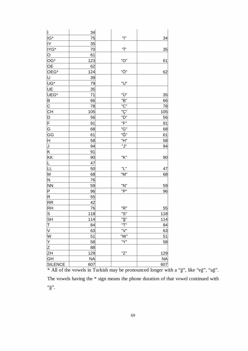
69
I 34 IG* 75 "I" 34 IY 35 IYG* 70 "�" 35 O 61 OG* 123 "O" 61 OE 62 OEG* 124 "Ö" 62 U 39 UG* 79 "U" UE 35 UEG* 71 "Ü" 35 B 66 "B" 66 C 78 "C" 78 CH 105 "Ç" 105 D 56 "D" 56 F 91 "F" 91 G 68 "G" 68 GG 61 "�" 61 H 58 "H" 58 J 94 "J" 94 K 91 KK 90 "K" 90 L 47 LL 50 "L" 47 M 68 "M" 68 N 76 NN 59 "N" 59 P 96 "P" 96 R 55 RR 42 RH 76 "R" 55 S 118 "S" 118 SH 114 "�" 114 T 84 "T" 84 V 63 "V" 63 W 51 "W" 51 Y 58 "Y" 58 Z 88 ZH 129 "Z" 129 GH NA NA SILENCE 607 607 * All of the vowels in Turkish may be pronounced longer with a “�” , like “e�” , “a�” .
The vowels having the * sign means the phone duration of that vowel continued with
“�” .
70
Apparently in Turkish, the phone durations may differ for a letter in different words.
For this reason one letter may have different pronunciation types. There is open “a”
and closed “a” in Turkish, like in ”ka�ıt” and “kal” . The letter “a” is pronounced
differently and has different duration. We have taken the smallest mean duration for
a word in our application.
The CloudGarden JAVA Speech API is able to send word-start events during speech
run-time. So we have changed our application in a way that it became able to wait for
the new word event to come before starting a new lip motion for the new word. As
the syllables and phonemes inside the words need synchronization, the timing issue
for our application was not completed. Inside the words we have used average values
for the phonemes. As we have discussed before using average values may cause
errors since the duration of phonemes may vary from word to word. But this error
inside the words was negligible because the error was cleared before each word-start
as word-start events were waited from the speech engine. The average values we
have used for these words are taken from the studies of Özgül Salor [Salor 1999].
The results are discussed in the next chapter and can be viewed as video clips in
Appendix C.
71
CHAPTER 6
RESULTS AND PERFORMANCE
In this chapter the output of this study is examined according to esthetic look,
understandability (usability) and software performance. Needless to say that all these
three criteria affect each other controversially, meaning each of them is a trade-off
for the other one. We will analyze the results of this study according to these
standards.
As this thesis was a study of creating a communication device, the usability or in
other words the understandability of this study was our primary concern. The
usability can be examined according to some technical properties of the output.
��Lip/Speech Synchronization
��Number of frames/seconds (frame rate) in the animation.
��Synthesized sound quality
Before examining these usability issues of the output of this study, we should
understand the trade-off we make. High software performance is required to obtain
high number of frames per second in the animation. Also synchronization of lip
motion with the synthesized speech requires high software performance. As the
system is working in real-time the overall output should be over a certain quality
concern to pass the usability standards.
72
6.1 L ip/Speech Synchronization
Actually synchronization quality is the primal concern of understandability. In
communication we humans are adapted to perfect synchronization of speech and lip
motion. The articulators we have defined in chapter 3 of the human system have
specific states in generating the speech sound. When some certain shapes taken by
these articulators produce the vocal sound, the visual and vocal phonemes are
synchronized naturally. When we try to say “a” our articulators, namely, lips, teeth,
palate and throat, take some shapes in order to produce the desired sound. This is the
natural way that the synchronization among visual and vocal phonemes happens. In
our virtual world things do not happen this way.
As we have explained in the previous chapters in our simulation, the systems that
produce the lip motion and the speech sound are definitely distinct. Lip motion is
created via the Java3D virtual engine, which uses OpenGL to use the video card
hardware to render the 3D scene. Java3D virtual engine is actuated via our Java code.
On the other hand the sound is produced via the Microsoft Speech engine named
“GVZ Levent16k” . The speech sound is triggered using this speech engine via the
CloudGarden Java Speech API interface in our Java code. Noticeably the two
sources of the synchronization are generated from two totally separate engines.
To synchronize these two separate engines we need a certain communication
protocol between the two sources. Fortunately Microsoft Speech Engines 4.x and 5.x
send some speech events during the simulation. Generally different events are thrown
when new words are to be synthesized or a new phoneme is in the event queue of the
speech engine output buffer. As we have previously stated, we have used a word-by-
word synchronization based system. In our code we have listened to the wordStarted
event thrown by the Speech Engine via the java Speech API interface. When a new
word started to be synthesized by the speech engine, we have triggered the
simulation. The results are captured in some movie clips and can be seen in
Appendix C.
According to our analysis if the software performance is low, somehow the CPU
usage of the software is very extreme and the synchronization experiences some lags.
The reason for this is that the word start events are thrown according to some speech
73
engine properties and if the processor usage is above some value then these event-
throwing durations may experience some lags. The processor load may increase
according to the size of JAVA3D window that is rendered. In Appendix C the results
can be analyzed according to rendering window size, the JSML input, the number of
frames per second and the captured movie clip of the simulation.
6.2 Number of frames / second
When the output object is an animation or a moving picture, one of the most
important performance issues is the number of frames per second of the animation.
Human visual system has a certain sampling rate, which enables it to realize 24
frames per second. Above this rate some images cannot be realized by the neural
system in conscious level. But psychologists insist that when frame rate is above 24
frames per seconds, human brain realizes these images in subconscious level.
However as an end user we comprehend high frame rate as a high quality animation.
In a 3D animation the frame rate is directly related to the processor usage. In other
words, the ratio between the number of operations the software system can
accomplish in one second and the number of operations needed to render one frame
and synthesize sound indicate the frame rate. In Appendix C the results can be
analyzed according to rendering window size, the JSML input, the number of frames
per second and the captured movie clip of the simulation.
6.3 Synthesized Sound Quality
Speech synthesis is the process of conversion of written text into spoken language. It
is also referred as text-to-speech (TTS) conversion. Like other computer-synthesized
events, TTS conversion is also a case of digital-to-analog conversion (DAC). Similar
to other DAC applications, TTS conversion has the attributes like resolution, etc. The
speech system that we used was GVZ Speech SDK, which is a speech engine product
of the firm GVZ Speech Technologies Software Company [GVZ]. The name of the
speech voice they have created was “Levent16k” . The engine is streaming, Multi-
Lingual and Microsoft SAPI 4, SAPI 5 compliant. Detailed features of this speech
engine can be reached from [GVZ]. The vocal results can be examined in the
captured movie clips in Appendix C.
74
6.4 Software Performance
Since the output of this study was a real-time rendered software application with
vocal synchronization, the software performance was one of our important concerns.
We have run this application in a computer with a Pentium® 4 CPU having a 2.00
GHz clock, DELL OPTIPLEX GX260 INTEL main board, 512 MB RAM and
NVIDIA GEForce2 MX/MX 400 video card.
For different window sizes the frame rates, CPU and Memory usage are given in
Appendix C.
As can be seen from appendix C, the CPU usage is always %100. This is a
processing issue of JAVA3D. We have experienced that a live scene of JAVA3D
rendered on screen takes CPU usage to %100.
Similarly as seen in Appendix C the memory usage is same for the entire samples.
The reason is that we have constructed a system using fixed size memory. The 3D
models are taken into memory for once. This let us construct a real-time speaker. The
memory requirements of the captures seen in Appendix C are approximately 267
MB. This doesn’t depend on how long the input JSML text is. This requirement only
depends on the number of vertices of the homeomorphic 3D model set.
As it can be seen in Appendix C, the frame rate is over 40 frames per second. This
rate is far more than what we need. With the given hardware and software
configuration such a rate is achieved. The rate falls with the window size very
slightly. Similarly the effect of speaking rate on frame rate is very slight but evident.
As the speaking rate increases, since the working load of the processor increase,
frame rate falls down vaguely. We think that this is an optimization issue of internal
JAVA3D engine
Since 3D rendering is a computationally difficult task, real time 3D animation
requires remarkable effort on optimization. Some optimization issues are presented
in [Alexa et al 1996]. We have used only one of their optimization issues. The
Java3D morph node interpolates all vertex coordinates, normal coordinates and
texture coordinates. Mark Alexa, et al proposes that only necessary coordinates can
be interpolated and others could be taken out of the morphing algorithm. As we are
using 3D facial models, the texture coordinates does not change. The model is
75
interpolated and in the end it is mapped to a texture. So if texture coordinates are not
interpolated in the morphing algorithm, much swiftness may be achieved in the
simulation.
Logically using low-resolution texture and low-resolution 3D models will result in
low esthetic quality but higher frame rates.
6.5 3D Esthetic model and animation quality
Since the output of this study is an animation, a moving picture, esthetic quality is
one of the important characteristics of the study. The characteristics of esthetic
quality would be the quality of the 3D model, the quality of the chosen 3D visual
phonemes and the quality and smoothness of the animation.
In this study we have acquired the 3D models from a 3D modeling software. But it is
important to note that this study is designed to work with any set of homeomorphic
3D models, which represent the visual phonemes of Turkish language. This property
of the system enables us to work with any set of 3D models.
The models we have used were detailed models having 20784 numbers of vertices.
But artistically the model was a cartoon face and the texture was low detailed. So the
animation was a high detailed cartoon animation.
With a 3D model set, which has more detailed texture coordinates; the esthetic
quality of the system might be tremendously increased. By using a high quality
capture system, high quality visual phonemes can be acquired and the system will be
similar to a real head animation more than a carton talking head. Actually this is our
nearest future study.
In addition using a high quality 3D modeling software for creation of the 3D
homeomorphic models, the esthetic results may be improved.
76
CHAPTER 7
CONCLUSIONS AND FUTURE STUDIES
In this thesis we analyzed a method for 3D animation of Turkish speech, human
facial expressions and synchronization with a Turkish Speech engine using JAVA
programming language, JAVA3D API and Java Speech API. We developed a 3D
animation model that was able to simulate Turkish speech together with visual and
audio components. To generate the simulation we have used OpenGL via JAVA3D
API classes and interfaces. Also we have used G.V.Z Speech Technology’s Turkish
Speech engine GVZ SDK for human voice synthesis. Using these two interfaces we
have constructed the animation and synchronization software in Java programming
language.
The implementation block system has JSML Turkish text input and it has the output
of real-time 3D Turkish speaker animation.
In order to model Turkish lip motion we have first defined the Turkish visual
phoneme by inspection. We have mapped all the letters of Turkish alphabet to a
single or multiple numbers of 3D visual phoneme models. In this mapping operation
we have taken the syllable structure of Turkish language in consideration. To extract
syllables from a Turkish sentence, we have defined an algorithm.
Finally we have synchronized the animation with synthesized Turkish speech on a
word-by-word synchronization basis. The simulation we have constructed can be
77
animated with any suitable set of 3D homeomorphic set of 3D models as we have
defined.
We have captured these animations with an external video camera from the computer
monitor. The reason we have used an external video camera instead of using
capturing software which could capture desktop events, was that we did not want our
software performance analysis to be affected from the processor load of this capture
application. We have represented these results. Through out the animations we have
achieved a frame rate over than 40 frames/seconds. We have constructed an
implementation software with a fixed size memory requirement of 267 MB. We have
used 3D homeomorphic models with 20784 vertices.
Even though the 3D morphing animation system we have proposed is not a new
system, as far as we know a simulation and synchronization system for real-time
Turkish speaker is a brand new study. Today’s communication devices are getting
complicated everyday. In every application humans need human-like
communication. Even today mail reading speech synthesizer applications and real
time facial animations are being used. But the usages of these applications are
limited to certain languages.
As the system we have proposed is simple, model-independent and implemental on
any software system we think that it can be used in many important applications.
Some of these applications can be listed as virtual chat machines with personalized
3D models and Turkish voices, a Turkish speaker as an interface for an artificial
intelligent system, Turkish speaker desktop applications etc. These studies happen to
be among our future study schedule in our Computer Vision and Intelligent Systems
Research Laboratory.
Another future study could be implementing this software to an embedded hardware
system, which could be utilized by cellular phones. So a visual Turkish speech
animating message service will be applicable in cellular phones
In addition to these future studies we think of constructing 3D homeomorphic model
sets compatible to this thesis. Using the calibrated camera system proposed by
[Mülayim 2002] we think of capturing the visual phonemes, emotion models and
Neutral models of different people, we plan to construct a library for our model-
selectable speaker applications.
78
REFERENCES
[Akagündüz, Halıcı 2003] Erdem Akagündüz, U�ur Halıcı. Simulation and
Synchronization of Human Facial Expressions and Lip Motion for Turkish Syllables,
TAINN 2003
[Alexa et. al. 1996] Marc Alexa, Johannes Behr, Wolfgang Müller. “The Morph
Node” Dramstadt University of Technology, GRIS
[Bilkent CTLP] CENTER FOR TURKISH LANGUAGE AND SPEECH
PROCESSING, http://www.nlp.cs.bilkent.edu.tr/
[CloudGarden JSAPI] www.cloudgarden.com
[Ekman 1975] Paul Ekman and Wallce V.Friesen, UNMASKING THE FACE – A
guide to recognizing emotions from facial clues
[Ergenç 1995] D. Ergenç, Konu�ma Dili ve Türkçenin Söyleni� Sözlü�ü Simurg,
Ankara 1995
[Ferner, Staubesand 1985] Helmut Ferner and Jochen Staubesand, Sobotta Human
Anatomy Atlas Volume 1, Turkish version 2.Edition by Prof.Dr. Kaplan Arıncı 1985
[Fleming, Dobbs 1999] Bill Fleming, Darris Dobbs, ANIMATING FACIAL
FEATURES AND EXPRESSIONS
[G.V.Z.] www.gvz.com.tr
[Kalra 1991] SMILE: Prem Kalra, Agelo Mangili, Nadia Magnenat-Thalmann,
Daniel Thalmann, A Multilayered Facial Animation System
79
[Magnetat- Thalmann N. 1988] Magnetat Thalman N, Primeau E, Thalmann D,
Abstract Muscle Action Procedures for Human Face Animation, The Visual
Computer, Vol.3, No.5, 1988
[MPEG-4 1998] International Standardization Organization (ISO) IO JTCI
SC29/WG11. MPEG-4, http://www.mpeg-4.com/, 1998.
[Mülayim 2002] Adem Ya�ar Mülayim, 3D Reconstruction of Rigid Objects From
Multiple Calibraed Views, Doctorate Thesis, 2002
[Parke, Waters 1996] Frederic I. Parke, Keith Waters, COMPUTER FACIAL
ANIMATION
[Platt, Badler 1981] S. Platt and N. Badler. Animating facial expressions. ACM
Computer Graphics (Proc. of SIGGRAPH'81), 15(3):245--252, 1981.
[Ricci 1973] A. A. Ricci. A constructive geometry for computer graphics. The
computer Journal, 16(2):157-160, May 1973
[Salor 1999] Özgül Salor, Signal Processing Aspects of Text-to-Speech Synthesizer
in Turkish, METU Master Thesis, 1999.
[SUN] Java Programming Language, www.sun.com
[VRML2.0 1996] The Virtual Reality Modeling Language Version 2.0,
http://vag.vrml.org/VRML2.0/FINAL August 1996.
[Waters 1987] Keith Waters. 1987. A muscle model for animating three-dimensional
facial expression. Computer Graphics, 21(4):17-24. 109
[Watt 1993] Alan Watt, 3D Computer Graphics, 2nd Edition, 1993
80
APPENDIX A
DETAILS OF THE SIMULATION SOFTWARE
As we have mentioned before, in this thesis we analyzed a method for 3D animation
of Turkish speech, human facial expressions and synchronization with a Turkish
Speech engine using JAVA programming language, JAVA3D API and Java Speech
API. The implementation software was written in JAVA language. In this chapter we
will analyze the block diagram of the total study.
The implementation can be divided into two parts, Figure A.1. The first part is the
parsing of the sentences. The input of the total system is Turkish JSML text. In the
first part this text is parsed and the emotion packages are detected for each word.
Moreover, the parsed sentenced is split into its syllables. In the end of the first part
we have the syllable extracted sentence and the word emotion array which carries the
emotion package information for each word, Figure A.2.
In the second part the syllable extracted sentence is broken into its letters, and the
visual phonemes are matched to the 3D visual phoneme letters. At the same time the
speech sound is synthesized. Finally the animation is run synchronized with the
speech sound, Figure A.3.
These steps are explained in detail below.
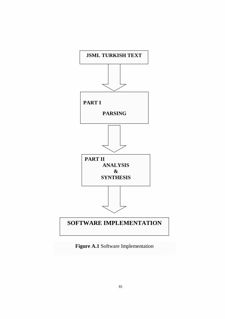
81
PART I I ANALYSIS
& SYNTHESIS
SOFTWARE IMPLEMENTATION
JSML TURKISH TEXT
PART I
PARSING
Figure A.1 Software Implementation
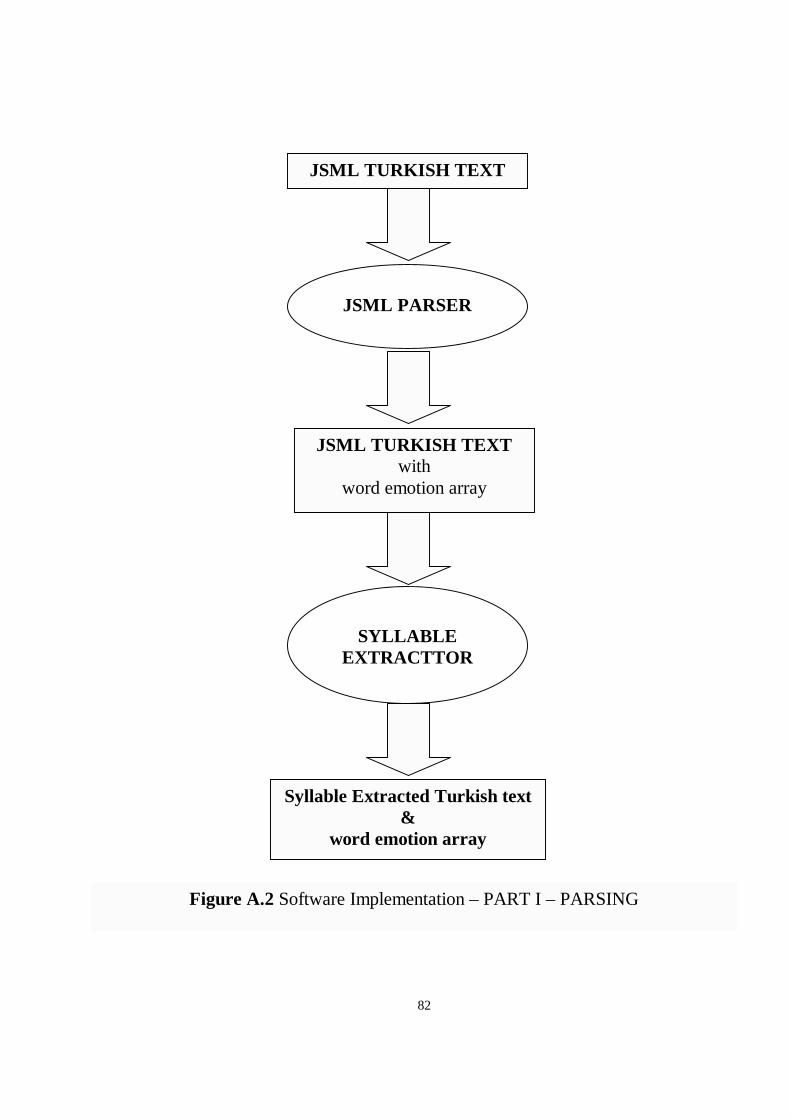
82
JSML PARSER
JSML TURKISH TEXT with
word emotion array
SYLLABLE EXTRACTTOR
Syllable Extracted Turkish text &
word emotion ar ray
JSML TURKISH TEXT
Figure A.2 Software Implementation – PART I – PARSING
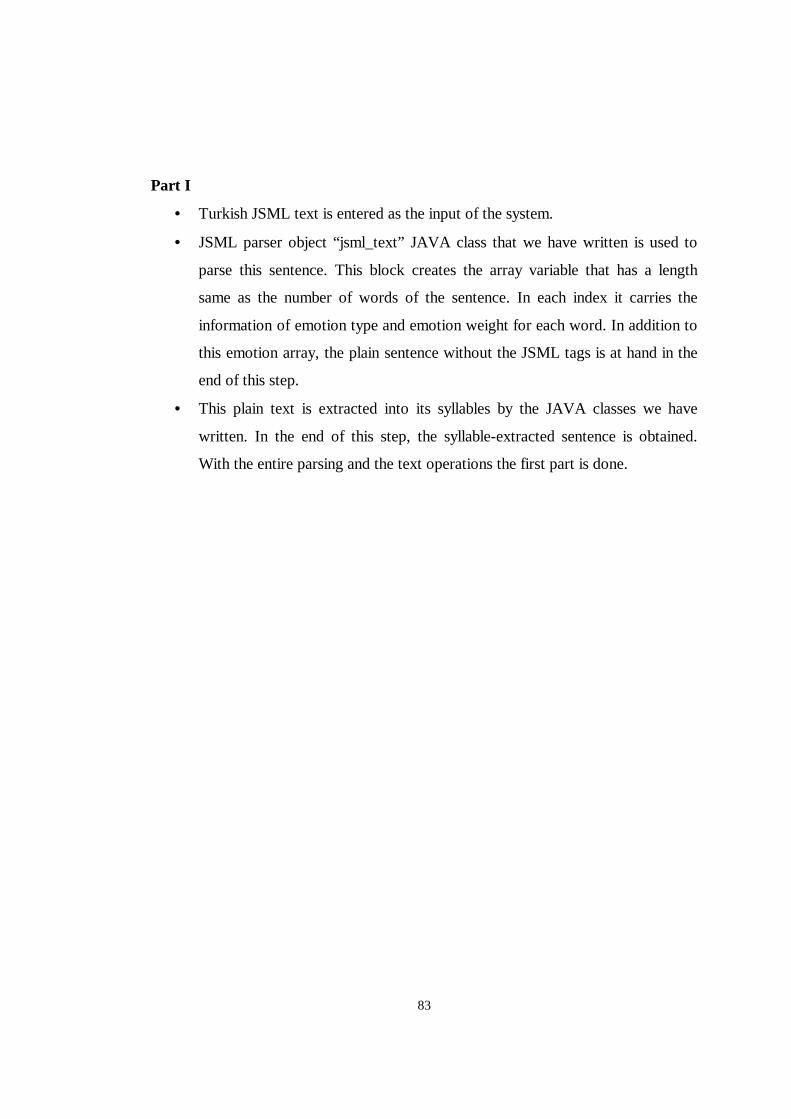
83
Part I
• Turkish JSML text is entered as the input of the system.
• JSML parser object “ jsml_text” JAVA class that we have written is used to
parse this sentence. This block creates the array variable that has a length
same as the number of words of the sentence. In each index it carries the
information of emotion type and emotion weight for each word. In addition to
this emotion array, the plain sentence without the JSML tags is at hand in the
end of this step.
• This plain text is extracted into its syllables by the JAVA classes we have
written. In the end of this step, the syllable-extracted sentence is obtained.
With the entire parsing and the text operations the first part is done.
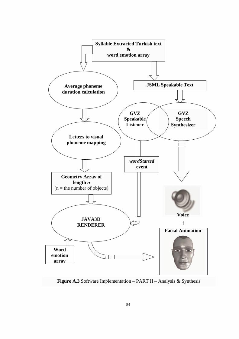
84
Average phoneme duration calculation
GVZ Speech
Synthesizer
GVZ Speakable L istener
+Voice
Facial Animation
wordStarted event
Word emotion ar ray
Syllable Extracted Turkish text &
word emotion ar ray
JSML Speakable Text
Geometry Ar ray of length n
(n = the number of objects)
Letters to visual phoneme mapping
JAVA3D RENDERER
Figure A.3 Software Implementation – PART II – Analysis & Synthesis
85
Part I I
• The inputs of the second part are syllable-extracted Turkish text and the
emotion array.
• The plain text of the previous step is sent to the GVZ speech engine as a
speakable text to be synthesized.
• At the same time the syllable extracted text is used to calculate the average
phoneme durations inside each word. As the system is word-by-word
synchronization based the phoneme duration inside the words are calculated
using a look-up table. After this step the phoneme duration array is ready.
• As the information of the information of each vowel inside the syllables the
words are mapped to their related 3D visual phonemes. According to the flow
of the sentence, a geometry array in the length of the number of letters in the
sentence is created and ready to be morphed and rendered.
• In this step the rendering is done.
o GVZ speech engine starts playing the speech voice. Before each word
it sends the wordStarted event.
o Using the geometry array, the word emotion array, and the phoneme
durations array the scene is rendered in consistent with the formula
5.4. Before each word start the wordStarted event is awaited.
As the output, the voice and the animation of the Turkish speaker is
generated.
86
APPENDIX B
TURKISH VISUAL PHONEMES
In appendix B, the pictures of the visual phonemes defined in Table 5.1 are given.
Refer to Table 5.1 to understand the mapping between these visual phonemes and
Turkish letters. In our implementation we have used these models as the 3D visual
phonemes.
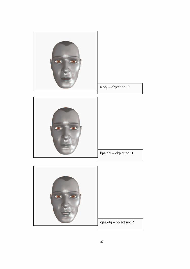
87
bpa.obj – object no: 1
a.obj – object no: 0
cjae.obj – object no: 2
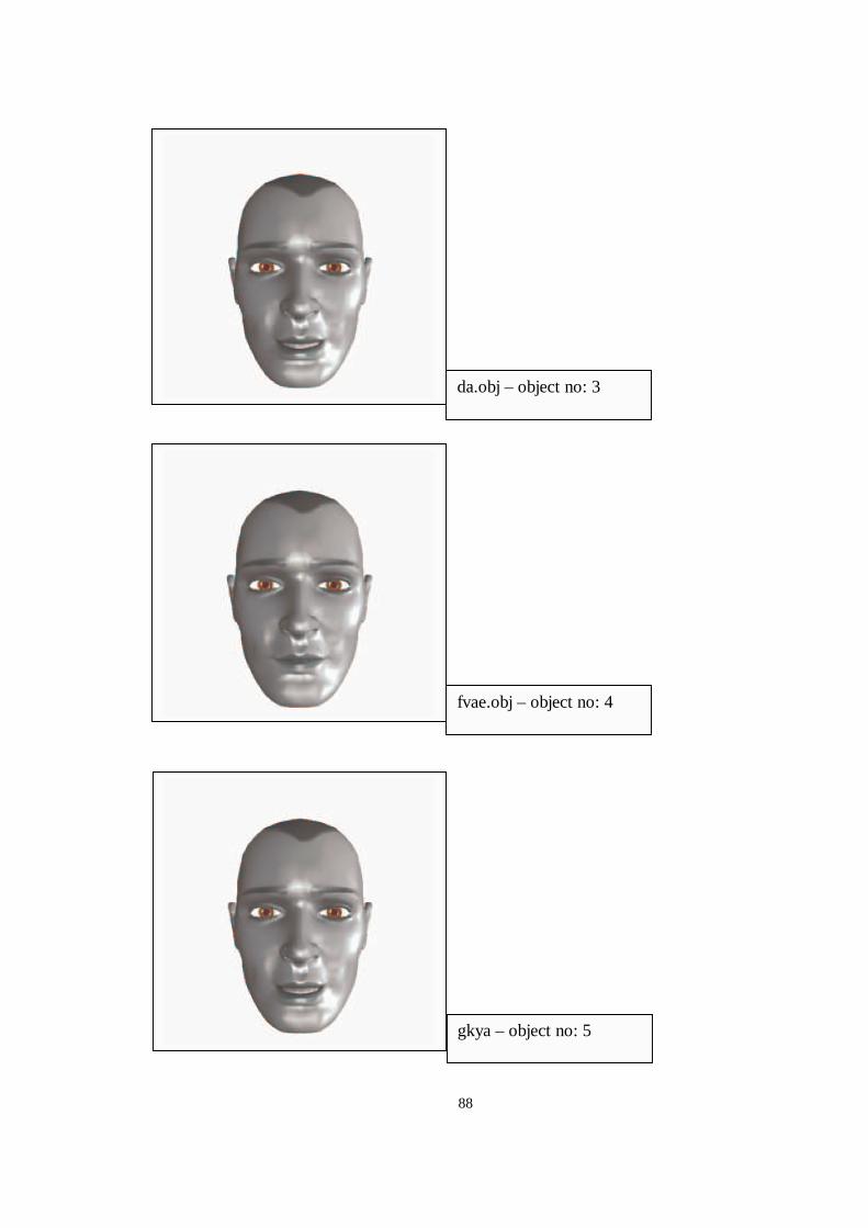
88
fvae.obj – object no: 4
da.obj – object no: 3
gkya – object no: 5
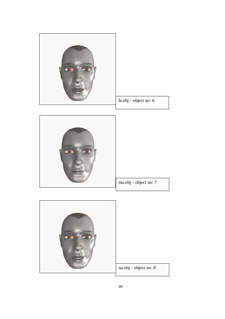
89
ma.obj – object no: 7
la.obj – object no: 6
na.obj – object no: 8
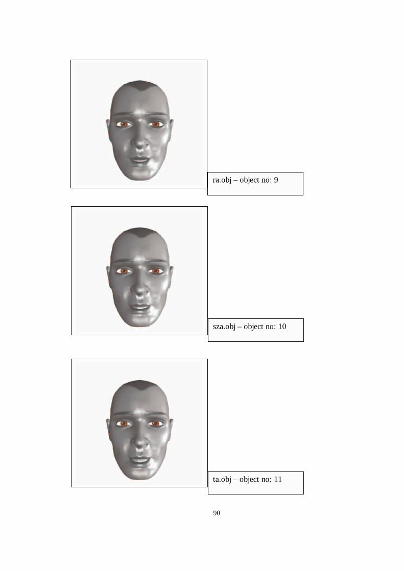
90
sza.obj – object no: 10
ra.obj – object no: 9
ta.obj – object no: 11
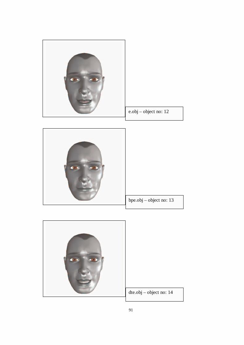
91
bpe.obj – object no: 13
e.obj – object no: 12
dte.obj – object no: 14
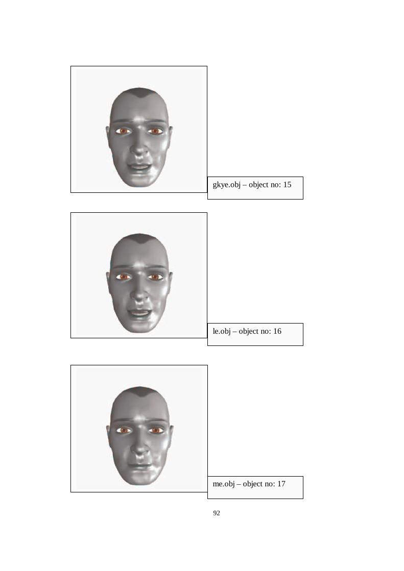
92
le.obj – object no: 16
gkye.obj – object no: 15
me.obj – object no: 17
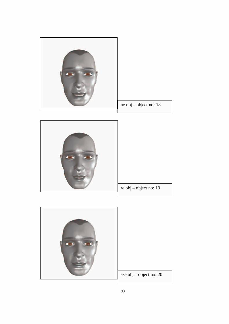
93
re.obj – object no: 19
ne.obj – object no: 18
sze.obj – object no: 20
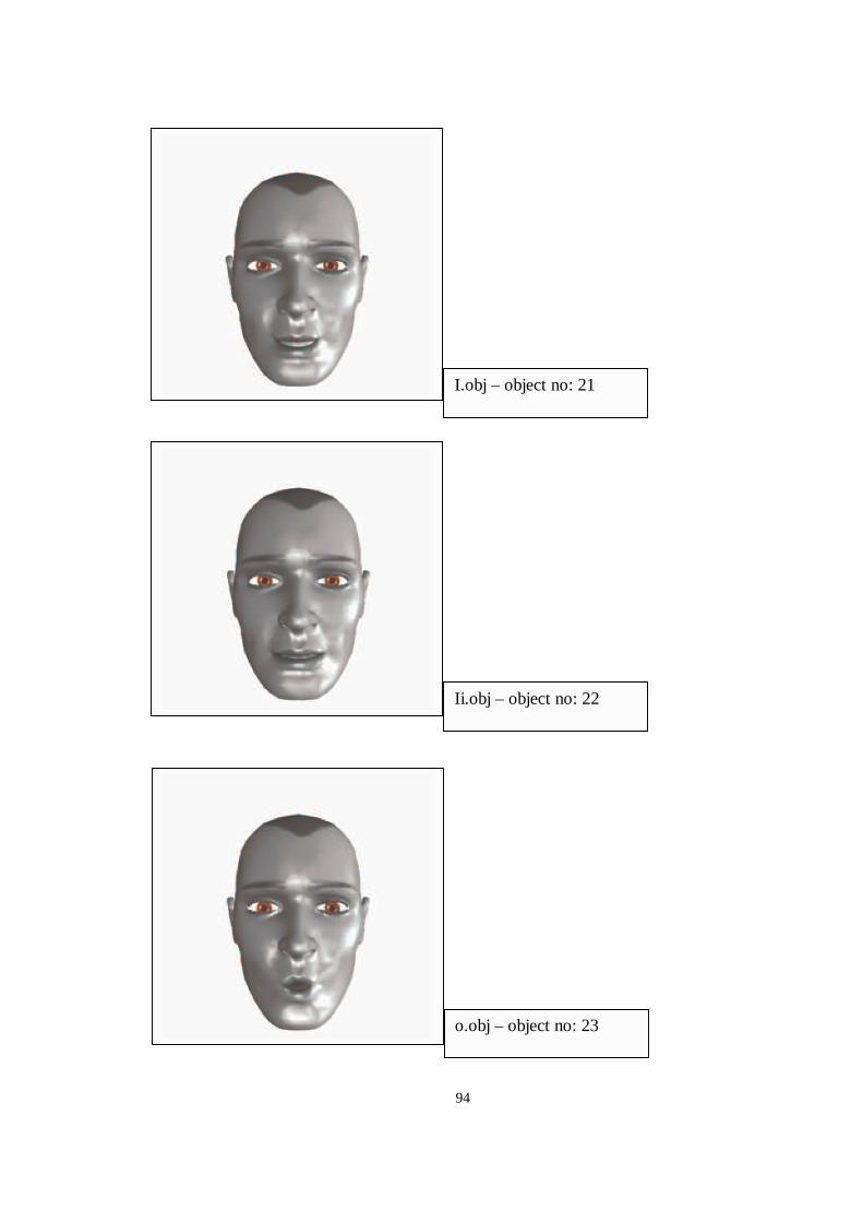
94
Ii.obj – object no: 22
I.obj – object no: 21
o.obj – object no: 23
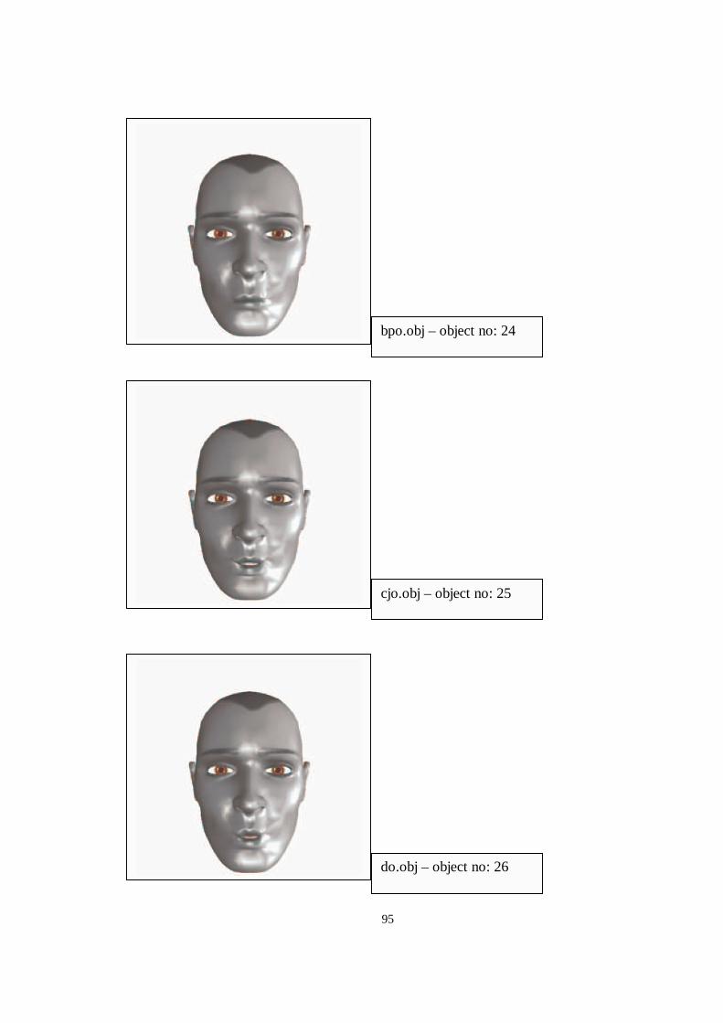
95
cjo.obj – object no: 25
bpo.obj – object no: 24
do.obj – object no: 26
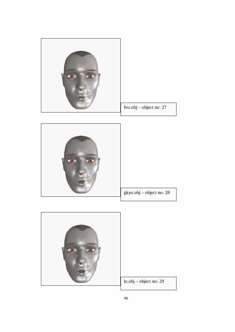
96
gkyo.obj – object no: 28
fvo.obj – object no: 27
lo.obj – object no: 29
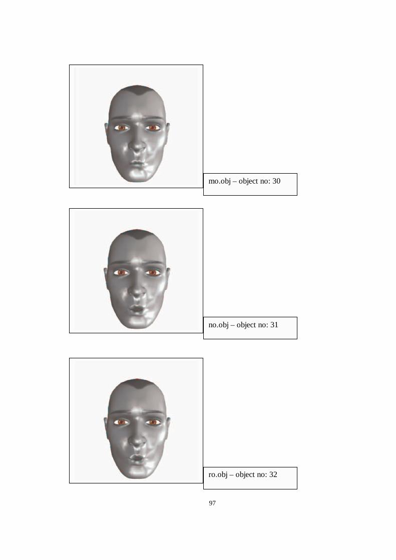
97
no.obj – object no: 31
mo.obj – object no: 30
ro.obj – object no: 32
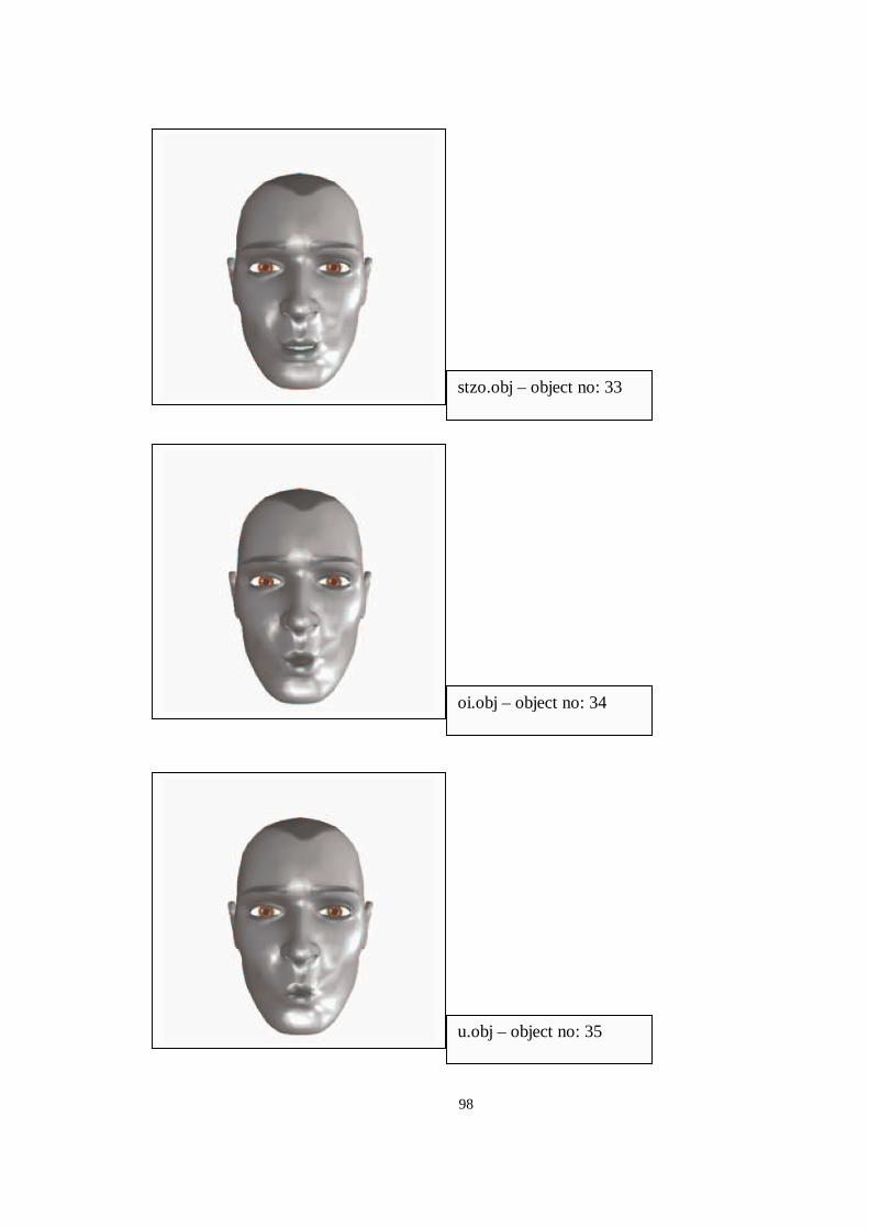
98
oi.obj – object no: 34
stzo.obj – object no: 33
u.obj – object no: 35
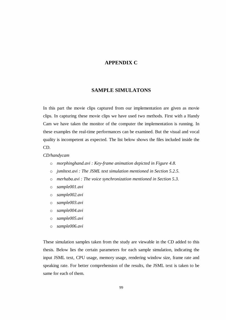
99
APPENDIX C
SAMPLE SIMULATONS
In this part the movie clips captured from our implementation are given as movie
clips. In capturing these movie clips we have used two methods. First with a Handy
Cam we have taken the monitor of the computer the implementation is running. In
these examples the real-time performances can be examined. But the visual and vocal
quality is incompetent as expected. The list below shows the files included inside the
CD.
CD/handycam
o morphinghand.avi : Key-frame animation depicted in Figure 4.8.
o jsmltext.avi : The JSML text simulation mentioned in Section 5.2.5.
o merhaba.avi : The voice synchronization mentioned in Section 5.3.
o sample001.avi
o sample002.avi
o sample003.avi
o sample004.avi
o sample005.avi
o sample006.avi
These simulation samples taken from the study are viewable in the CD added to this
thesis. Below lies the certain parameters for each sample simulation, indicating the
input JSML text, CPU usage, memory usage, rendering window size, frame rate and
speaking rate. For better comprehension of the results, the JSML text is taken to be
same for each of them.
100
JSML text input :
<SENT><SURPRISED>merhaba</SURPRISED>, benim adım
erdem</SENT>
filename
Speaking rate
(word/min) Window size
(x,y)
CPU usage
(%)
Memory usage (MB)
Frame rate (fps)
sample001.avi 75 390,397 100 267 46.28
sample002.avi 100 390,397 100 267 45.81
sample003.avi 150 390,397 100 267 43.56
sample004.avi 75 190,197 100 267 48.97
sample005.avi 100 190,197 100 267 48.82
sample006.avi 150 190,197 100 267 46.33


![GeoModeler: Tightly linking spatially-explicit …dusk.geo.orst.edu/ACM_GIS_final.pdfThe GeoModeler application employs the Java3D API [27], which is designed as a high-level, platform](https://img.pdfslide.us/doc/110x75/5ad0b69b7f8b9a1d328e9dd2/geomodeler-tightly-linking-spatially-explicit-duskgeoorsteduacmgisfinalpdfthe.jpg)