Embed Size (px)
Citation preview

SIMULATION OF SPEED CONTROL BRUSHLESS DC MOTOR USING
GAUSSIAN FUZZY LOGIC CONTROLLER
NURLIANA BINTI ABD KARIM
A project report submitted in partial
fulfillment of the requirement for the award of the
Master of Electrical Engineering
Faculty of Electrical and Electronic Engineering
Universiti Tun Hussein Onn Malaysia
JANUARY, 2014

vi
ABSTRAK
Laporan projek ini membentangkan satu skim kawalan Fuzzy Logic bagi
pemacu motor tanpa berus arus terus. Motor arus terus tanpa berus ini mempunyai
beberapa kelebihan berbanding jenis motor lain. Walaubagaimanapun, pemacu motor
tanpa berus arus terus ini mempunyai ciri tidak linear menyebabkan ianya sukar
dikendali dengan menggunakan kawalan konventional seperti Proportional-integral-
differential Controller (PID). Oleh itu, untuk mengatasi masalah ini, kawalan Fuzzy
Logic dengan fungsi keahlian Gaussian dibangunkan. Model matematik untuk
pemacu motor arus terus tanpa motor diterbitkan. Pengawal ini direka untuk trek
variasi rujukan kelajuan dan menstabilkan kelajuan keluaran semasa variasi beban.
Keberkesanan kaedah yang dicadangkan disahkan dengan membangunkan model
simulasi dalam perisian Matlab Simulink. Keputusan simulasi menunjukkan
pengawal yang dicadangkan menghasilkan prestasi kawalan peningkatan yang ketara
berbanding dengan pengawal PID bagi kedua-dua keadaan mengawal rujukan
kelajuan perubahan dan variasi beban gangguan.

v
ABSTRACT
This paper presents a control scheme of a Fuzzy Logic for the brushless direct
current (BLDC) motor drives. The BLDC motor has some advantages compare to
others type of motors. However, the nonlinearity of this motor drive characteristics
cause it is difficult to handle using conventional proportional-integral-differential
(PID) controller. In order to overcome this main problem, Fuzzy Logic controller
with a Gaussian membership function is developed. The mathematical model of
BLDC motor is derived. The controller is designed to tracks variations of speed
references and stabilizes the output speed during load variations. The effectiveness
of the proposed method is verified by develop simulation model in Matlab Simulink
software. The simulation results show that the proposed Fuzzy Logic controller (FLC)
produce significant improvement control performance compare to the PID controller for
both condition controlling speed reference variations and load disturbance variations.

vii
CONTENTS
TITLE i
DECLARATION ii
DEDICATION iii
ACKNOWLEDGEMENT iv
ABSTRACT v
CONTENTS vii
LIST OF TABLES x
LIST OF FIGURES xi
LIST OF SYMBOLS AND ABBREVIATIONS xiii
LIST OF APPENDICES xv

viii
CHAPTER 1 INTRODUCTION 1
1.1 Project Overview 1
1.2 Problem Statements 2
1.3 Project Objectives 2
1.4 Project Scopes 3
CHAPTER 2 LITERATURE REVIEW 4
2.1 Introduction 4
2.2 Previous Case Study 4
2.3 Brushless Direct Current Motor 6
2.3.1 Construction and Operating Principle 7
2.3.1.1 Stator 7
2.3.1.2 Rotor 8
2.3.1.3 Hall Sensor 9
2.3.1.4 Theory of Operation 10
2.3.2 Torque/Speed Characteristics 10
2.3.3 Commutation Sequence 11
2.3.4 Back EMF 12
2.4 Fuzzy Logic Controller System 13
2.4.1 Fuzzification 14
2.4.2 Rule Base 16
2.4.3 Inference Engine 16
2.4.4 Deffuzzification 17
CHAPTER 3 METHODOLOGY 19
3.1 Introduction 19
3.2 System Structure 20
3.2.1 Structure of BLDC motor 20
3.2.2 Modelling of BLDC motor 22
3.2.3 Modelling of a Trapezoidal Back EMF
of BLDC motor 23

ix
3.2.4 Voltage Source Inverter (VSI) 25
3.2.5 Reference Current Generator 27
3.3 Proposed Controller 29
3.4 Fuzzy Logic Controller Design 29
3.4.1 Inference Mechanism 30
3.4.2 Defuzzifier 31
CHAPTER 4 RESULTS AND ANALYSIS 32
CHAPTER 5 CONCLUSIONS AND FUTURE WORK 47
5.1 Conclusions 47
5.2 Future Works 48
REFERENCES 49
APPENDICES 51

x
LIST OF TABLES
3.1 Reference currents of BLDC motor 28
3.2 Rule Base 31
4.1 Parameter of BLDC motor 33

xiii
LIST OF SYMBOL AND ABBREVIATIONS
B - Friction Coefficient
BLDC - Brushless Direct Current
DC - Direct Current
DSP - Digital Signal Processing
ea, e
b, e
c - The Phase Back-EMF
e ab
, ebc,
eca
- Line-to-line Back-EMF
e ia,
eib
, eic
- Error Phase Current
EMF - Electromagnetic Field
FLC - Fuzzy Logic Controller
fabc
(θr) - Function of rotor position
i a, i
b, ic - Stator Phase Current
ia ref, i
b ref, i
cref - Reference Phase Current
I max
- Reference Current
J - Moment of Inertia
jth
- Numbers of Neuron
K e
- Back-EMF Constant
K t
- Torque Constant
L - Self-inductance
M - Mutual Inductance
N - North
PID - Proportional Integral Derivative
R - Phase Resistance
RPM - Round per Minute

xiv
S - South
T a, T
b, T
c - Phase Electromagnetic Torque
T e
- Electromagnetic Torque
T L
- Load Torque
TP - Peak Torque
TR - Rated Torque
Va, V
b, V
c - Phase Voltage
V dc
- DC Supply Voltage
V ao
, Vbo
, Vco
- Reference to Midpoint of DC Supply Voltage
ω m
- Rotor Speed in mechanical
ω r
- Rotor Speed in electrical
Y - Star connection
- Delta connection
θ r
- Rotor Position

xi
LIST OF FIGURES
2.1 The stator of BLDC motor 8
2.2 Rotor magnet cross section 9
2.3 BLDC motor cross section 10
2.4 Torque speed characteristics 11
2.5 The hall sensor and trapezoidal back EMF waveforms of BLDC
motor drive 12
2.6 Triangular membership function shape 14
2.7 Trapezoidal membership function shape 15
2.8 Gaussian membership function shape 15
2.9 Generalized bell membership function shape 16
3.1 The block diagram of speed control using Gaussian fuzzy logic
controller for BLDC motor drive system. 19
3.2 Disassembled view of BLDC motor 20
3.3 The system for controlling the voltage and speed with the
associated current and voltage waveforms superimposed
on the circuits. 21
3.4 Trapezoidal back-EMF and phase current waveforms of
BLDC motor drive 23
3.5 Simulink diagram of generating back-EMF from rotor position 25
3.6 Simulink diagram of three-phase currents 27
3.7 Simulink diagram of reference currents block 28
3.8 Fuzzy logic for BLDC motor drive system 29
3.9 Structure of fuzzy logic controller 30

xii
4.1 Block diagram of the proposed Fuzzy Logic control for
BLDC motor 32
4.2 Rotor position waveform at speed 1500 rpm 34
4.3 Back-EMF waveform based on rotor position at speed 1500 rpm 34
4.4 Phase current waveform based on rotor position at speed 1500 rpm 35
4.5 Phase current reference waveform at speed 1500 rpm 35
4.6 Fuzzy controller response with Gaussian membership function
at load step change from 4 N-m to 2 N-m at t = 1s 36
4.7 Fuzzy controller response with triangular membership function
at load step change from 4 N-m to 2 N-m at t = 1s 37
4.8 Fuzzy controller response with trapezoidal membership
function at load step change from 4 N-m to 2 N-m at t = 1s 38
4.9 Fuzzy controller response with generalized bell membership
function at load step change from 4 N-m to 2 N-m at t = 1s 39
4.10 Speed performance of the PID controller for step up speed
reference 40
4.11 Speed performance of the FLC for step up speed reference 40
4.12 Speed performance of the PID controller for step up speed
reference 41
4.13 Speed performance of the FLC for step up speed reference 41
4.14 Speed performance of the PID controller for step
down speed reference 42
4.15 Speed performance of the FLC for step down speed reference 43
4.16 Speed performance of the PID controller for step
down speed reference 43
4.17 Speed performance of the FLC for step down speed reference 44
4.18 Speed performance during step load disturbance using PID
controller at 1000 rpm 45
4.19 Speed performance during step load disturbance using FLC
at 1000 rpm 45
4.20 Speed performance during step load disturbance using PID
controller at 1500 rpm 46
4.21 Speed performance during step load disturbance using PID
controller at 1500 rpm 46
xv
LIST OF APPENDICES
A Gaussian Fuzzy Logic Programming 51
B iabc_ref Programming 55
C Emf_abc Programming 57
D ref_wave Programming 59
E v_abc Programming 61
F thetang_blk Programming 64

CHAPTER 1
INTRODUCTION
1.1 Project Overview
Nowadays, Brushless Direct Current (BLDC) motors are one of the motor types
rapidly gaining popularity [1]. As the name implies, their only drawback is that they
need a commutator and brushes which are subject to wear and require maintenance.
When the functions of commutator and brushes were implemented by solid-state
switches, maintenance-free motors were realized.
BLDC motors have many advantages over brushed DC motors and induction
motors which is better speed versus torque characteristics, high dynamic response,
high efficiency, long operating life, noiseless operation and higher speed ranges. In
addition, the ratio of torque delivered to the size of the motor is higher, making it
useful in applications where space and weight are critical factors [1].
The applications BLDC motor are widely used in many industries as growth
as the rapidly developments in power electronic technology, manufacturing
technology for high performance magnetic materials and modern control theory for
motor drives [2]. Modern intelligent motion applications demand accurate speed and
position control due to the favorable electrical and mechanical properties of BLDC
motor. Many machine and control method have been developed to improve the
performance of BLDC motor drives [3].
Based on previous studies in linear system model, controller parameters of
proportional integral derivative (PID) controller are easy to determine and resulting
good control performances. However, for nonlinear system model application such

2
as BLDC motor drive, control performance of the PID controller becomes poor and
difficult to determine the controller parameters. So that, Fuzzy Logic Control (FLC)
will be used in order to improve the control performance.
In this project, a complete simulation model with FLC method for BLDC
motor drive is proposed using Matlab/Simulink.
1.2 Problem Statements
Direct Current (DC) motor was chosen for the speed control applications due to the
control simplicity on the intrinsic decoupling between the flux and the torque. As the
name implies, there are physical limitations to speed and life time because of brush
wear. However, BLDC have been produced to overcome this problem. Since there
are no carbon brushes to wear out, a BLDC motor can provide significantly greater
life being now only limited by bearing wear. This advantage make BLDC motor
becomes popular in the industry but this motor is a non-linear system hence, need
more complex speed controller than the DC motor.
By this reason, the Gaussian Fuzzy Logic controller will be developed to
improve the performance of variable speed for BLDC motor since the system of this
motor is non-linear system.
1.3 Project Objectives
The objectives of this project are:
i. To derive simulation model of BLDC motor using Matlab Simulation.
ii. To improve speed performances of BLDC motor such as reduces
overshoot; reduce rise time and steady state error by using Fuzzy Logic
controller.

3
1.4 Project Scopes
The scopes of this project are to simulate BLDC motor using Matlab Simulink software and
develop the FLC that will be used to control the variable speed of the BLDC motor. The
scopes of proposed FLC is limited to Gaussian membership function. The other membership
function of FLC also will be develop to compare the effectiveness of the proposed
controller.

CHAPTER 2
LITERATURE REVIEW
2.1 Introduction
In order to design and construct Gaussian Fuzzy Logic controller for BLDC motor
speed, research in FLC need to be performed. This chapter would discuss the
previous study of FLC that has been developing through the year.
2.2 Previous Case Study
Many approaches for designing controller based on the brushless DC motor has been
proposed on the previous papers. The fuzzy speed controller was chosen by the
designer due to their property. Fuzzy logic provides a useful methodology to create a
practical solution for controlling complex system.
Siong T. C. et al. (2011) are proposed fuzzy logic controller for BLDC
permanent magnet drives. The results shows that the fuzzy logic controller system
provided a good dynamic performances in both simulation and experimental.
A novel digital control technique for brushless DC motor drives is to introduce a
novel concept for digital control of trapezoidal BLDC motor. Rodriguez et al. (2007)
found that the proposed digital controller is well suited for applications where speed
ripple is not of significant importance.

5
This rapid control prototyping approach to fuzzy speed control of BLDC motor
paper are study by Tuncay R. N. et al.. In this paper, fuzzy controller is successfully
controlling the motor and the model based programming of DSPs. Fuzzy logic
controller is founded more robust and fast than other conventional control
techniques. It is also very simple and versatile.
This research has proposed a speed controller with adaptive fuzzy tuning
method for the BLDC motor drives by Kwon C. J. et al. (2003). The simulation
results have confirmed the good speed response and the efficiency of the proposed
adaptive fuzzy logic scheme for changing motor parameter and load torque.
In this paper, a speed control for the BLDC motor based on a combination
between sliding mode control and fuzzy logic is presented by Rusu C. The results of
simulation and experiment show that the performance of the system drive has some
advantages than using a pure siding mode control. The control precision of the
system by using fuzzy sliding mode control is improved.
Cunkas M. et al. (2010) proposed realization of fuzzy logic controlled BLDC
motor drives using matlab/simulink. In this study, it is seen that the desired real
speed and torque values could be reached in a short time by fuzzy logic controller.
The results show that MATLAB paired with simulink is a good simulation tool for
modeling and analyze fuzzy logic controlled brushless DC motor drives.
In addition, Parhizkar N. et al. (2011) have presented direct torque control of
BLDC motor drives with reduced starting current using fuzzy logic controller. Direct
torque control offers some advantages such as simple algorithm, simplicity to
implement, faster torque response, reduced torque ripple and less sensitivity to
parameters variations. Fuzzy logic controller is used in order to eliminate overshoot
exists in speed and torque responses. In addition by using fuzzy logic controller,
starting current reduced due to reliability of this controller.
Brushless DC Motor Speed Control System Based on Fuzzy Neural Network
Control has been proposed by Lv Y. et al. (2009). This paper presented fuzzy-neural
network controller, which is based on Gaussian function, was successfully
implemented herein in this study to achieve the control of the speed of the BLDCM.
The simulation results show that the controller of the proposed method has a good
adaptability and strong robustness when the system is disturbed, which is better than
traditional PID control.

6
Oyedepo J. A. et al. (2011) have proposed Implementation of a fuzzy logic
speed controller for a permanent magnet BLDC motor drive system. In this paper,
the characteristics of permanent brushless DC motor, its steady state operation and its
various torque-speeds/torque-current characteristics are studied. The speed of a
BLDC Motor has been successfully controlled by using fuzzy logic controller
technique. A comprehensive analysis of BLDC drive system has been performed by
using fuzzy logic controller.
Chen W. et al. (2006) have presented sensorless control of BLDC motor
based on fuzzy logic. The result shows that fuzzy logic controller can reduce the
torque ripple. There is also has no neutral voltage, phase shifted or silent phase are
required in this method which ensure its accuracy and stability.
Based on the previous case study, the researchers make a great effort to
propose the good controller to control the speed of BLDC motor. Although the
method is differ from each other, it is still can be conclude that fuzzy logic controller
is the better controller compared to other conventional controller. Therefore, in this
paper will use the fuzzy logic control as the controller of BLDC motor speed.
2.3 Brushless Direct Current Motor
The Brushless Direct Current (BLDC) motor is the ideal choice for applications that
require high reliability, high efficiency, and high power-to-volume ratio. Generally
speaking, a BLDC motor is considered to be a high performance motor that is
capable of providing large amounts of torque over a vast speed range. BLDC motors
are a derivative of the most commonly used DC motor, the brushed DC motor, and
they share the same torque and speed performance curve characteristics.
The major difference between the two is the use of brushes. BLDC motors
do not have brushes and must be electronically commutated. Commutation is the act
of changing the motor phase currents at the appropriate times to produce rotational
torque. In a brush DC motor, the motor assembly contains a physical commutator
which is moved by means of actual brushes in order to move the rotor. With a
BLDC motor, electrical current powers a permanent magnet that causes the motor to

7
move, so no physical commutator is necessary. A BLDC motor is highly reliable
since it does not have any brushes to wear out and replace.
2.3.1 Construction and Operating Principle
BLDC motors are a type of synchronous motor. This means the magnetic field
generated by the stator and rotor rotate at the same frequency. BLDC motor does not
operate directly off a DC voltage source. It consists of a rotor with permanent
magnets, a stator with windings and commutation that is performed electronically.
Normally three Hall sensors are used to detect the rotor position and commutation is
performed based on Hall sensor inputs. There are two types of stator windings
variants which are trapezoidal and sinusoidal motors.
2.3.1.1 Stator
The stator of a BLDC motor consists of stacked steel laminations with windings
placed in the slots that are axially cut along the inner periphery as in Figure 2.1.
Windings in a stator can be arranged in two patterns which is a star pattern (Y) or
delta pattern (∆). Most BLDC motors have three stator windings connected in star
connection. The winding formed when each of these winding are constructed with
numerous coils interconnected together. The stator windings construct into two types
which is trapezoidal and sinusoidal motors.

8
Figure 2.1: The stator of BLDC motor [13]
2.3.1.2 Rotor
The rotor of a typical BLDC motor is made out of permanent magnets. Depending
upon the application requirements, the number of poles in the rotor may vary.
Increasing the number of poles does give better torque but at the cost of reducing the
maximum possible speed. Another rotor parameter that impacts the maximum
torque is the material used for the construction of permanent magnet; the higher the
flux density of the material, the higher the torque. Figure 2.2 shows cross sections of
different arrangements of magnets in a rotor.

9
N
S
N N
S S
S
S
S
N N
N
N
S N
S
Circular core with magnets Circular core with rectangular Circular core with rectangular
on the periphery magnets embedded in the rotor magnets inserted into the rotor core
Figure 2.2: Rotor Magnet Cross Section
2.3.1.3 Hall Sensor
Hall sensors work on the hall-effect principle that when a current-carrying conductor
is exposed to the magnetic field, charge carriers experience a force based on the
voltage developed across the two sides of the conductor. If the direction of the
magnetic field is reversed, the voltage developed will reverse as well. For Hall-effect
sensors used in BLDC motors, whenever rotor magnetic poles North (N) or South (S)
pass near the hall sensor, they generate a HIGH or LOW level signal, which can be
used to determine the position of the shaft. Most BLDC motor consists of three Hall
Effect sensors and the combination of this sensor will produce the exact
sequence of commutation. Figure 2.3 represents a cross section of a BLDC motor
with rotor that has alternate North and South permanent magnets. There are two
output versions by referring the physical position of the Hall sensors either at 60˚ or
120˚ phase shift to each other.

10
Figure 2.3: BLDC motor cross section [2]
2.3.1.4 Theory of Operation
Three windings on each commutation have different function. First windings will
energized to positive power (current inflow into the winding), the second winding for
negative (current out flow the winding) and the last winding is in a non-energized
condition. The interaction between the permanent magnet and magnetic field
generated by the stator coils will produce the torque. Basically, the peak torque
occurs when these two fields are at 90˚ to each other and falls off as the field move
together. In order to keep the motor running, the magnetic field produced by the
winding should shift position as the rotor moves to catch up with the stator field.
2.3.2 Torque/Speed Characteristics
Based on the Figure 2.4, the BLDC motor can define using two torque parameters, a
peak torque (TP) and rated torque (TR). The motor can be loaded up to the rated
torque during continuous operations. The torque remains constant in a BLDC motor
for speed range up to the rated speed. Meanwhile it capable to run up to the
maximum speed which is 150% of the rated speed but the torque starts dropping
during this situation.

11
Peak
Torque
Maximum
Speed Rated Speed
Rated
Torque
Speed
Torque
Intermittent
Torque
Continuous
Torque Zone
Figure 2.4: Torque/Speed Characteristic
2.3.3 Commutation Sequence
Every 60 electrical degrees of rotation, one of the Hall sensors changes the state.
Given this, it takes six steps to complete an electrical cycle. In synchronous, with
every 60 electrical degrees, the phase current switching should be updated.
However, one electrical cycle may not correspond to a complete mechanical
revolution of the rotor. The number of electrical cycles to be repeated to complete a
mechanical rotation is determined by the rotor pole pairs. For each rotor pole pairs,
one electrical cycle is completed. So, the number of electrical cycles equals the rotor
pole pairs. Figure 2.5 shows the Hall sensors signals with respect to back EMF and
the phase current.

12
(1) (2) (3) (4) (5) (6) (1) (2) (3) (4) (5) (6)
Figure 2.5: The hall sensor and trapezoidal back EMF waveforms of BLDC motor
drive
2.3.4 Back EMF
According to Faradays law of electromagnetic induction, an EMF is induced or
produced in a conductor and if a closed path is provided, the current will flows
through it when a current carrying conductor is placed in a magnetic field. When the
same thing happens in a brushless DC motor (BLDC) as a result of motor torque, the
EMF produced is known as back EMF. It is so called because this EMF that is
induced in the motor opposes the EMF of the generator.
This back EMF that is induced in the brushless DC motor (BLDC) is directly
proportional to the speed of the armature (rotor) and field strength of the motor,
which means that if the speed of the motor or field strength is increased, the back
EMF will be increased and vice versa. When the DC motor is first started, there is
no back EMF induced and there is maximum current flow from the DC generator or
distribution lines to the motor armature and as a result the motor toque will be
maximum. During normal operation (rated speed) of DC motor, the back EMF
induced will be maximum which reduces the motor armature current to its minimum
180 360 540 720
A
B
C
A+ B- B+ C- C+ A-
Hall
sensor
output
Back
EMF

13
level and as a result the motor torque is also reduced. When the load on the motor is
increased, the motor speed (RPM) is decreased and this reduces the back EMF. This
decrease in back EMF automatically increases the motor torque thereby bringing the
motor to its rated speed.
2.4 Fuzzy Logic Controller System
Fuzzy logic and fuzzy control theories added a new dimension to control systems
engineering in the early 1970s. From its beginnings as mostly heuristic, somewhat
ad-hoc, more recent and rigorous approaches to fuzzy control theory have helped
make it integral part of modem control theory and produced many exciting results.
Fuzzy logic is a technique to embody human like thinking which is much less rigid
than the calculations computer generally perform into a control system. Fuzzy
controller can be designed to emulate human deductive thinking, that is, the process
people use to infer conclusion from what they know. Meanwhile, conventional
controller requires formal modeling of the physical reality of any plant.
Apart from that, fuzzy control incorporates ambiguous human logic into
computer programs. It suit control problem that cannot be easily represented by
mathematical model. Design of such controller leads to faster development and
implementation cycles due to its unconventional approach.
There are four important elements in the fuzzy logic controller system
structure which are fuzzifier, rule base, inference engine and defuzzifier. Firstly, a
crisp set of input data are gathered and converted to a fuzzy set using fuzzy linguistic
variables, fuzzy linguistic terms and membership functions. This step also known as
fuzzification. Afterwards, an inference is made base on a set of rules. Lastlty, the
resulting fuzzy output is mapped to a crisp output using the membership functions, in
the defuzzification step.

14
2.4.1 Fuzzification
Fuzzification is a process of making a crisp quantity fuzzy. Before this process is
taken in action, the definition of the linguistic variables and terms is needed.
Linguistic variables are the input or output variables of the system whose values are
words or sentences from a natural language, instead of numerical values. A linguistic
variable is generally decomposed into asset of linguistic terms.
There are different forms or shapes of membership functions in Fuzzy Logic
such as triangular, Gaussian, trapezoidal and generalized bell. The most common
type of membership function used by many applications is triangular. The type of the
membership function can be context dependent and it is generally chosen arbitrarily
according to the user experience. Figure 2.6 to Figure 2.9 shows the different types
of membership function shape.
Figure 2.6: Triangular membership function shape
The equation of triangular membership can defined as follows;
𝑡𝑟𝑖𝑎𝑛𝑔𝑙𝑒 (𝑥; 𝑎, 𝑏, 𝑐) =
{
0, 𝑥 ≤ 𝑎
𝑥−𝑎
𝑏−𝑎, 𝑎 ≤ 𝑥 ≤ 𝑏
𝑐−𝑥
𝑐−𝑏, 𝑏 ≤ 𝑥 ≤ 𝑐
0, 𝑐 ≤ 𝑥
(2.1)

15
Figure 2.7: Trapezoidal membership function shape
The equation of trapezoidal membership can defined as follows;
𝑡𝑟𝑎𝑝𝑒𝑧𝑜𝑖𝑑 (𝑥; 𝑎, 𝑏, 𝑐) =
{
0, 𝑥 ≤ 𝑎
𝑥−𝑎
𝑏−𝑎, 𝑎 ≤ 𝑥 ≤ 𝑏
1, 𝑏 ≤ 𝑥 ≤ 𝑐𝑑−𝑥
𝑑−𝑐, 𝑐 ≤ 𝑥 ≤ 𝑑
0, 𝑑 ≤ 𝑥
(2.2)
Figure 2.8: Gaussian membership function shape
The equation of Gaussian membership can defined as follows;
𝑔𝑎𝑢𝑠𝑠𝑖𝑎𝑛 (𝑥; 𝑐, 𝜎) = {𝑒−1
2(𝑥−𝑐
𝜎)2
(2.3)

16
Figure 2.9: Generalized bell membership function shape
The equation of generalized bell membership can defined as follows;
𝑏𝑒𝑙𝑙 (𝑥; 𝑎, 𝑏, 𝑐) = 1
1+|𝑥−𝑐
𝑎|2𝑏 (2.4)
2.4.2 Rule base
Fuzzy logic’s linguistic terms are most often expressed in the form of logical
implications, such as If-Then rules. These rules define a range of values known as
fuzzy membership functions. A rule base (a set of If-Then rules), which contains a
fuzzy logic quantification of the expert’s linguistic description of how to achieve
good control. Once the rules have been established, a fuzzy logic system can be
viewed as a mapping from inputs to outputs.
2.4.3 Inference engine
In general, inference is a process of obtaining new knowledge through existing
knowledge. In the context of fuzzy logic control system, it can be defined as a
process to obtain the final result of combination of the result of each rule in fuzzy
value.
There are many methods to perform fuzzy inference method and the most
common two of them are Mamdani and Takagi-Sugeno-Kang method. Mamdani

17
method was proposed by Ebrahim Mamdani as an attempt to control a steam engine
and boiler in 1975. It is based on Lofti Zadeh’s 1973 paper on fuzzy algorithms for
complex system and decision processes. This method uses the minimum operation Rc
as a fuzzy implication and the max-min operator for the composition. Suppose a rule
base is given in the following form;
IF input x = A AND input y = B THEN output z = C (2.5)
After the aggregation process, there is a fuzzy set for each output variable that needs
defuzzification. It is possible and in many cases much more efficient, to use a single
spike as the output membership functions rather than a distributed fuzzy set. This is
sometimes known as a singleton output membership function. It enhances the
efficiency of defuzzification process because it greatly simplifies the computation
required by the more general Mamdani method, which finds the centroid of two
dimensional function.
Meanwhile, Takagi-Sugeno-Kang method was introduced in 1985 and it is
similar to the Mamdani method in many aspects. The first two parts of fuzzy
inference process which are fuzzifying the inputs and applying the fuzzy operator are
exactly the same. But, the main difference is that the Takagi-Sugeno-Kang output
membership function is either linear or constant. A typical rule in Takagi-Sugeno-
Kang fuzzy model has the form as follows;
IF input 1 = x AND input 2 = y THEN output z = ax + by+ c (2.6)
2.4.4 Defuzzification
After the inference step, the overall result is a fuzzy value. This result should be
defuzzified to obtain a final crisp output. This is the purpose of the defuzzification
component of a fuzzy logic controller system. Defuzzification is performed
according to the membership function of the output variable.
There are many different methods for defuzzification such as Centroid of
Gravity (COG), Mean of Maximum (MOM), Weighted Average, Bisector of Area
(BOA), First of Maxima and Last of Maxima. There is no systematic procedure for

18
choosing a good defuzzification strategy, but the selection of defuzzification
procedure is depends on the properties of the application.
Centroid of Gravity (COG) is the most frequent used and the most prevalent
and physically appealing of all defuzzification methods. The basic equation of
Centroid of Gravity (COG) as below;
𝑢0 = ∫ 𝜇𝑢 (𝑢)𝑢 𝑑𝑢𝑢
∫ 𝜇𝑢 (𝑢)𝑑𝑢𝑢
(2.7)
Where uo is control output obtained by using Centroid of Gravity (COG)
defuzzification method.

CHAPTER 3
METHODOLOGY
3.1 Introduction
This chapter will divide into three phases. The first phase is understands the BLDC motor
drive. The second phase is implementing the basic concept of fuzzy logic controller. The
last phase is design and constructs the fuzzy logic controller for BLDC motor speed.
The proposed general block diagram for speed control of BLDC motor drive
system using Gaussian fuzzy logic controller is shown in Figure 3.1.
Figure 3.1: The block diagram of speed control using Gaussian fuzzy logic controller for
BLDC motor drive system.
Reference
speed
Gaussian Fuzzy Logic
Controller
Brushless DC
Motor Output
20
3.2 System Structure
3.2.1 Structure of BLDC Motor
The speed and torque characteristics of Brushless DC (BLDC) motors are very similar to a
shunt wound "brushed" (field energized) DC motor with constant excitation. As with
brushed motors the rotating magnets passing the stator poles create a back EMF in the
stator windings. When the motor is fed with a three phase stepped waveform with positive
and negative going pulses of 120 degrees duration, the back EMF or flux wave will be
trapezoidal in shape.
BLDC motors are not strictly DC motors. It is use a pulsed DC fed to the stator
field windings to create a rotating magnetic field and operate at synchronous speed. In
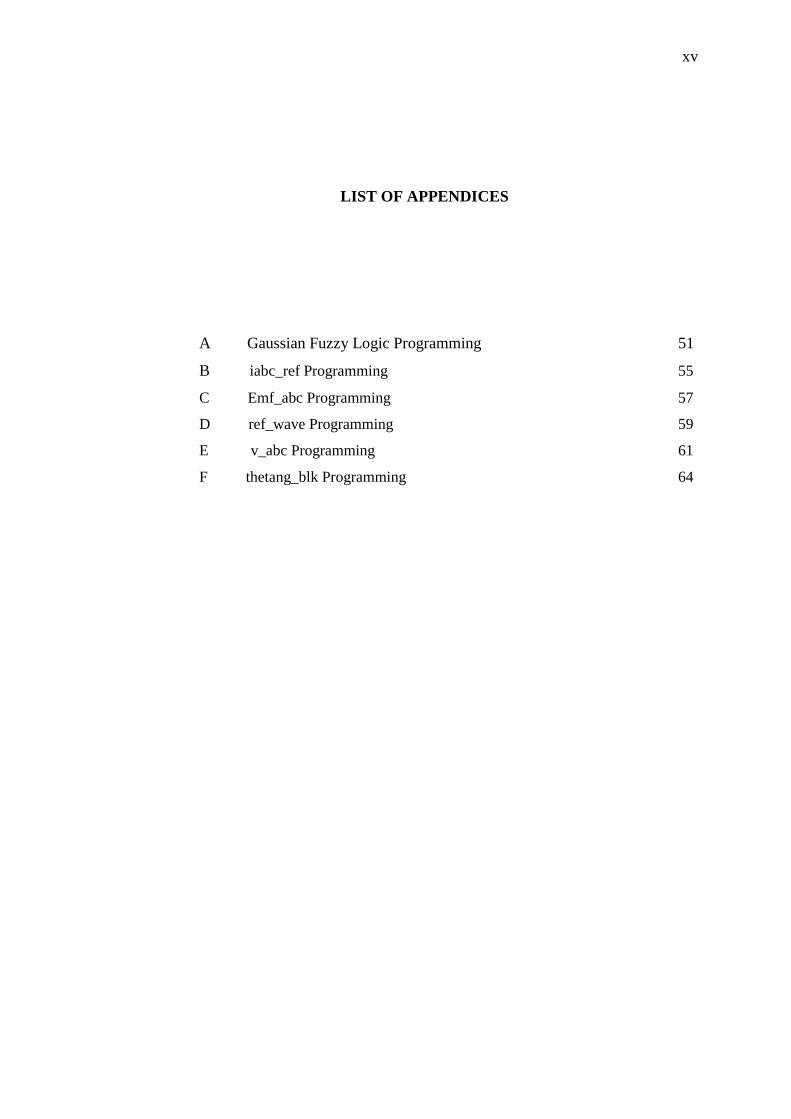
figure 3.2 shown that, pole pair A is first fed with a DC pulse which magnetizes pole A1 as
a South Pole and A2 as a North Pole drawing the magnet into its initial position. As the
magnet passes the first magnetized pole pair, the current to pole pair A is switched off and
the next pole pair B is fed with a similar DC pulse as pole pair A. The magnet will then
rotate clockwise to align itself with pole pair B. By pulsing the stator pole pairs in
sequence the magnet will continue to rotate clockwise to keep itself aligned with the
energized pole pair.
Figure 3.2: Disassembled view of BLDC motor. [14]

21
A six step inverter is used to generate the three phase supply and the electronic
commutation between the three pairs of stator coils needed to provide the rotating field.
Only two out of three pole pairs are energized at any one time. The speed of rotation is
controlled by the pulse frequency and the torque by the pulse current.
The inverter current pulses are triggered in a closed loop system by a signal which
represents the instantaneous angular position of the rotor. The frequency of the power
supply is thus controlled by the motor speed. Rotor position can be determined by a Hall
Effect device, embedded in the stator, which provide an electrical signal representing the
magnetic field strength. The amplitude of this signal changes as the magnetic rotor poles
pass over the sensor. Figure 3.3 shows the system for controlling the voltage and speed
with the associated current and voltage waveforms superimposed on the circuits.
Figure 3.3: The system for controlling the voltage and speed with the associated
current and voltage waveforms superimposed on the circuits. [14]
3ф VSI
system

22
3.2.2 Modelling of a BLDC motor
The analysis of BLDC motor is based on the assumption for simplification and accuracy.
The BLDC motor is type of unsaturated. The stator resistances for all the winding are equal
and the self and mutual inductance are constant. Semiconductor devices of inverter are
ideal and iron losses are negligible. Meanwhile, the back-EMF wave-forms of all phases
are equal. Based on the equivalent circuit of BLDC motor and VSI system shown in Figure
3.3, the dynamic equations of BLDC motor using the assumption can be derived as
𝑉𝑎 = 𝑅𝐼𝑎 + (𝐿 − 𝑀)𝑑𝑖𝑎
𝑑𝑡+ 𝑒𝑎 (3.1)
𝑉𝑏 = 𝑅𝐼𝑏 + (𝐿 − 𝑀)𝑑𝑖𝑏
𝑑𝑡+ 𝑒𝑏 (3.2)
𝑉𝑐 = 𝑅𝐼𝑐 + (𝐿 − 𝑀)𝑑𝑖𝑐
𝑑𝑡+ 𝑒𝑐 (3.3)
Where
Va, Vb, Vc = Stator phase voltages
ia, ib, ic = Stator phase current
ea, eb, ec =Phase back EMF
L = Self inductance
M = Mutual inductance
R = Phase resistance
The motion equation is defined as :-
𝑑𝜔𝑚
𝑑𝑡= (
𝑃
2𝐽) (𝑇𝑒 − 𝑇𝐿 − 𝐵𝜔𝑟) (3.4)
𝑑𝜃
𝑑𝑡= 𝜔𝑟 (3.5)
Where
Te = The electromagnetic torque
TL = Load torque (Nm)
J = Moment of inertia (kgm2)

23
B = Friction coefficient (Nms/rad)
m = Rotor speed in mechanical (rad/s)
r = Rotor speed in electrical (rad/s)
3.2.3 Modelling of a Trapezoidal Back EMF of BLDC motor
The trapezoidal back-EMF wave forms are modeled as a function of rotor position so that
rotor position can be actively calculated according to the operation speed. The back EMFs
are expressed as a function of rotor position (θr).
𝑒𝑎𝑏𝑐 = 𝑓𝑎𝑏𝑐(𝜃𝑟 ) × 𝐸 (3.6)
𝐸 = 𝑘𝑒𝜔𝑟 (3.7)
Where (𝑘𝑒) is back-EMF constant, 𝑓𝑎𝑏𝑐(𝜃𝑟 ) are the function of rotor position.
Figure 3.4: Trapezoidal back-EMF and phase current waveforms of BLDC motor
drive

24
Figure 3.4 represent the back-EMF is a function of rotor position and has the amplitude.
Based on the rotor position, the expression of the back-EMF can be generated as equation
(3.8), (3.9) and (3.10) where named as trapezoidal shape functions with limit values
between +1 and -1
𝑓𝑎(𝜃𝑟) =
[ (
6
) 𝜃𝑟 (0 < 𝜃𝑟 ≤
𝜋
6)
1 (𝜋
6< 𝜃𝑟 ≤ 5
𝜋
6)
−(6
) 𝜃𝑟 + 6 (5
𝜋
6< 𝜃𝑟 ≤ 7
𝜋
6)
−1 (7𝜋
6< 𝜃𝑟 ≤ 11
𝜋
6)
(6
) 𝜃𝑟 − 12 (11
𝜋
6< 𝜃𝑟 ≤ 2𝜋) ]
(3.8)
𝑓𝑏(𝜃𝑟) =
[ −1 (0 < 𝜃𝑟 ≤
𝜋
6)
(6
) 𝜃𝑟 − 4 (
𝜋
6< 𝜃𝑟 ≤ 5
𝜋
6)
1 (5𝜋
6< 𝜃𝑟 ≤ 7
𝜋
6)
− (6
) 𝜃𝑟 + 10 (7
𝜋
6< 𝜃𝑟 ≤ 11
𝜋
6)
−1 (11𝜋
6< 𝜃𝑟 ≤ 2𝜋)]
(3.9)
𝑓𝑐(𝜃𝑟) =
[ 1 (0 < 𝜃𝑟 ≤
𝜋
6)
− (6
) 𝜃𝑟 + 2 (
𝜋
6< 𝜃𝑟 ≤ 5
𝜋
6)
−1 (5𝜋
6< 𝜃𝑟 ≤ 7
𝜋
6)
(6
) 𝜃𝑟 − 8 (7
𝜋
6< 𝜃𝑟 ≤ 11
𝜋
6)
1 (11𝜋
6< 𝜃𝑟 ≤ 2𝜋) ]
(3.10)
The electromagnetic torque is defined by using back-EMFs as follows
𝑇𝑎 =𝑒𝑎𝑖𝑎
𝜔𝑟 (3.11)
𝑇𝑏 =𝑒𝑏𝑖𝑏
𝜔𝑟 (3.12)
𝑇𝑐 =𝑒𝑐𝑖𝑐
𝜔𝑟 (3.13)

49
REFERENCES
[1] Padmaraja Yedamale, “Brushless DC (BLDC) Motor Fundamentals”, in
Microchip Technology Inc. AN885 Datasheet, 2003, pp. 1.
[2] Raja Siti Nur Adiimah binti Raja Aris, “Simulation of a Variables Speed
Brushless DC Motor using Neural Network Controller,” Universiti Tun
Hussein Onn Malaysia, 2011.
[3] T.C Siong, B.Ismail, S.F.Siraj and M.F Mohammed, “Fuzzy Logic Controller
for BLDC Permanent Magnet Motor Drives,” in International Journal of
Electrical & Computer Sciences IJECS-IJENS Vol:11 No.2, Universiti
Malaysia Perlis, Malaysia, 2011, pp. 13-18.
[4] Rodriguez F. and Emadi A., “A Novel Control Technique for Brushless DC
Motor Drives,” in IEEE Transaction on Industrial Electronics, Vol. 54, No. 5,
2007, pp. 2365-2373.
[5] Tuncay R. N., Erenay Z., Yilmaz M., and Ustun O., “Rapid Prototyping
Approach to Fuzzy Speed Control of Brushless DC Motor”, Istanbul
Technical University, pp. 1-5.
[6] Kwon C. J., Han W. Y., Kim S. J. and Lee C. G., “Speed Controller with
Adaptive Fuzzy Tuning for BLDC Motor Drive under Load Variations”,
SICE Annual Conference in Fukui, 2003, pp. 2696-2699.
[7] Rusu C., “Fuzzy Sliding Mode Control of the Brushless DC Motor”,
Technical University of Cluij, pp. 415-419.
50
[8] Parhizkar N., Shafiei M. and Kouhshahi M. B., “Direct Torque Control of
Brushless DC Motor Drives with Reduced Starting Current Using Fuzzy
Logic Controller”, International Conference on Uncertainty Reasoning and
Knowledge Engineering,2011, pp. 129-132.
[9] Sharmila B. and Devarajan N., “Neuro-Fuzzy Controller for Networked DC
Motor Control”, European Journal of Scientific Research, 2011, pp. 219-228.
[10] Lv Y., Fan H., Zou Q. and Wan J., “Brushless DC Motor Speed Control
System Based on Fuzzy Neural Network Control”, Proceedings of the 2009
International Workshop on Information Security and Application, 2009, pp.
173-176.
[11] R. Akkaya, A.A. Kulaksız, and O Aydogdu, “DSP implementation of a PV
system with GA-MLP-NN based MPPT controller supplying BLDC motor
drive”, Energy Conv. and Management 48, 210-218, 2007.
[12] A. Pooja and P. Arpita, “Brushless DC Motor Speed Control Using
Proportional-Integral and Fuzzy Controller”, IOSR Journal of Electrical and
Electronics Engineering (IOSR-JEEE),68-78,2013.
[13] Techzone (2013), Microcontroller Solution, Retrieved on March 3, 2012,
from http://www.digikey.com.
[14] Electropaedia (2005), Battery and Energy Technology, Retrieved on March
25, 2012, from http://www.mpoweruk.com