Embed Size (px)
Citation preview
Simulation of Roll Forming
Florian Kern
Thomas Neitzert
AUT UNIVERSITYAUT UNIVERSITYTE WANANGA ARONUI O TAMAKI MAKAU RAUTE WANANGA ARONUI O TAMAKI MAKAU RAU
Outline
• Introduction
• Roll forming
• New developments
• Simulation of U-channel
• Summary and future work
Roll Forming
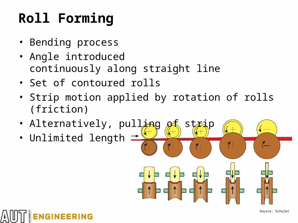
• Bending process• Angle introduced
continuously along straight line• Set of contoured rolls• Strip motion applied by rotation of rolls (friction)• Alternatively, pulling of strip• Unlimited length
Source: Schuler
Roll Forming - Boundaries
• Generally, materials that can be bent can also be roll formed
• Steel:– Thickness 0.1mm to 20mm– Width 3mm to 2m– Velocity 20m/min to 80m/min, some up to 160m/min– More demanding for higher yield strengths
• Product is prismatic
Typical Defects in Roll Forming
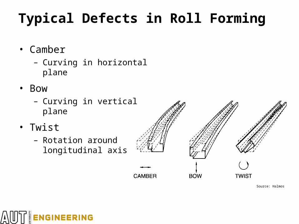
• Camber– Curving in horizontal plane
• Bow– Curving in vertical plane
• Twist– Rotation around
longitudinal axis
Source: Halmos
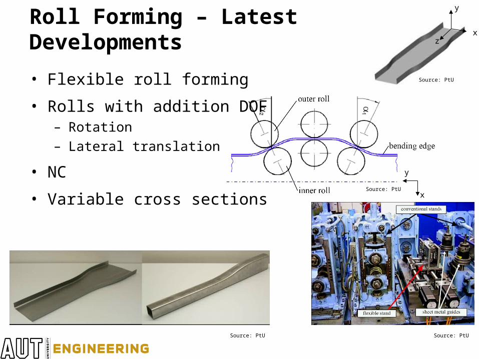
Roll Forming – Latest Developments
• Flexible roll forming
• Rolls with addition DOF– Rotation– Lateral translation
• NC
• Variable cross sections
Source: PtU Source: PtU
Source: PtU
Source: PtU
x
x
y
z
y
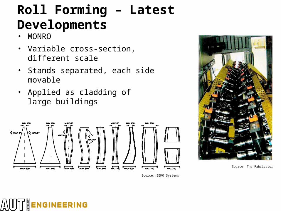
Roll Forming – Latest Developments• MONRO
• Variable cross-section, different scale
• Stands separated, each side movable
• Applied as cladding of large buildings
Source: BEMO Systems
Source: The Fabricator
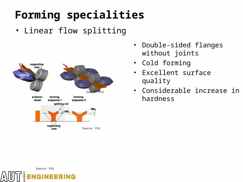
Forming specialities• Linear flow splitting
• Double-sided flanges without joints
• Cold forming• Excellent surface quality• Considerable increase in
hardnessSource: PtU
Source: PtU
Source: PtU
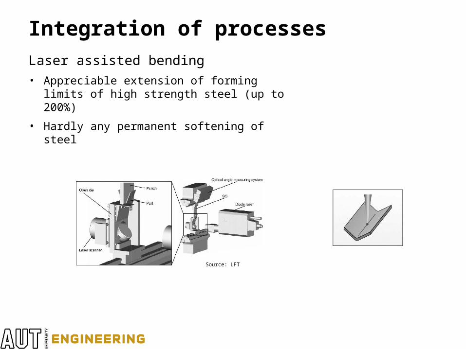
Integration of processes
Laser assisted bending
• Appreciable extension of forming limits of high strength steel (up to 200%)
• Hardly any permanent softening of steel
Source: LFT
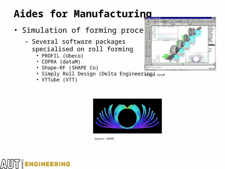
Aides for Manufacturing
• Simulation of forming process
– Several software packagesspecialised on roll forming
• PROFIL (Ubeco)• COPRA (dataM)• Shape-RF (SHAPE Co)• Simply Roll Design (Delta Engineering)• VTTube (VTT)
Source: SHAPE
Source: dataM
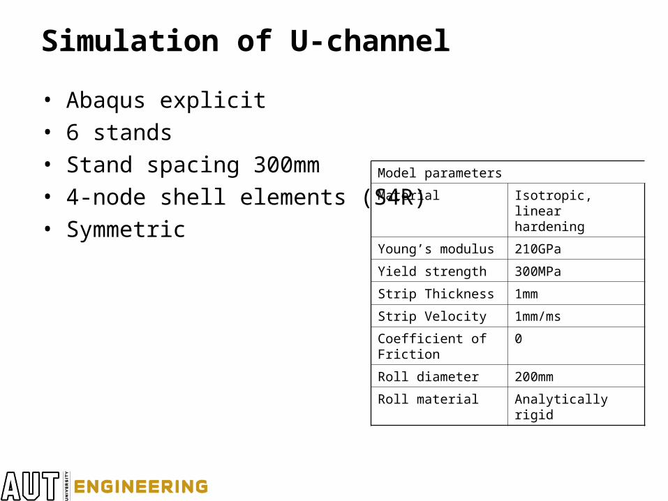
Simulation of U-channel
• Abaqus explicit• 6 stands• Stand spacing 300mm• 4-node shell elements (S4R)• Symmetric
Model parameters
Material Isotropic, linear hardening
Young’s modulus 210GPa
Yield strength 300MPa
Strip Thickness 1mm
Strip Velocity 1mm/ms
Coefficient of Friction 0
Roll diameter 200mm
Roll material Analytically rigid
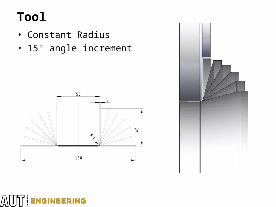
Tool• Constant Radius• 15° angle increment
150
49
56
1
R3
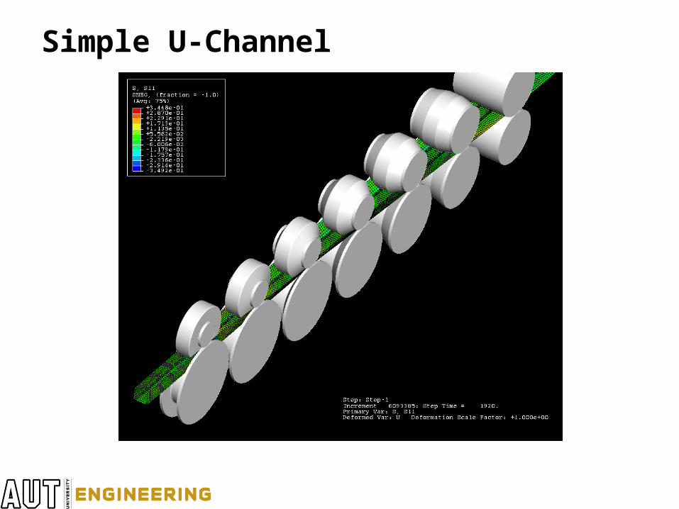
Simple U-Channel
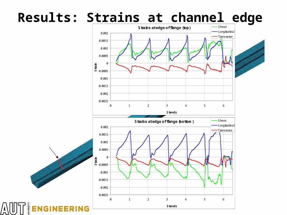
Results: Strains at channel edgeStrains at edge of flange (top)
-0.0025
-0.002
-0.0015
-0.001
-0.0005
0
0.0005
0.001
0.0015
0.002
0 1 2 3 4 5 6
Stands
Str
ain
Shear
Longitudinal
Transverse
Strains at edge of flange (bottom)
-0.0025
-0.002
-0.0015
-0.001
-0.0005
0
0.0005
0.001
0.0015
0.002
0 1 2 3 4 5 6
Stands
Str
ain
Shear
Longitudinal
Transverse
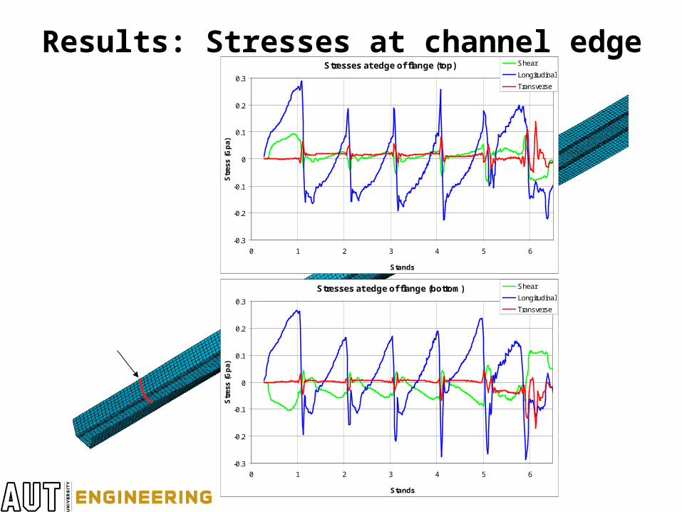
Results: Stresses at channel edgeStresses at edge of flange (top)
-0.3
-0.2
-0.1
0
0.1
0.2
0.3
0 1 2 3 4 5 6
Stands
Str
ess
(Gp
a)
Shear
Longitudinal
Transverse
Stresses at edge of flange (bottom)
-0.3
-0.2
-0.1
0
0.1
0.2
0.3
0 1 2 3 4 5 6
Stands
Str
ess
(Gp
a)
Shear
Longitudinal
Transverse
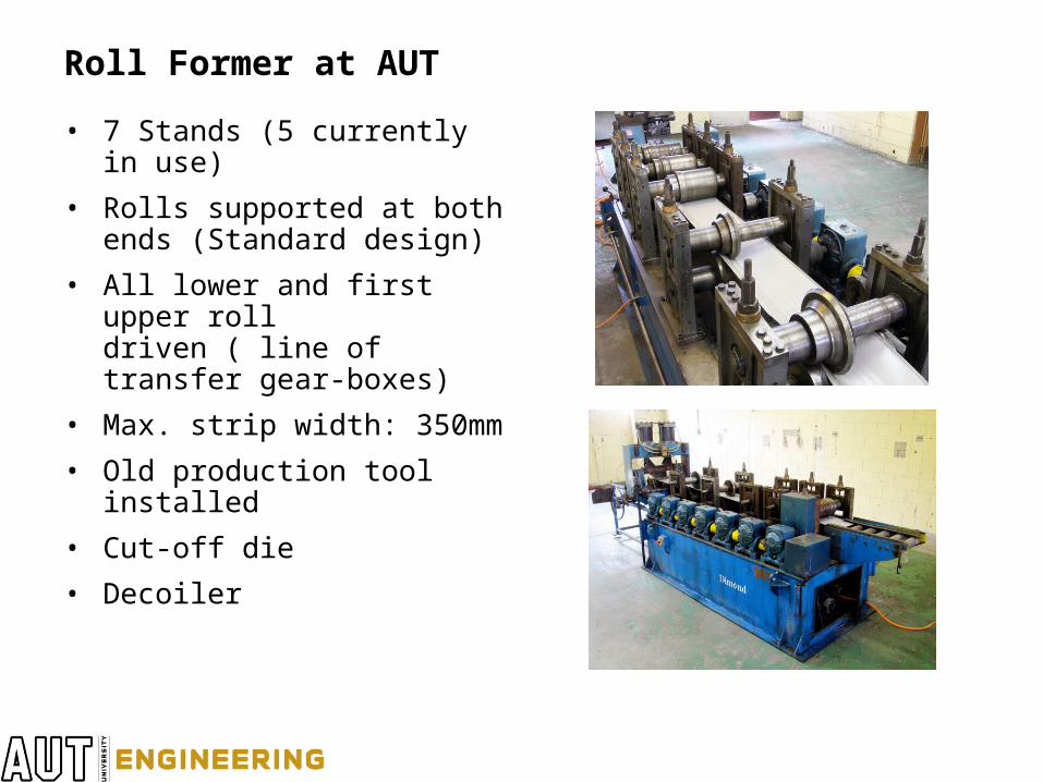
Roll Former at AUT
• 7 Stands (5 currently in use)
• Rolls supported at both ends (Standard design)
• All lower and first upper rolldriven ( line of transfer gear-boxes)
• Max. strip width: 350mm
• Old production tool installed
• Cut-off die
• Decoiler
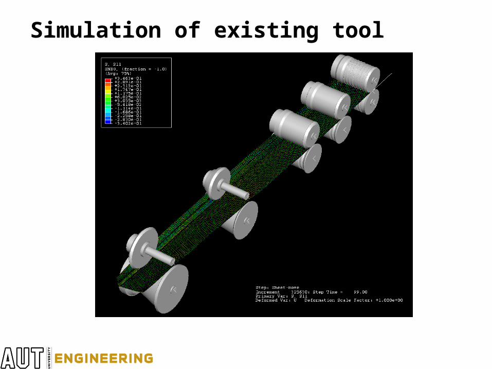
Simulation of existing tool
Summary and future work• New developments
• Created simulation of– U-channel and
– Production tool
• Develop versatile research tool
• Verify simulation
• Progress to more complex geometry
• Develop design aide for roll forming
Thank you


![State-of-the-art premium touchscreen balance series with ... · Analytical balance KERN AET Analytical balance KERN AET [d] 0,01 mg Precision balance KERN PET Industry scale KERN](https://img.pdfslide.us/doc/110x75/5f8e84abb20c024b62363ed0/state-of-the-art-premium-touchscreen-balance-series-with-analytical-balance.jpg)