Embed Size (px)
Citation preview
Simulation of practical single-pixel wire-grid polarizers for superpixel stokesvector imaging arrays
Alan D. RaisanenMichael D. PresnarZoran NinkovKenneth FourspringLingfei MengJohn P. Kerekes
Downloaded from SPIE Digital Library on 09 Feb 2012 to 66.165.46.178. Terms of Use: http://spiedl.org/terms
Simulation of practical single-pixel wire-grid polarizersfor superpixel stokes vector imaging arrays
Alan D. RaisanenMichael D. PresnarRochester Institute of TechnologySemiconductor and Microsystems Laboratory82 Lomb Memorial DriveRochester, New York 14551E-mail: [email protected]
Zoran NinkovKenneth FourspringLingfei MengJohn P. KerekesRochester Institute of TechnologyChester F. Carlson Center for Imaging Science54 Lomb Memorial DriveRochester, New York 14551
Abstract. An optical tracking sensor that produces images containing thestate of polarization of each pixel can be implemented using individualwire-grid micropolarizers on each detector element of a solid-state focalplane array. These sensors can significantly improve identification andtracking of various man-made targets in cluttered, dynamic scenes suchas urban and suburban environments. We present electromagnetic simu-lation results for wire-grid polarizers that can be fabricated on standardimaging arrays at three different technology nodes (an 80-, 250-, and500-nm pitch) for use in polarization-sensitive detector arrays. The degra-dation in polarizer performance with the larger pitch grids is quantified.We also present results suggesting the performance degradation is notsignificant enough to affect performance in a man-made vehicle-trackingapplication. © 2012 Society of Photo-Optical Instrumentation Engineers (SPIE). [DOI:10.1117/1.OE.51.1.016201]
Subject terms: hyperspectral imaging; polarimetry; polarizers; hybrid imaging arrays.
Paper 110580 received May 26, 2011; revised manuscript received Oct. 15, 2011;accepted for publication Nov. 2, 2011; published online Feb. 7, 2012.
1 IntroductionOptically locating and following a moving target through acluttered environment is a challenging task. Target detectionand tracking can be made much more robust by exploitingspecific signatures of an artificial target relative to a naturalbackground, such as spectral characteristics1 (via multispec-tral and hyperspectral imaging) or polarization state.2–4 A sin-gle linear polarizing element in the input optics of a detectorsystem can be rotated to enable collection of the completeStokes vector describing the polarization state of each pixelin an image, but this is only practical for slow-moving or staticscenes.2,5 For rapid data collection of fast-moving scenes atvideo rates, the Stokes vector of the entire scene must be col-lected coincidentally. This can be accomplished by simulta-neously collecting three polarization images for each pixelat 0, 60, and 120 deg linear polarization, for example.6
These polarimetric images may be produced by imaging ascene with multiple cameras, each with a suitable polarizer inthe input optics, but this process can be complicated by theneed to accurately register each camera relative to the others.A more robust solution may be obtained by permanentlyintegrating the polarizer or polarizer array with the imagingdetector in a hybridized configuration. The full Stokes vec-tor can be obtained with this approach by segmenting thepolarizer plus imager array into superpixels composed of2 × 2 pixels, each with a linear polarizer element at a differentangle, as illustrated in Fig. 1(a). This proposed array containssuperpixels with individually polarized elements at 0, 60, and120 deg linear polarization, plus a single unpolarized pixelelement. These arrays can be fabricated by affixing an arrayof wire-grid polarizer elements on an optical element to theimaging array. An alternative approach proposed here avoidsintroducing another set of optical surfaces and avoids thechallenge of aligning and securing the polarizer array on the
imaging array by fabricating a set of pixel-sized wire-gridpolarizer elements directly on each element of the imagingarray. If there is sufficient demand for these devices it isstraightforward to fabricate these hybridized arrays duringthe microfabrication process, but for low-volume and researchpurposes it may be necessary to create the polarizer arrays onan unpackaged commercial imager array.
Some authors have already reported successful integrationof pixel-sized polarizer arrays on optical detectors usingaluminum wire grids fabricated with electron-beam lithogra-phy.7 Very-high-efficiency micropolarizer elements can befabricated using the fine linewidths achievable with e-beamlithography processes. Unfortunately, this process is expen-sive, low throughput, and can potentially degrade opticaldetectors via radiation damage effects. Low-impact optical ornanoimprint lithography can produce a suitable grid patternon each pixel of an imaging array, but the linewidths and spa-cing produced will be tend to be wider than that achievableby an electron-beam lithography process. The advantage isthat the more conventional optical lithography processeswill have much higher throughput and be much cheaper.
The study of lower-cost fabrication processes was part ofan effort looking at MEMS-based adaptive sensors for urbansurveillance applications.8 Simulation of imaging systemsand target tracking algorithms9 using the Rochester Instituteof Technology (RIT)’s digital imaging and remote-sensingimage generation (DIRSIG) model was used to investigatewhether target-detection probability and tracking-path accu-racy can be significantly improved by using polarimetricimaging with even relatively low-efficiency large-spacingpolarizer elements. Detailed optical performance parametersfor these low-efficiency polarizing elements were unavailablein the literature, so we selected three example technologynodes that could realistically produce integrated or add-onsingle-pixel polarizer elements without destroying an existingimaging detector array. We simulated polarizer elements at a500-nm pitch (readily fabricated using high-NA i-line or0091-3286/2012/$25.00 © 2012 SPIE
Optical Engineering 016201-1 January 2012/Vol. 51(1)
Optical Engineering 51(1), 016201 (January 2012)
Downloaded from SPIE Digital Library on 09 Feb 2012 to 66.165.46.178. Terms of Use: http://spiedl.org/terms
deep-UV optical lithography), a 250-nm pitch (fabricatedusing advanced deep-UVoptical lithography), and an 80-nmpitch (achievable using advanced nanoimprint or state-of-the-art immersion optical lithographic processes). The simulatedoptical throughput of these devices was then used to postpro-cess hyperspectral polarization-resolved DIRSIG videosimulations in Mathworks Corporation (Natick, MA, USA)MATLAB analysis software to assess the ability of a trackingalgorithm9 to monitor the position of a number of movingvehicular targets in a simulated cluttered urban scene.
This paper describes the geometry and electromagneticwave propagation modeling of the wire-grid polarizers, theresulting polarization performance, and the impact of thatperformance on the vehicle-tracking application.
2 Geometry and AnalysisWire-grid polarizer arrays were simulated using COMSOLMultiphysics (COMSOL Inc., Burlington, MA) finiteelement modeling software release 3.5a using the two-dimensional (2-D) in-plane hybrid electromagnetic wave
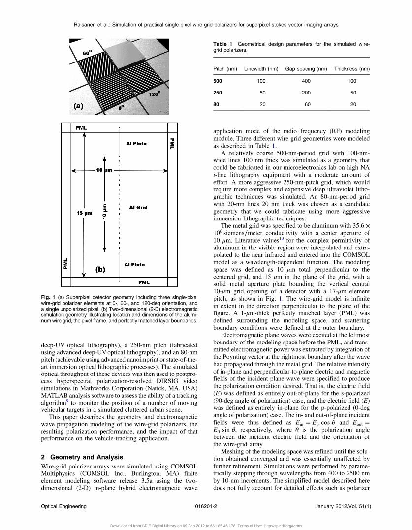
application mode of the radio frequency (RF) modelingmodule. Three different wire-grid geometries were modeledas described in Table 1.
A relatively coarse 500-nm-period grid with 100-nm-wide lines 100 nm thick was simulated as a geometry thatcould be fabricated in our microelectronics lab on high-NAi-line lithography equipment with a moderate amount ofeffort. A more aggressive 250-nm-pitch grid, which wouldrequire more complex and expensive deep ultraviolet litho-graphic techniques was simulated. An 80-nm-period gridwith 20-nm lines 20 nm thick was chosen as a candidategeometry that we could fabricate using more aggressiveimmersion lithographic techniques.
The metal grid was specified to be aluminum with 35.6 ×10⁶ siemens∕meter conductivity with a center aperture of10 μm. Literature values10 for the complex permittivity ofaluminum in the visible region were interpolated and extra-polated to the near infrared and entered into the COMSOLmodel as a wavelength-dependent function. The modelingspace was defined as 10 μm total perpendicular to thecentered grid, and 15 μm in the plane of the grid, with asolid metal aperture plate bounding the vertical central10-μm grid opening of a detector with a 17-μm elementpitch, as shown in Fig. 1. The wire-grid model is infinitein extent in the direction perpendicular to the plane of thefigure. A 1-μm-thick perfectly matched layer (PML) wasdefined surrounding the modeling space, and scatteringboundary conditions were defined at the outer boundary.
Electromagnetic plane waves were excited at the leftmostboundary of the modeling space before the PML, and trans-mitted electromagnetic power was extracted by integration ofthe Poynting vector at the rightmost boundary after the wavehad propagated through the metal grid. The relative intensityof in-plane and perpendicular-to-plane electric and magneticfields of the incident plane wave were specified to producethe polarization condition desired. That is, the electric field(E) was defined as entirely out-of-plane for the s-polarized(90-deg angle of polarization) case, and the electric field (E)was defined as entirely in-plane for the p-polarized (0-degangle of polarization) case. The in- and out-of-plane incidentfields were thus defined as Ein ¼ E0 cos θ and Eout ¼E0 sin θ, respectively, where θ is the polarization anglebetween the incident electric field and the orientation ofthe wire-grid array.
Meshing of the modeling space was refined until the solu-tion obtained converged and was essentially unaffected byfurther refinement. Simulations were performed by parame-trically stepping through wavelengths from 400 to 2500 nmby 10-nm increments. The simplified model described heredoes not fully account for detailed effects such as polarizer
Fig. 1 (a) Superpixel detector geometry including three single-pixelwire-grid polarizer elements at 0-, 60-, and 120-deg orientation, anda single unpolarized pixel. (b) Two-dimensional (2-D) electromagneticsimulation geometry illustrating location and dimensions of the alumi-numwire grid, the pixel frame, and perfectly matched layer boundaries.
Table 1 Geometrical design parameters for the simulated wire-grid polarizers.
Pitch (nm) Linewidth (nm) Gap spacing (nm) Thickness (nm)
500 100 400 100
250 50 200 50
80 20 60 20
Raisanen et al.: Simulation of practical single-pixel wire-grid polarizers for superpixel stokes vector imaging arrays
Optical Engineering 016201-2 January 2012/Vol. 51(1)
Downloaded from SPIE Digital Library on 09 Feb 2012 to 66.165.46.178. Terms of Use: http://spiedl.org/terms
edge termination,11 the gap between polarizer and detec-tor,12 and diffractive effects from the 2-D frame aroundthe polarizer. However, the model provides good qualitativeagreement with more sophisticated approaches using finite-difference time domain methods while remaining computa-tionally simple enough to provide polarizer performancemetrics across a broad range of input wavelengths. Patterningof a wire-grid polarizer array directly on a detector surfaceis also expected to potentially excite near-field effects13
that may produce wavelength-dependent enhancements orsuppressions of both s- and p-polarized radiation, leadingto narrow peaks and valleys in the extinction ratio observedfor a given polarizer. These effects are neglected in thismodel, but might be utilized to improve device performancein specific spectral regions of interest in future work.
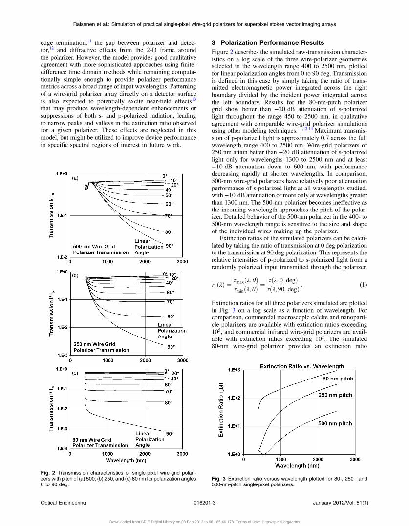
3 Polarization Performance ResultsFigure 2 describes the simulated raw-transmission character-istics on a log scale of the three wire-polarizer geometriesselected in the wavelength range 400 to 2500 nm, plottedfor linear polarization angles from 0 to 90 deg. Transmissionis defined in this case by simply taking the ratio of trans-mitted electromagnetic power integrated across the rightboundary divided by the incident power integrated acrossthe left boundary. Results for the 80-nm-pitch polarizergrid show better than −20 dB attenuation of s-polarizedlight throughout the range 450 to 2500 nm, in qualitativeagreement with comparable wire-grid polarizer simulationsusing other modeling techniques.11,12,14 Maximum transmis-sion of p-polarized light is approximately 0.7 across the fullwavelength range 400 to 2500 nm. Wire-grid polarizers of250 nm attain better than −20 dB attenuation of s-polarizedlight only for wavelengths 1300 to 2500 nm and at least−10 dB attenuation down to 600 nm, with performancedecreasing rapidly at shorter wavelengths. In comparison,500-nm wire-grid polarizers have relatively poor attenuationperformance of s-polarized light at all wavelengths studied,with−10 dB attenuation or more only at wavelengths greaterthan 1300 nm. The 500-nm polarizer becomes ineffective asthe incoming wavelength approaches the pitch of the polar-izer. Detailed behavior of the 500-nm polarizer in the 400- to500-nm wavelength range is sensitive to the size and shapeof the individual wires making up the polarizer.
Extinction ratios of the simulated polarizers can be calcu-lated by taking the ratio of transmission at 0 deg polarizationto the transmission at 90 deg polarization. This represents therelative intensities of p-polarized to s-polarized light from arandomly polarized input transmitted through the polarizer.
reðλÞ ¼τmaxðλ; θÞτminðλ; θÞ
¼ τðλ; 0 degÞτðλ; 90 degÞ : (1)
Extinction ratios for all three polarizers simulated are plottedin Fig. 3 on a log scale as a function of wavelength. Forcomparison, commercial macroscopic calcite and nanoparti-cle polarizers are available with extinction ratios exceeding105, and commercial infrared wire-grid polarizers are avail-able with extinction ratios exceeding 102. The simulated80-nm wire-grid polarizer provides an extinction ratio
Fig. 2 Transmission characteristics of single-pixel wire-grid polari-zers with pitch of (a) 500, (b) 250, and (c) 80 nm for polarization angles0 to 90 deg.
Fig. 3 Extinction ratio versus wavelength plotted for 80-, 250-, and500-nm-pitch single-pixel polarizers.
Raisanen et al.: Simulation of practical single-pixel wire-grid polarizers for superpixel stokes vector imaging arrays
Optical Engineering 016201-3 January 2012/Vol. 51(1)
Downloaded from SPIE Digital Library on 09 Feb 2012 to 66.165.46.178. Terms of Use: http://spiedl.org/terms
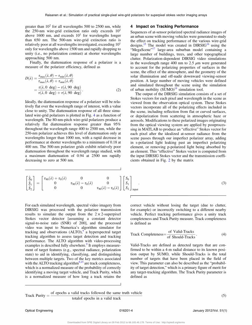
greater than 102 for all wavelengths 500 to 2500 nm, whilethe 250-nm wire-grid extinction ratio only exceeds 102
above 1600 nm, and exceeds 101 for wavelengths longerthan 650 nm. The 500-nm wire-grid extinction ratio isrelatively poor at all wavelengths investigated, exceeding 101
only for wavelengths above 1500 nm and rapidly dropping tounity (i.e., no polarization contrast) at shorter wavelengthsapproaching 500 nm.
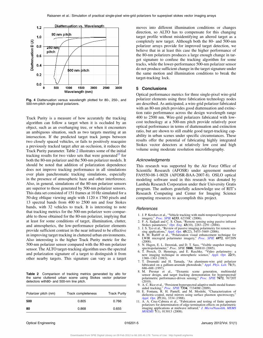
Finally, the diattenuation response of a polarizer is ameasure of the polarizer efficiency, defined as
DðλÞ ¼ τmaxðλ; θÞ − τminðλ; θÞτmaxðλ; θÞ þ τminðλ; θÞ
¼ τðλ; 0 degÞ − τðλ; 90 degÞτðλ; 0 degÞ þ τðλ; 90 degÞ : (2)
Ideally, the diattenuation response of a polarizer will be rela-tively flat over the wavelength range of interest, with a valueclose to unity. The diattenuation response of all three simu-lated wire-grid polarizers is plotted in Fig. 4 as a function ofwavelength. The 80-nm-pitch wire-grid polarizers produce arelatively flat diattenuation response greater than 95%throughout the wavelength range 400 to 2500 nm, while the250-nm polarizer achieves this level of diattenuation only atwavelengths longer than 1000 nm, with a rapid decrease inperformance at shorter wavelengths to a minimum of 0.18 at400 nm. The 500-nm polarizer grids exhibit relatively poordiattenuation throughout the wavelength range studied, witha maximum diattenuation of 0.94 at 2500 nm rapidlydecreasing to zero at 500 nm.
4 Impact on Tracking PerformanceSequences of at-sensor polarized spectral radiance images ofan urban scene with moving vehicles were generated to studythe effect on tracking performance of the various wire-griddesigns.15 The model was created in DIRSIG16 using the“MegaScene”17 large-area suburban model containing alarge number of buildings, trees, and other topographicalclutter. Polarization-dependent DIRSIG video simulationsin the wavelength range 400 nm to 2.5 μm were generatedto account for the polarizing properties of surfaces in thescene, the effect of the atmosphere, and the geometry of thesolar illumination and off-nadir downward viewing-sensorposition. A large number of moving vehicles were definedand simulated throughout the scene using the simulationof urban mobility (SUMO)18 simulation tool.
The output of the DIRSIG simulation consists of a set ofStokes vectors for each pixel and wavelength in the scene asviewed from the observation optical system. These Stokesvectors incorporate all of the polarizing effects included inthe scene, including reflection from flat or curved surfaces,or depolarization from scattering in atmospheric haze oraerosols. Modifications to these polarized images originatingfrom the optical viewing system are applied by postproces-sing in MATLAB to produce an “effective” Stokes vector foreach pixel after the idealized at-sensor radiance from thescene passes through our imperfect polarizer array, addingin s-polarized light leaking past an imperfect polarizingelement, or removing p-polarized light being absorbed byan element. This “effective” Stokes vector is computed fromthe input DIRSIG Stokes vector and the transmission coeffi-cients obtained in Fig. 2 by the matrix
24 S0S1S2
35 ¼
24τ90ðλÞ þ τ0ðλÞ 0 0
0 τ90ðλÞ − τ0ðλÞ 0
0 0 τ90ðλÞ − τ0ðλÞ
3524S0S1S2
35input
: (3)
For each simulated wavelength, spectral video imagery fromDIRSIG was processed with the polarizer transmissionresults to simulate the output from the 2 × 2-superpixelStokes vector detector [assuming a constant detectorsignal-to-noise ratio (SNR) of 200], and the processedvideo was input to Numerica’s algorithm simulator fortracking and observations (ALTO),9 a hyperspectral targettracking algorithm to assess target detection and trackingperformance. The ALTO algorithm with video-processingexamples is described fully elsewhere.9 It employs measure-ment of target features (e.g., spectral radiance, polarizationstate) to aid in identifying, classifying, and distinguishingbetween multiple targets. Two of the key metrics associatedwith the ALTO tracking algorithm9,15 are track completeness,which is a normalized measure of the probability of correctlyidentifying a moving target vehicle, and Track Purity, whichis a normalized measure of how long a track retains the
correct vehicle without losing the target (due to clutter,for example) or incorrectly switching to a different nearbyvehicle. Perfect tracking performance gives a unity trackcompleteness and Track Purity measure. Track completenessis defined as
Track Completeness¼ of Valid-Tracks
of Should-Tracks: (4)
Valid-Tracks are defined as detected targets that are con-firmed to be within a 4-m radial distance to its known posi-tion output by SUMO, while Should-Tracks is the totalnumber of targets that have been placed in the field ofview. This parameter can also be described as the “probabil-ity of target detection,” which is a primary figure of merit forany target-tracking algorithm. The Track Purity parameter isdefined as
Track Purity ¼ of epochs a valid tracks followed the same truth vehicle
totalof epochs in a valid track(5)
Raisanen et al.: Simulation of practical single-pixel wire-grid polarizers for superpixel stokes vector imaging arrays
Optical Engineering 016201-4 January 2012/Vol. 51(1)
Downloaded from SPIE Digital Library on 09 Feb 2012 to 66.165.46.178. Terms of Use: http://spiedl.org/terms
Track Purity is a measure of how accurately the trackingalgorithm can follow a target when it is occluded by anobject, such as an overhanging tree, or when it encountersan ambiguous situation, such as two targets meeting at anintersection. If the predicted target track jumps betweentwo closely spaced vehicles, or fails to positively reacquirea previously tracked target after an occlusion, it reduces theTrack Purity parameter. Table 2 illustrates some of the initialtracking results for two video sets that were generated15 forboth the 80-nm polarizer and the 500-nm polarizer models. Itshould be noted that addition of polarization dependencedoes not improve tracking performance in all simulationsover plain panchromatic tracking simulations, especiallyin the presence of atmospheric haze and other interference.Also, in general, simulations of the 80-nm polarizer sensorsare superior to those generated by 500-nm polarizer sensors.This data set consisted of 151 frames at 10 Hz simulated for a50-deg oblique viewing angle with 1120 × 1760 pixels and13 spectral bands from 400 to 2500 nm and four Stokesbands, with 32 vehicles to track. It is interesting to notethat tracking metrics for the 500-nm polarizer were compar-able to those obtained for the 80-nm polarizer, implying thatat least for some conditions of target, illumination, clutter,and atmospherics, the low-performance polarizer elementsprovide sufficient contrast in the near infrared to be effectivein improving target tracking in cluttered urban environments.Also interesting is the higher Track Purity metric for the500-nm polarizer sensor compared with the 80-nm polarizersensor. The ALTO target-tracking algorithm uses the spectraland polarization signature of a target to distinguish it fromother nearby targets. This signature can vary as a target
moves into different illumination conditions or changesdirection, so ALTO has to compensate for this changingtarget profile without misidentifying an altered target as acompletely new target. Although both the 80- and 500-nmpolarizer arrays provide for improved target detection, webelieve that in at least this case the higher performance ofthe 80-nm polarizers produces a large enough change in tar-get signature to confuse the tracking algorithm for sometracks, while the lower-performance 500-nm polarizer sensordo not produce sufficient change in the target signature underthe same motion and illumination conditions to break thetarget-tracking lock.
5 ConclusionsOptical performance metrics for three single-pixel wire-gridpolarizer elements using three fabrication technology nodesare described. As anticipated, a wire-grid polarizer fabricatedwith an 80-nm pitch provides good diattenuation and extinc-tion ratio performance across the design wavelength range400 to 2500 nm. Wire-grid polarizers fabricated with low-cost technology at a 500-nm pitch provide relatively pooroptical performance in terms of diattenuation and extinctionratio, but are shown to still enable good target-tracking cap-ability in urban scenes under specific circumstances. Theseresults offer the potential of fabricating highly integratedStokes vector detectors at relatively low cost and highvolume using moderate resolution microlithography.
AcknowledgmentsThis research was supported by the Air Force Office ofScientific Research (AFOSR) under agreement numberFA9550-08-1-0028 (AFOSR-BAA-2007-8). OSLO opticalmodeling software used in this research was donated byLambda Research Corporation under their University Gratisprogram. The authors gratefully acknowledge use of RIT’sResearch Computing and Center for Imaging Sciencecomputing resources to accomplish this project.
References
1. J. P. Kerekes et al., “Vehicle tracking with multi-temporal hyperspectralimagery,” Proc. SPIE 6233, 62330C (2006).
2. F. A. Sadjadi and C. S. Chun, “Remote sensing using passive infraredStokes parameters,” Opt. Eng. 43(10), 2283–2291 (2004).
3. J. S. Tyo et al., “Review of passive imaging polarimetry for remote sen-sing applications,” Appl. Opt. 45(22), 5453–5469 (2006).
4. B. M. Ratliff et al., “Polarization visual enhancement technique forLWIR microgrid polarimeter imagery,” Proc. SPIE 6972, 69720N(2008).
5. N. Hagen, E. L. Dereniak, and D. T. Sass, “Visible snapshot imagingspectropolarimeter,” Proc. SPIE 5888, 588810 (2005).
6. T. Prosch, D. Hennings, and E. Raschke, “Video polarimetry: anew imaging technique in atmospheric science,” Appl. Opt. 22(9),1360–1363 (1983).
7. T. Doumuki and H. Tamada, “An aluminum-wire grid polarizerfabricated on a gallium-arsenide photodiode,” Appl. Phys. Lett. 71(5),686–688 (1997).
8. M. Presnar et al., “Dynamic scene generation, multimodalsensor design, and target tracking demonstration for hyperspectral/polarimetric performance-driven sensing,” Proc. SPIE 7672, 76720T(2010).
9. A. C. Rice et al., “Persistent hyperspectral adaptive multi-modal feature-aided tracking,” Proc. SPIE 7334, 73340M (2009).
10. E. Fontana, R. H. Pantell, and M. Moslehi, “Characterization ofdielectric-coated, metal mirrors using surface plasmon spectroscopy,”Appl. Opt. 27(16), 3334 (1988).
11. A. A. Cruz-Cabrera et al., “Fabrication and testing of finite aperturepolarizers for determination of edge termination effects on polarimetricimaging applications at midwave infrared,” J. Micro/Nanolith. MEMSMOEMS 7(1), 013013 (2008).
Fig. 4 Diattenuation versus wavelength plotted for 80-, 250-, and500-nm-pitch single-pixel polarizers.
Table 2 Comparison of tracking metrics generated by alto forthe same cluttered urban scene using Stokes vector polarizerdetectors with80- and 500-nm line pitch.
Polarizer pitch (nm) Track completeness Track Purity
500 0.805 0.766
80 0.868 0.655
Raisanen et al.: Simulation of practical single-pixel wire-grid polarizers for superpixel stokes vector imaging arrays
Optical Engineering 016201-5 January 2012/Vol. 51(1)
Downloaded from SPIE Digital Library on 09 Feb 2012 to 66.165.46.178. Terms of Use: http://spiedl.org/terms

12. A. A. Cruz-Cabrera et al., “Polarimetric imaging cross talk effects fromglue separation between FPA and micropolarizer arrays at the MWIR,”Proc. SPIE 6478 , 64780Q (2007).
13. D. C. Skigin and M. Lester, “Study of resonant modes of a periodicmetallic array near a dielectric interface: evanescent-to-propogatingcoupling via surface plasmon excitation,” J. Opt. A: Pure Appl. Opt.8(3), 259–267 (2006).
14. M. A. Jensen and G. P. Nordin, “Finite-aperture wire grid polarizers,” J.Opt. Soc. Am. A 17(12), 2191–2198 (2000).
15. M. D. Presnar, “Modeling and simulation of adaptive multimodaloptical sensors for target tracking in the visible to near infrared,”PhD Dissertation, Rochester Institute of Technology, Center for Ima-ging Science (2010).
16. J. S. Sanders and S. D. Brown, “Utilization of DIRSIG in supportof real-time infrared scene generation,” Proc. SPIE 4029, 278(2000).
17. E. J. lentilucci and S. D. Brown, “Advances in wide-area hyperspectralimage simulation,” Proc. SPIE 5075, 110–121 (2003).
18. D. Krajzewicz et al., “SUMO (simulation of urban mobility); an open-source traffic simulation,” in 4th Middle East Symposium on Simulationand Modelling (MESM2002), pp. 183–187 (2002).
Alan D. Raisanen received his BS degree inphysics from Drake University, Des Moines,Iowa, in 1985 and his PhD in materialsscience and engineering in 1992. He joinedRochester Institute of Technology as a tech-nical staff member in 2001. His currentresearch focuses on use of microfabricationtechniques to implement microsystemsfor imaging, detection, and biomedicalapplications.
Michael D. Presnar received a BS in chemi-cal engineering together with a BS in electri-cal engineering from Michigan TechnologicalUniversity, Houghton, Michigan, in 1995; anMS in electrical engineering together withan MS in applied mathematics from the AirForce Institute of Technology, Dayton, Ohio,in 2000; and his PhD in imaging sciencefrom the Rochester Institute of Technology,Rochester, New York, in 2010. He is currentlyan officer in the United States Air Force.
Zoran Ninkov is a professor in the Centerfor Imaging Science (CIS) at the RochesterInstitute of Technology. He completed hisBSc in physics at the University of WesternAustralia, MS in chemistry at MonashUniversity, and his PhD in astronomy at theUniversity of British Columbia. He was apostdoctoral fellow at the University ofRochester working on infrared detectorarray for the Spitzer Space Telescope. Hesubsequently spent time at the DSTO in
Adelaide, Australia, and at ISTS in Toronto before joining CIS. Hisresearch interests are in detectors and instrumentation.
Lingfei Meng received his BS degree inelectrical engineering from the Tianjin Univer-sity, China, in 2007. He is currently pursuinghis PhD degree in imaging science at theRochester Institute of Technology, NewYork. His research interests include imagingsystem modeling, digital image processing,and computer vision.
John P. Kerekes received a BS, MS, andPhD in electrical engineering from PurdueUniversity, West Lafayette, Indiana, in 1983,1986, and 1989, respectively. From 1989until 2004 he was a technical staff memberat MIT Lincoln Laboratory in Lexington,Massachusetts. Since 2004 he has been anassociate professor at the Chester F. CarlsonCenter for Imaging Science at the RochesterInstitute of Technology. His research inter-ests include pattern recognition, image
processing, and remote-sensing system modeling.
Biographies and photographs of the other authors are not available.
Raisanen et al.: Simulation of practical single-pixel wire-grid polarizers for superpixel stokes vector imaging arrays
Optical Engineering 016201-6 January 2012/Vol. 51(1)
Downloaded from SPIE Digital Library on 09 Feb 2012 to 66.165.46.178. Terms of Use: http://spiedl.org/terms