Embed Size (px)
Citation preview

Simulation of NOx Emission in Circulating Fluidized Beds BurningLow-grade Fuels†
Afsin Gungor*
Nigde UniVersity, Faculty of Engineering and Architecture, Department of Mechanical Engineering,51100 Nigde, Turkey
ReceiVed December 12, 2008. ReVised Manuscript ReceiVed February 17, 2009
Nitrogen oxides are a major environmental pollutant resulting from combustion. This paper presents amodeling study of pollutant NOx emission resulting from low-grade fuel combustion in a circulating fluidizedbed. The simulation model accounts for the axial and radial distribution of NOx emission in a circulatingfluidized bed (CFB). The model results are compared with and validated against experimental data both forsmall-size and industrial-size CFBs that use different types of low-grade fuels given in the literature. Thepresent study proves that CFB combustion demonstrated by both experimental data and model predictionsproduces low and acceptable levels of NOx emissions resulting from the combustion of low-grade fuels.Developed model can also investigate the effects of different operational parameters on overall NOx emission.As a result of this investigation, both experimental data and model predictions show that NOx emission increaseswith the bed temperature but decreases with excess air if other parameters are kept unchanged.
Introduction
Circulating fluidized bed (CFB) combustion is receiving wideresearch attention in view of its potential as an economic andenvironmentally acceptable technology for burning low-gradecoals. In addition to highly efficient operation, a combustionsystem should comply with the requirement of minimizingenvironmental impact. The emission rate of various pollutantsfrom the combustion of coal depends on fuel analysis, combustordesign, and operating conditions. Fluidized bed combustionallows clean and efficient combustion of coal. Designing of theCFB combustor (CFBC) is very important because of burningcoal with high efficiency and within acceptable levels of gaseousemissions. A good understanding of the combustion andpollutant generating processes in the combustor can greatlyavoid costly upsets. One of the major advantages of CFBCs istheir efficiency for combustion of low-grade lignites.1,2
Nitrogen oxides are a major environmental pollutant resultingfrom combustion. The reactions of nitrogen oxides with carbonsor chars are of current interest with regard to their possible rolein reducing NOx emissions from combustion systems. They alsooffer new useful insights into the oxidation reactions of carbons,generally.3 A large amount of literature concerning thesereactions has developed, as evidenced in three reviews4-6 andby the recent publication of many papers in the area.1,7,8 Theseworks have suggested considerable complexity in the mecha-
nisms of NOx reduction and a large variability in reportedkinetics. There are two approaches to describe NOx emissionin CFB.9 The first approach involves overall reaction (consider-ing catalytic activity of CaO and char). The overall rate constantsare measured preferably under CFB conditions.10 The otherapproach is more thorough and is based on actual chemicalreactions whose rate constants can be taken from literature.11
For CFB only 106 reactions with 28 species were used to modelthe NOx emission. However, a detailed review shows that allN-related reactions have not the same importance.12 So insteadof considering all N-related reactions, one could use only theimportant reactions for the development of a predictive proce-dure for the overall NOx emission from a CFBC.
The objective of the model presented in this study is to beable to predict the pollutant emissions formation and destructionof different low-grade Turkish lignites in various sizes ofCFBCs. There are considerable reserves of lignite in Turkey.Most of Turkish lignite reserves are of low-grade lignites witha calorific value of about 12 000 kJ/kg, ash content of about25-30%, and average sulfur content of about <4%. The mainproblem for Turkish units running on lignite is presented bythe air emissions.13
For the reduction of pollutant emissions from coal fired powerplants, numerous techniques, involving the staged input of fueland air, have been successfully applied. The application of thesetechniques to industrial-scale combustors necessitates combus-
† Presented at the 10th International Combustion Symposium, ICS-2008,Turkey, November 9-10, 2008.
* Phone: +90 532 397 30 88; fax: +90 388 225 01 12; e-mail:[email protected].
(1) Bosoaga, A.; Panoiu, N.; Mihaescu, L.; Backreedy, R. I.; Ma, L.;Pourkashanian, M.; Williams, A. Fuel 2006, 85 (10-11), 1591–1598.
(2) Ozkan, G.; Dogu, G. Chem. Eng. Proc. 2002, 41 (1), 11–15.(3) Aarna, I.; Suuberg, E. M. Energy Fuels 1999, 13, 1145–1153.(4) Aarna, I.; Suuberg, E. M. Fuel 1997, 76, 475–482.(5) Li, Y. H.; Lu, G. Q.; Rudolph, V. Chem. Eng. Sci. 1998, 53, 1–7.(6) Aoki, H.; Suzuki, A.; Hisaeda, Y.; Suwa, Y.; Nakagawa, T.; Yaga,
M.; Shoji, M.; Miura, T. Heat Trans. Asian Res. 2001, 30 (7), 581–612.(7) Liu, H.; Feng, B.; Lu, J. D. Chem. Eng. Commun. 2005, 192 (10-
12), 1482–1489.
(8) Gungor, A.; Eskin, N. Int. J. Thermal Sci 2008, 47, 157–174.(9) Winter, F. Single Fuel Particle and NOx/N2O-Emission Character-
istics Under Circulating Fluidized Bed Combustor Conditions; Ph.D. Thesis,University of Technology: Vienna, Austria, 1995.
(10) Stenseng, M. Lin, W.; Johnsson, J. E.; Johansen, K. D. Modelingof devolatilization in CFB combustion, Presented at the 14th InternationalConference on Fluidized Bed Combustion; ASME, New York, 1997.
(11) Kilpinen, P.; Glarborg, P.; Hupa, M. Ind. Eng. Chem. Res. 1992,31, 1477–1490.
(12) Talukdar, J.; Basu, P. Can. J. Chem. Eng. 1995, 73, 635–643.(13) Gungor, A. Modeling of circulating fluidized bed combustors; Ph.D.
Thesis, Istanbul Technical University Institute of Science and Technology:Turkey, 2006.
Energy & Fuels 2009, 23, 2475–2481 2475
10.1021/ef8010838 CCC: $40.75 2009 American Chemical SocietyPublished on Web 04/08/2009
tion parameters optimization that is extremely time-consumingand expensive. Mathematical modeling allows the testing ofmany variable combustion parameters in a much shorter timeperiod and at lower costs. Therefore, mathematical modelingapplication in the CFB combustion process to enhance combus-tion performance and to reduce pollutants is seen as an attractivesolution. This paper presents a modeling study of NOx pollutantemission resulting from coal combustion in a CFBC. Using thismodel, overall NOx emission is predicted for the combustionof three different kinds of low-grade Turkish lignites. Thecontents of these lignites are as follows: ash from 23.70 to45.31%, sulfur from 1.81 to 8.40%, and calorific values (LHV)from 10 283 to 15 215 kJ/kg. The data is obtained from twopilot scale CFBCs (50 and 80 kW) and an industrial scale CFBC(160 MW). The developed model can also investigate the effectsof different operational parameters on overall NOx emission.
Model Description. On the basis of previous work ondynamic two-dimensional (2D) coal combustion modeling ofCFBCs,8 a modeling study of pollutant emissions resulting fromcoal combustion in CFBCs is present in this study. The presentCFBC model can be divided into three major parts: a submodelof the gas-solid flow structure; a reaction kinetic model forlocal combustion; and a convection/dispersion model withreaction. The latter formulates the mass balances for the gaseousspecies and the char at each control volume in the flow domain.Kinetic information for the reactions is supplied by the reactionkinetic submodel, which contains a description of devolatiliza-tion and char combustion, and emission formation and destruc-tion, respectively.
Hydrodynamics Structure. Combustor hydrodynamic ismodeled taking into account a previous work.14 The modeladdressed in this paper uses a particle-based approach thatconsiders 2D motion of single particles through fluids. Accord-ing to the axial solid volume concentration profile, the riser isaxially divided into the bottom zone and the upper zone. Thebottom zone in the turbulent fluidization regime is modeled indetail as two-phase flow that is subdivided into a solid-freebubble phase and a solid-laden emulsion phase. A single-phaseback-flow cell model is used to represent the solid mixing inthe bottom zone. A two-phase model is used for gas phasematerial balance. In the upper zone core-annulus solids flowstructure is established. It is assumed that the particles moveupward axially and move from core to the annulus regionradially. Thickness of the annulus varies according to the bedheight. In the annulus region, the particle has a zero normalvelocity. The pressure drop through the bottom zone is equalto the weight of the solids in this region and is considered onlyin the axial direction. In the upper zone, pressure drop due tothe hydrodynamic head of solids is considered in the axialdirection while pressure drop due to solids acceleration is alsoconsidered in the axial and radial directions. The solids frictionand gas friction components of pressure drop are considered asboundary conditions in momentum equations for solid and gasphases, respectively in the model. Solids friction is defined asthe frictional force between the solids and the wall, wheres thegas friction is the frictional force between the gas and the wall.
The hydrodynamic model takes into account the axial andradial distribution of voidage and velocity, for gas and solidphase, pressure drop for gas phase, and solids volume fractionand particle size distribution for solid phase. In order todetermine the validity of the hydrodynamic model, the modelresults are compared with test results using the same inputvariables in the tests as the simulation program input. Hydro-
dynamic model results are compared with experimental resultsobtained from various CFB test rigs at different size in theliterature, where ranges are as follows: bed diameter from 0.05to 0.418 m, bed height from 5 to 18 m, mean particle diameterfrom 67 to 520 µm, particle density from 1398 to 2620 kg/m3,mass fluxes from 21.3 to 300 kg/m2s, and gas superficialvelocities from 2.52 to 9.1 m/s. The model compares withexperimental results for void fraction, solids volume fraction,and particle velocity along the bed height and bed radius anddifferent bed operational parameters prove the model hydro-dynamic structure validation axially and radially. Additionally,inward solids mass flux along the bed radius and pressuregradient along the bed height is validated.14 The structure anddetails of the hydrodynamic model are given in a previousstudy.14 As some of the results of the model, the variation inmean particle diameter and superficial velocity does affect thepressure especially in the core region, and it does not affectconsiderably the pressure in the annulus region. The radialpressure profile is getting flatter in the core region as the meanparticle diameter increases. Similar results can be obtained forlower superficial velocities. It has also been found that thecontribution to the total pressure drop by gas and solids frictioncomponents is negligibly small when compared to the accelera-tion and solids hydrodynamic head components. At the bottomof the riser, in the core region the acceleration component ofthe pressure drop in total pressure drop changes from 0.65 to0.28% from the riser center to the core-annulus interface,respectively; within the annulus region the acceleration com-ponent in total pressure drop changes from 0.22 to 0.11%radially from the core-annulus interface to the riser wall. Onthe other hand, the acceleration component weakens as it movesupward in the riser, decreasing to 1% in both regions at the topof the riser, which is an important indicator of the fact that thehydrodynamic head of solids is the most important factor inthe total pressure drop.
Kinetic Model. The combustor model takes into account thedevolatilization of coal and subsequent combustion of volatilesfollowed by residual char. As a result of the experimental studiescarried out using various types of Turkish lignite, it is knownthat volatilization products enter the upper region in fluid bedsworking at slower rates than CFBs.15,16 In the model, volatilesare entering the combustor with the fed coal particles. It isassumed that the volatiles are released in emulsion phase inthe bottom zone of the CFBC at a rate proportional to the solidmixing rate. The degree of devolatilization and its rate increasewith increasing temperature. The composition of the productsof devolatilization in weight fractions is estimated from thecorrelations proposed by Loison and Chauvin.17
The bed material in the combustor consists of coal, inertparticles, and limestone. The properties and size distribution ofparticles have significant influence on the hydrodynamics andcombustion behavior in the CFBC.18 The model also considersthe particle size distribution due to fuel particle fragmentation,19
char combustion,20 and particle attrition.21 Particles in the model
(14) Gungor, A.; Eskin, N. Powder Technol. 2007, 172, 1–13.
(15) Palmer, C. A.; Tuncali, E.; Dennen, K. O.; Coburn, T. C.;Finkelman, R. B. Int. J. Coal Geo 2004, 60 (2-4), 85–115.
(16) Kucuk, A.; Kadioglu, Y.; Gulaboglu, M. S. Combust. Flame 2003,133 (3), 255–261.
(17) Loison, R.; Chauvin, R. Chem. et. Ind. 1964, 91, 269–274.(18) Wang, Q.; Luo, Z.; Ni, M.; Cen, K. Chem. Eng. J. 2003, 93, 121–
133.(19) Hannes, J.; Renz, U.; Van den Bleek, C. M. The IEA model for
circulating fluidized bed combustion, Presented at the 13th InternationalConference on Fluidized Bed Combustion; ASME, Orlando, 1995.
(20) Hua, Y.; Flamant, G.; Lu, J.; Gauthier, D. Chem. Eng. Proc. 2003,43 (8), 971–978.
2476 Energy & Fuels, Vol. 23, 2009 Gungor
are divided into 10 size groups in the model. The Sauter meandiameter is adopted as average particle size. Particles in thebottom zone include particles coming from the solid feed andrecirculated particles from the separator.
Kinetics of char combustion is modeled with a shrinking corewith attiring shell, that is, the dual shrinking-core model(assuming that the ash separated once formed) with mixedcontrol by chemical reaction and gas film diffusion. The charcombustion at each control volume is considered according tothe reaction
C + 1Φ
O2 f (2 - 2Φ)CO + ( 2
Φ- 1)CO2 (1)
and the char combustion reaction rate, kc, is calculated asfollows:20,22
kc )RuT/Mc
1kcr
+ 1kcd
(kgs )kcr ) 8710 exp(-1.4947 × 10⁸
RuT )( kg
m2s·kPa)kcd )
12ShΦDg
dpRgT ( kg
m2s·kPa)Sh )kgdp
Dg) 2ε + 0.69(Rep
ε )1/2Sc
1/3
(2)
In the model, the attrition constant value is taken as 2 × 10⁻⁷
for the coal particles in the model calculations in both bottomzone and upper zone and the attrition constant value of the coalash particles is taken as 1.7 × 10⁻⁷ as presented in.15,16
For the estimation of combustion efficiency (as percentageof the LHV), the heat losses owing to incomplete combustion(accounting the CO emission) and unburned carbon containedin particular matter are determined.23 In addition to thisdefinition, the losses due to the flue gases to ambient and dueto the bed-to-wall heat transfer are taken into account for theestimation of combustion efficiency in this study. According tothe this assumption the combustion efficiency of CFBC basedon the losses can be defined as follows:
η ) 1 -Qunburnt carbon + Qash + Qunburnt CO + Qfluegases + Qwall
Heat rate of fuel(3)
NOx Emission. It was shown in the literature that24 ratherlow NOx emissions are obtained by staged combustion in a
fluidized bed combustor. By the use of primary and secondaryair injected at different locations in a circulating fluidized bedcombustor, its temperature and combustion atmosphere is well-regulated, and generally low NOx emissions of about 150-350ppm are reported.25
It is crucial to well evaluate the mechanism of NOx formationto reduce NOx in the combustor. However, the mechanism ofNOx formation is complex. NOx formations in combustionprocesses result from a combination of a thermal generationprocess and fuel nitrogen oxidation. At very high temperatures,thermal generation of NOx from the air nitrogen becomes veryimportant, whereas at low temperatures found in a CFBC, thedominant source of NOx is fuel-nitrogen oxidation.4-6 Typically,significant amounts of the fuel-nitrogen remain in the char afterthe devolatilization. The oxidation of this char-nitrogen givesan important contribution to the total nitrogen oxide emissionsfrom the combustor. The mechanism of char-nitrogen oxidationto the products is very complex, and includes not only severalhomogeneous and heterogeneous reactions but also mass transfereffects inside the pore system of the char and in the boundarylayer surrounding the particle.25 In the present study, fuel-NOx
can be formed through combustion of the nitrogenous speciesreleased with volatile matter (such as HCN, NH3) and oxidationof the nitrogen retained in the char. These reactions, resultingin rapid formation of NOx, are most likely to proceed in thebottom zone. Meanwhile, in zones with volume O2 concentra-tions lower than 10-12%, the NH3 concentration is probablyelevated due to the rapid formation of NH3 from HCN26 as wellas because of the emission of NH3 released with volatiles fromfuel particles present in these zones. In the upper zone (withlower O2 concentrations) this may lead to NOx reduction throughits reaction with NH3, followed by formation of nitrogen gasand water vapor, that is, neutral products. The alternativemechanisms of NOx reduction in the upper zone involvereactions of NOx with carbon and CO on the char surface,27
which are highly probable when firing high-ash fuels. Thechemical reactions with their corresponding reaction rates forNOx emissions formation and retention in the model are givenin Table 1. It must be noted that nitrogen oxides generallyoriginate form fuel-nitrogen in forms of NO, NO2 and N2O,whereas the model takes into account NO and N2O as nitrogenoxides. In this study, only NO is considered in the simulation.
(21) Wang, Q.; Luo, Z.; Li, X.; Fang, M.; Ni, M.; Cen, K. Energy 1999,24, 633–653.
(22) Field, M. A.; Gill, D. W.; Morgan, B. B.; Hawksley, P. W. G.Coal Util. Res. Assoc. 1967, 31 (6), 285–292.
(23) Basu, P.; Cen, K. F.; Jestin, L., Boilers and Burners; Springer,New York, 2000.
(24) Zhao, J.; Brereto, C.; Grace, J. R.; Lim, C. J.; Legros, R. Fuel1997, 76 (9), 853–860.
(25) (a) Plass, L. Bierbach, H.; Gummel, P. Experience with Combustionin Circulating Fluidized Beds, Lurgi GmbH. Gervinusstra�e, Frankfurt, 17-19, 1986. (b) Kilpinen, P.; Kallio, S.; Konttinen, J.; Barisic, V. Fuel 2002,81, 2349–2362.
(26) Winter, F.; Wartha, C.; Hofbauer, H. Bioresour. Technol. 1999,70 (1), 39–49.
(27) Werther, J.; Saenger, M.; Hartge, E.-U.; Ogada, T.; Siagi, Z. Prog.Energy Combust. Sci. 2000, 26 (1), 1–27.
Table 1. The NOx Reactions and Reaction Rates used in the Model8
reaction reaction rate
HCN + 1/2O2 f CNO k ) 2.14 × 10⁵ exp(-10 000/T) RHCN ) kCO2CHCN (mol/(m3 s))CNO + 1/2O2 f NO + CO (k2)/(k1) ) 1.02 × 10⁹ exp(-25 460/T) RCNO-O2 ) kCO2CHCN(k1/(k1 + k2CNO)) (mol/(m3 s))CNO + NO f N2O + CO k ) 2.14 × 10⁵ exp(-10 000/T) RCNO-NO ) kCO2CHCN((k2CNO)/(k1 + k2CNO)) (mol/(m3 s))N2O + C f N2 + CO k ) 2.9 × 10⁹ exp(-16 983/T) RN2OC ) kNπdc
2CN2O (mol/s)N2O + CO f N2 + CO2 k ) 5.01 × 10¹³ exp((-4.40 × 10⁴)/(RuT)) RN2O-CO ) kCN2OCCO (mol/(cm3 s))N2O + 1/2O2 f N2 + O2 k ) 1.00 × 10¹⁴ exp((- 2.80 × 10⁴)/(RuT)) RN2O-O2 ) kCN2OCO2 (mol/(cm3 s))NO + C f 1/2N2 + CO k ) 5.85 × 10⁷ exp (-12 000/T) RNOC ) kNπdc
2CNO (mol/s)NO + 1/2C f 1/2N2 + 1/2CO2 k ) 1.3 × 10⁵ exp(-17 111/T) R2NOC ) kNπdc
2CNO (mol/s)NO + CO f 1/2N2 + CO2 KT ) 1.952 × 10¹⁰ exp (-19 000/T) RNOCO ) KT((k1CNO(k2CCO + k3)))/((k1CNO + k2CCO + k3)) (mol/(m3 s))
k1 ) 0.1826k2 ) 0.00786k3 ) 0.002531
NH3 + 5/4O2 f NO + 3/2H2O k ) 2.73 × 10¹⁴ exp(-38 160/T) RNH3NO ) kCNH3CO2 (mol/(m3 s))NH3 + 3/4O2 f 1/2N2 + 3/2H2O k ) 3.38 × 10⁷ exp(-10 000/T) RNH3N2 ) (kCNH3CO2)/(CO2 + k′) (mol/(m3 s))
k′ ) 0.054NO + NH3 + 1/2O2 f N2 + 3/2H2O k ) 1.1 × 10¹² exp(-27 680/T) RNONH3 ) k�CO2�CNH3�CNO (mol/(m3 s))
Simulation of NOx Emission in CFBs Energy & Fuels, Vol. 23, 2009 2477

Numerical Solution. The model allows dividing the calcula-tion domain into mn control volumes, in the radial and the axialdirections and in the core and the annulus regions, respectively.In this study the calculation domain is divided into 8 × 50control volumes in the radial and the axial directions and in thecore and the annulus regions, respectively (Figure 1). With thecylindrical system of coordinates, a symmetry boundary condi-tion is assumed at the column axis. The set of differentialequations governing mass, momentum, and energy for the gasand solid phases are given in detail in a previous study8 andare solved with a computer code developed by the author inFORTRAN language where the time step is 10-6 seconds (Table2). The Gauss-Seidel iteration, which contains a successfulrelaxation method, and combined relaxation Newton-Raphsonmethods are used for solving procedure. Details about thesolving procedure are given elsewhere.8
Inputs for the model are combustor dimensions and construc-tion specifications (insulation thickness and materials), primaryand secondary air flow rates, coal feed rate and particle sizedistribution, coal properties, Ca/S ratio, limestone particle size
distribution, inlet pressure and temperature, ambient temperature,and the superficial velocity. The secondary air injection affectsthe concentration of oxygen, the bed voidage with increasinggas flow rate, the velocity profiles of the gas and the solidphases, and the overall bed temperature. A continuity conditionis used for the gas phase at the top of the cyclone. The cycloneis considered to have 98% collection efficiency. The simulationmodel calculates the axial and radial distribution of voidage,velocity, particle size distribution, pressure drop, gas emissions,and temperature at each time interval for gas and solid phasesboth for dense bed and for riser. While investigating the effectsof operational parameters, the mean bed temperature value isconsidered as 850 °C.
Comparison Data. The comparison data are obtained fromthree different size CFBC, which use different kinds of low-grade Turkish lignites, the 50 kW pilot scale CFBC usingBeypazari lignite, the 80 kW pilot scale CFBC using Tuncbileklignite, and industrial scale 160 MW CFBC using Can lignite(during the commissioning period). To test and validate the
Figure 1. The scheme and the calculation domain of the CFBC.
Table 2. The Conservation of Mass, Momentum, and Energy Equations for Each Phase and the Constitutive Relations
gas phase solid phase
Continuity Equation(d(Cjεi))/(dt) ) ∑in njεi - ∑out njεi + Rg,j + Jg,j
(j ) O2, CO, CO2, NO, N2O, N2, HCN, CNO, NH3, H2O, SO2, CH4)(d(Fjεp,i))/(dt) ) ∑in mjεp,i - ∑out mjεp,i + Rs,j + Js,j
(j ) char, limestone, bed material)
Momentum Equation(∂(Cuεi))/(∂t) + (∂(Cuεiu))/(∂r) ) -(∂(Pεi))/(∂r) - (∂(τrrεi))/(∂r) -
(∂(τrzεi))/(∂z) - �(u - V)(∂(FVεp,i))/(∂t) + (∂(FVεp,iV))/(∂r) ) -(∂(τrrεp,i))/(∂r) - (∂(τrzεp,i))/(∂z) +
�(u - V) - (∂(G(ε)εp,i))/(∂r)(∂(Cuεi))/(∂t) + (∂(Cuεiu))/(∂z) ) -(∂(Pεi))/(∂z) - (∂(τzzεi))/(∂z) -
(∂(τzrεi))/(∂r) - �(u - V)(∂(FVεp,i))/(∂t) + (∂(FVεp,iV))/(∂z) ) -(∂(τzzεp,i))/(∂z) - (∂(τzrεp,i))/(∂r) +
�(u - V) - (∂(G(ε)εp,i))/(∂z) + Fgεp,i
τrr ) 2µ(∂u/∂r) - 2/3µ((∂u/∂r) + (∂u/∂z)) ideal gas equation τrr ) 2 µ(∂V/∂r) - 2/3µ((∂V/∂r) + (∂V/∂z)) solids stress modulusτzz ) 2µ(∂u/∂z) - 2/3µ((∂u/∂z) + (∂u)/(∂r)) C ) (1/Ru)(P/T) τzz ) 2µ(∂V/∂z) - 2/3µ((∂V/∂z) + (∂V/∂r)) G(ε) ) ∂τ/(∂(1 - ε)) ) 10-8.76ε+5.43
τrz ) τzr ) µ((∂u/∂z) + (∂u/∂r)) τrz ) τzr ) µ((∂V/∂z) + (∂V/∂r))
gas-solid friction coefficient� ) 3/4CD[(Cεi(1 - εi))/(εi
2.65)](1/dp)|u - V| CD ) (24/Rep)(1 + 0.15Rep0.687) Rep < 1000
CD ) 0.44 Rep g 1000
Energy EquationCεicjp,g(∂T/∂t) - uCεicjp,g(∂T/∂r) - uCεicjp,g(∂T/∂z) + Fεp,icp(∂Tp/∂t) - uFεp,icp(∂Tp/∂r) - uFεp,icp(∂Tp/∂z)) R′′′ - Qwall + µεi{2[(∂u/∂r)2 + (∂u/∂z)2] + 1/3[(∂u/∂r) + (∂u/∂z)]2} + µεi{2[(∂V/∂r)2 + (∂V/∂z)2] + 1/3[(∂V/∂r) + (∂V/∂z)]2}
2478 Energy & Fuels, Vol. 23, 2009 Gungor
model presented in this paper, the same input variables in thetests are used as the simulation program input in the comparisons.
In the pilot-scale CFBC of 50 kW, the riser is a cylinder of12.5 cm i.d. and 130 cm combustor height.2 Beypazari ligniteis fed to the combustor, and its properties are shown in Table3. Limestone is used as adsorbent. In the experiments 20%excess air is used. A more detailed description of the experimentis given in Ozkan and Dogu.2 The considered parameters andcomputation conditions are given in Table 4.
In the pilot-scale CFBC of 80 kW the riser is a cylinder of12.5 cm i.d. and has 180 cm combustor height.28 Tuncbileklignite is fed to the combustor, and its properties are shown inTable 3. Limestone is used as adsorbent. Silica sand and ashwere used as bed materials. The weighted average particle sizesare determined to be 56 µm for sand particles. A more detaileddescription of the experiment is given in Topal et al.29 Theconsidered parameters and computation conditions are givenin Table 4.
The industrial-scale CFBC of 160 MW (Can Power Plant)has a combustor of 700 cm × 1400 cm square cross-sectionand 3700 cm height.13 The combustor has a square cross-section,but the lower section has less cross-sectional area than the uppersection. The technical parameters of the CFBC are steamcapacity of 485 t/h, and superheated steam temperature andpressure of 543 °C and 17.5 MPa, respectively. The secondaryair ports are located at 500 cm from the distributor. The designfuel for the bed is Can lignite, which is fed to the combustor,and its properties are shown in Table 3. Limestone is used asadsorbent. The operating parameters of data used for thecomparison of the CFB model is shown in Table 4.
Results and Discussion
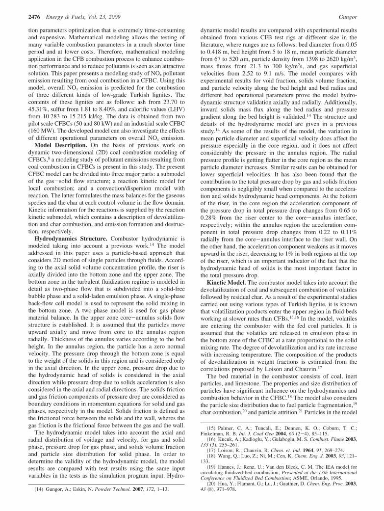
The emission of NOx depends on temperature because theNOx oxidation changes significantly with temperatures.25 The
increase of NOx emissions with combustor temperature isobserved in Figure 2 for 50 kW pilot scale CFBC, whereasbelow 800 °C NOx emissions are rather low. Over 800 °C someincrease in NOx emissions is observed. The carbon contentdepends on temperature and the combustion rate of char, whichcould be determined from the kinetic model of char combustion.With the increase of temperature, the reaction rate constant ofchar combustion increases, which leads to lower char concentra-tion in the combustor and lower CO concentration. The modelCO concentration profile is also shown in Figure 2. Thereduction of NOx emissions is proportional to the presence ofchar particles and CO concentration in the control volume. Dueto the lack of enough char particles and lower CO concentration,the reduction of NOx to N2 decreases. The results of Lin et al.30’sstudy also verify this phenomena. It is clearly seen from Figure2 that both experimental data and model predictions show theclose agreement.
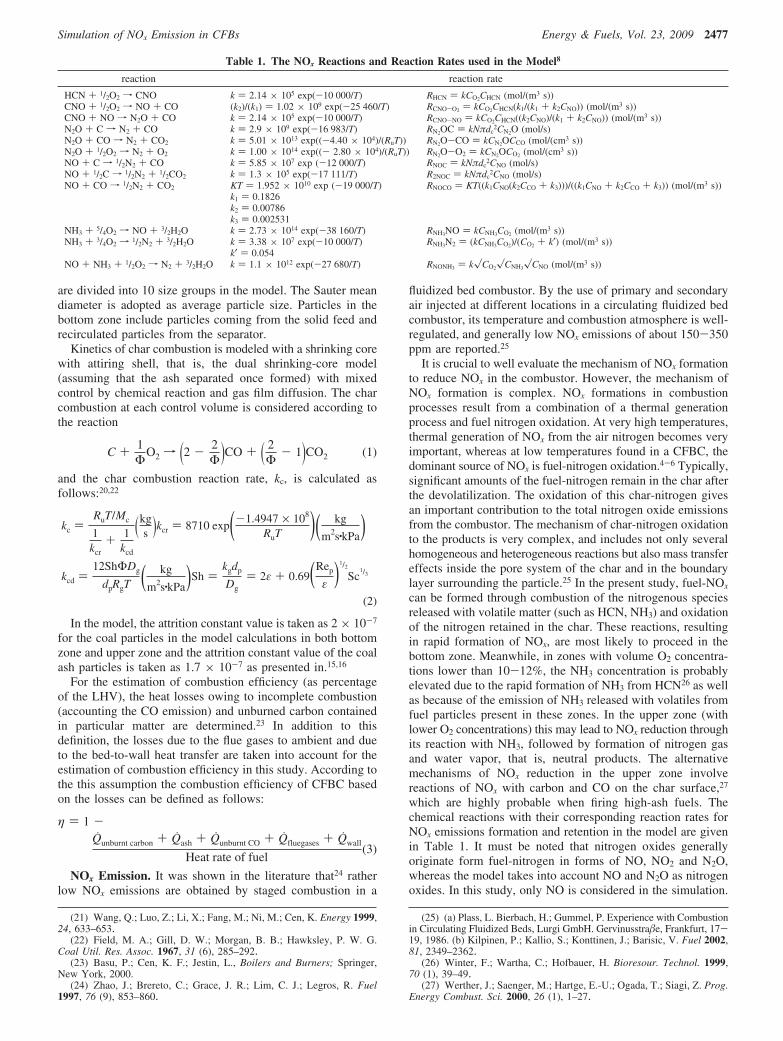
In Figure 3, NOx emissions based on 7% O2 in the flue gasfor 80 kW pilot-scale CFBC are plotted with respect to excessair, which rages between 35 and 80%, where the mean bedtemperature range is 857-768 °C (for 857 °C, the excess air is35%; for 768 °C, the excess air is 80%). The model COconcentration profile is also shown in Figure 3. In Figure 3, theNOx emission decreases with increasing excess air as observedin both experimental data and model predictions. Although theamount of oxygen increases with increasing excess air, decreas-ing bed temperature causes a negative effect on coal combustion
(28) Topal, H. Experimental inVestigation of the hydrodynamic, combus-tion and emission properties of a circulating fluidized bed; Ph.D. Thesis,Gazi University Institute of Science and Technology: Turkey, 1999.
(29) Topal, H.; Atimtay, A. T.; Durmaz, A. Fuel 2004, 82, 1049–1056.(30) Lin, C. H.; Teng, J. T.; Chyang, C. S. Combust. Flame 1997, 110,
163–172.
Table 3. Proximate and Ultimate Analysis of Lignites
Beypazarilignite
Canlignite
Tuncbileklignite
proximate analysis (wt %)moisture 14.30 28.42 7.50ash 35.20 14.34 23.70volatile matter 31.50 29.74 27.50fixed carbon 19.00 27.50 41.30
ultimate analysis (wt %, dry)C 37.20 40.85 59.29H 2.90 4.01 4.61N 1.30 2.25 2.10O 14.90 12.79 11.54S 2.60 8.40 1.81ash 41.10 31.70 20.65LHV (MJ/kg, dry) 10.283 11.704 22.062
Table 4. Operating Parameters of the Experimental DataReferred to in This Study
operatingparameters
50 kWpilot scalecombustor2
80 kWpilot scale
combustor28
160 MWindustrial scale
combustor13
coal feed rate 15.1 kg/h 6-7.7 kg/h 110-120 t/hoperation velocity 1.75 m/s 3.60-9.23 m/s 4-6 m/sbed temperature 850-900 °C 860-900 °C 850-900 °Cprimary/secondary
air ratio2/3 2/3
size of coal feed 0.03-0.90 mm 0.1-9.0 mmmean size of
sorbent feed0.071-0.100 mm 0.1-0.15 mm
Figure 2. Comparison of model NOx emission predictions withexperimental data for 50 kW pilot scale CFBC2 with regard to the meanbed temperature.
Figure 3. Comparison of model NOx emission predictions withexperimental data for 80 kW pilot-scale CFBC28 with regard to theexcess ratio.
Simulation of NOx Emission in CFBs Energy & Fuels, Vol. 23, 2009 2479

efficiency, which results in lower levels of NOx formation.31
Decreasing combustion efficiency also causes higher carboncontent in the combustor. Thus, the reduction rate of NOx
increases. Another explanation of decreasing NOx emission isthe gas dilution caused by increasing excess air. As for COconcentrations, decreasing bed temperature results in the reactionrate of char combustion to decrease and also a decrease of theCO oxidation rate constant, which leads to higher CO emission,which is another reason for lower NOx emission as displayedin Figure 3. This phenomenon is also observed in the studiesof Desroches-Ducarne et al.32
For the 160 MW industrial-scale CFBC, temperature and NOx
emissions response in flue gases simulation and test results atthe riser exit are compared at different coal feed rates, and theresults are presented in Table 5. It is seen that the simulationresults are in good agreement with industrial-scale CFBC dataas well.
Model predictions are in good agreement with both industrialand small-scale CFBCs, which is an indication that the modelis flexible enough to be used in different CFB applications andsimulates under a wide range of operating conditions such ascoal type, combustor temperature, and excess air ratio. More-over, both experimental data and model predictions show theclose agreement and have low and acceptable levels of NOx
emissions.Effects of Operational Parameters. In the present study,
the variations of the overall NOx emission under differentoperational conditions such as excess air (20-100%), bedoperational velocity (4.15-6.50 m/s), and coal particle diameter(540-852 µm) are analyzed for the 80 kW pilot-scale CFBCconditions with the developed and validated 2D model withrespect to these emissions.
Excess air is one of the operating variables affecting boththermal and environmental performances of a CFB. Ingeneral, the carbon combustion efficiency increases withincreasing excess air. This indicates that air staging couldimprove combustion. An increase of excess air gives anincrease in the mean oxygen concentration in the bed. Thiscauses the combustion rate of char to increase by the amountof oxygen present, thus increasing the carbon combustionefficiency. Since the size of the CFBC considered in thisstudy is quite small, a decrease of the combustion efficiencyis observed due to the combustion losses increase withincreasing excess air. Excess air affects combustion efficiencyin two ways: one is due to higher heat losses with increasingflue gas flow rates to the ambient. As expected, decreasing
the temperature decreases the carbon combustion efficiencydue to the decrease in the reaction rates. The other one isbed temperature decreases as the excess air increases, and itaffects the carbon combustion efficiency due to decreases inthe reaction rates and as a result higher carbon content inthe mass discharged from the combustor. This phenomenonis also observed in the study of Bhatt.33 As mentioned above,decreasing bed temperature generates a decrease of the COoxidation rate constant.
The reduction of NOx emissions is proportional to thepresence of char particles and CO concentration in the controlvolume. Higher carbon content and CO concentration lead tolower NOx emissions as clearly seen in Figure 4. Anotherexplanation of decreasing NOx emission is the gas dilutioncaused by increasing excess air, which is also observed in thestudies of Liu and Gibbs34 and Xie et al.35 A smaller mean sizeof char in the combustor will result in a lower emission of NOx
if other parameters are kept unchanged,36 as clearly seen fromFigures 4 and 5.
The bed operational velocity in the combustor is one of thebasic design variables of the process. The reason is that withthe increase of bed operating velocity the hydrodynamiccondition of the combustor changes. The bed operationalvelocity increases circulation flow rates of solids and results ina decrease of the mean residence time of char particles in thecombustor. This situation causes insufficient residence time forcomplete combustion and, consequently, CO emission increasesand the mean bed temperature decreases. On the other hand,suspension density in the bed decreases with increasing super-ficial velocity, which results in lower level of char particles inthe control volume. Therefore, NOx emissions increase with thesuperficial velocity of the combustor (Figure 5). This phenom-enon is also observed in the study of Scala and Salatino.37 Thehigh fuel-N contents of the large size of particles causes the
(31) Madhiyanon, T.; Lapirattanakun, A.; Sathitruangsak, P.; Sopon-ronnarit, S. Combust. Flame 2006, 146 (1-2), 232–245.
(32) Desroches-Ducarne, E.; Dolignier, J. C.; Marty, E.; Martin, G.;Delfosse, L. Fuel 1998, 77, 1399–1410.
(33) Bhatt, M. S. Energy ConV. Manag. 2007, 48, 2150–2160.(34) Liu, H.; Gibbs, B. M. Fuel 2002, 81, 271–80.(35) Xie, J.; Yang, X.; Zhang, L.; Ding, T.; Song, W.; Lin, W. J. EnV.
Sci. 2007, 19 (1), 109–116.(36) Talukdar, J.; Basu, P. Can. J. Chem. Eng. 1995, 73, 635–643.(37) Scala, F.; Salatino, P. Chem. Eng. Sci. 2002, 57, 1175–96.
Table 5. Comparison of Simulation Results with 160 MW Industrial CFBC Test Results13
T (°C) NOx (ppm)
time (min.) coal feed (t/h) model data error (%) model data error (%)30 119.1 798.50 807.1 1.06 73.425 72.825 0.8260 119.0 798.79 809.1 1.27 72.675 71.925 1.0390 116.9 800.36 812.4 1.48 73.17 74.025 1.14120 116.3 798.59 814.9 2.00 69.39 69.525 0.18150 116.0 798.40 812.3 1.71 76.5225 76.875 0.45180 118.4 798.26 805.5 0.89 74.2125 74.025 0.29210 113.8 804.01 809.3 0.65 74.295 73.65 0.87
Figure 4. Effect of excess air ratio on the overall NOx emission fromthe combustor. Tmean ) 868 °C (for the excess air ) 0%); Tmean ) 756°C (for the excess air ) 100%).
2480 Energy & Fuels, Vol. 23, 2009 Gungor
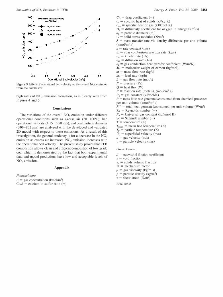
high rates of NOx emission formation, as is clearly seen fromFigures 4 and 5.
Conclusions
The variations of the overall NOx emission under differentoperational conditions such as excess air (20-100%), bedoperational velocity (4.15-6.50 m/s), and coal particle diameter(540-852 µm) are analyzed with the developed and validated2D model with respect to these emissions. As a result of thisinvestigation, the general tendency is for a decrease in the NOx
emission as excess air increases. NOx emission increases withthe operational bed velocity. The present study proves that CFBcombustion allows clean and efficient combustion of low gradecoal which is demonstrated by the fact that both experimentaldata and model predictions have low and acceptable levels ofNOx emission.
Appendix
NomenclatureC ) gas concentration (kmol/m3)Ca/S ) calcium to sulfur ratio (-)
CD ) drag coefficient (-)cp ) specific heat of solids (kJ/kg K)cjp,g ) specific heat of gas (kJ/kmol K)Dg ) diffusivity coefficient for oxygen in nitrogen (m2/s)dp ) particle diameter (m)G ) solid stress modulus (N/m2)J ) mass transfer rate via density difference per unit volume(kmol/m3 s)k ) rate constant (m/s)kc ) char combustion reaction rate (kg/s)kcr ) kinetic rate (1/s)kcd ) diffusion rate (1/s)kg ) gas conduction heat transfer coefficient (W/m/K)Mc ) molecular weight of carbon (kg/mol)m ) mass flow rate (kg/s)mf ) feed rate (kg/h)n ) gas flow rate (mol/s)P ) pressure (Pa)Q ) heat flux (W)R ) reaction rate (mol/ s), (mol/cm3 s)Rg ) gas constant (kJ/mol/K)R ) mass flow rate generated/consumed from chemical processesper unit volume (kmol/m3 s)R′′′ ) total heat generated/consumed per unit volume (W/m3)Re ) Reynolds number (-)Ru ) Universal gas constant (kJ/kmol K)Sc ) Schmidt number (-)T ) temperature (K)Tmean ) mean bed temperature (K)Tp ) particle temperature (K)U0 ) superficial velocity (m/s)u ) gas velocity (m/s)V ) particle velocity (m/s)
Greek Letters
� ) gas-solid friction coefficientε ) void fractionεp ) solids volume fractionΦ ) mechanism factorµ ) gas viscosity (kg/m s)F ) particle density (kg/m3)τ ) shear stress (N/m2)
EF8010838
Figure 5. Effect of operational bed velocity on the overall NOx emissionfrom the combustor.
Simulation of NOx Emission in CFBs Energy & Fuels, Vol. 23, 2009 2481