Embed Size (px)
DESCRIPTION
Simulation of Magnetically Confined Plasma for HDD Etch Applications, DTR Magnetic Media
Citation preview
Think Lean – Create Value
Computational Optimization of
Magnetically Enhanced CCP Plasma
Uniformity for Disk Etch Applications
Vladimir Kudriavtsev, Wenli Collison
Huong Nguyen, Pat Ward, Michael Barnes,
Mark Kushner
62nd Annual Gaseous Electronics Plasma Conference
GEC 09 - American Physical Society
October, 2009

Think Lean – Create Value
Summary

Think Lean – Create Value
Magnetic Field Line Uniformity Analogy
-improve magnetic line angle uniformity and desired cross-section and you will improveplasma uniformity
-best way to do it to increase magnet to substrate distance, however that weakens corresponding magnetic field
Think Lean – Create Value
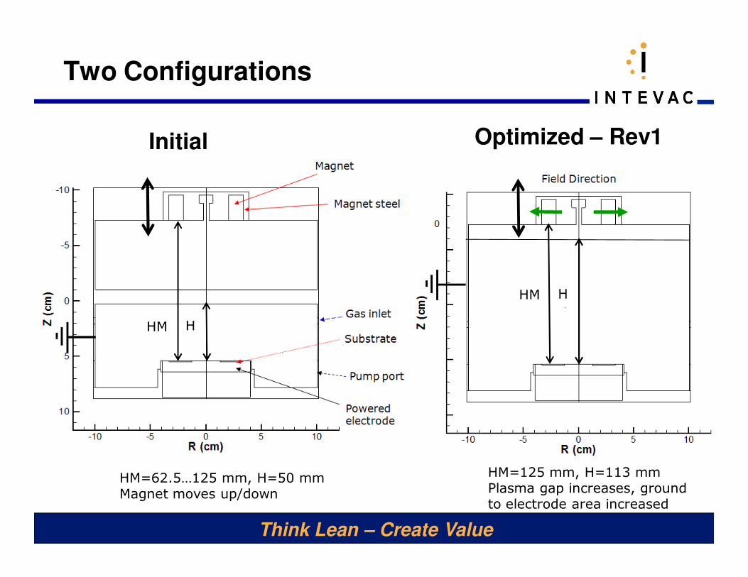
Two Configurations
Initial Optimized – Rev1
HM H
HM H
HM=62.5…125 mm, H=50 mmMagnet moves up/down
HM=125 mm, H=113 mmPlasma gap increases, ground to electrode area increased
Think Lean – Create Value
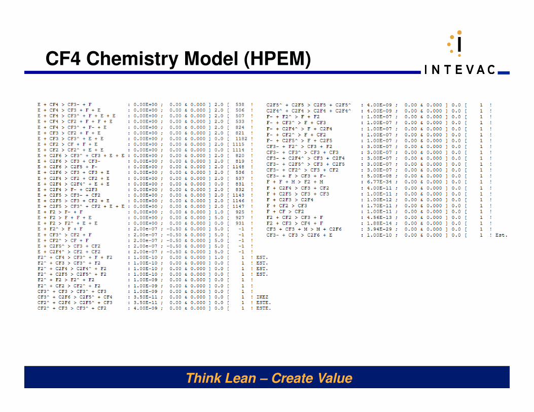
CF4 Chemistry Model (HPEM)
Think Lean – Create Value
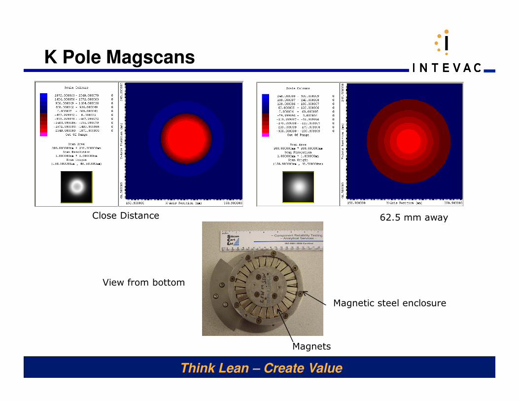
K Pole Magscans
Close Distance 62.5 mm away
View from bottom
Magnetic steel enclosure
Magnets
Think Lean – Create Value
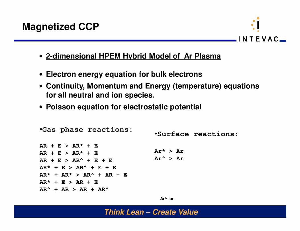
Magnetized CCP
• 2-dimensional HPEM Hybrid Model of Ar Plasma
• Electron energy equation for bulk electrons
• Continuity, Momentum and Energy (temperature) equations
for all neutral and ion species.
• Poisson equation for electrostatic potential
•Gas phase reactions:
AR + E > AR* + E
AR + E > AR* + E
AR + E > AR^ + E + E
AR* + E > AR^ + E + E
AR* + AR* > AR^ + AR + E
AR* + E > AR + E
AR^ + AR > AR + AR^
•Surface reactions:
Ar* > Ar
Ar^ > Ar
Ar^-ion
Think Lean – Create Value
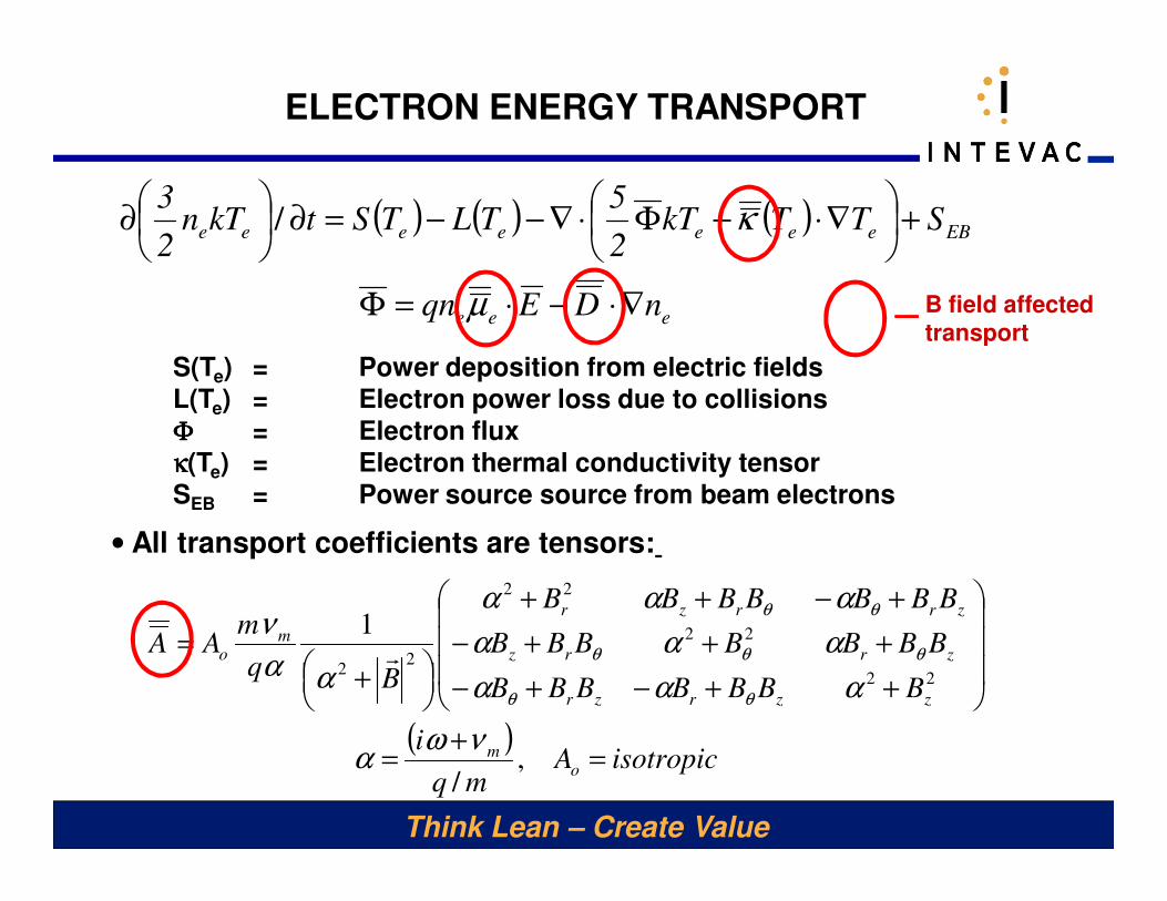
ELECTRON ENERGY TRANSPORT
S(Te) = Power deposition from electric fields
L(Te) = Electron power loss due to collisions
ΦΦΦΦ = Electron flux
κκκκ(Te) = Electron thermal conductivity tensor
SEB = Power source source from beam electrons
( ) ( ) ( )
eee
EBeeeeeee
nDEqn
STTkT2
5TLTStkTn
2
3
∇⋅−⋅=Φ
+
∇⋅−Φ⋅∇−−=∂
∂
µ
κ/
( )isotropicA
mq
i
BBBBBBB
BBBBBBB
BBBBBBB
Bq
mAA
om
zzrzr
zrrz
zrrzr
mo
=+
=
++−+−
+++−
+−++
+
=
,/
1
22
22
22
22
νωα
ααα
ααα
ααα
αα
ν
θθ
θθθ
θθ
r
• All transport coefficients are tensors:
B field affected transport
Think Lean – Create Value
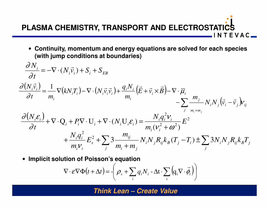
PLASMA CHEMISTRY, TRANSPORT AND ELECTROSTATICS
• Continuity, momentum and energy equations are solved for each species
(with jump conditions at boundaries)
• Implicit solution of Poisson’s equation
( ) ( )
⋅∇⋅∆+=∆+Φ∇⋅∇ ∑∑
i
iqt-- i
i
iis Nqtt φρεr
EBiiii SSvN
t
N++⋅−∇= )(
r
∂
∂
( ) ( ) ( ) ( ) ii
i
iiiiiii
i
ii BvEm
NqvvNTkN
mt
vNµ
∂
∂⋅∇−×++⋅∇−∇=
rrrrrr
1
( ) ijjij
j
i
mm
jvvNN
m
ji
νrr
−−∑+
( ) 2
22
2
)()U(UQ E
m
qNNP
t
N
ii
iiiiiiiii
ii
ων
νε
∂
ε∂
+=⋅∇+⋅∇+⋅∇+
∑∑ ±−+
++j
jBijji
j
ijBijji
ji
ij
s
ii
ii TkRNNTTkRNNmm
mE
m
qN3)(32
2
ν
Think Lean – Create Value
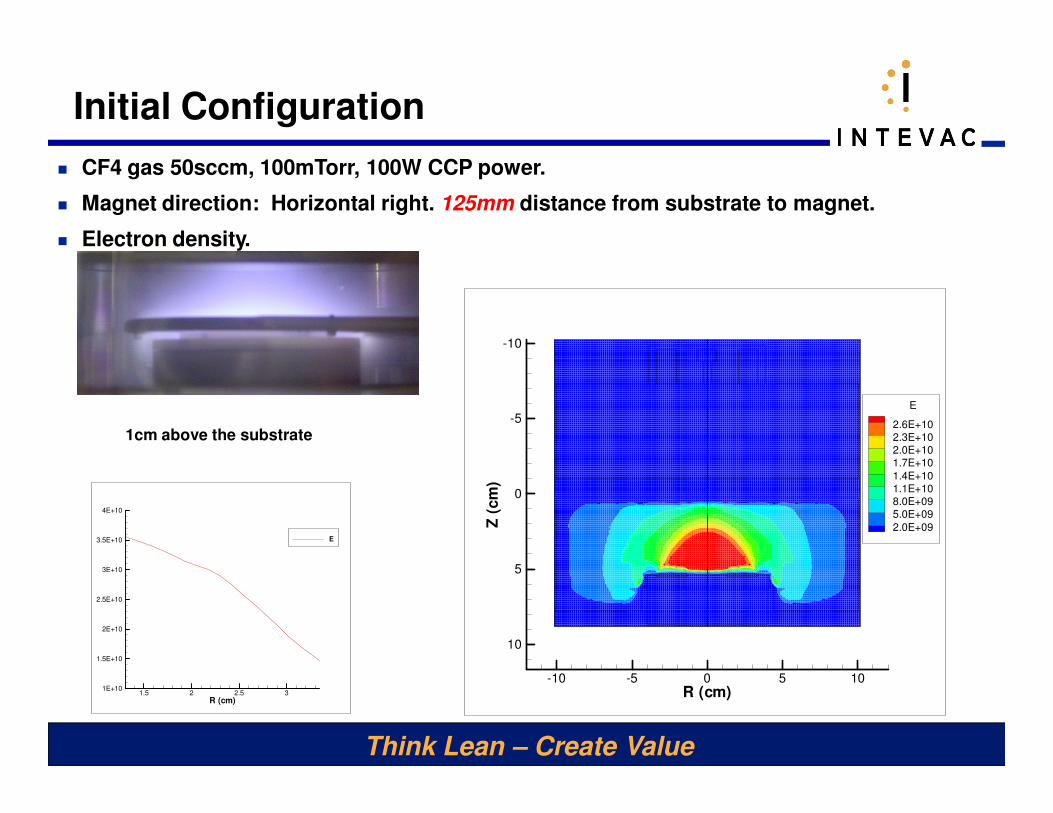
Initial Configuration
� CF4 gas 50sccm, 100mTorr, 100W CCP power.
� Magnet direction: Horizontal right. 125mm distance from substrate to magnet.
� Electron density.
R (cm)
Z(c
m)
-10 -5 0 5 10
-10
-5
0
5
10
E
2.6E+102.3E+102.0E+101.7E+10
1.4E+101.1E+108.0E+095.0E+09
2.0E+09
R (cm)
E
1.5 2 2.5 31E+10
1.5E+10
2E+10
2.5E+10
3E+10
3.5E+10
4E+10
E
1cm above the substrate
Think Lean – Create Value
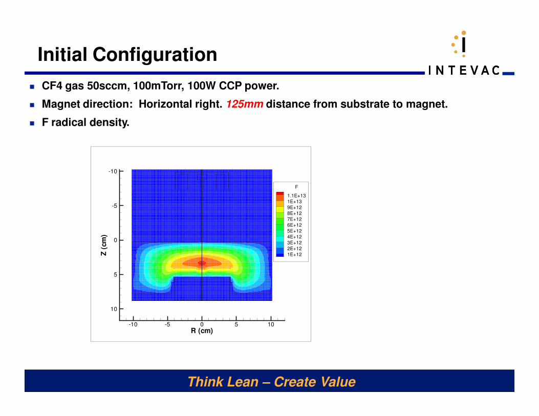
Initial Configuration
� CF4 gas 50sccm, 100mTorr, 100W CCP power.
� Magnet direction: Horizontal right. 125mm distance from substrate to magnet.
� F radical density.
R (cm)
Z(c
m)
-10 -5 0 5 10
-10
-5
0
5
10
F
1.1E+13
1E+13
9E+12
8E+12
7E+12
6E+12
5E+12
4E+12
3E+12
2E+12
1E+12

Think Lean – Create Value
Initial Configuration
� CF4 gas 50sccm, 100mTorr, 100W CCP power.
� Magnet direction: Horizontal right. 125mm distance from substrate to magnet.
� Plasma potential.
R (cm)
Z(c
m)
-10 -5 0 5 10
-10
-5
0
5
10
P-POT
60
46
31
17
3
-11
-26
-40
Think Lean – Create Value
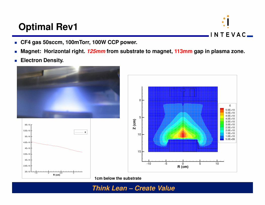
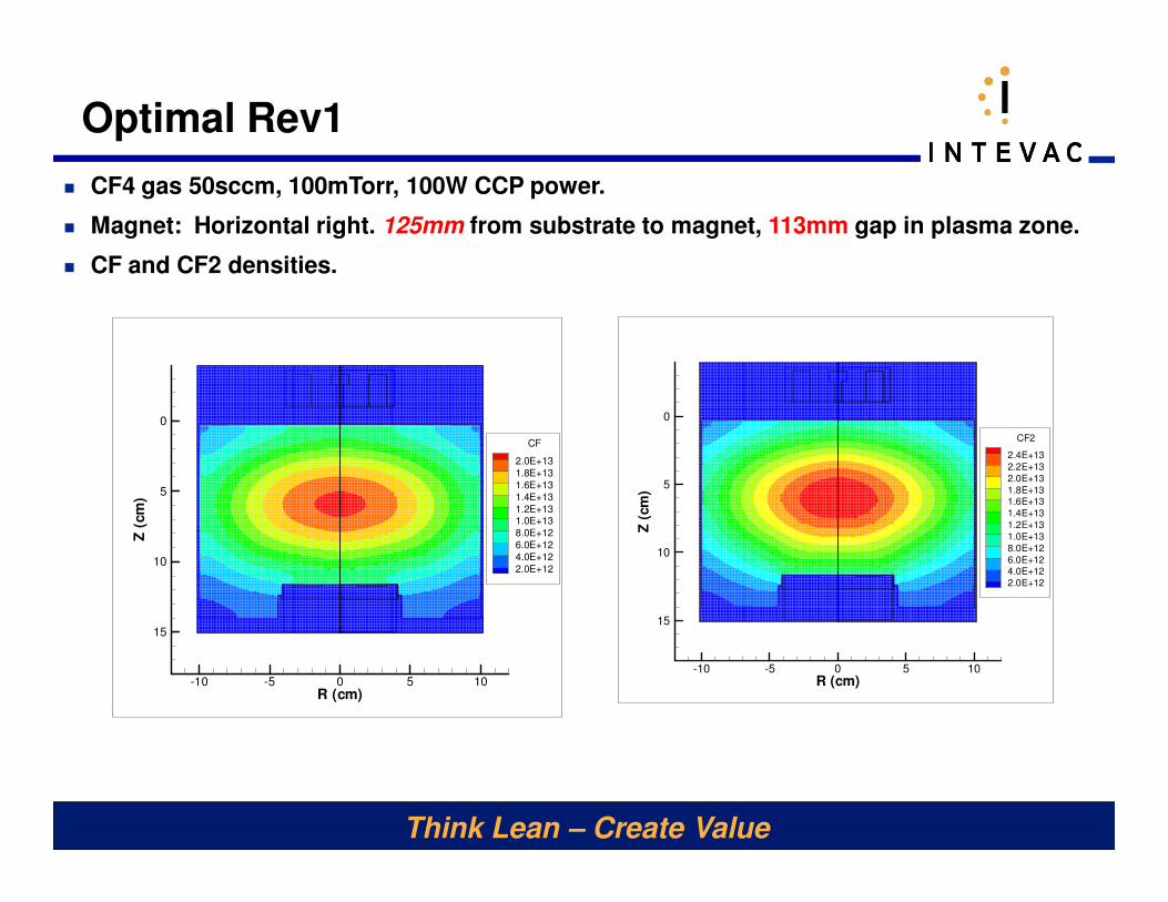
Optimal Rev1
� CF4 gas 50sccm, 100mTorr, 100W CCP power.
� Magnet: Horizontal right. 125mm from substrate to magnet, 113mm gap in plasma zone.
� Electron Density.
R (cm)
Z(c
m)
-10 -5 0 5 10
0
5
10
15
E
5.5E+105.0E+10
4.5E+104.0E+103.5E+103.0E+10
2.5E+102.0E+101.5E+101.0E+10
5.0E+09
1cm below the substrateR (cm)
E
1.5 2 2.5 32E+10
2.5E+10
3E+10
3.5E+10
4E+10
4.5E+10
5E+10
5.5E+10
6E+10
E
Think Lean – Create Value
Optimal Rev1
� CF4 gas 50sccm, 100mTorr, 100W CCP power.
� Magnet: Horizontal right. 125mm from substrate to magnet, 113mm gap in plasma zone.
� CF and CF2 densities.
R (cm)
Z(c
m)
-10 -5 0 5 10
0
5
10
15
CF2
2.4E+13
2.2E+13
2.0E+13
1.8E+131.6E+13
1.4E+13
1.2E+13
1.0E+13
8.0E+12
6.0E+124.0E+12
2.0E+12
R (cm)
Z(c
m)
-10 -5 0 5 10
0
5
10
15
CF
2.0E+13
1.8E+13
1.6E+13
1.4E+13
1.2E+131.0E+13
8.0E+12
6.0E+12
4.0E+12
2.0E+12
Think Lean – Create Value
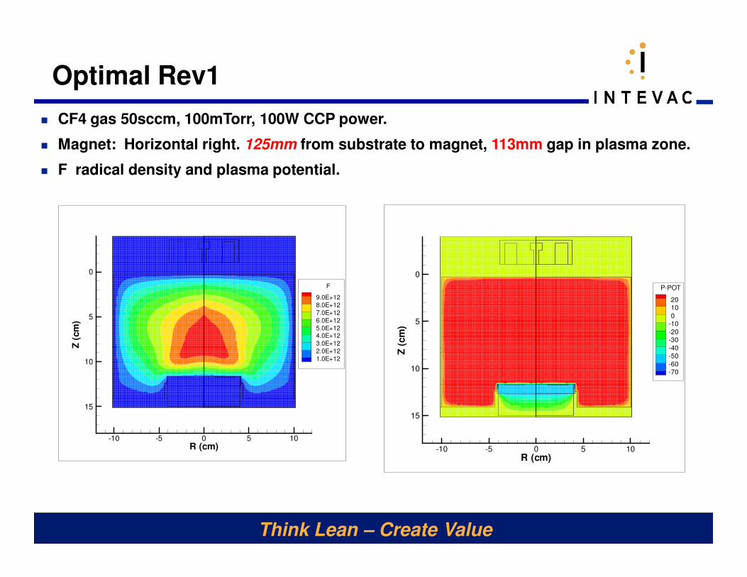
Optimal Rev1
� CF4 gas 50sccm, 100mTorr, 100W CCP power.
� Magnet: Horizontal right. 125mm from substrate to magnet, 113mm gap in plasma zone.
� F radical density and plasma potential.
R (cm)
Z(c
m)
-10 -5 0 5 10
0
5
10
15
F
9.0E+12
8.0E+12
7.0E+12
6.0E+12
5.0E+124.0E+12
3.0E+12
2.0E+12
1.0E+12
R (cm)
Z(c
m)
-10 -5 0 5 10
0
5
10
15
P-POT
2010
0-10
-20-30
-40-50
-60-70
Think Lean – Create Value
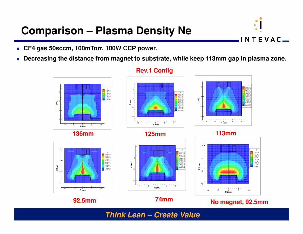
Comparison – Plasma Density Ne
� CF4 gas 50sccm, 100mTorr, 100W CCP power.
� Decreasing the distance from magnet to substrate, while keep 113mm gap in plasma zone.
R (cm)
Z(c
m)
-10 -5 0 5 10
0
5
10
15
E
5.5E+105.0E+10
4.5E+10
4.0E+103.5E+10
3.0E+102.5E+10
2.0E+10
1.5E+101.0E+10
5.0E+09
125mm
R (cm)
Z(c
m)
-10 -5 0 5 10
0
5
10
15
E
5.50E+105.08E+10
4.67E+104.25E+10
3.83E+103.42E+10
3.00E+102.58E+102.17E+10
1.75E+101.33E+10
9.17E+095.00E+09
74mm92.5mm
113mm
R (cm)
Z(c
m)
-10 -5 0 5 10
0
5
10
15
E
5.50E+10
5.00E+104.50E+10
4.00E+10
3.50E+103.00E+10
2.50E+10
2.00E+10
1.50E+101.00E+10
5.00E+09
R (cm)
Z(c
m)
-10 -5 0 5 10
0
5
10
15
E
5.50E+10
5.05E+10
4.59E+104.14E+10
3.68E+10
3.23E+10
2.77E+102.32E+10
1.86E+10
1.41E+10
9.55E+095.00E+09
R (cm)
Z(c
m)
-10 -5 0 5 10
0
5
10
15
E
5.5E+10
4.7E+10
3.8E+10
3.0E+10
2.2E+101.3E+10
5.0E+09
136mm
R (cm)
Z(c
m)
-10 -5 0 5 10
0
5
10
15
E
4.5E+10
4E+10
3.5E+10
3E+10
2.5E+10
2E+10
1.5E+10
1E+10
5E+09
No magnet, 92.5mm
Rev.1 Config
Think Lean – Create Value
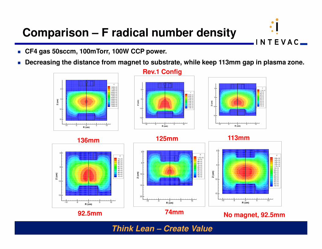
Comparison – F radical number density
� CF4 gas 50sccm, 100mTorr, 100W CCP power.
� Decreasing the distance from magnet to substrate, while keep 113mm gap in plasma zone.
125mm
74mm92.5mm
113mm136mm
No magnet, 92.5mm
Rev.1 Config
R (cm)
Z(c
m)
-10 -5 0 5 10
0
5
10
15
F
1.5E+13
1.4E+13
1.3E+13
1.2E+13
1.1E+13
1E+13
9E+12
8E+12
7E+12
6E+12
5E+12
4E+123E+12
2E+12
1E+12
R (cm)
Z(c
m)
-10 -5 0 5 10
0
5
10
15
F
1.20E+13
1.10E+131.00E+13
9.00E+12
8.00E+127.00E+12
6.00E+12
5.00E+124.00E+12
3.00E+12
2.00E+121.00E+12
R (cm)
Z(c
m)
-10 -5 0 5 10
0
5
10
15
F
9.0E+12
8.0E+127.0E+126.0E+12
5.0E+124.0E+12
3.0E+122.0E+121.0E+12
R (cm)
Z(c
m)
-10 -5 0 5 10
0
5
10
15
F
1.1E+13
1E+13
9E+12
8E+12
7E+126E+12
5E+12
4E+12
3E+12
2E+12
1E+12
R (cm)
Z(c
m)
-10 -5 0 5 10
0
5
10
15
F
1E+13
9E+12
8E+127E+12
6E+125E+12
4E+12
3E+122E+12
1E+12
R (cm)
Z(c
m)
-10 -5 0 5 10
0
5
10
15
20
F
1.1E+131E+13
9E+128E+12
7E+126E+12
5E+124E+12
3E+122E+12
1E+12
Think Lean – Create Value
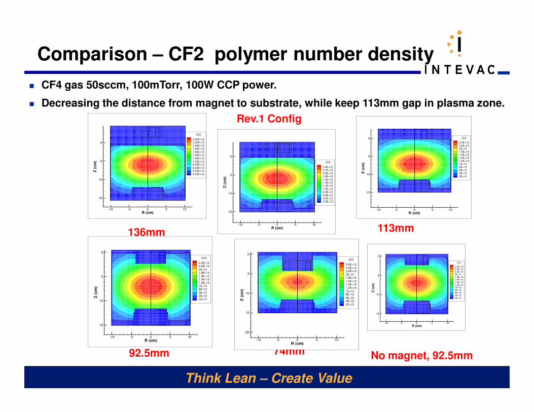
Comparison – CF2 polymer number density
� CF4 gas 50sccm, 100mTorr, 100W CCP power.
� Decreasing the distance from magnet to substrate, while keep 113mm gap in plasma zone.
125mm
74mm92.5mm
113mm136mm
No magnet, 92.5mm
Rev.1 Config
R (cm)
Z(c
m)
-10 -5 0 5 10
0
5
10
15
CF2
2.6E+132.4E+132.2E+132E+131.8E+131.6E+13
1.4E+131.2E+131E+138E+126E+124E+12
2E+12
R (cm)
Z(c
m)
-10 -5 0 5 10
0
5
10
15
20
CF2
2.6E+13
2.4E+132.2E+13
2E+131.8E+13
1.6E+131.4E+13
1.2E+13
1E+138E+12
6E+124E+12
2E+12
R (cm)
Z(c
m)
-10 -5 0 5 10
0
5
10
15
CF2
2.4E+132.2E+13
2E+131.8E+13
1.6E+131.4E+13
1.2E+131E+138E+12
6E+124E+12
2E+12
R (cm)
Z(c
m)
-10 -5 0 5 10
0
5
10
15
CF2
2.4E+13
2.2E+13
2E+13
1.8E+13
1.6E+13
1.4E+13
1.2E+13
1E+13
8E+12
6E+12
4E+12
2E+12
R (cm)Z
(cm
)-10 -5 0 5 10
0
5
10
15
CF2
2.4E+132.2E+13
2.0E+131.8E+13
1.6E+131.4E+131.2E+13
1.0E+138.0E+12
6.0E+124.0E+122.0E+12
R (cm)
Z(c
m)
-10 -5 0 5 10
0
5
10
15
CF2
2.40E+132.20E+13
2.00E+131.80E+13
1.60E+131.40E+13
1.20E+13
1.00E+138.00E+12
6.00E+124.00E+12
2.00E+12
Think Lean – Create Value
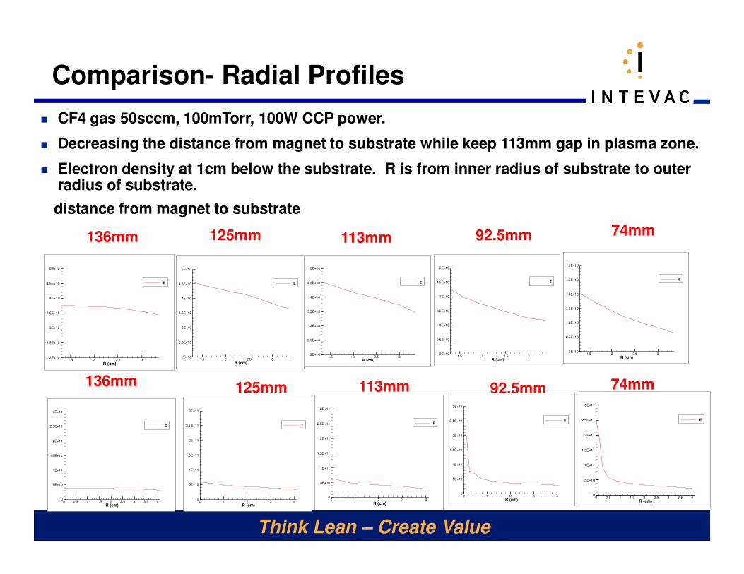
Comparison- Radial Profiles
� CF4 gas 50sccm, 100mTorr, 100W CCP power.
� Decreasing the distance from magnet to substrate while keep 113mm gap in plasma zone.
� Electron density at 1cm below the substrate. R is from inner radius of substrate to outer radius of substrate.
125mm
distance from magnet to substrate
74mm92.5mm113mm
R (cm)
E
1.5 2 2.5 32E+10
2.5E+10
3E+10
3.5E+10
4E+10
4.5E+10
5E+10
E
R (cm)
E
1.5 2 2.5 32E+10
2.5E+10
3E+10
3.5E+10
4E+10
4.5E+10
5E+10
E
R (cm)
E
1.5 2 2.5 32E+10
2.5E+10
3E+10
3.5E+10
4E+10
4.5E+10
5E+10
E
R (cm)
E
1.5 2 2.5 32E+10
2.5E+10
3E+10
3.5E+10
4E+10
4.5E+10
5E+10
E
R (cm)
E
1.5 2 2.5 32E+10
2.5E+10
3E+10
3.5E+10
4E+10
4.5E+10
5E+10
E
136mm
74mm92.5mm113mm
R (cm)
E
0 0.5 1 1.5 2 2.5 3 3.5 40
5E+10
1E+11
1.5E+11
2E+11
2.5E+11
3E+11
E
R (cm)
E
0 1 2 3 40
5E+10
1E+11
1.5E+11
2E+11
2.5E+11
3E+11
E
R (cm)
E
0 1 2 3 40
5E+10
1E+11
1.5E+11
2E+11
2.5E+11
3E+11
E
R (cm)
E
0 1 2 3 40
5E+10
1E+11
1.5E+11
2E+11
2.5E+11
3E+11
E
125mm136mm
R (cm)
E
0 0.5 1 1.5 2 2.5 3 3.5 40
5E+10
1E+11
1.5E+11
2E+11
2.5E+11
3E+11
E
Think Lean – Create Value
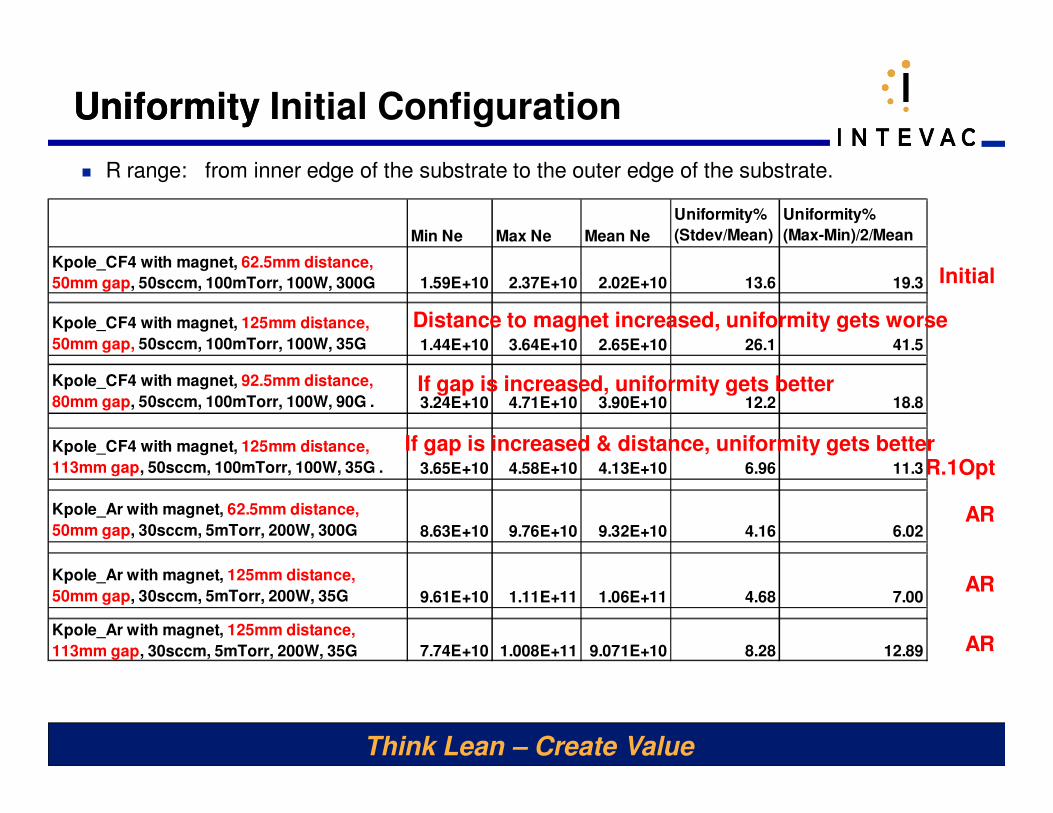
Uniformity Initial Configuration
Initial
AR
Uniformity
� R range: from inner edge of the substrate to the outer edge of the substrate.
Min Ne Max Ne Mean Ne
Uniformity%
(Stdev/Mean)
Uniformity%
(Max-Min)/2/Mean
Kpole_CF4 with magnet, 62.5mm distance,
50mm gap, 50sccm, 100mTorr, 100W, 300G 1.59E+10 2.37E+10 2.02E+10 13.6 19.3
Kpole_CF4 with magnet, 125mm distance,
50mm gap, 50sccm, 100mTorr, 100W, 35G 1.44E+10 3.64E+10 2.65E+10 26.1 41.5
Kpole_CF4 with magnet, 92.5mm distance,
80mm gap, 50sccm, 100mTorr, 100W, 90G . 3.24E+10 4.71E+10 3.90E+10 12.2 18.8
Kpole_CF4 with magnet, 125mm distance,
113mm gap, 50sccm, 100mTorr, 100W, 35G . 3.65E+10 4.58E+10 4.13E+10 6.96 11.3
Kpole_Ar with magnet, 62.5mm distance,
50mm gap, 30sccm, 5mTorr, 200W, 300G 8.63E+10 9.76E+10 9.32E+10 4.16 6.02
Kpole_Ar with magnet, 125mm distance,
50mm gap, 30sccm, 5mTorr, 200W, 35G 9.61E+10 1.11E+11 1.06E+11 4.68 7.00
Kpole_Ar with magnet, 125mm distance,
113mm gap, 30sccm, 5mTorr, 200W, 35G 7.74E+10 1.008E+11 9.071E+10 8.28 12.89
AR
AR
Distance to magnet increased, uniformity gets worse
If gap is increased, uniformity gets better
If gap is increased & distance, uniformity gets betterR.1Opt
Think Lean – Create Value
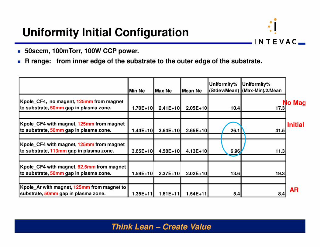
Uniformity Initial Configuration
� R range: from inner edge of the substrate to the outer edge of the substrate.
Initial
AR
Uniformity
Min Ne Max Ne Mean Ne
Uniformity%
(Stdev/Mean)
Uniformity%
(Max-Min)/2/Mean
Kpole_CF4, no magent, 125mm from magnet
to substrate, 50mm gap in plasma zone. 1.70E+10 2.41E+10 2.05E+10 10.4 17.3
Kpole_CF4 with magnet, 125mm from magnet
to substrate, 50mm gap in plasma zone. 1.44E+10 3.64E+10 2.65E+10 26.1 41.5
Kpole_CF4 with magnet, 125mm from magnet
to substrate, 113mm gap in plasma zone. 3.65E+10 4.58E+10 4.13E+10 6.96 11.3
Kpole_CF4 with magnet, 62.5mm from magnet
to substrate, 50mm gap in plasma zone. 1.59E+10 2.37E+10 2.02E+10 13.6 19.3
Kpole_Ar with magnet, 125mm from magnet to
substrate, 50mm gap in plasma zone. 1.35E+11 1.61E+11 1.54E+11 5.4 8.4
� 50sccm, 100mTorr, 100W CCP power.
No Mag
Think Lean – Create Value
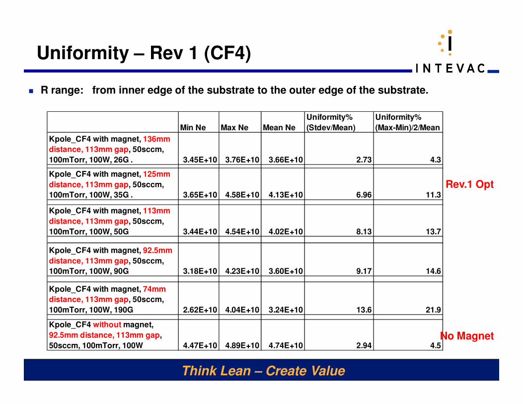
Uniformity – Rev 1 (CF4)
� R range: from inner edge of the substrate to the outer edge of the substrate.
Min Ne Max Ne Mean Ne
Uniformity%
(Stdev/Mean)
Uniformity%
(Max-Min)/2/Mean
Kpole_CF4 with magnet, 136mm
distance, 113mm gap, 50sccm,
100mTorr, 100W, 26G . 3.45E+10 3.76E+10 3.66E+10 2.73 4.3
Kpole_CF4 with magnet, 125mm
distance, 113mm gap, 50sccm,
100mTorr, 100W, 35G . 3.65E+10 4.58E+10 4.13E+10 6.96 11.3
Kpole_CF4 with magnet, 113mm
distance, 113mm gap, 50sccm,
100mTorr, 100W, 50G 3.44E+10 4.54E+10 4.02E+10 8.13 13.7
Kpole_CF4 with magnet, 92.5mm
distance, 113mm gap, 50sccm,
100mTorr, 100W, 90G 3.18E+10 4.23E+10 3.60E+10 9.17 14.6
Kpole_CF4 with magnet, 74mm
distance, 113mm gap, 50sccm,
100mTorr, 100W, 190G 2.62E+10 4.04E+10 3.24E+10 13.6 21.9
Kpole_CF4 without magnet,
92.5mm distance, 113mm gap,
50sccm, 100mTorr, 100W 4.47E+10 4.89E+10 4.74E+10 2.94 4.5
Rev.1 Opt
No Magnet
Think Lean – Create Value
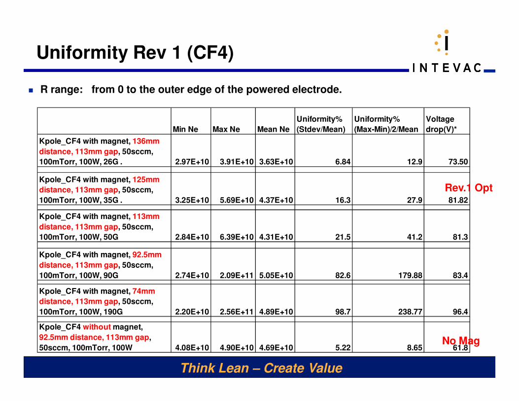
Uniformity Rev 1 (CF4)
� R range: from 0 to the outer edge of the powered electrode.
Min Ne Max Ne Mean Ne
Uniformity%
(Stdev/Mean)
Uniformity%
(Max-Min)/2/Mean
Voltage
drop(V)*
Kpole_CF4 with magnet, 136mm
distance, 113mm gap, 50sccm,
100mTorr, 100W, 26G . 2.97E+10 3.91E+10 3.63E+10 6.84 12.9 73.50
Kpole_CF4 with magnet, 125mm
distance, 113mm gap, 50sccm,
100mTorr, 100W, 35G . 3.25E+10 5.69E+10 4.37E+10 16.3 27.9 81.82
Kpole_CF4 with magnet, 113mm
distance, 113mm gap, 50sccm,
100mTorr, 100W, 50G 2.84E+10 6.39E+10 4.31E+10 21.5 41.2 81.3
Kpole_CF4 with magnet, 92.5mm
distance, 113mm gap, 50sccm,
100mTorr, 100W, 90G 2.74E+10 2.09E+11 5.05E+10 82.6 179.88 83.4
Kpole_CF4 with magnet, 74mm
distance, 113mm gap, 50sccm,
100mTorr, 100W, 190G 2.20E+10 2.56E+11 4.89E+10 98.7 238.77 96.4
Kpole_CF4 without magnet,
92.5mm distance, 113mm gap,
50sccm, 100mTorr, 100W 4.08E+10 4.90E+10 4.69E+10 5.22 8.65 61.8
Rev.1 Opt
No Mag
Think Lean – Create Value
� Plasma uniformity improves with increase in plasma gap
(chamber height) while keeping substrate to magnet
distance constant
� Plasma uniformity improves as magnet is moved away from
the substrate (for fixed chamber dimensions)
� Plasma uniformity without magnetic field enhancement is
higher
� Simultaneous increase in plasma chamber height (plasma
volume, ground area) with increase in substrate to magnet
distance produces sharp improvement in plasma uniformity
Summary
Think Lean – Create Value
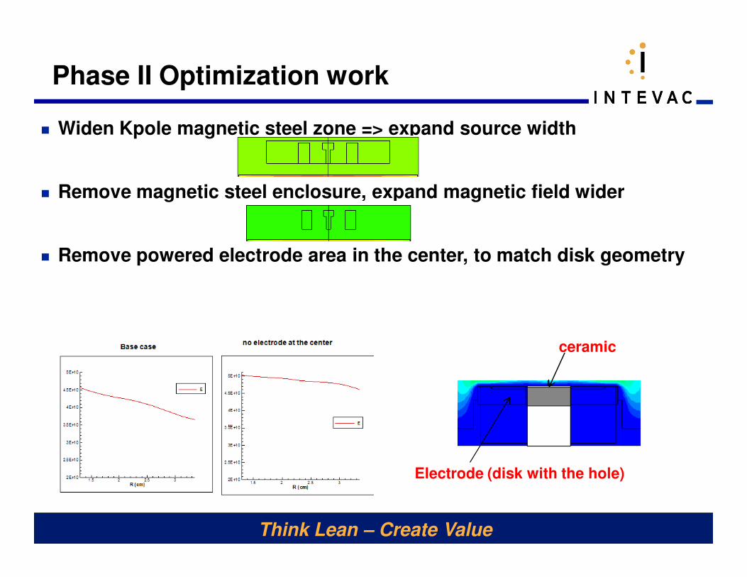
Phase II Optimization work
� Widen Kpole magnetic steel zone => expand source width
� Remove magnetic steel enclosure, expand magnetic field wider
� Remove powered electrode area in the center, to match disk geometry
Electrode (disk with the hole)
ceramic
Think Lean – Create Value
Rev.1 Opt
++
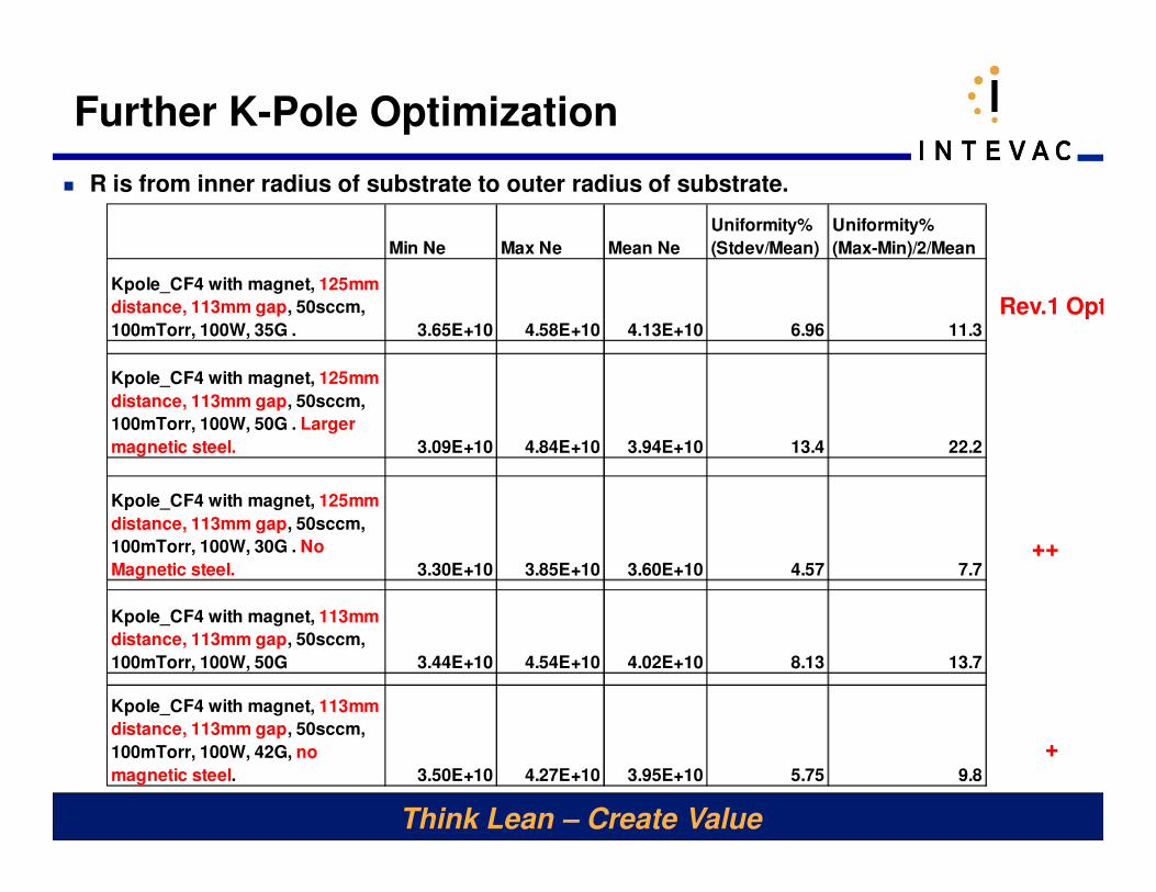
Further K-Pole Optimization
� R is from inner radius of substrate to outer radius of substrate.
Min Ne Max Ne Mean Ne
Uniformity%
(Stdev/Mean)
Uniformity%
(Max-Min)/2/Mean
Kpole_CF4 with magnet, 125mm
distance, 113mm gap, 50sccm,
100mTorr, 100W, 35G . 3.65E+10 4.58E+10 4.13E+10 6.96 11.3
Kpole_CF4 with magnet, 125mm
distance, 113mm gap, 50sccm,
100mTorr, 100W, 50G . Larger
magnetic steel. 3.09E+10 4.84E+10 3.94E+10 13.4 22.2
Kpole_CF4 with magnet, 125mm
distance, 113mm gap, 50sccm,
100mTorr, 100W, 30G . No
Magnetic steel. 3.30E+10 3.85E+10 3.60E+10 4.57 7.7
Kpole_CF4 with magnet, 113mm
distance, 113mm gap, 50sccm,
100mTorr, 100W, 50G 3.44E+10 4.54E+10 4.02E+10 8.13 13.7
Kpole_CF4 with magnet, 113mm
distance, 113mm gap, 50sccm,
100mTorr, 100W, 42G, no
magnetic steel. 3.50E+10 4.27E+10 3.95E+10 5.75 9.8
+
Think Lean – Create Value
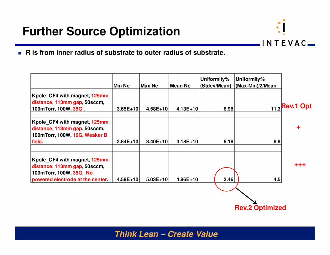
Rev.1 Opt
Min Ne Max Ne Mean Ne
Uniformity%
(Stdev/Mean)
Uniformity%
(Max-Min)/2/Mean
Kpole_CF4 with magnet, 125mm
distance, 113mm gap, 50sccm,
100mTorr, 100W, 35G . 3.65E+10 4.58E+10 4.13E+10 6.96 11.3
Kpole_CF4 with magnet, 125mm
distance, 113mm gap, 50sccm,
100mTorr, 100W, 16G. Weaker B
field. 2.84E+10 3.40E+10 3.18E+10 6.18 8.9
Kpole_CF4 with magnet, 125mm
distance, 113mm gap, 50sccm,
100mTorr, 100W, 35G. No
powered electrode at the center. 4.59E+10 5.03E+10 4.86E+10 2.46 4.5
+
+++
� R is from inner radius of substrate to outer radius of substrate.
Further Source Optimization
Rev.2 Optimized
Think Lean – Create Value
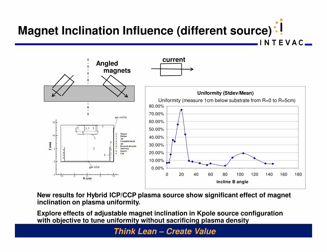
Angled magnets
Magnet Inclination Influence (different source)
current
Uniformity (Stdev/Mean)
0.00%
10.00%
20.00%
30.00%
40.00%
50.00%
60.00%
70.00%
80.00%
0 20 40 60 80 100 120 140 160 180
incline B angle
Uniformity (measure 1cm below substrate from R=0 to R=5cm)
New results for Hybrid ICP/CCP plasma source show significant effect of magnet inclination on plasma uniformity.
Explore effects of adjustable magnet inclination in Kpole source configuration with objective to tune uniformity without sacrificing plasma density

Think Lean – Create Value
Conclusions
� Computational optimization of magnetically enhanced CCP plasma source was conducted, leading to progressive improvement of the source design, with plasma uniformity reduced from 26% down to 2.5%
� Two conceptual source chamber layouts were considered, with second being clearly more beneficial. This layout has increased plasma gap and ratio of ground area to electrode area and considerably weaker magnetic field near substrate.
� Further promise is shown due to electrode modification (removing electrode material in the center) and in adaptive adjustment of Kpole magnet angles (currently angle is zero).
Think Lean – Create Value
Supplemental Materials
Ar Plasma Results
Think Lean – Create Value
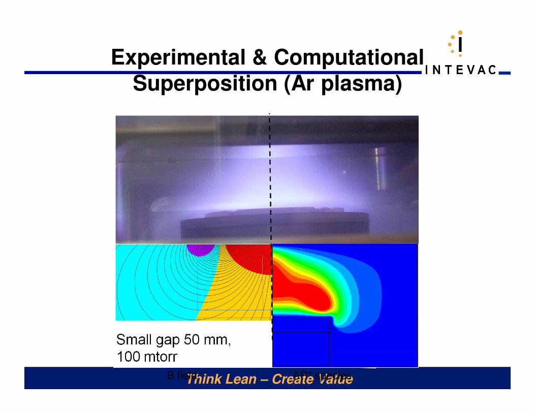
Experimental & Computational
Superposition (Ar plasma)
AR* speciesB field
Think Lean – Create Value
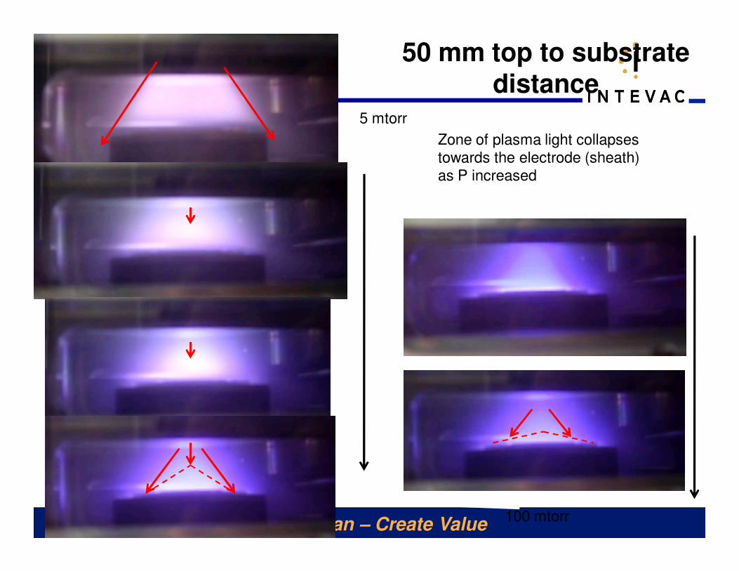
50 mm top to substrate distance
5 mtorr
100 mtorr
Zone of plasma light collapses towards the electrode (sheath) as P increased
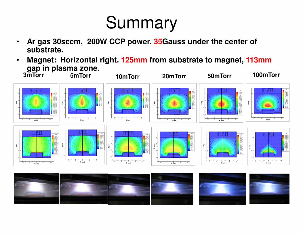
Summary• Ar gas 30sccm, 200W CCP power. 35Gauss under the center of
substrate.
• Magnet: Horizontal right. 125mm from substrate to magnet, 113mmgap in plasma zone.
5mTorr 100mTorr
R (cm)
Z(c
m)
-10 -5 0 5 10
0
5
10
15
E
2.2E+11
2E+11
1.8E+111.6E+11
1.4E+11
1.2E+11
1E+118E+10
6E+10
4E+102E+10
R (cm)
Z(c
m)
-10 -5 0 5 10
0
5
10
15
E
3E+11
2.8E+112.6E+11
2.4E+112.2E+11
2E+11
1.8E+111.6E+11
1.4E+111.2E+11
1E+118E+10
6E+10
4E+102E+10
R (cm)
Z(c
m)
-10 -5 0 5 10
0
5
10
15
AR*
1.60E+121.48E+121.37E+121.25E+121.14E+12
1.02E+129.08E+117.92E+116.77E+115.62E+114.46E+113.31E+11
2.15E+111.00E+11
R (cm)
Z(c
m)
-10 -5 0 5 10
0
5
10
15
AR*
1.00E+12
9.18E+11
8.36E+11
7.55E+116.73E+11
5.91E+11
5.09E+11
4.27E+11
3.45E+11
2.64E+11
1.82E+11
1.00E+11
R (cm)
Z(c
m)
-10 -5 0 5 10
0
5
10
15
E
3E+11
2.8E+11
2.6E+11
2.4E+11
2.2E+11
2E+11
1.8E+11
1.6E+111.4E+11
1.2E+11
1E+11
8E+10
6E+10
4E+10
2E+10
20mTorr
R (cm)
Z(c
m)
-10 -5 0 5 10
0
5
10
15
AR*
7E+11
6.5E+11
6E+115.5E+11
5E+11
4.5E+114E+11
3.5E+113E+11
2.5E+11
2E+111.5E+11
1E+11
5E+10
R (cm)
Z(c
m)
-10 -5 0 5 10
0
5
10
15
E
3.8E+11
3.6E+11
3.4E+11
3.2E+11
3E+112.8E+11
2.6E+11
2.4E+11
2.2E+11
2E+111.8E+11
1.6E+11
1.4E+11
1.2E+11
1E+118E+10
6E+10
4E+10
2E+10
50mTorr
R (cm)
Z(c
m)
-10 -5 0 5 10
0
5
10
15
AR*
8E+11
7.5E+117E+11
6.5E+116E+11
5.5E+115E+11
4.5E+114E+113.5E+11
3E+112.5E+11
2E+111.5E+11
1E+115E+10
3mTorr 10mTorr
R (cm)
Z(c
m)
-10 -5 0 5 10
0
5
10
15
E
2.00E+11
1.89E+11
1.78E+11
1.66E+11
1.55E+111.44E+11
1.33E+11
1.22E+11
1.11E+11
9.94E+108.82E+10
7.71E+10
6.59E+10
5.47E+10
4.35E+10
3.24E+102.12E+10
1.00E+10
R (cm)
Z(c
m)
-10 -5 0 5 10
0
5
10
15
AR*
7.50E+117.00E+116.50E+116.00E+115.50E+11
5.00E+114.50E+114.00E+113.50E+113.00E+112.50E+11
2.00E+111.50E+111.00E+115.00E+10
R (cm)
Z(c
m)
-10-50510
0
5
10
15
E
2.6E+11
2.4E+11
2.2E+112E+11
1.8E+11
1.6E+111.4E+11
1.2E+11
1E+118E+10
6E+10
4E+102E+10
R (cm)
Z(c
m)
-10-50510
0
5
10
15
AR*
7.5E+11
7E+116.5E+11
6E+11
5.5E+11
5E+114.5E+11
4E+11
3.5E+113E+11
2.5E+11
2E+11
1.5E+111E+11
5E+10
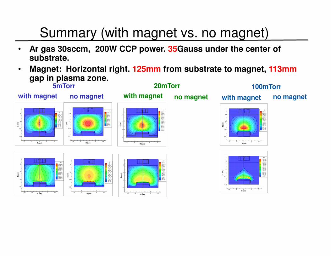
Summary (with magnet vs. no magnet)• Ar gas 30sccm, 200W CCP power. 35Gauss under the center of
substrate.
• Magnet: Horizontal right. 125mm from substrate to magnet, 113mmgap in plasma zone.
5mTorr 100mTorr
R (cm)
Z(c
m)
-10 -5 0 5 10
0
5
10
15
E
2.2E+11
2E+11
1.8E+111.6E+11
1.4E+11
1.2E+11
1E+118E+10
6E+10
4E+102E+10
R (cm)
Z(c
m)
-10 -5 0 5 10
0
5
10
15
E
3E+11
2.8E+112.6E+11
2.4E+112.2E+11
2E+11
1.8E+111.6E+11
1.4E+111.2E+11
1E+118E+10
6E+10
4E+102E+10
R (cm)
Z(c
m)
-10 -5 0 5 10
0
5
10
15
AR*
1.60E+12
1.48E+12
1.37E+121.25E+12
1.14E+12
1.02E+129.08E+11
7.92E+11
6.77E+115.62E+11
4.46E+11
3.31E+112.15E+11
1.00E+11
R (cm)
Z(c
m)
-10 -5 0 5 10
0
5
10
15
AR*
1.00E+12
9.18E+11
8.36E+11
7.55E+116.73E+11
5.91E+11
5.09E+11
4.27E+11
3.45E+11
2.64E+11
1.82E+11
1.00E+11
R (cm)
Z(c
m)
-10 -5 0 5 10
0
5
10
15
E
3E+11
2.8E+11
2.6E+11
2.4E+11
2.2E+11
2E+11
1.8E+11
1.6E+11
1.4E+11
1.2E+11
1E+11
8E+10
6E+10
4E+10
2E+10
20mTorr
R (cm)
Z(c
m)
-10 -5 0 5 10
0
5
10
15
AR*
7E+11
6.5E+11
6E+11
5.5E+11
5E+11
4.5E+11
4E+11
3.5E+11
3E+112.5E+11
2E+11
1.5E+11
1E+11
5E+10
with magnet no magnet with magnet no magnet with magnet no magnet
R (cm)
Z(c
m)
-10 -5 0 5 10
0
5
10
15
E
1.1E+111E+11
9E+10
8E+10
7E+10
6E+105E+10
4E+10
3E+10
2E+10
1E+10
R (cm)
Z(c
m)
-10 -5 0 5 10
0
5
10
15
AR*
7.5E+117E+11
6.5E+11
6E+115.5E+11
5E+114.5E+11
4E+11
3.5E+113E+11
2.5E+112E+11
1.5E+11
1E+115E+10
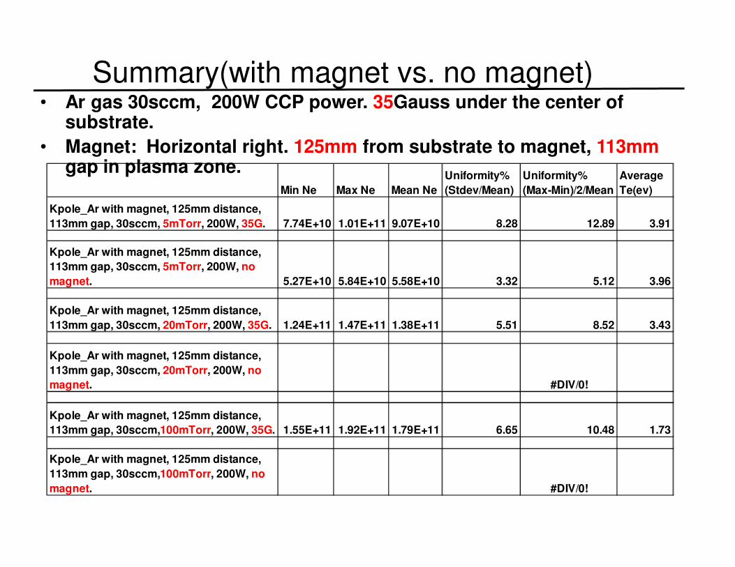
Summary(with magnet vs. no magnet)• Ar gas 30sccm, 200W CCP power. 35Gauss under the center of
substrate.
• Magnet: Horizontal right. 125mm from substrate to magnet, 113mmgap in plasma zone.
Min Ne Max Ne Mean Ne
Uniformity%
(Stdev/Mean)
Uniformity%
(Max-Min)/2/Mean
Average
Te(ev)
Kpole_Ar with magnet, 125mm distance,
113mm gap, 30sccm, 5mTorr, 200W, 35G. 7.74E+10 1.01E+11 9.07E+10 8.28 12.89 3.91
Kpole_Ar with magnet, 125mm distance,
113mm gap, 30sccm, 5mTorr, 200W, no
magnet. 5.27E+10 5.84E+10 5.58E+10 3.32 5.12 3.96
Kpole_Ar with magnet, 125mm distance,
113mm gap, 30sccm, 20mTorr, 200W, 35G. 1.24E+11 1.47E+11 1.38E+11 5.51 8.52 3.43
Kpole_Ar with magnet, 125mm distance,
113mm gap, 30sccm, 20mTorr, 200W, no
magnet. #DIV/0!
Kpole_Ar with magnet, 125mm distance,
113mm gap, 30sccm,100mTorr, 200W, 35G. 1.55E+11 1.92E+11 1.79E+11 6.65 10.48 1.73
Kpole_Ar with magnet, 125mm distance,
113mm gap, 30sccm,100mTorr, 200W, no
magnet. #DIV/0!
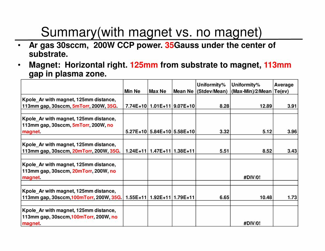
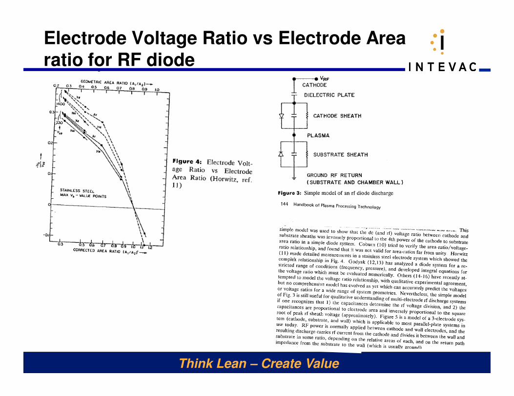
Think Lean – Create Value
Electrode Voltage Ratio vs Electrode Area ratio for RF diode
xxx