Embed Size (px)
Citation preview
Simulation of Internal Wave Wakes and Comparison with Observations
J.K.E. TunaleyLondon Research and Development Corporation,
114 Margaret Anne Drive, Ottawa, Ontario K0A 1L0, Tel: 1-613-839-7943
http://www.London-Research-and-Development.com/
Outline
• Objectives• Modelling• Loch Linnhe Trials• Hull Designs• Simulations• Discussion
Objectives
• Towards an evaluation of use of internal wave wakes in wide area maritime surveillance
• Towards understanding their generation from surface ships– Start with simplest scenario– Surface ship with stationary wake (in ship frame)
• The effect of hull form on the wake
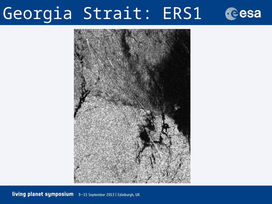
Georgia Strait: ERS1

Modelling
• Layer models– Discrete (e.g. loch, fjord)– Diffuse
• Internal wave wake model– Linearized– Far wake
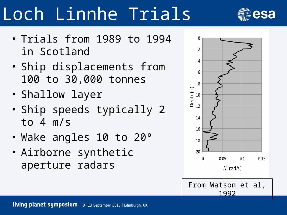
Loch Linnhe Trials• Trials from 1989 to 1994 in
Scotland• Ship displacements from 100 to
30,000 tonnes• Shallow layer• Ship speeds typically 2 to 4 m/s• Wake angles 10 to 20º• Airborne synthetic aperture radars 20
18
16
14
12
10
8
6
4
2
0
0 0.05 0.1 0.15
N (rad/s)
Dept
h (m
)From Watson et al, 1992

Wigley Hull• Canoe shaped: Parabolic in 2-D, constant draft• Useful theoretical model but block coefficient is 4/9
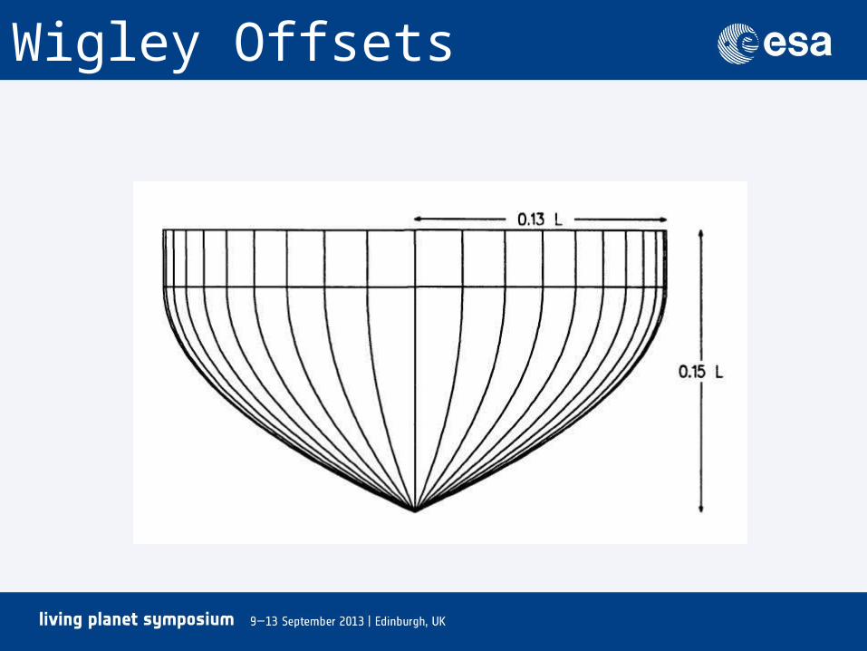
Wigley Offsets
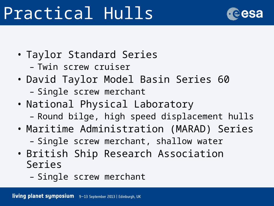
Practical Hulls
• Taylor Standard Series– Twin screw cruiser
• David Taylor Model Basin Series 60– Single screw merchant
• National Physical Laboratory– Round bilge, high speed displacement hulls
• Maritime Administration (MARAD) Series– Single screw merchant, shallow water
• British Ship Research Association Series– Single screw merchant
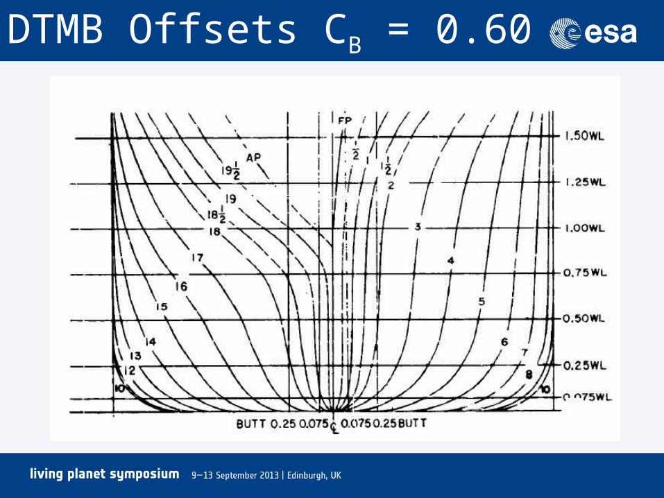
DTMB Offsets CB = 0.60
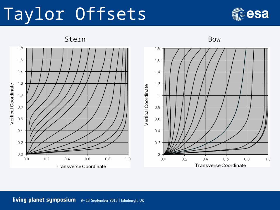
Taylor OffsetsStern Bow

Sir Tristram, 2m/s
From Watson, Chapman and Apel, 1992
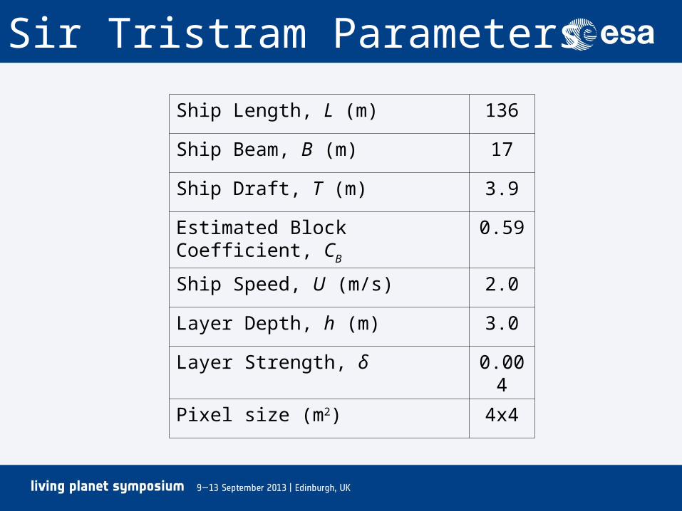
Sir Tristram Parameters
Ship Length, L (m) 136
Ship Beam, B (m) 17
Ship Draft, T (m) 3.9
Estimated Block Coefficient, CB 0.59
Ship Speed, U (m/s) 2.0
Layer Depth, h (m) 3.0
Layer Strength, δ 0.004
Pixel size (m2) 4x4
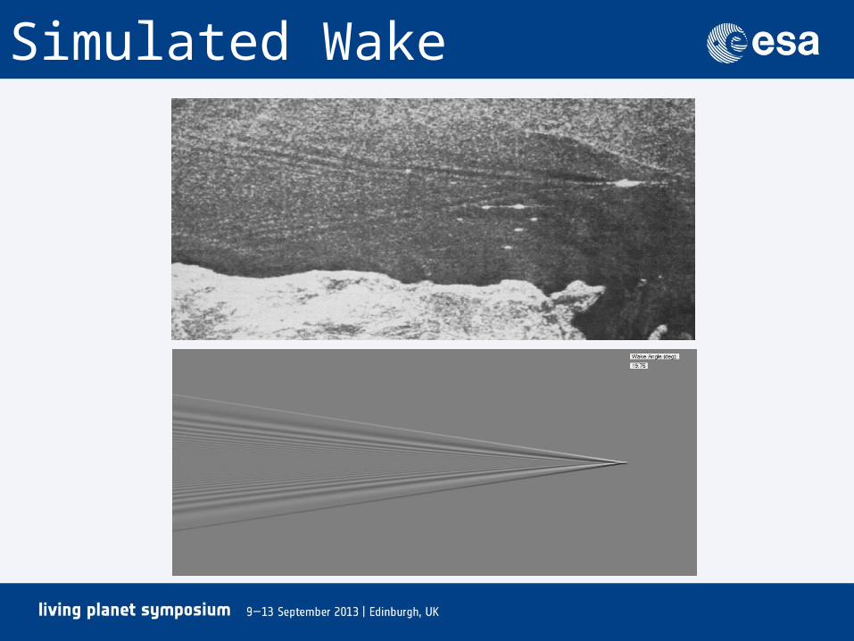
Simulated Wake

Observed Surface Velocity
From Watson et al, 1992
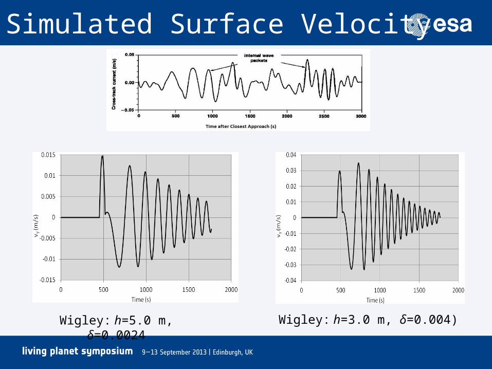
Simulated Surface Velocity
Wigley: h=5.0 m, δ=0.0024 Wigley: h=3.0 m, δ=0.004)
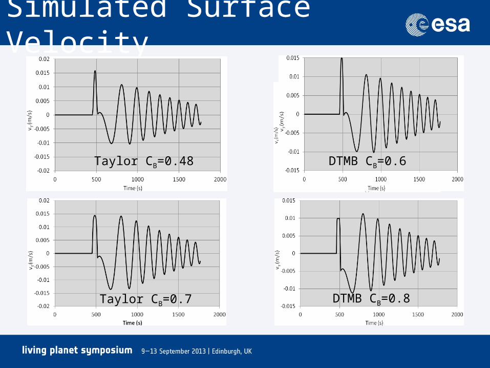
Simulated Surface Velocity
Taylor CB=0.48 DTMB CB=0.6
Taylor CB=0.7 DTMB CB=0.8
Effect of Hull Model
• In this application:– Minor changes to velocity profile as a function of
hull model– Minor changes to velocity profile as a function of
CB
– Shifts shoulder downwards in plots as CB increases
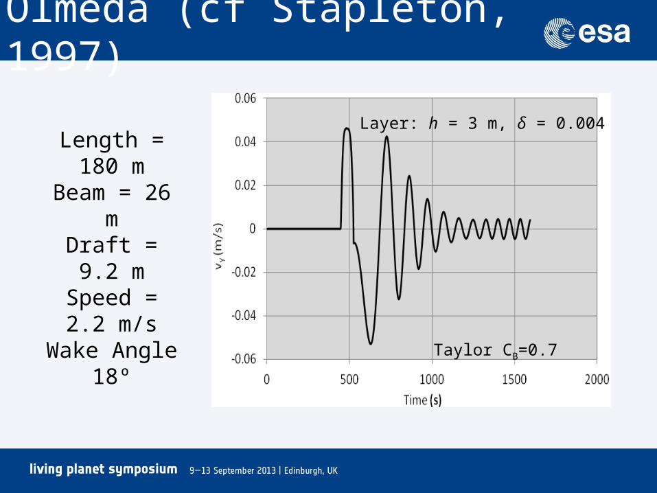
Olmeda (cf Stapleton, 1997)
Length = 180 mBeam = 26 mDraft = 9.2 m
Speed = 2.2 m/sWake Angle 18º
Layer: h = 3 m, δ = 0.004
Taylor CB=0.7

Conclusions• Simulations are reasonably consistent with
observations• Sir Tristram observed maximum water velocity
at sensor is about 3 cm/s; same as simulations• Olmeda observed maximum velocity at sensor
is about 5 cm/s; same as simulations• Wake determined mainly by block coefficient• Structure in first cycle appears to be similar in
observations and simulations