Embed Size (px)
Citation preview

Simulation of induction machine operation using a stepbystep finiteelement methodE. Vassent, G. Meunier, A. Foggia, and J. C. Sabonnadiere Citation: Journal of Applied Physics 67, 5809 (1990); doi: 10.1063/1.345971 View online: http://dx.doi.org/10.1063/1.345971 View Table of Contents: http://scitation.aip.org/content/aip/journal/jap/67/9?ver=pdfcov Published by the AIP Publishing Articles you may be interested in A step-by-step application of Danish method for generation of typical meteorological years of China J. Renewable Sustainable Energy 5, 053145 (2013); 10.1063/1.4826193 A blade-coating study using a finite-element simulation Phys. Fluids 17, 127101 (2005); 10.1063/1.2140226 FiniteElement Method in a Spreadsheet Comput. Phys. 6, 198 (1992); 10.1063/1.4823062 Stepbystep astronomy Phys. Teach. 19, 135 (1981); 10.1119/1.2340723 Simulating the behavior of the eardrum by the finiteelement method J. Acoust. Soc. Am. 56, S3 (1974); 10.1121/1.1914164
[This article is copyrighted as indicated in the article. Reuse of AIP content is subject to the terms at: http://scitation.aip.org/termsconditions. Downloaded to ] IP:
173.250.174.130 On: Sat, 06 Dec 2014 21:23:43
Simulation of induction machine operation using a step-by-step finiteaelement method
E. Vassent, G. Meunier, A. Foggia, and J. C. Sabonnadiere Laboratoire d'Electrotechnique de Grenoble (UA CNRS 355), Ensieg, BP 46, 38402 Saint Martin d'Heres, France
In order to model the operation of an induction machine when space harmonics are neglected, the magnetodynamic model with the equivalent ac magnetization plot can be used. But when we want to simulate an induction machine with an open isthmus, for instance, the space harmonics cannot be neglected and a step-by-step method is a solution to modeling its action. In this paper, we develop a means of modeling an induction machine with a nonlinear step-bystep method. The motion of the rotor is taken into account through the displacement of its mesh. The basis of the method is that after each step of the simulation we rebuild only the air gap portion of the mesh. Applied to an industrial four-pole squirrel cage induction machine with an open isthmus, this method provides accurate values of the torque on the whole range of velocity. We have compared the curves obtained by this method with those by the magnetodynamic model for many different types of induction machines. Our method shows the effects of space harmonics on torque more accurately. The curves of torque at differen t velocities give us a lot of information on effects of harmonics.
INTRODUCTION
Induction machines associated with variable frequency supplies are now more and more used in the industry as variable speed drives. The progress in semiconductors and in the reability of variable speed induction machines is competitive with respect to dc drives.
However, the design of induction machines operating the variable frequency supply requires much information, especially on the distribution of the magnetic field and the eddy currents on the rotor bars. The use of finite elements makes it possible to give this information, when no motion occurs, i.e., when the rotor is at rest.
It is then necessary to develop news algorithms to take into account (i) the motions of the rotor, and (ii) the effect of nonsinusoidal currents injected in the stator windings. The solution of these problems may easily be obtained when the supply is, or may be, sinusoidal. In that case, we developed an algorithm capable of solving the magnetodynamic Maxwell's equations. 1
This algorithm is based on the use of complex phasors associated with an equivalent B(B) curve. Although the rotor is assumed to be at rest, its motion is taken into account by the resistance of the rotor winding, as seen in the reference from of a fixed observer.
This method, which does not require a displacement technique, is efficient and accurate enough to give a good representation of the electromechanical characteristic of the machine. However, space harmonics are not adequately represented, and the influence of nonsinusoidal supplies may not be investigated.
For these reasons it has been found necessary to extend the algorithm; we developed a method, taking into account the combined effects of time and space harmonics. In that case, since complex phasors even with equivalent B(H)
curves may no longer be used, the only way to solve this problem is a time step-by-step method.
If the implementation of a step-by-step method is now quite easy, the difficulty is then to take into account the efficiency of the rotor displacement. Although some authors2
,3
have developed such techniques, we present in this paper a method in which only the air gap region is remeshed at every time step.
In the following sections we will then present the time step-by-step method, including the motion of the rotor in the modeling of a polyphase induction machine.
EQUATIONS OF THE MACHINES
The equations to be solved are the Maxwell's equation,
rotH=J,
dB rotE= -Tt'
div B= 0,
divJ= 0,
associated with the magnetic properties of the media,
B = f.1H,
( 1 )
(2)
and Ohm's law, taking into account the speed of the rotor,
J=aE+aVAB. (3)
In these equations Band H represent the magnetic induction and the magnetic field, respectively, J is the current density, f.1 is the magnetic permeability, a is the electrical conductivity, and V represents the speed of the rotor. When introducing the magnetic vector potential A, the previous equations reduce to
l( I ) aA(t) cur +a--f.1 curl A (t) at - aV(t)A curl A(t) = Jo(r), (4)
5809 J. Appl. Phys. 67 (9), 1 May 1990 0021-8979/90/095809-03$03.00 @ 1990 American Institute of Physics 5809
[This article is copyrighted as indicated in the article. Reuse of AIP content is subject to the terms at: http://scitation.aip.org/termsconditions. Downloaded to ] IP:
173.250.174.130 On: Sat, 06 Dec 2014 21:23:43
when Jo represents the current density of the source. Equation (4) has to be solved in a fixed reference frame.
In a previous paper, I a method was presented in which the vector potential A was assumed to be sinusoidal with time. The results were acceptable provided an equivalent B(H) curve be used.
Because space and time harmonics were not adequately represented, we found it necessary to go further and use a time stepping technique to solve Eq. (4) in a cross section of an induction machine. The implementation of such an algorithm requires taking into account the motion of the motor.
DEFINITION OF A DISPLACEMENT METHOD
The solution of Eq. (4) by means of a time-stepping method in a reference frame leads to a nonsymmetrical matrix because of the V term and also requires to remesh the full domain at every time step. Such a technique is time consuming and not interesting to use. To use such a difficulty, Eq. (4) is solved:
(a) in a fixed reference frame-the stator; (b) in a moving reference frame-the rotor.
The link between the two references is the motion of the rotor with respect to the stator.
The main advantage of this method is that on each reference frame the equation to be solved does not contain the V term, but at every step a new mesh has to be generated. The problem now is to have a deformable mesh that is not time consuming.
The method we found to be the most efficient is to generate one mesh for the stator and one for the rotor; these two once meshed are fixed with respect to their own reference frame. At every time step, only the airgap mesh has to be adapted.
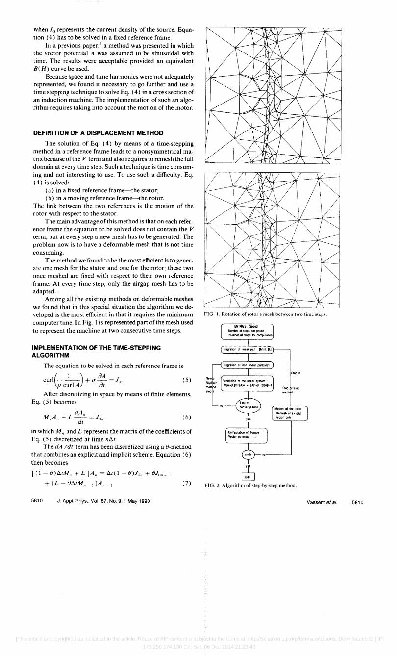
Among all the existing methods on deformable meshes we found that in this special situation the algorithm we developed is the most efficient in that it requires the minimum computer time. In Fig. I is represented part of the mesh used to represent the machine at two consecutive time steps.
IMPLEMENTATION Of THE TIME·STEPPING ALGORITHM
The equation to be solved in each reference frame is
CUrl(.. _1_) + a JA = Jo. (5) f.1. curl A at
After discretizing in space by means of finite elements, Eq. (5) becomes
dA" ill"A" + L -- = Jo,,'
dt (6)
in which M" and L represent the matrix of the coefficients of Eq. (5) discretized at time n6.t.
The dA Idt term has been discretized using a 8-method that combines an explicit and implicit scheme. Equation (6) then becomes
[( I - 8)6.tM" + L JAn = 6.t( 1 - 8)Jo" + 8JOn _ I
+ (L - 86.tMn I )A"
5810 J. Appl. Phys., Vol. 67, No.9, 1 May 1990
(7)
FIG. I. Rotation of rotor's mesh between two time steps.
step i
Stop n
Step 'I step meth d
FIG. 2. Algorithm of step-by-step method.
Vassent et al. 5810
[This article is copyrighted as indicated in the article. Reuse of AIP content is subject to the terms at: http://scitation.aip.org/termsconditions. Downloaded to ] IP:
173.250.174.130 On: Sat, 06 Dec 2014 21:23:43
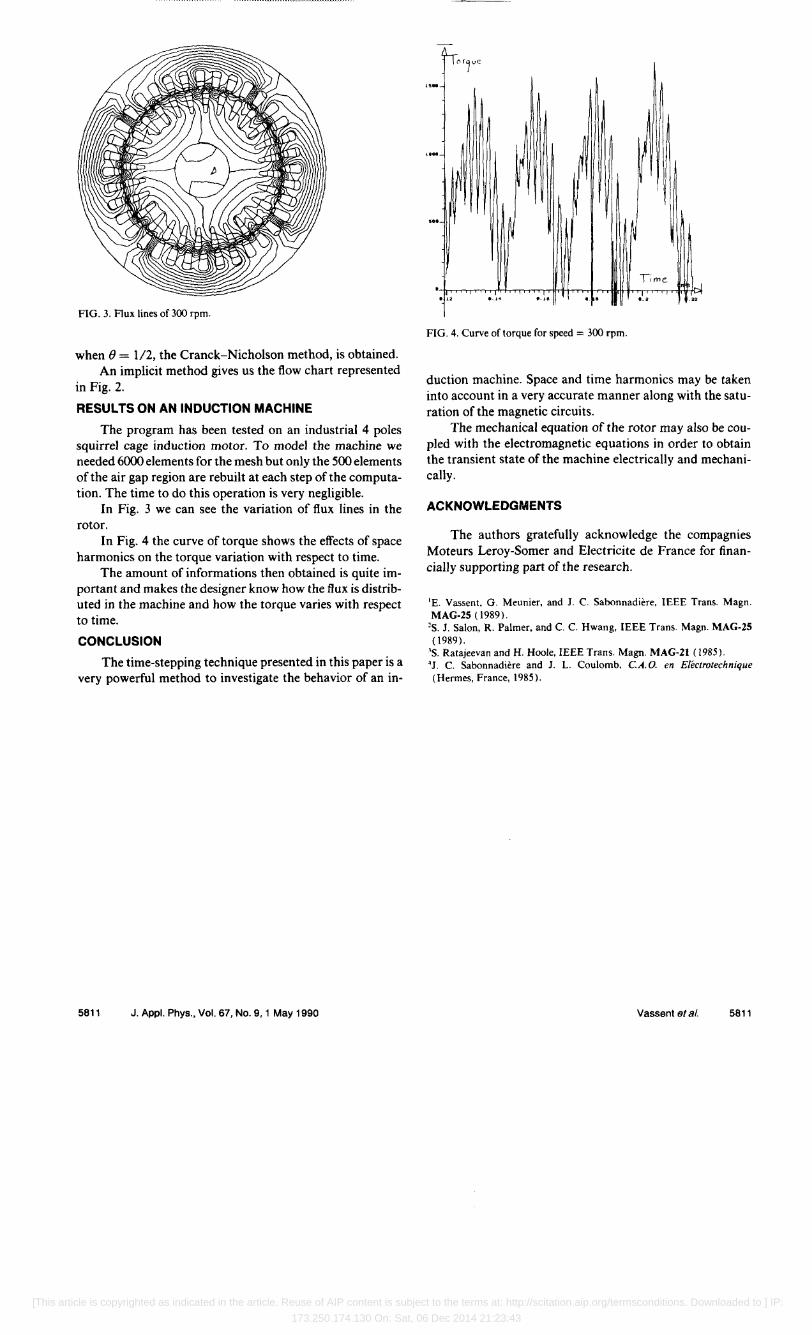
FIG. 3. Flux lines of 300 rpm.
when e = 1/2, the Cranck-Nicholson method, is obtained. An implicit method gives us the flow chart represented
in Fig. 2.
RESULTS ON AN INDUCTION MACHINE
The program has been tested on an industrial 4 poles squirrel cage induction motor. To model the machine we needed 6000 elements for the mesh but only the 500 elements of the air gap region are rebuilt at each step of the computation. The time to do this operation is very negligible.
In Fig. 3 we can see the variation of flux lines in the rotor.
In Fig. 4 the curve of torque shows the effects of space harmonics on the torque variation with respect to time.
The amount of informations then obtained is quite important and makes the designer know how the flux is distributed in the machine and how the torque varies with respect to time.
CONCLUSION
The time-stepping technique presented in this paper is a very powerful method to investigate the behavior of an in-
5811 J. Appl. Phys., Vol. 67, No.9, 1 May 1990
... N
" .1
FIG. 4. Curve of torque for speed = 300 rpm.
duction machine. Space and time harmonics may be taken into account in a very accurate manner along with the saturation of the magnetic circuits.
The mechanical equation of the rotor may also be coupled with the electromagnetic equations in order to obtain the transient state of the machine electrically and mechanically.
ACKNOWLEDGMENTS
The authors gratefully acknowledge the compagnies Moteurs Leroy-Somer and Electricite de France for financially supporting part of the research.
'E. Vassent, G. Meunier. and J. C. Sabonnadiere, IEEE Trans. Magn. MAG-25 (1989).
'So 1. Salon, R. Palmer, and C. C. Hwang, IEEE Trans. Magn. MAG·25 (1989).
'So Ratajeevan and H. Hoole, IEEE Trans. Magn. MAG·21 (1985). 4J. C. Sabonnadiere and J. 1. Coulomb. C.A.O. en Electrotechnique (Hermes, France, 1985).
Vassent et al. 5811
[This article is copyrighted as indicated in the article. Reuse of AIP content is subject to the terms at: http://scitation.aip.org/termsconditions. Downloaded to ] IP:
173.250.174.130 On: Sat, 06 Dec 2014 21:23:43


![arXiv:1210.2225v1 [math.RT] 8 Oct 2012 · 6.2. Characters of Finite Classical groups 19 7. Harish-Chandra Induction 20 7.1. Harish-Chandra Induction 20 7.2. Characters under Harish-Chandra](https://img.pdfslide.us/doc/110x75/5f70192c974bee67ac1009f7/arxiv12102225v1-mathrt-8-oct-2012-62-characters-of-finite-classical-groups.jpg)


![V'x(v,'V'xA)=j · 2020. 4. 28. · the equivalent motor circuit. Finite element analysis (FEA) in induction motors (1M) is a step towards the modern design of induction motors [15]](https://img.pdfslide.us/doc/110x75/5fc782d0c1220c0a070a382a/vxvvxaj-2020-4-28-the-equivalent-motor-circuit-finite-element-analysis.jpg)