Embed Size (px)
Citation preview
SIMULATION OF A 245 GHZ SQUARE MICROSTRlP PATCH ANIENNA USING MICROWAVE OFFICE 2000
Kua Jeak Thng
Bachelor of Engineering with Honours 1l (Electronics and Computer Engineering) 78716
2004K95 2004
Universiti IVlalaysia Sarawak
R13a BORANG PENYERAHAN TESIS
Judul SI MULA nON OF A 245 GHZ SQUARFJ1ICllOSTRIP PATC H ANTE NNA USING MICROWAVE OFFICE 2000
SESI PENGAJ1AN 20032004
Saya K UA JEAK TONG (HtT RUF BESAR)
mengaku mcmbcnarkan teslS ini dlslmpan di Pusat Khidmat Maklumat Akademlk Unlvcrsiti MalaYSia Sarawak dengan syarat-syarat kegunaan seperti berikut
Hakmtllk kertas [)fojek adalah dl bawah nama penults melainkan pcnulisan scbagal projek bersama d~m dlblayal oleh UNIMAS hakmiliknya adal ah kepunyaan UNIMAS
2 Naskhah salinan di dalam bcntuk kertas atau mikro hanya boleh dibuat dengan kebenaran bert uhs dari pada pen u li s
J Pusat Khlum a( Maklumat Akademik UN [MAS dlbenarkan membuat sallnan untuk pengajian IHcnka
4 Kertas projck hanya boleh diterbitkan dengan kebenaran penulis Bayaran royalti ad~ l aJ menglkul kadar yang dlpersetUjUI kelak
5 Saya membenarkantldak membenarkan Perpustakaan membuat sallnan kelias [)1ojek in l sebagal badan pertukaran di lt1n tara Instltusl pengaJlan tlnggi
6 bull S tla tandakan (v)
SULIT (Mengandungi maklumat yang berdarjah kes el atn ~tan uau kcpcnllngilrl Malaysia scperti yang termaktub d dalam AKTA RA HS IA RASMI 1972)
TERHAD (Mengandungl maklumat TERHAD yang telah du cnt ukan oleh organlsasil bad an di mana penyelidlkan dijalankan)
TIDAI( TERHAD
~~Ieh (TANDATANGA N PENULlS) (TANDATANGA N PENY ELl A)
Alamat Totap NO 50 PA SAR M R KIS M ET HO NG PING ENG KILlLI 98500 SRI AMAN Nama Pen vehn SARAWAK
Takh 22 March 2004
CATATAN POIOn ( yang Ii dak berk enfl n Jib krrJs Pro)d 101 SC LIT alau TERI-IAD ~ da lamp illa rl SliI J daripillda pih( b~r ~UlSjl]torltar i~i
berkenaan delgul menyerlakan sekall lemJXlh kCTt ~ s proJcl 1m Vrl il ct dc h dilfl ~d~~i~1 SUI IT al au TERHAD
Laporan Projek Tahun Akhir berikul
Tajuk Simulation of A 245GHz Square Microstrip Patch antenna using Microwave Office 2000
Nama penuli s Kua Jeak Tong
Matrik 5138
telah dibaca dan disahkan o leh
Jai~ )1 ogt MClt ~inet Hong Ping Tarikh Penyelia
I)u~at hhidmul Mllklumal Aksdemlk U IVIRStll ML WSIA SARAVoAK
943W w anlJJhan
SIMULATION OF A 245 GHZ SQUARE MICROSTRJP PATCH
ANTE NA USING MICROWAVE OFFICE 2000
PKHIOMAT MAKlUMAT AKAOEMIK UMIMAS
1111111111111111111111111 1000126532
KUA JEAK TONG
This project is submitled in partial fulfillment of the requiremen ts for the degree of Bachelor of Engineeri ng with Hono rs
(Electro nic amp Computer Engineering)
Faculty o f Engineering t rVERSlTl MALA YSIA SARAW AK
2004
ACKNOLEDGEMENTS
The author would like to express my thankfulness to hi s Project Supe rvisoL Mr
Ki smet Hong Ping for hi s giving his prec ious guidance despite his tight schedule
Beside the author would like to ex press my gratitude to his fam ily for giving me all
supports throughout the years in UN IMAS Last but not least the autho r wo uld like
to thank to hi s friends fo r the ir helps coope rati on and supports to make thi s project
complete successfull y
Dedicated to my beloved fa mily and loved ones
ABSTRAK
Kajian ini membincangkan tentang kaedah-kaedah and simulasi untuk merekabentuk
antena jenis square microstrip patch dengan menggunakan peri sian MicroWave Office
2002 Beberapa ujikaji telah dibuat untuk mendapat keputusan yang paling optimum
Kajian ini berm ula dengan pembelajaran ke atas perbagai teori tentang isyarat gelombang
mikro jeni s-jenis antena dan sifat-sifatnya Kemudian diikuti dengan pengiraan untuk
panjang and lebar (dimensi) antena serta sai z untuk sell dalam kotak simulas i peri sian
sebelum bermuJanya simulasi Beberapa parameter yang penting perlu dikcnalpasti
antaranya ialah frequency operasi pemalar dieJektrik bahan dielektrik yang digunakan dan
sebagainya perlu dikenalpasti sebelum proses simulasi dan rekaan dijalankan Akbir sekali
semua keputusan-keputusan hasil daripada peri sian daJ am bentuk carta dan graf dianalisis
Kemudian diakbiri dengan pemilihan keputusan yang paling opti mum
ABSTRACT
This research descri bes the design and simulation of the sq uare Microstrip Patch
antenna usi ng Microwave Office 2002 and addit ional enhancement experimental to
come o ut with the optimum result The research started with the theoretical stud y
about the microwave signal type of antenna and cha racteristi c of the antenna Than
following by patch dime nsion calculation and cell size calculation in the simulation
box before the research invo lves the software simulation where severa l parameter
compri sing the operation freq uency dielectric constant substrate mate rial loss
tangent and etc were preset prior to the design of the antenna Finall y analys is is
make consist of the results from the Smith Chart VSWR Chal1 Return Loss Graph
and Impedance Graph with is generate by the Microwave Office 200 1 simulation
software and come out with the optimum result
II
CHAPTERS
ONE
TWO
TABLE OF CONTENTS
NO CONTENTS
ABSTRACT
ABSTRAK
TABLE OF CONTENTS
LIST OF TABLES
LIST OF FIGURES
11
12
13
INTRODUCTION
Background
Objective
Organization of the project report
2 1
22
LITERATURE REVIEW
Introduction
Basic type of antennas
221 Wire Antennas
222 Aperture Antennas
223 Microstrip antennas
224 Reflector Antennas
225 Len Antennas
III
PAG E
11
III
XI
xii
2
J
4
5
6
6
7
8
23 Definition of important Antennas parameters 9
231 Dielectric Constant 9
232 Bandwidth 10
23J Voltage Standing Wave Ratio (VSWR) II
234 Return Loss 12
235 Efficiency 12
236 Gain3D Pattem 13
237 Polarizati on 13
238 Impedance matching 14
24 Basic Characteristic of Microstri p ante nnas 14
25 Feeding Methods 15
2 6 Methods of Analysis 18
THREE METHODOLGY 19
3 1 Introduction 19
32 Flow chart 20
32 1 Specification of antenna design 2 1
322 Calculation of the patch size 22
323 Cell size calculation 23
324 Feeding in the substrate information 25
325 Patch size drawing 27
326 Simulation and Analysis 28
33 Selection criteria for the optimum antenna design 29
V I
~ - shy---- ---
FOUR
fIVE
41
42
4J
44
45
46
5 1
52
RESULTS AND ANA LYSIS
Si mulation I
Patch size modificat ion
Port Position
Difference feeding Method
Edge modification
Double dielectric substrate
CONCLUSION AND RECOMMENDATION
Conclusion
Recorrune ndations
References
Appendix
30
30
33
36
41
44
45
49
49
50
SI
53
x
- - ---
LIST OF TABLE
Tables Pages
41 Summari es of the results 32
42 Summaries resu lts of expanding patch size horizontall y 34
43 Summaries results of expanding patch size verti call y 34
44 Summaries results of reducing patch size hori zontall y 35
45 Summari es results of reduc ing patch size verticall y 36
46 Summaries results of moving port to left 37
47 Summaries results of moving port to right 38
48 Summaries results of moving port to left down 39
49 Summari es results of movi ng port to right down 39
410 Summari es results of movi ng port to center down 40
411 Summari es results of ex pand the line size 41
412 Summari es results of reduced the line size 42
4 13 Summaries resu lts of extended of line length 43
414 Summ ari es results of reduced of line length 43
415 Summar ies results o f patch sharp mod ification 44
416 Summaries result o f the two layer substrate antenna 46
XI
----- -
LIST OF FIGIlRES
Figures Pages
2 1 Wire antenna configuration S
22 Aperture anteJUla configuration 6
23 Rectangular and circu lar Microstrip antenna 7
24 Typical Reflector configurations 8
2S Basic type of lens configuration 9
26 Microstrip Antennas 14
27 Representative shapes of Microstrip patch elements IS
28 Typical feed s for Microstrip antennas 16
29 Equiva lent ci rcuit for typical feeds 17
3 1 Fl ow chart of the design procedures 20
32 Orientation of the Patch 24
33 Substrate Info nnati on for Enclosure 2shy
34 Substrate In formation for Dielectric Layer 26
3S Substrate Infomlation fo r Boundaries 27
36 Patc h wi th the correct dimen sion 28
41 VSWR chart of simulationl 30
42 Return Loss chart J I
43 Impedance chart 31
44 Expand patch size horizontally 33
4S Expand patch size verti cally 4
xu
~---
46 Reduced patch size horizonta ll y 35
47 Red uced patch size verti cally 36
48 Move port to the left 37
49 Move pOl1 to the rig ht 37
4 10 Move port to the left down 38
4 11 Move port to the right down 39
412 Move port to the center down 40
413 Ex pand the line size 41
414 Reduced the line s ize 42
415 Extend the line length 42
416 Reduced the line length 43
417 Edge modification 44
418 Two layer substrates elect romagnet ically coupled patch 45
419 Return Loss graph (optim um results) 47
420 VSWR (o ptimum resul ts) 47
421 Impedance Graph (optimum results) 48
5 1 Patch dimension (double substrate) 49
X IIl
11
CHAPTER 1
INTRODUCTION
Background
An antennas is defined by Webstars Dictionary as a usual ly metallic device
(as a rod or wire) for radiating or receiving radio waves[2J In the simpl er words is
the region of transi ti on between a guided wave and a free space wave It is a very
impoI1ant part or component in any communicati on system to transmit or receive the
signal to or from the free space And the difference type of system requires
difference type of the antenna
The antenna is a very common device that we can easil y found in this modem
world The television antennas radio antenna hand-phone antenna and many more
electrical and electronic devices are using it Antennas a lso used in many advance
communica tion system li ke radar fo r military propose airpoM surve illance and etc
Microstrip rectangle and square patch antennas have been study and fo und
suitable as single antenna element or for array applicatio n Mierostrip antennas have
several ad vantages compared to conventiona l microwave antennas Because of th is
many ap plications in between the frequency range of IOOMHz to IOOGHz are using
thi s type of antennas
Light weight low volume and thin profile confIguration is the malO
advantages for thi s type of antennas and there are fee l more advantages in state of
the fabrication cost simpler feed ing method easily design and made with dua l
frequency and polarization and required no cavity backing In the same time the
microstrip antennas also have an easier way to integrate with microwave integrated
ci rcuir
In this document experimenta l data is compiled on a difference feeding
method the probe feed and the feed line method The experiment or simulations are
made using Microwave offi ce 2000 CAD
Positioning of the probe feed (By adjustment the probe around some
important position) size and len g1h o f the feed line and shape of the an tennas (made
the cutting on the angle of square patc h antenna) are experimented and compared
The study and experimental also included in doub le or stacked dielectric substrate
Results from all the experiments then are compared and the design with the
best result are taken as the fmal result and used in the real antenna fabrication (this
state is for the future planning)
12 Objectives
The objectives of this project are as follow
I To analyze various type of feeding methods and apply in an an tenna design
II Simulate and design the microstrip antenna or Square patch antenna using
Microwave Office 2000
11 To define the bas ic characteristic and operation of an antenna
I V Simulate and design double or stacked dielectric substrate of the square patch
antenna
2
13 Organization of the project report
This report started with the idea to design a microstrip anterma and organized
in 5 chapters Chapter I describes the basic introduction of the microstrip antermas
application and the imponant of the antenna ad vantages compared with microwave
antennas and described about the objectives of the project
Chapter 2 deal s with the literature review of the project The descriptions
include the bas ic type of an termas some impOJ1ant definition for antennas parameters
like dielectric e lectric constant band width VSWR loss tangent and so for There
also described basic characteristic of the microstrip patch antennas and type of the
feeding methods for the antermas
The procedures to design started from the begirming of the patch dimension
calculation all the parameters apply in the simulation software (Microwave office
2000) and reach the final results which are di scussed in Chapter 3
The analysis is make consist of the results from the experiments the
compan son between various type of experiments and the se lection criteria for the
optimum antermas design are described in Chapter 4
Chapter 5 di scusses the conclusion of the project the fin~i result with is the
best from all the designs and recommendation is made to the project and the further
plarming to improved the project
3
CHAPTER 2
LITERATURE REVIEW
21 Introduction
As we know antennas are fundamental components of all radio systems and
use free space as the carrying medium They are used to interface the transmitter of
receiver to free space
The operation of a simple transmitting antenna can be illustrated by thinking
of an o pen-circuit cable with two conductors At the ope n e nd a phase reversa l
results causing some of the incident voltage to be rad iated away from the
transmission line instead of reflected as is normally the case The radiated energy is
in the form of transverse elect(Omagnetic waves a nd the inc reas ing o r decreasing of
the di stance between the conductors can vary the amount of radiatio n emitted [3]
Bas ically a trans mitting antenna trans mits by exciting it a t the base (or at a
pair of anti nodes) while in a receiving antennas the applied electromagneti c fi eld is
di stributed throughout the entire length of the antenna to receive the s igna l
The magnetic field that the transmitting antenna radiates will produce an
electric current on any metal surface that it strikes Howeve r if the metal that the
signal strikes has a certain length re la ti on to the wavelength the induced CUITent will
be much stronger on the object
4
22 Basic type of antennas
As we know difference type of application is the key of c hoos ing the
difference an tennas The consideration is making base on the quality of the incoming
and outgo ing signal So in thi s section we will di scuss briefly some various types of
antennas
221 Wire Antennas
Wire antennas have several of shape such as a stra ight wire (dipole) loop and
he li x as shown in Figure 2 1
Wire antennas are the simplest type of antennas and the advantages of this
type of an tennas are more relate to the shape with are li ghtweight fabricate and easy
to feed
J - 0 1
(a) Dipole (b) Circular (square) loop
(c) Heli x
Figure 2 1 Wire antenna configurations
5
222 Aperture Antennas
Aperture antennas are most common type of antennas in microwave
antennas There are many different geometrica l configurations and figure 22 shows
the most popular shape that usury been used The advantages of this type of antennas
are it easy to mount on any surface and their opening can be covered with a dielectri c
material to protect them from envirorunental conditions Usually aperture antennas
are used for space application because of the high-speed applications is c riti ca l [3]
(a) Pyramidal horn
4t~~_ _IJft
L (b) Conical horn
(e) Rectangular waveguide
figure 22 Aperture antenna configurations
223 Microstrip Antennas
Microstrip antennas is another type of antennas with also very popular in
modem communication wo rld This is because of the characteristic of the antennas
with is low profile conformable to any surfaces simple and inexpensive to fabricate
usi ng modem printed circuit technology mechanically robust when mounted on rigid
6
surfaces compatible with MMIC designs and very ve rsat ile in tenn s of resonant
frequency Figure 23 shows the rectangular and circuit micros trip (patch) antennas
[2]
PaLch
I lt r
Ground plane
(a) Rectangular Patch antenna
Ground plane
(b) Circular Patch antenna
Figure 23 Rectangular and Circular Microstrip (patch) antenna
224 Reflec tor Antennas
A refl ector antenna is a most powerful in much type o f anlerulas in the
transmitting and receiving signal over the great di stance Thi s type of antenna has
been built with the large diameter up to 306m because it needed to achi eve the high
gain and to transmit and receive signal after millions of miles of travel Figure 24
(a) (b) (c) shown three common configuration of parabolic and comer refl ector
antenna [3]
7
Refl ec tor
(a) Parabolic refl ecto r wi th front feed
euro~33 Sub -refl ector
(a) Parabolic reflector with sub-feed
(a) Corner reflector
Figure 24 Typical Reflector configurations
The lens antenna is one type of the antennas with is the ideal of radiate power
delivered to it and form s the transmitter in des ired directions Difference shape of
geometrical configuration and material of the lenses can transform various forms of
divergent energy into plane waves Figure 25 shows some f01111s of the lens antennas
[3]
8
Rotational Lens n gt I
=lt~+-----) Rotational Lens n lt 1
Figure 25 Basic type of lens configuration
23 Definition of important Antennas Parameters
In any antennas design some of the important parameters are need to be
cons idered such as die lectric constant bandwidth VSWR return loss efficiency
antennas gain direct ivity polarization and impedance matching
23 1 Dielectric Constant
The dielectric constant is the rel ative permittivity of a material It is
dimensionless and always greater than 1 A dielectric constant nf I is equivalent to
the permittivity of a vacuum which is a fundamental constant (associated with the
speed of light) In other words vacu um has the lowest possible permittiv ity
9
The higher figures a material show for it permittivity the slower the radio
waves will pass and thus making a radio of signal For example a 24 GHz frequency
presents a wavelength shorter than 12cm This means that if a n ante nna is covered
wi th a material with high pennitti vity it will for the same freque ncy find its resonant
point with a shorter (smaller) antenna than would have been the case if it were an
ope n wire This sounds good when you want to build antennas fo r small devices T he
higher the penninivity more the inferior and nalTow-banded the antenna will get
Also a very small antenna has fewer surfaces to absorb the incoming wave
232 Bandwidth
Bandwidth is differing of the higher frequency and the lower freq uency
Nonnally a radio musL need La work on mUltiple frequencies For example the
24GHz ISM band used by Blue-tooth devices has a range from 2400-248J MHz in
this band Blue-Looth communication uses 78 channels for its frequency hopping
technique I MHz between each charmel
This means thaLLhe antenna must perfonn well over a range of frequency So
the goal must be to make it resonant in the middle of that band The term that is
important here is bandwidth or how much band your anLenna works well ove r A
method to judge the efficiently of antenna is using the VSWR measurement
10

ABSTRAK
Kajian ini membincangkan tentang kaedah-kaedah and simulasi untuk merekabentuk
antena jenis square microstrip patch dengan menggunakan peri sian MicroWave Office
2002 Beberapa ujikaji telah dibuat untuk mendapat keputusan yang paling optimum
Kajian ini berm ula dengan pembelajaran ke atas perbagai teori tentang isyarat gelombang
mikro jeni s-jenis antena dan sifat-sifatnya Kemudian diikuti dengan pengiraan untuk
panjang and lebar (dimensi) antena serta sai z untuk sell dalam kotak simulas i peri sian
sebelum bermuJanya simulasi Beberapa parameter yang penting perlu dikcnalpasti
antaranya ialah frequency operasi pemalar dieJektrik bahan dielektrik yang digunakan dan
sebagainya perlu dikenalpasti sebelum proses simulasi dan rekaan dijalankan Akbir sekali
semua keputusan-keputusan hasil daripada peri sian daJ am bentuk carta dan graf dianalisis
Kemudian diakbiri dengan pemilihan keputusan yang paling opti mum
ABSTRACT
This research descri bes the design and simulation of the sq uare Microstrip Patch
antenna usi ng Microwave Office 2002 and addit ional enhancement experimental to
come o ut with the optimum result The research started with the theoretical stud y
about the microwave signal type of antenna and cha racteristi c of the antenna Than
following by patch dime nsion calculation and cell size calculation in the simulation
box before the research invo lves the software simulation where severa l parameter
compri sing the operation freq uency dielectric constant substrate mate rial loss
tangent and etc were preset prior to the design of the antenna Finall y analys is is
make consist of the results from the Smith Chart VSWR Chal1 Return Loss Graph
and Impedance Graph with is generate by the Microwave Office 200 1 simulation
software and come out with the optimum result
II
CHAPTERS
ONE
TWO
TABLE OF CONTENTS
NO CONTENTS
ABSTRACT
ABSTRAK
TABLE OF CONTENTS
LIST OF TABLES
LIST OF FIGURES
11
12
13
INTRODUCTION
Background
Objective
Organization of the project report
2 1
22
LITERATURE REVIEW
Introduction
Basic type of antennas
221 Wire Antennas
222 Aperture Antennas
223 Microstrip antennas
224 Reflector Antennas
225 Len Antennas
III
PAG E
11
III
XI
xii
2
J
4
5
6
6
7
8
23 Definition of important Antennas parameters 9
231 Dielectric Constant 9
232 Bandwidth 10
23J Voltage Standing Wave Ratio (VSWR) II
234 Return Loss 12
235 Efficiency 12
236 Gain3D Pattem 13
237 Polarizati on 13
238 Impedance matching 14
24 Basic Characteristic of Microstri p ante nnas 14
25 Feeding Methods 15
2 6 Methods of Analysis 18
THREE METHODOLGY 19
3 1 Introduction 19
32 Flow chart 20
32 1 Specification of antenna design 2 1
322 Calculation of the patch size 22
323 Cell size calculation 23
324 Feeding in the substrate information 25
325 Patch size drawing 27
326 Simulation and Analysis 28
33 Selection criteria for the optimum antenna design 29
V I
~ - shy---- ---
FOUR
fIVE
41
42
4J
44
45
46
5 1
52
RESULTS AND ANA LYSIS
Si mulation I
Patch size modificat ion
Port Position
Difference feeding Method
Edge modification
Double dielectric substrate
CONCLUSION AND RECOMMENDATION
Conclusion
Recorrune ndations
References
Appendix
30
30
33
36
41
44
45
49
49
50
SI
53
x
- - ---
LIST OF TABLE
Tables Pages
41 Summari es of the results 32
42 Summaries resu lts of expanding patch size horizontall y 34
43 Summaries results of expanding patch size verti call y 34
44 Summaries results of reducing patch size hori zontall y 35
45 Summari es results of reduc ing patch size verticall y 36
46 Summaries results of moving port to left 37
47 Summaries results of moving port to right 38
48 Summaries results of moving port to left down 39
49 Summari es results of movi ng port to right down 39
410 Summari es results of movi ng port to center down 40
411 Summari es results of ex pand the line size 41
412 Summari es results of reduced the line size 42
4 13 Summaries resu lts of extended of line length 43
414 Summ ari es results of reduced of line length 43
415 Summar ies results o f patch sharp mod ification 44
416 Summaries result o f the two layer substrate antenna 46
XI
----- -
LIST OF FIGIlRES
Figures Pages
2 1 Wire antenna configuration S
22 Aperture anteJUla configuration 6
23 Rectangular and circu lar Microstrip antenna 7
24 Typical Reflector configurations 8
2S Basic type of lens configuration 9
26 Microstrip Antennas 14
27 Representative shapes of Microstrip patch elements IS
28 Typical feed s for Microstrip antennas 16
29 Equiva lent ci rcuit for typical feeds 17
3 1 Fl ow chart of the design procedures 20
32 Orientation of the Patch 24
33 Substrate Info nnati on for Enclosure 2shy
34 Substrate In formation for Dielectric Layer 26
3S Substrate Infomlation fo r Boundaries 27
36 Patc h wi th the correct dimen sion 28
41 VSWR chart of simulationl 30
42 Return Loss chart J I
43 Impedance chart 31
44 Expand patch size horizontally 33
4S Expand patch size verti cally 4
xu
~---
46 Reduced patch size horizonta ll y 35
47 Red uced patch size verti cally 36
48 Move port to the left 37
49 Move pOl1 to the rig ht 37
4 10 Move port to the left down 38
4 11 Move port to the right down 39
412 Move port to the center down 40
413 Ex pand the line size 41
414 Reduced the line s ize 42
415 Extend the line length 42
416 Reduced the line length 43
417 Edge modification 44
418 Two layer substrates elect romagnet ically coupled patch 45
419 Return Loss graph (optim um results) 47
420 VSWR (o ptimum resul ts) 47
421 Impedance Graph (optimum results) 48
5 1 Patch dimension (double substrate) 49
X IIl
11
CHAPTER 1
INTRODUCTION
Background
An antennas is defined by Webstars Dictionary as a usual ly metallic device
(as a rod or wire) for radiating or receiving radio waves[2J In the simpl er words is
the region of transi ti on between a guided wave and a free space wave It is a very
impoI1ant part or component in any communicati on system to transmit or receive the
signal to or from the free space And the difference type of system requires
difference type of the antenna
The antenna is a very common device that we can easil y found in this modem
world The television antennas radio antenna hand-phone antenna and many more
electrical and electronic devices are using it Antennas a lso used in many advance
communica tion system li ke radar fo r military propose airpoM surve illance and etc
Microstrip rectangle and square patch antennas have been study and fo und
suitable as single antenna element or for array applicatio n Mierostrip antennas have
several ad vantages compared to conventiona l microwave antennas Because of th is
many ap plications in between the frequency range of IOOMHz to IOOGHz are using
thi s type of antennas
Light weight low volume and thin profile confIguration is the malO
advantages for thi s type of antennas and there are fee l more advantages in state of
the fabrication cost simpler feed ing method easily design and made with dua l
frequency and polarization and required no cavity backing In the same time the
microstrip antennas also have an easier way to integrate with microwave integrated
ci rcuir
In this document experimenta l data is compiled on a difference feeding
method the probe feed and the feed line method The experiment or simulations are
made using Microwave offi ce 2000 CAD
Positioning of the probe feed (By adjustment the probe around some
important position) size and len g1h o f the feed line and shape of the an tennas (made
the cutting on the angle of square patc h antenna) are experimented and compared
The study and experimental also included in doub le or stacked dielectric substrate
Results from all the experiments then are compared and the design with the
best result are taken as the fmal result and used in the real antenna fabrication (this
state is for the future planning)
12 Objectives
The objectives of this project are as follow
I To analyze various type of feeding methods and apply in an an tenna design
II Simulate and design the microstrip antenna or Square patch antenna using
Microwave Office 2000
11 To define the bas ic characteristic and operation of an antenna
I V Simulate and design double or stacked dielectric substrate of the square patch
antenna
2
13 Organization of the project report
This report started with the idea to design a microstrip anterma and organized
in 5 chapters Chapter I describes the basic introduction of the microstrip antermas
application and the imponant of the antenna ad vantages compared with microwave
antennas and described about the objectives of the project
Chapter 2 deal s with the literature review of the project The descriptions
include the bas ic type of an termas some impOJ1ant definition for antennas parameters
like dielectric e lectric constant band width VSWR loss tangent and so for There
also described basic characteristic of the microstrip patch antennas and type of the
feeding methods for the antermas
The procedures to design started from the begirming of the patch dimension
calculation all the parameters apply in the simulation software (Microwave office
2000) and reach the final results which are di scussed in Chapter 3
The analysis is make consist of the results from the experiments the
compan son between various type of experiments and the se lection criteria for the
optimum antermas design are described in Chapter 4
Chapter 5 di scusses the conclusion of the project the fin~i result with is the
best from all the designs and recommendation is made to the project and the further
plarming to improved the project
3
CHAPTER 2
LITERATURE REVIEW
21 Introduction
As we know antennas are fundamental components of all radio systems and
use free space as the carrying medium They are used to interface the transmitter of
receiver to free space
The operation of a simple transmitting antenna can be illustrated by thinking
of an o pen-circuit cable with two conductors At the ope n e nd a phase reversa l
results causing some of the incident voltage to be rad iated away from the
transmission line instead of reflected as is normally the case The radiated energy is
in the form of transverse elect(Omagnetic waves a nd the inc reas ing o r decreasing of
the di stance between the conductors can vary the amount of radiatio n emitted [3]
Bas ically a trans mitting antenna trans mits by exciting it a t the base (or at a
pair of anti nodes) while in a receiving antennas the applied electromagneti c fi eld is
di stributed throughout the entire length of the antenna to receive the s igna l
The magnetic field that the transmitting antenna radiates will produce an
electric current on any metal surface that it strikes Howeve r if the metal that the
signal strikes has a certain length re la ti on to the wavelength the induced CUITent will
be much stronger on the object
4
22 Basic type of antennas
As we know difference type of application is the key of c hoos ing the
difference an tennas The consideration is making base on the quality of the incoming
and outgo ing signal So in thi s section we will di scuss briefly some various types of
antennas
221 Wire Antennas
Wire antennas have several of shape such as a stra ight wire (dipole) loop and
he li x as shown in Figure 2 1
Wire antennas are the simplest type of antennas and the advantages of this
type of an tennas are more relate to the shape with are li ghtweight fabricate and easy
to feed
J - 0 1
(a) Dipole (b) Circular (square) loop
(c) Heli x
Figure 2 1 Wire antenna configurations
5
222 Aperture Antennas
Aperture antennas are most common type of antennas in microwave
antennas There are many different geometrica l configurations and figure 22 shows
the most popular shape that usury been used The advantages of this type of antennas
are it easy to mount on any surface and their opening can be covered with a dielectri c
material to protect them from envirorunental conditions Usually aperture antennas
are used for space application because of the high-speed applications is c riti ca l [3]
(a) Pyramidal horn
4t~~_ _IJft
L (b) Conical horn
(e) Rectangular waveguide
figure 22 Aperture antenna configurations
223 Microstrip Antennas
Microstrip antennas is another type of antennas with also very popular in
modem communication wo rld This is because of the characteristic of the antennas
with is low profile conformable to any surfaces simple and inexpensive to fabricate
usi ng modem printed circuit technology mechanically robust when mounted on rigid
6
surfaces compatible with MMIC designs and very ve rsat ile in tenn s of resonant
frequency Figure 23 shows the rectangular and circuit micros trip (patch) antennas
[2]
PaLch
I lt r
Ground plane
(a) Rectangular Patch antenna
Ground plane
(b) Circular Patch antenna
Figure 23 Rectangular and Circular Microstrip (patch) antenna
224 Reflec tor Antennas
A refl ector antenna is a most powerful in much type o f anlerulas in the
transmitting and receiving signal over the great di stance Thi s type of antenna has
been built with the large diameter up to 306m because it needed to achi eve the high
gain and to transmit and receive signal after millions of miles of travel Figure 24
(a) (b) (c) shown three common configuration of parabolic and comer refl ector
antenna [3]
7
Refl ec tor
(a) Parabolic refl ecto r wi th front feed
euro~33 Sub -refl ector
(a) Parabolic reflector with sub-feed
(a) Corner reflector
Figure 24 Typical Reflector configurations
The lens antenna is one type of the antennas with is the ideal of radiate power
delivered to it and form s the transmitter in des ired directions Difference shape of
geometrical configuration and material of the lenses can transform various forms of
divergent energy into plane waves Figure 25 shows some f01111s of the lens antennas
[3]
8
Rotational Lens n gt I
=lt~+-----) Rotational Lens n lt 1
Figure 25 Basic type of lens configuration
23 Definition of important Antennas Parameters
In any antennas design some of the important parameters are need to be
cons idered such as die lectric constant bandwidth VSWR return loss efficiency
antennas gain direct ivity polarization and impedance matching
23 1 Dielectric Constant
The dielectric constant is the rel ative permittivity of a material It is
dimensionless and always greater than 1 A dielectric constant nf I is equivalent to
the permittivity of a vacuum which is a fundamental constant (associated with the
speed of light) In other words vacu um has the lowest possible permittiv ity
9
The higher figures a material show for it permittivity the slower the radio
waves will pass and thus making a radio of signal For example a 24 GHz frequency
presents a wavelength shorter than 12cm This means that if a n ante nna is covered
wi th a material with high pennitti vity it will for the same freque ncy find its resonant
point with a shorter (smaller) antenna than would have been the case if it were an
ope n wire This sounds good when you want to build antennas fo r small devices T he
higher the penninivity more the inferior and nalTow-banded the antenna will get
Also a very small antenna has fewer surfaces to absorb the incoming wave
232 Bandwidth
Bandwidth is differing of the higher frequency and the lower freq uency
Nonnally a radio musL need La work on mUltiple frequencies For example the
24GHz ISM band used by Blue-tooth devices has a range from 2400-248J MHz in
this band Blue-Looth communication uses 78 channels for its frequency hopping
technique I MHz between each charmel
This means thaLLhe antenna must perfonn well over a range of frequency So
the goal must be to make it resonant in the middle of that band The term that is
important here is bandwidth or how much band your anLenna works well ove r A
method to judge the efficiently of antenna is using the VSWR measurement
10

ABSTRACT
This research descri bes the design and simulation of the sq uare Microstrip Patch
antenna usi ng Microwave Office 2002 and addit ional enhancement experimental to
come o ut with the optimum result The research started with the theoretical stud y
about the microwave signal type of antenna and cha racteristi c of the antenna Than
following by patch dime nsion calculation and cell size calculation in the simulation
box before the research invo lves the software simulation where severa l parameter
compri sing the operation freq uency dielectric constant substrate mate rial loss
tangent and etc were preset prior to the design of the antenna Finall y analys is is
make consist of the results from the Smith Chart VSWR Chal1 Return Loss Graph
and Impedance Graph with is generate by the Microwave Office 200 1 simulation
software and come out with the optimum result
II
CHAPTERS
ONE
TWO
TABLE OF CONTENTS
NO CONTENTS
ABSTRACT
ABSTRAK
TABLE OF CONTENTS
LIST OF TABLES
LIST OF FIGURES
11
12
13
INTRODUCTION
Background
Objective
Organization of the project report
2 1
22
LITERATURE REVIEW
Introduction
Basic type of antennas
221 Wire Antennas
222 Aperture Antennas
223 Microstrip antennas
224 Reflector Antennas
225 Len Antennas
III
PAG E
11
III
XI
xii
2
J
4
5
6
6
7
8
23 Definition of important Antennas parameters 9
231 Dielectric Constant 9
232 Bandwidth 10
23J Voltage Standing Wave Ratio (VSWR) II
234 Return Loss 12
235 Efficiency 12
236 Gain3D Pattem 13
237 Polarizati on 13
238 Impedance matching 14
24 Basic Characteristic of Microstri p ante nnas 14
25 Feeding Methods 15
2 6 Methods of Analysis 18
THREE METHODOLGY 19
3 1 Introduction 19
32 Flow chart 20
32 1 Specification of antenna design 2 1
322 Calculation of the patch size 22
323 Cell size calculation 23
324 Feeding in the substrate information 25
325 Patch size drawing 27
326 Simulation and Analysis 28
33 Selection criteria for the optimum antenna design 29
V I
~ - shy---- ---
FOUR
fIVE
41
42
4J
44
45
46
5 1
52
RESULTS AND ANA LYSIS
Si mulation I
Patch size modificat ion
Port Position
Difference feeding Method
Edge modification
Double dielectric substrate
CONCLUSION AND RECOMMENDATION
Conclusion
Recorrune ndations
References
Appendix
30
30
33
36
41
44
45
49
49
50
SI
53
x
- - ---
LIST OF TABLE
Tables Pages
41 Summari es of the results 32
42 Summaries resu lts of expanding patch size horizontall y 34
43 Summaries results of expanding patch size verti call y 34
44 Summaries results of reducing patch size hori zontall y 35
45 Summari es results of reduc ing patch size verticall y 36
46 Summaries results of moving port to left 37
47 Summaries results of moving port to right 38
48 Summaries results of moving port to left down 39
49 Summari es results of movi ng port to right down 39
410 Summari es results of movi ng port to center down 40
411 Summari es results of ex pand the line size 41
412 Summari es results of reduced the line size 42
4 13 Summaries resu lts of extended of line length 43
414 Summ ari es results of reduced of line length 43
415 Summar ies results o f patch sharp mod ification 44
416 Summaries result o f the two layer substrate antenna 46
XI
----- -
LIST OF FIGIlRES
Figures Pages
2 1 Wire antenna configuration S
22 Aperture anteJUla configuration 6
23 Rectangular and circu lar Microstrip antenna 7
24 Typical Reflector configurations 8
2S Basic type of lens configuration 9
26 Microstrip Antennas 14
27 Representative shapes of Microstrip patch elements IS
28 Typical feed s for Microstrip antennas 16
29 Equiva lent ci rcuit for typical feeds 17
3 1 Fl ow chart of the design procedures 20
32 Orientation of the Patch 24
33 Substrate Info nnati on for Enclosure 2shy
34 Substrate In formation for Dielectric Layer 26
3S Substrate Infomlation fo r Boundaries 27
36 Patc h wi th the correct dimen sion 28
41 VSWR chart of simulationl 30
42 Return Loss chart J I
43 Impedance chart 31
44 Expand patch size horizontally 33
4S Expand patch size verti cally 4
xu
~---
46 Reduced patch size horizonta ll y 35
47 Red uced patch size verti cally 36
48 Move port to the left 37
49 Move pOl1 to the rig ht 37
4 10 Move port to the left down 38
4 11 Move port to the right down 39
412 Move port to the center down 40
413 Ex pand the line size 41
414 Reduced the line s ize 42
415 Extend the line length 42
416 Reduced the line length 43
417 Edge modification 44
418 Two layer substrates elect romagnet ically coupled patch 45
419 Return Loss graph (optim um results) 47
420 VSWR (o ptimum resul ts) 47
421 Impedance Graph (optimum results) 48
5 1 Patch dimension (double substrate) 49
X IIl
11
CHAPTER 1
INTRODUCTION
Background
An antennas is defined by Webstars Dictionary as a usual ly metallic device
(as a rod or wire) for radiating or receiving radio waves[2J In the simpl er words is
the region of transi ti on between a guided wave and a free space wave It is a very
impoI1ant part or component in any communicati on system to transmit or receive the
signal to or from the free space And the difference type of system requires
difference type of the antenna
The antenna is a very common device that we can easil y found in this modem
world The television antennas radio antenna hand-phone antenna and many more
electrical and electronic devices are using it Antennas a lso used in many advance
communica tion system li ke radar fo r military propose airpoM surve illance and etc
Microstrip rectangle and square patch antennas have been study and fo und
suitable as single antenna element or for array applicatio n Mierostrip antennas have
several ad vantages compared to conventiona l microwave antennas Because of th is
many ap plications in between the frequency range of IOOMHz to IOOGHz are using
thi s type of antennas
Light weight low volume and thin profile confIguration is the malO
advantages for thi s type of antennas and there are fee l more advantages in state of
the fabrication cost simpler feed ing method easily design and made with dua l
frequency and polarization and required no cavity backing In the same time the
microstrip antennas also have an easier way to integrate with microwave integrated
ci rcuir
In this document experimenta l data is compiled on a difference feeding
method the probe feed and the feed line method The experiment or simulations are
made using Microwave offi ce 2000 CAD
Positioning of the probe feed (By adjustment the probe around some
important position) size and len g1h o f the feed line and shape of the an tennas (made
the cutting on the angle of square patc h antenna) are experimented and compared
The study and experimental also included in doub le or stacked dielectric substrate
Results from all the experiments then are compared and the design with the
best result are taken as the fmal result and used in the real antenna fabrication (this
state is for the future planning)
12 Objectives
The objectives of this project are as follow
I To analyze various type of feeding methods and apply in an an tenna design
II Simulate and design the microstrip antenna or Square patch antenna using
Microwave Office 2000
11 To define the bas ic characteristic and operation of an antenna
I V Simulate and design double or stacked dielectric substrate of the square patch
antenna
2
13 Organization of the project report
This report started with the idea to design a microstrip anterma and organized
in 5 chapters Chapter I describes the basic introduction of the microstrip antermas
application and the imponant of the antenna ad vantages compared with microwave
antennas and described about the objectives of the project
Chapter 2 deal s with the literature review of the project The descriptions
include the bas ic type of an termas some impOJ1ant definition for antennas parameters
like dielectric e lectric constant band width VSWR loss tangent and so for There
also described basic characteristic of the microstrip patch antennas and type of the
feeding methods for the antermas
The procedures to design started from the begirming of the patch dimension
calculation all the parameters apply in the simulation software (Microwave office
2000) and reach the final results which are di scussed in Chapter 3
The analysis is make consist of the results from the experiments the
compan son between various type of experiments and the se lection criteria for the
optimum antermas design are described in Chapter 4
Chapter 5 di scusses the conclusion of the project the fin~i result with is the
best from all the designs and recommendation is made to the project and the further
plarming to improved the project
3
CHAPTER 2
LITERATURE REVIEW
21 Introduction
As we know antennas are fundamental components of all radio systems and
use free space as the carrying medium They are used to interface the transmitter of
receiver to free space
The operation of a simple transmitting antenna can be illustrated by thinking
of an o pen-circuit cable with two conductors At the ope n e nd a phase reversa l
results causing some of the incident voltage to be rad iated away from the
transmission line instead of reflected as is normally the case The radiated energy is
in the form of transverse elect(Omagnetic waves a nd the inc reas ing o r decreasing of
the di stance between the conductors can vary the amount of radiatio n emitted [3]
Bas ically a trans mitting antenna trans mits by exciting it a t the base (or at a
pair of anti nodes) while in a receiving antennas the applied electromagneti c fi eld is
di stributed throughout the entire length of the antenna to receive the s igna l
The magnetic field that the transmitting antenna radiates will produce an
electric current on any metal surface that it strikes Howeve r if the metal that the
signal strikes has a certain length re la ti on to the wavelength the induced CUITent will
be much stronger on the object
4
22 Basic type of antennas
As we know difference type of application is the key of c hoos ing the
difference an tennas The consideration is making base on the quality of the incoming
and outgo ing signal So in thi s section we will di scuss briefly some various types of
antennas
221 Wire Antennas
Wire antennas have several of shape such as a stra ight wire (dipole) loop and
he li x as shown in Figure 2 1
Wire antennas are the simplest type of antennas and the advantages of this
type of an tennas are more relate to the shape with are li ghtweight fabricate and easy
to feed
J - 0 1
(a) Dipole (b) Circular (square) loop
(c) Heli x
Figure 2 1 Wire antenna configurations
5
222 Aperture Antennas
Aperture antennas are most common type of antennas in microwave
antennas There are many different geometrica l configurations and figure 22 shows
the most popular shape that usury been used The advantages of this type of antennas
are it easy to mount on any surface and their opening can be covered with a dielectri c
material to protect them from envirorunental conditions Usually aperture antennas
are used for space application because of the high-speed applications is c riti ca l [3]
(a) Pyramidal horn
4t~~_ _IJft
L (b) Conical horn
(e) Rectangular waveguide
figure 22 Aperture antenna configurations
223 Microstrip Antennas
Microstrip antennas is another type of antennas with also very popular in
modem communication wo rld This is because of the characteristic of the antennas
with is low profile conformable to any surfaces simple and inexpensive to fabricate
usi ng modem printed circuit technology mechanically robust when mounted on rigid
6
surfaces compatible with MMIC designs and very ve rsat ile in tenn s of resonant
frequency Figure 23 shows the rectangular and circuit micros trip (patch) antennas
[2]
PaLch
I lt r
Ground plane
(a) Rectangular Patch antenna
Ground plane
(b) Circular Patch antenna
Figure 23 Rectangular and Circular Microstrip (patch) antenna
224 Reflec tor Antennas
A refl ector antenna is a most powerful in much type o f anlerulas in the
transmitting and receiving signal over the great di stance Thi s type of antenna has
been built with the large diameter up to 306m because it needed to achi eve the high
gain and to transmit and receive signal after millions of miles of travel Figure 24
(a) (b) (c) shown three common configuration of parabolic and comer refl ector
antenna [3]
7
Refl ec tor
(a) Parabolic refl ecto r wi th front feed
euro~33 Sub -refl ector
(a) Parabolic reflector with sub-feed
(a) Corner reflector
Figure 24 Typical Reflector configurations
The lens antenna is one type of the antennas with is the ideal of radiate power
delivered to it and form s the transmitter in des ired directions Difference shape of
geometrical configuration and material of the lenses can transform various forms of
divergent energy into plane waves Figure 25 shows some f01111s of the lens antennas
[3]
8
Rotational Lens n gt I
=lt~+-----) Rotational Lens n lt 1
Figure 25 Basic type of lens configuration
23 Definition of important Antennas Parameters
In any antennas design some of the important parameters are need to be
cons idered such as die lectric constant bandwidth VSWR return loss efficiency
antennas gain direct ivity polarization and impedance matching
23 1 Dielectric Constant
The dielectric constant is the rel ative permittivity of a material It is
dimensionless and always greater than 1 A dielectric constant nf I is equivalent to
the permittivity of a vacuum which is a fundamental constant (associated with the
speed of light) In other words vacu um has the lowest possible permittiv ity
9
The higher figures a material show for it permittivity the slower the radio
waves will pass and thus making a radio of signal For example a 24 GHz frequency
presents a wavelength shorter than 12cm This means that if a n ante nna is covered
wi th a material with high pennitti vity it will for the same freque ncy find its resonant
point with a shorter (smaller) antenna than would have been the case if it were an
ope n wire This sounds good when you want to build antennas fo r small devices T he
higher the penninivity more the inferior and nalTow-banded the antenna will get
Also a very small antenna has fewer surfaces to absorb the incoming wave
232 Bandwidth
Bandwidth is differing of the higher frequency and the lower freq uency
Nonnally a radio musL need La work on mUltiple frequencies For example the
24GHz ISM band used by Blue-tooth devices has a range from 2400-248J MHz in
this band Blue-Looth communication uses 78 channels for its frequency hopping
technique I MHz between each charmel
This means thaLLhe antenna must perfonn well over a range of frequency So
the goal must be to make it resonant in the middle of that band The term that is
important here is bandwidth or how much band your anLenna works well ove r A
method to judge the efficiently of antenna is using the VSWR measurement
10
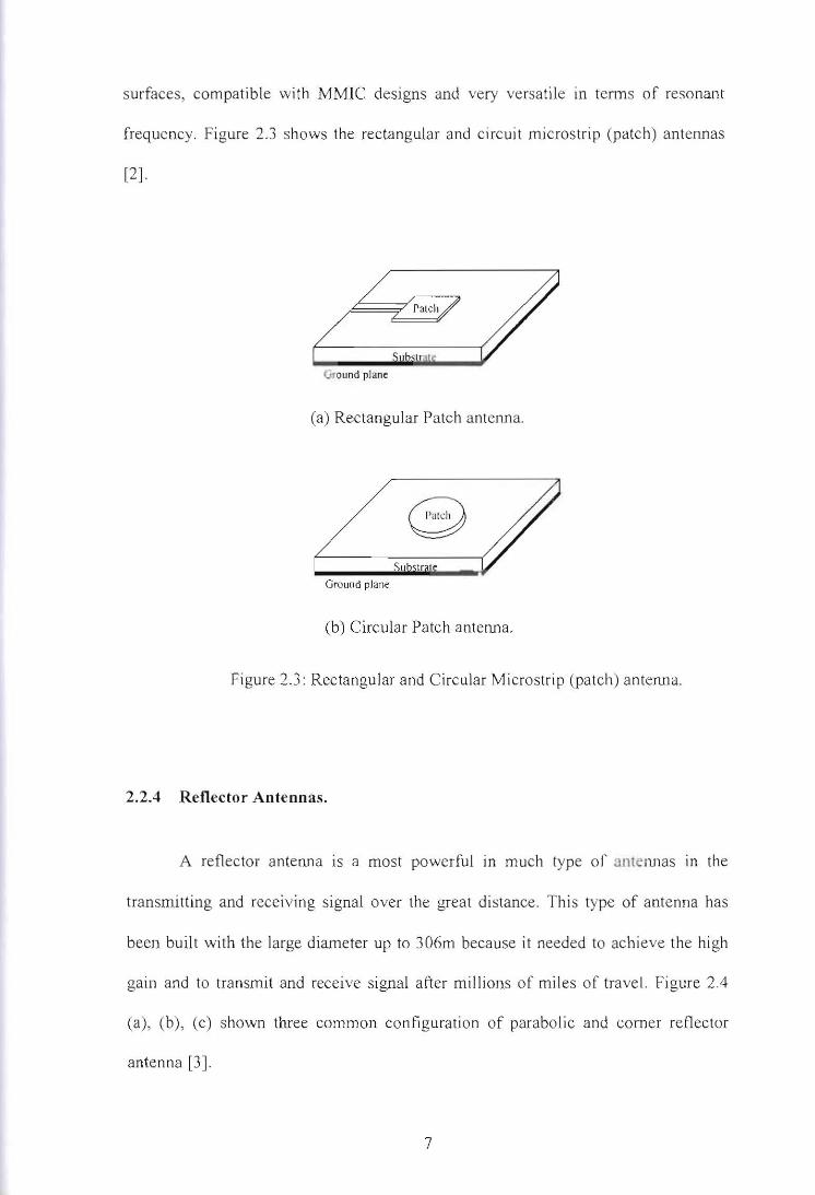
![Electrically Small Antenna Design - ITS Small Antenna Design ... Example : microstrip patch antenna Ground plane ... Bandwidth [MHz] relative patch size f r =1 GHz](https://img.pdfslide.us/doc/110x75/5aa70bfa7f8b9a6d5a8bcb7d/electrically-small-antenna-design-its-small-antenna-design-example-microstrip.jpg)