Embed Size (px)
Citation preview
International Journal of Science and Research (IJSR) ISSN (Online): 2319-7064
Index Copernicus Value (2013): 6.14 | Impact Factor (2015): 6.391
Volume 5 Issue 5, May 2016
www.ijsr.net Licensed Under Creative Commons Attribution CC BY
Simulation of Elliptical Relay for Long
Transmission Line Protection using MATLAB
Software
Abhishek Bagh1, T. G. Arora
2
1, 2Shri Ramdeobaba College of Engineering and Management, Department of Electrical Engineering,
Ramdeo Tekdi, Gittikhadan, Katol Road, Nagpur, India
Abstract: Relays are a key device for protection of transmission lines. It isolates the faulty section of electrical power system from rest
of the power system so that the rest portion can function satisfactorily without any severe damage due to fault current. Power swings
occur frequently in long transmission lines. Hence for protection of long transmission line, a relay must be chosen so that it is least
affected by power swing. Also relay must operate fast to prevent damage and maintain the stability of the system. In classical relay
systems, the trip signal is generated after at least one AC cycle. Elliptical relay is least affected by power swings. The algorithm used for
the generation of trip signal in proposed method operates the relay within one AC cycle which is much faster than a classical relay
system. The simulation results are obtained for both classical relay and the relay system using this algorithm in MATLAB software.
This paper presents the modelling of elliptical relay using the classical algorithm and the proposed algorithm in MATLAB software.
The conic characteristics are simulated and results are verified in MATLAB software.
Keywords: Conic characteristics, microcontroller, power swing, sampling, transmission line angle
1. Introduction
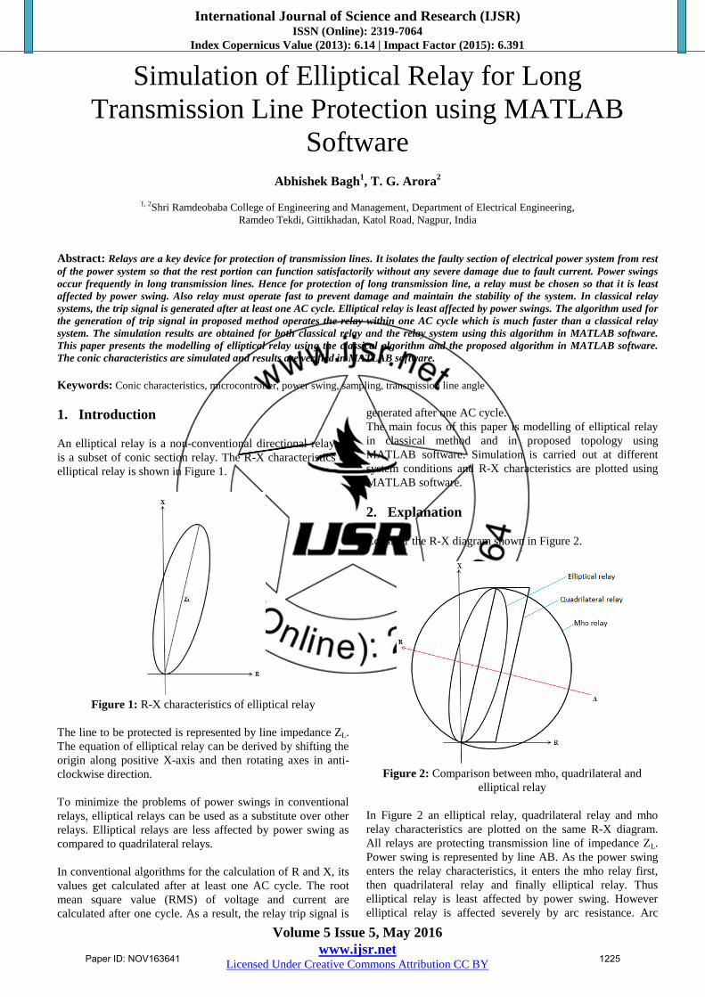
An elliptical relay is a non-conventional directional relay. It
is a subset of conic section relay. The R-X characteristics of
elliptical relay is shown in Figure 1.
Figure 1: R-X characteristics of elliptical relay
The line to be protected is represented by line impedance ZL.
The equation of elliptical relay can be derived by shifting the
origin along positive X-axis and then rotating axes in anti-
clockwise direction.
To minimize the problems of power swings in conventional
relays, elliptical relays can be used as a substitute over other
relays. Elliptical relays are less affected by power swing as
compared to quadrilateral relays.
In conventional algorithms for the calculation of R and X, its
values get calculated after at least one AC cycle. The root
mean square value (RMS) of voltage and current are
calculated after one cycle. As a result, the relay trip signal is
generated after one AC cycle.
The main focus of this paper is modelling of elliptical relay
in classical method and in proposed topology using
MATLAB software. Simulation is carried out at different
system conditions and R-X characteristics are plotted using
MATLAB software.
2. Explanation
Consider the R-X diagram shown in Figure 2.
Figure 2: Comparison between mho, quadrilateral and
elliptical relay
In Figure 2 an elliptical relay, quadrilateral relay and mho
relay characteristics are plotted on the same R-X diagram.
All relays are protecting transmission line of impedance ZL.
Power swing is represented by line AB. As the power swing
enters the relay characteristics, it enters the mho relay first,
then quadrilateral relay and finally elliptical relay. Thus
elliptical relay is least affected by power swing. However
elliptical relay is affected severely by arc resistance. Arc
Paper ID: NOV163641 1225

International Journal of Science and Research (IJSR) ISSN (Online): 2319-7064
Index Copernicus Value (2013): 6.14 | Impact Factor (2015): 6.391
Volume 5 Issue 5, May 2016
www.ijsr.net Licensed Under Creative Commons Attribution CC BY
resistance is negligible in long transmission lines as
compared to short and medium transmission lines. Thus
elliptical relay is suitable for protection of long transmission
lines where power swings occur frequently.
3. Algorithm for calculation of R and L
Transmission line is modelled as simple R-X circuit lumped
together. In discrete form, we can represent this as
dt
diLRiv n
nn (1)
dt
diLRiv n
nn
1
11
(2)
Also,
t
ii
dt
di nnn
2
11 (3)
t
ii
dt
di nnn
2
21 (4)
Where, t is time interval of sampling.
The R and L can be found out by
11
112
221
n
n
nn
nnnn
v
v
iit
ii
t
ii
DL
R (5)
Where,
1
112
22
n
nn
n
nn it
iii
t
iiD (6)
Thus by creating a window of four samples, we can calculate
the values of R and L. Thus the reactance of the relay is
given as
fLX 2 (7)
Thus the values of resistance and reactance are calculated.
4. Embedding elliptical relay characteristics
In X-Y frame, the equation of ellipse is given by
12
2
2
2
b
y
a
x (8)
Shifting the ellipse along positive Y-axis we get
1)(
2
2
2
2
b
ky
a
x (9)
Where k is offset along positive Y-axis. Now, rotating the
axes in anticlockwise direction we get
0
cos2sin22sin
sincoscossin
2222
2222
2222222222
baak
ykaxkaxyba
ybaxba
(10)
Where a and b are major and minor axes respectively.
is the angle shift between new and previous Y-axes.
5. Classical relay system topology
In classical relay system topology, the RMS values of
voltages and currents are calculated. The power factor of the
system is calculated. The resistance and reactance is the
calculated by
cosI
VR (11)
sinI
VX (12)
Where, is the phase shift between voltage and current.
Based on the values of resistance and reactance, the distance
relay operates.
6. Simulation of elliptical relay in classical
method using MATLAB software
To study the performance of elliptical relay in classical
method, simulation was performed in MATLAB software.
The parameters for line data are
Line impedance ZL = 1.08Ω
Transmission line angle β = 74.74 degrees
a =0.2
b = k = 0.54
= 90-β = 15.26 degrees
The simulation of elliptical relay in classical method is
shown in Figure 3 .The blocks are discussed below
6.1 Calculation of RMS values of voltage and current
The RMS value of voltage and current is calculated by the
RMS block. The frequency is set at 50 Hz.
6.2 Calculation of power factor
For the calculation of power factor, active and reactive power
is calculated. Thus,
Paper ID: NOV163641 1226

International Journal of Science and Research (IJSR) ISSN (Online): 2319-7064
Index Copernicus Value (2013): 6.14 | Impact Factor (2015): 6.391
Volume 5 Issue 5, May 2016
www.ijsr.net Licensed Under Creative Commons Attribution CC BY
Figure 3: Simulation of elliptical relay using classical method
22cos
QP
P
(13)
22 QP
QSin
(14)
Where, P and Q are active and reactive power respectively.
6.3 Calculation of resistance and reactance
For the calculation of resistance and reactance, impedance Z
is calculated. The impedance is calculated as
I
VZ (15)
The resistance and reactance is thus given by
cosZR (16)
sinZX (17)
Figure 4: Plot for RMS value of voltage
Figure 5: Plot for RMS value of current
Paper ID: NOV163641 1227

International Journal of Science and Research (IJSR) ISSN (Online): 2319-7064
Index Copernicus Value (2013): 6.14 | Impact Factor (2015): 6.391
Volume 5 Issue 5, May 2016
www.ijsr.net Licensed Under Creative Commons Attribution CC BY
Figure 6: Plot for resistance calculated by classical method
Figure 7: Plot for reactance calculated by classical method
Figure 8: Trip signal using classical method
6.4 Embedding elliptical relay characteristics
As the values of resistance and reactance are calculated, the
characteristics obtained from Equation 10 are incorporated.
Also the parameters of line data are incorporated.
6.5 Counter block
Usually the tripping signal is not applied instantaneously.
This is due to the transients that occur in the system. Hence a
counter block is added. If the count is more than the preset
value then the trip signal is initiated.
7. Simulation results of elliptical relay in
classical method using MATLAB software
In order to check when the true RMS value of the signal is
calculated, we simulated for voltage amplitude =1V and
current amplitude =1A. The current lags the voltage by 30
degrees. The results are shown in Figure 4 and Figure 5.
To check the trip condition, we considered the voltage
amplitude to be 0.186V and current amplitude to be 1A. The
current lags voltage by 30 degrees. This condition is just
inside the trip region of the relay R-X characteristics. The
calculated value of R and X is shown in Figure 6 and Figure
7 respectively. The trip signal is shown in Figure 8.
Paper ID: NOV163641 1228

International Journal of Science and Research (IJSR) ISSN (Online): 2319-7064
Index Copernicus Value (2013): 6.14 | Impact Factor (2015): 6.391
Volume 5 Issue 5, May 2016
www.ijsr.net Licensed Under Creative Commons Attribution CC BY
8. Analysis and explanation of results for
simulation in classical method
From Figure 4 and Figure 5 we clearly see that the RMS
values of voltage and current is calculated after one cycle.
Figure 8 shows that the trip signal is generated reliably after
one AC cycle. The trip signal before 0.02 seconds is because
wrong values of RMS voltage and current (true RMS values
are obtained after one AC cycle). As a result, the true value
of resistance and reactance is calculated after one AC cycle.
Hence in classical relay system, the trip signal and the
decision making of relay is done after one AC cycle.
9. Simulation of elliptical relay in proposed
topology using MATLAB software
To study the performance of elliptical relay, simulation was
performed in MATLAB software using this technique. The
test was carried out under various conditions and results were
obtained. The supply frequency is 50 Hz and the sampling
frequency is 5 KHz. That means there are 100 samples in one
AC cycle. The simulation of relay in proposed method is
shown in Figure 9.
Figure 9: Simulation of elliptical relay by proposed method
9.1 Sampling
Sampling is done using sample and hold circuit. The clock
decides the frequency at which sampling is to be done. Using
delays, four samples are obtained for the calculation of
resistance and inductance.
9.2 Calculation of resistance and inductance
Using delay, the values of four samples is obtained. The four
samples of voltage and current thus obtained are used to
calculate the value of resistance and reactance. The sampling
frequency is 5 KHz. Hence, ∆t = 0.2ms. Thus reactance can
be obtained.
9.3 Embedding elliptical relay characteristics
Since resistance and reactance are calculated, the
characteristics obtained from Equation. 10 are incorporated.
The transmission line angle β is given by
2
(18)
9.4 Subsystem
In order to distinguish between swing and trip signal, a
subsystem is made. When swing is high and trip is low then
system is said to be in transient state. By using K-map, we
get the condition as S anded with negation of T, where S is
swing signal and T is trip signal. The subsystem is shown in
Figure 10.
Figure 10: Subsystem
Paper ID: NOV163641 1229

International Journal of Science and Research (IJSR) ISSN (Online): 2319-7064
Index Copernicus Value (2013): 6.14 | Impact Factor (2015): 6.391
Volume 5 Issue 5, May 2016
www.ijsr.net Licensed Under Creative Commons Attribution CC BY
Figure 11: Sampled values of voltages (Voltage amplitude=1 V)
Figure 12: Sampled values of currents (Current amplitude=1 A) phase shifted by 30 degrees
Figure 13: Signals of swing and trip
5.5 Counter block
To add delay for the tripping signal, counter block is added.
The counter block resets if the transient disappears before the
counter initializes the trip signal.
10. Simulation results of elliptical relay for the
proposed topology using MATLAB software
The sampled waveform for voltage amplitude of 1V and
current amplitude of 1A along with delays is shown in Figure
11 and Figure 12 (Phase shift = 30 degrees). V1, V2, V3, V4
are sampled values of voltage whereas I1, I2, I3, I4 are
sampled values of current. Table 1 and 2 shows the trip
signals obtained for currents of 1 A and 1.5 A respectively.
The signal for swing and trip is shown in Figure 13.
Paper ID: NOV163641 1230

International Journal of Science and Research (IJSR) ISSN (Online): 2319-7064
Index Copernicus Value (2013): 6.14 | Impact Factor (2015): 6.391
Volume 5 Issue 5, May 2016
www.ijsr.net Licensed Under Creative Commons Attribution CC BY
Table 1: Simulation results for I = 1A Phase (rad) Current (A) Voltage (V) R X
0 1 0.0414 0.0414 0
0.157 1 0.0712 0.0703 0.0111
0.314 1 0.1096 0.1042 0.0338
0.471 1 0.1632 0.1454 0.0740
0.628 1 0.2429 0.1966 0.1427
0.785 1 0.3676 0.2600 0.2598
0.942 1 0.5638 0.3316 0.4559
1.099 1 0.8378 0.3807 0.7463
1.256 1 1.0630 0.3291 1.0107
1.413 1 0.9997 0.1571 0.9873
1.57 1 0.7270 0.0005 0.7270
1.9188 1 0.2854 -0.0973 0.2683
2.0933 1 0.1825 -0.0911 0.1582
2.2677 1 0.1175 -0.0754 0.0901
2.4422 1 0.0732 -0.0560 0.0471
2.6166 1 0.0401 -0.0347 0.0201
2.7911 1 0.0125 -0.0117 0.0042
2.9655 1 -0.0135 0.0132 -0.0023
Table 2: Simulation results for I = 1.5A Phase (rad) Current (A) Voltage (V) R X
0 1.5 0.0621 0.0414 0
0.157 1.5 0.1068 0.0703 0.0111
0.314 1.5 0.1644 0.1042 0.0338
0.471 1.5 0.2448 0.1454 0.0740
0.628 1.5 0.3644 0.1966 0.1427
0.785 1.5 0.5514 0.2600 0.2598
0.942 1.5 0.8457 0.3316 0.4559
1.099 1.5 1.2568 0.3807 0.7463
1.256 1.5 1.5945 0.3291 1.0107
1.413 1.5 1.4996 0.1571 0.9873
1.57 1.5 1.0905 0.0005 0.7270
1.9188 1.5 0.4282 -0.0973 0.2683
2.0933 1.5 0.2738 -0.0911 0.1582
2.2677 1.5 0.1763 -0.0754 0.0901
2.4422 1.5 0.1099 -0.0560 0.0471
2.6166 1.5 0.0601 -0.0347 0.0201
2.7911 1.5 0.0187 -0.0117 0.0042
2.9655 1.5 -0.0201 0.0132 -0.0023
Figure 14: R-X diagram obtained using for I = 1.5 A using
MATLAB software
11. Analysis and explanation of results for
simulation of elliptical relay using proposed
topology
Since the resistance and reactance is calculated by using four
samples, the trip signal is generated before one AC cycle.
This can be verified in Figure 13 in which trip signal is
generated in 0.403ms. The counter count can be increased to
increase the delay of tripping signal. The elliptical relay
characteristics is obtained and verified as shown in Figure 14.
12. Advantages of this method
1) Since this technique uses four samples for the calculation
of Rand X, the relay operation is very fast.
2) Compatible to the microcontroller.
3) Since it can be used in microcontroller, the VA burden of
CTs and PTs are reduced. Thus the number of
components required is reduced.
4) Flexibility is increased.
5) Since this technique is compatible to microcontroller,
operational logic can be used to control the operation of
transmission lines.
13. Conclusion
Elliptical relay is least affected by power swing. The
proposed algorithm is much faster than the classical method.
It takes only four samples for its operation. Hence it is very
fast to operate as compared to other elliptical relay. Thus
elliptical relay if used by this technique will generate trip
signal in very short time which is useful for protection of
long transmission lines.
References
[1] Y.G Paithankar and S.R Bhide, Fundamentals of power
system protection, Prentice Hall of India Private
Limited, 2003.
[2] Badri Ram and D.N. Vishwakarma, Power System
Protection and Switchgear, McGraw Hill Education
(India) Private Limited, 2013.
[3] P. Kundur, Power System Stability and Control,
McGraw Hill Education (India) Private Limited, 2013.
[4] Ramakant A. Gayakawad, Phi Learning private Limited,
2012.
Author Profile
Abhishek Bagh received the Bachelor degree in
Electrical Engineering from Shri Ramceobaba College
of Engineering and Management in 2014. He is
currently pursuing M. Tech in Shri Ramdeobaba
College of Engineering and Management
T.G Arora was born in Nagpur, India, on June 20,
1961. He received the B.E. degree in Electrical
Engineering from the Government College of
Engineering, Amravati, Maharashtra, India, in 1983
Paper ID: NOV163641 1231

International Journal of Science and Research (IJSR) ISSN (Online): 2319-7064
Index Copernicus Value (2013): 6.14 | Impact Factor (2015): 6.391
Volume 5 Issue 5, May 2016
www.ijsr.net Licensed Under Creative Commons Attribution CC BY
and M.Tech. degree from Visvesvaraya Regional College of
Engineering, Nagpur, Maharashtra, India, in 1985. He has
submitted the Ph.D. thesis in the area of High Voltage Engineering
in Rastrasant Tukadoji Maharaj Nagpur University, Nagpur,
Maharashtra, India. From 1985 to 1986, he was a Research
Assistant with the Visvesvaraya Regional College of Engineering,
Nagpur. Since 1986, he is an Associate Professor in Electrical
Engineering Department of Shri Ramdeobaba College of
Engineering and Management, Nagpur, India. He has published 10
articles. His research interests include insulation breakdown and
discharges under non-sinusoidal waveforms and power system
protection. T. G. Arora is the fellow of Institution of Engineers
(India) and life member of Indian Society for Technical Education.
Paper ID: NOV163641 1232