Embed Size (px)
DESCRIPTION
Introduction to the LCC –Institute of Carbon Composite•Process Simulation –Why?•Simulation of the•Draping Process•Braiding Process•Automated Fiber Placement (AFP) Process•Simulation of the Liquid Composite Moulding(LCM) Process•Curing Simulation – Process Induced Deformation (PID)•Simulation Platform•Conclusions and Outlook
Citation preview

Simulation of Draping, Infiltration and Curing of Composites
Dr. R. M. Hinterhölzl, FACC Technical Colloquium “Advances in Composites”
5./6.7.2012, Salzburg / Austria

• Introduction to the LCC –Institute of Carbon Composite
• Process Simulation –Why?
• Simulation of the
• Draping Process
• Braiding Process
• Automated Fiber Placement (AFP) Process
• Simulation of the Liquid Composite Moulding(LCM) Process
• Curing Simulation – Process Induced Deformation (PID)
• Simulation Platform
• Conclusions and Outlook
5./6.7.2012 2
Overview
Simulation of Draping, Infiltration and Curing of Composites

Institute for Carbon Composites
5./6.7.2012 3
• Founded in Mai 2009 financially supported by the SGL Carbon Group • Professor Dr.-Ing. Klaus Drechsler • 52 researchers • 2 team assistants • 5 Technical Employees
Main Research Topics:
Simulation of Draping, Infiltration and Curing of Composites

Industrial Partners
5./6.7.2012 4
Lehrstuhl für Carbon Composites
Simulation of Draping, Infiltration and Curing of Composites

5./6.7.2012 5
• Aviation industry
approx. 50% of the structure are made out of Composite: fuselage, frames, stringers, skins,…
High volume
Bigger parts
Need for process optimization
Need for automation
• Automobile industry
Serial production with very high volume, short cycle time, robust processes
further and new developments and optimization of manufacturing processes
From hand lay up to (partly) automated serial production
Automation Shorter cycle times Process reliability Short design and development time
Simulation of Draping, Infiltration and Curing of Composites
Manufacturing Process Simulation – Why?

5./6.7.2012 6
semi-finished part
preforming (here: draping)
curing
matrix-injection
component
Simulation of composites
Semi-finished part structure: micro-/mesomechanics
FE draping simulation
LCM simulation: flow front
Structural component simulation
Curing- and distortion simulation
[FACC AG]
Simulation of Draping, Infiltration and Curing of Composites

Draping Simulation
5./6.7.2012 7 Simulation of Draping, Infiltration and Curing of Composites

• Part design (design to process) – Prediction of fiber alignment – Prediction of fiber volume fraction – …
• Process development / optimization – Drapeability inspection (feasibility study) – Prediction of draping defects – Geometry and alignment of the flat preform – …
• Embedding in process simulation platform – Basis for: – LCM simulation – Curing and PID simulation – Structural simulation
5./6.7.2012
Goals of Draping Simulation
lay-up of the preform
tool preform
Forming (draping) in required shape
Airbus A380 – Pressure Bulkhead
8 Simulation of Draping, Infiltration and Curing of Composites

• Textiles – woven, Non-Crimp Fabrics (NCF), UD, etc. – dry or pre-impregnated
• Deformation modes
• Defects
5./6.7.2012
Requirements for Draping Simulation
plain weave twill weave NCF
Shear Intra-ply Motion
Wrinkling / Folds
Inter-ply Motion Elongation Bending
Loops Gaps / Voids Fiber Pull-Out Damage of Stitching
9 Simulation of Draping, Infiltration and Curing of Composites

Finite Element Approach
• modeling of the preform on ply-level with shell elements
• simulation of the draping process and the tools
• consideration of forces, friction, velocities, etc.
• prediction of deformation modes and defects in the preforms
Kinematic Approach
• pin-joint method [Mack 1950]
• purely geometrical approach
• computation of the fiber direction
• direct cut geometry generation
Numerical Approaches for Draping Simulation
5./6.7.2012
level o
f detail
L1 L2
P
shear
bending elongation
10 Simulation of Draping, Infiltration and Curing of Composites

Kinematic Approach
+ fast & easy to use + many software available + good interface to structural analysis - no material behavior - no process influence - poor results for complex shapes
Comparison of the Different Approaches
Finite Element Approach + accurate results even for complex shapes + accounts for material and process influence + prediction of draping defects possible (wrinkles, gaps, etc.) - higher computational effort - material testing required
Catia CPD (Kinematic Simulation)
Experiment PAM-FORM (FE Simulation)
5./6.7.2012 11 Simulation of Draping, Infiltration and Curing of Composites

Simulation Procedure
Validation
Process Simulation
Parameter Determination
Material characterization (simulation of the material behavior)
• Picture Frame Test
• …
Validation on test geometry
• Hemisphere
• Double Dome
• …
Process simulation (design and optimization)
• Diaphragm draping
• Drape forming
• Hand lay-up
• …
Saertex
ECD
5./6.7.2012 Kap.-12 Simulation of Draping, Infiltration and Curing of Composites

Prediction of • Draping defects
• Positioning of darts and stitching
• Flat pattern
• Material and process characteristics
• …
To be used in • Part design / development
• Process development or optimization
• Composite process simulation platform
• …
5./6.7.2012
Profits of Draping Simulation
13 Simulation of Draping, Infiltration and Curing of Composites

Simulation of the Automated Fiber Placement Process (AFP)
5./6.7.2012 14 Simulation of Draping, Infiltration and Curing of Composites
5./6.7.2012 15
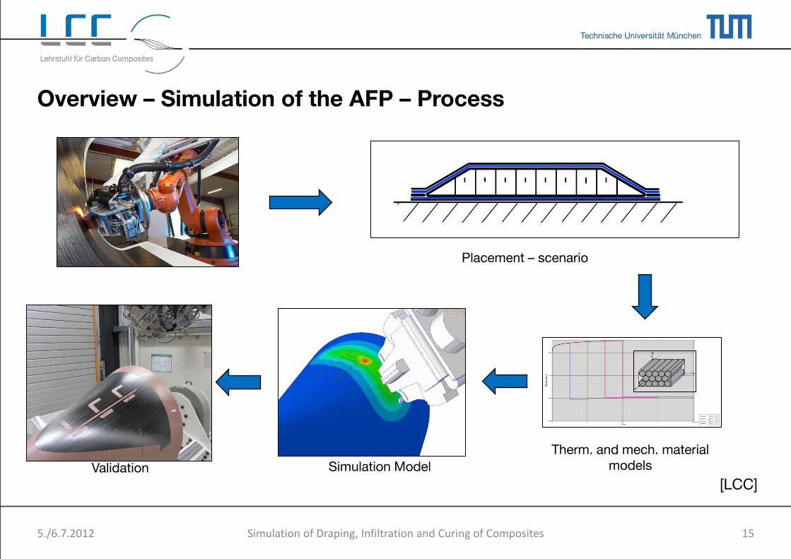
Overview – Simulation of the AFP – Process
Placement – scenario
Therm. and mech. material models Simulation Model Validation
[LCC]
Simulation of Draping, Infiltration and Curing of Composites

Research Activities at the LCC
5./6.7.2012 16
0
0.05
0.1
0.15
0.2
0.25
0.3
0.35
0.4
ε[Δ
l / l]
Zeit [s]
1D – Simulation: • Calculation of the time-dependent
mech. compaction behaviour • Simulation of the transient heat
transfer
2D – Simulation: • Prediction of the mech. and therm. behaviour
of the process • Simulation of bridging of the tape • Modeling of tack
3D – Simulation: • Mech. placement on complex geometry
possible • Prediction of the complete thermal history
of the placement process
Simulation of Draping, Infiltration and Curing of Composites

• Gap- / Overlap detection
• Compaction / Debulking
• Bridging
• Complete temperature distribution
AFP – Process Simulation: Examples
5./6.7.2012 17
Fig. 1: Gap in Simulation
Fig. 3: Surface temperature distribution
Fig. 2: Compaction behaviour of a Slit-Tape
Simulation of Draping, Infiltration and Curing of Composites

• Prediction of Bridging and Sliding
• Prediction of Gaps and Overlaps
• Simulation of the complete heat transfer
• Simulation of the Compaction behaviour results in a debulking prediction
• Optimization of all Process parameters, e.g. Compaction Force, Heat Output, Process Speed
• Linkage between all problems to find a reliable process window
Benefits of the AFP Process Simulation
5./6.7.2012 18
Fig. 1: Sim. Bridging
Fig. 2: Contact pressure and peel-force
Fig. 3: Thermodynamic simulation of a generic AFP – Process
Simulation of Draping, Infiltration and Curing of Composites

5./6.7.2012 19
Braiding Process Simulation
Simulation of Draping, Infiltration and Curing of Composites

• High volume production of composites – short cycle time, automated and robust processes
• Braiding technology – Preforming of fibers and subsequent resin infusion
– High degree of automation possible
• Overbraiding process – Bobbin carrier -> interlacing yarn pattern
– Braid deposits on mandrel
• Process offers high flexibility – Mandrel shape defines contour of stucture
– Braiding angle, areal weight, etc.
Braiding process – Introduction
Braiding machine and principle of braiding
5./6.7.2012 20 Simulation of Draping, Infiltration and Curing of Composites

Braided composites:
• Input: – production parameters and mandrel geometry
• Output: – Undulation, intersection of yarns, variable braiding angle
variable material properties (stiffness and strength)
Analysis requirments:
• Process influence on yarn architecture
• Yarn architecture influence on material properties: – Elastic behavior
– Failure behavior
Braiding process – Analysis of braided Composites
Variation of Braiding Angle on Component [FACC AG]
5./6.7.2012 21 Simulation of Draping, Infiltration and Curing of Composites
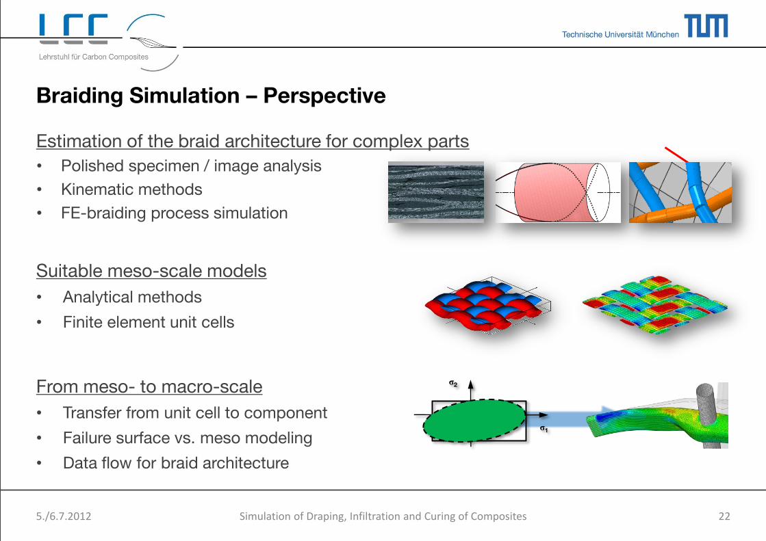
Estimation of the braid architecture for complex parts
• Polished specimen / image analysis
• Kinematic methods
• FE-braiding process simulation
Suitable meso-scale models
• Analytical methods
• Finite element unit cells
From meso- to macro-scale
• Transfer from unit cell to component
• Failure surface vs. meso modeling
• Data flow for braid architecture
Braiding Simulation – Perspective
σ2
σ1
5./6.7.2012 22 Simulation of Draping, Infiltration and Curing of Composites

FE Braiding Process Simulation
Yarns
• Explicit FE Model using Abaqus/Explicit
• Yarns:
– Truss elements
– Pretension
– BCs according to braiding configuration
• Yarn-yarn interaction
– Contact with friction
• Mandrel
– BC for motion calculated automatically
– No limitations in shape
• Model generation
– Python scripting inside Abaqus
– Mandrel movement calculated using MATLAB script
Springs: pretension
Braiding ring
Mandrel
5./6.7.2012 23 Simulation of Draping, Infiltration and Curing of Composites

Biaxial full braiding configuration:
FE Braiding Process Simulation
Yarn architecture: inner bend
Yarn architecture: outer bend
Yarn architecture: straight cylinder
5./6.7.2012 24 Simulation of Draping, Infiltration and Curing of Composites

5./6.7.2012 25
Simulation of Liquid Composite Moulding (LCM)
processes
Simulation of Draping, Infiltration and Curing of Composites
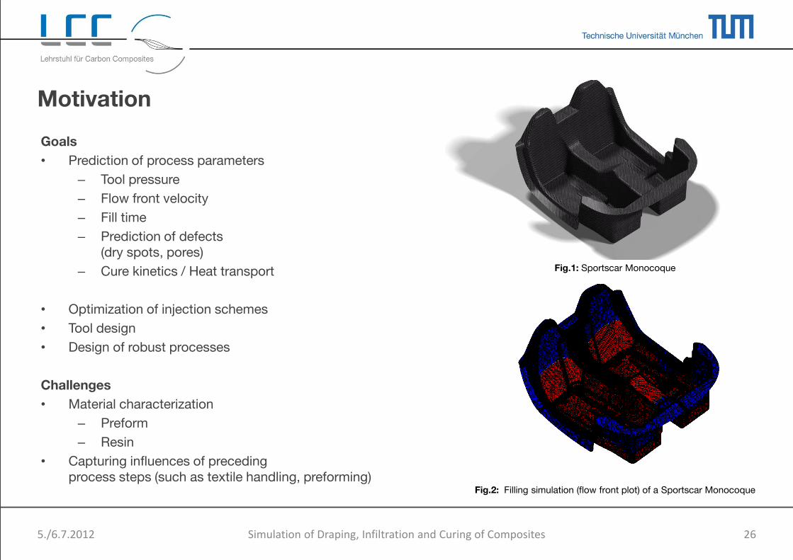
Goals
• Prediction of process parameters
– Tool pressure
– Flow front velocity
– Fill time
– Prediction of defects (dry spots, pores)
– Cure kinetics / Heat transport
• Optimization of injection schemes
• Tool design
• Design of robust processes
Challenges
• Material characterization
– Preform
– Resin
• Capturing influences of preceding process steps (such as textile handling, preforming)
Motivation
5./6.7.2012 26
Fig.1: Sportscar Monocoque
Fig.2: Filling simulation (flow front plot) of a Sportscar Monocoque
Simulation of Draping, Infiltration and Curing of Composites

5./6.7.2012 27
• Tool design – Securing expensive investments for RTM tools
e.g. reducing the risk of dry spots
• Estimation of process parameters Various geometries and fiber architectures
Prediction of
• process time
• flow front propagation
• imperfections
• Design of robust processes Simulating variations within the process chain
• Semi-finished product
• Preforming and Handling
• LCM process
Definition of Quality Gates for each step
Less scrap parts and more reproducible output
Profits of LCM Simulation
Fig.: RTM tool (source: Eurocopter)
Simulation of Draping, Infiltration and Curing of Composites

Physics of LCM Processes
• Flow processes in porous media can be described by the Navier-Stokes equation
𝜌𝜕𝑣
𝜕𝑡= −𝛻𝑃 + 𝛻 ∙ 𝑇 + 𝑓
• By homegenization of the media (e.g. by volume averaging) and introducing some assumptions the flow can be described by Darcy‘s law
𝑣 =𝐾
𝜇𝛻𝑃 − 𝜌𝑔 ≈
𝐾
𝜇𝛻𝑃
• Darcy‘s law relates the flow front velocity 𝑣
to the applied pressure gradient 𝛻𝑃 with the proportionality constants permeability 𝐾
and viscosity 𝜇.
• Permeabiliy is a material parameter of the fiber preform
• Material
• Layup
• Fiber orientation
• Compaction state
5./6.7.2012 28
Fig.1: Illustration of flow fronts (Real vs. Darcy) within an textile preform
Tab.1: Summary of assumptions for validity of Darcy’s law
• Newtonian Fluid • Constant Viscosity • Homogeneous, Inelastic Porous Medium • Neglecting of Gravity and Capillary Forces • Low Flow Velocity (𝑅𝑒 < 1) • Saturated Flow • Neglecting Intra Yarn Flow
Simulation of Draping, Infiltration and Curing of Composites

𝐾∗ =
𝐾11 0 00 𝐾22 00 0 𝐾33
(lat.: permeare = ‚to pass‘)
Description
In the 3D case the permeability can be noted as a 2nd order tensor.
The tensor can be diagonalized with a rotation of the global coordinate system to a coordinate system spanned by the major permeabilities (cf. Eq.1).
Determination
• Experimental
• 1D-flow method
• Radial-flow method (2D)
• 3D-flow method
• Numerical
5./6.7.2012 29
Permeability Testing for LCM Processes
Fig.3: Off-plane test setup Fig.2: In-plane test setup
Fig.1: 3D permeability tensor
ln-Plane components / 2D tensor
Off-Plane component/ through thickness perm.
Simulation of Draping, Infiltration and Curing of Composites

Numerical Method - Overview
5./6.7.2012 30
„Grey Box“ Software Tool
(Matlab)
RTM Process Simulation (PAM-RTM)
Fabric Scan
Info
Material Card
Draping Simulation
Process Parameter
CAD
• Image Analysis • Textile Modeling • Permeability Calculation • Material Data
Fig.1: Fabric Scan Fig.2: Image Analysis Fig.3: Textile Model [WiseTex, KU Leuven]
Simulation of Draping, Infiltration and Curing of Composites

Current fields of research are
1. Permeability Prediction
• For Various Textile Types
• With Respect to Shear State and Fiber Volume Content
2. Numerical Permeability Prediction
• Efficient Determination of Parameters
• Modeling of a Representative Unit Cell
3. Characterization of Variability of Textile Preforms
• Development Testing Methods
• Process Simulation to assess impact on LCM process
4. Characterization of Complex Preforms
• Thick laminates
• Radius
• Butt-splice, Overlaps
5. LCM Simulation of parts
5./6.7.2012 31
Outlook
Fig.1: Complex RTM component [FACC AG]
Simulation of Draping, Infiltration and Curing of Composites

32 5./6.7.2012
Determination of Process Induced Deformations (PID) & Curing Simulation
Simulation of Draping, Infiltration and Curing of Composites

• Geometrical deviations of stiff structures
Additional rework effort and / or high mounting forces required
Expensive iterative tooling adaption
5./6.7.2012 33
Potential on Dimensional Control of Stiff Structures
Picture: DLR
Deformed frame after curing Magnification factor: 30
Deformed frame section Magnification factor: 30
Simulation of Draping, Infiltration and Curing of Composites

• primary:
• Determination of process induced deformations (dimensional accuracy)
• Evaluation of the effects of residual stress (structural analysis)
• secondary:
• process optimization (cycle time)
• process control (interaction between parallel simulation of physical curing process)
5./6.7.2012 34
Curing simulation - goals
Shrinkage Spring-In / Spring -
Back
Warpage
PID Fernlund et al, 2003
Svanberg, 2002 Twigg, 2001
Simulation of Draping, Infiltration and Curing of Composites

Methodologies for determination of process induced deformations (PID)
5./6.7.2012 35
Analytical: Estimation of deformation for simple geometries
Experimental: Iterative optimization of final part shape
Phenomenological: Summarization of different mechanisms with one actuating variable (enhanced CTE)
Curing simulation: Simulation of all relevant mechanisms (e.g. reaction kinetics, modulus development,…)
Increasing level of detail and modeling effort
Simulation of Draping, Infiltration and Curing of Composites

Process simulation including curing: application flow on the example COMPRO
5./6.7.2012 36
Thermo-chemical module • reaction kinetics • heat conduction
Flow Module • resin flow due to laminate compaction (viscosity, permeability) → variations in wall thickness and fiber volume content
Stress module • modulus development related to resin degree of cure, temperature • resin cure shrinkage and thermal expansion coefficients
Figure: Time-Temperature-Transition-(TTT) Diagram
Figure: modulus development
Figure: Experimental determination of effective HTC
Virtual autoclave • heat transfer autoclave gas → part-tooling-assembly • feedback control autoclave
Figure: Force-Displacement-Diagram Fiber Bed Compaction
control routine – status variables ( ,T)
COMPRO is a commercial composite processing software: Convergent Manufacturing Technologies, Vancouver, Canada
Johnston A., Hubert P., 1996
Simulation of Draping, Infiltration and Curing of Composites
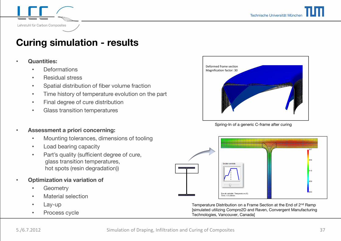
• Quantities:
• Deformations
• Residual stress
• Spatial distribution of fiber volume fraction
• Time history of temperature evolution on the part
• Final degree of cure distribution
• Glass transition temperatures
• Assessment a priori concerning:
• Mounting tolerances, dimensions of tooling
• Load bearing capacity
• Part’s quality (sufficient degree of cure, glass transition temperatures, hot spots (resin degradation))
• Optimization via variation of
• Geometry
• Material selection
• Lay-up
• Process cycle
5./6.7.2012 37
Curing simulation - results
Spring-In of a generic C-frame after curing
Deformed frame section Magnification factor: 30
Temperature Distribution on a Frame Section at the End of 2nd Ramp [simulated utilizing Compro2D and Raven, Convergent Manufacturing Technologies, Vancouver, Canada]
Simulation of Draping, Infiltration and Curing of Composites

Profits of Curing and PID Simulation
5./6.7.2012 38
• Production support - defining process boundary conditions for a robust design
– curing of thick walled components → identification and elimination of hot spots
– high cost savings on reduction of tool adoption
– reduction of rework due to geometrical misfit (especially stiff structures)
– reduced risk for the manufacturing of big components und small highly integral RTM parts
• Effective PID determination by tailoring to particular assembly needs
– appropriate model detail
– relevant material characterization
– adapted analysis approach
• Cure cycle time optimization (where no stringent cycle predetermined)
Simulation of Draping, Infiltration and Curing of Composites

5./6.7.2012 39
Determination of PID – State of the Art on A Simple Example
Analytical Spring-In Determination Utilizing Lamina (1) and Laminate (2) Homogenization (e.g. [Radford, 1988])
Numerical Distortion Analysis Utilizing Sequential Thermo-Chemical (1) and Mechanical Analysis (2) [simulated utilizing Compro CCA, Convergent Manufacturing Technologies, Vancouver, Canada]
+ =
T
I αI, ϕI
αT, ϕT (1) (2)
Nodal temperatures, (1) Displacements, (2)
Temperature and Degree of cure history
Simulation of Draping, Infiltration and Curing of Composites

5./6.7.2012 40
Activities on PID Determination
Calibration Application Characterization
Overall goal: effective application of process simulation for PID determination
• Resin cure kinetics • Glass transition • Modulus development • CTE • …
• Interaction calibration • Shear layer modulus • Cohesive modeling
• Determination of enhanced CTEs for different setups (e.g. sandwich)
• Applicability of enhanced CTE
• Boundary condition characterization
• Sensitivity analyses
Simulation of Draping, Infiltration and Curing of Composites

41 5./6.7.2012
Simulation Platform
Simulation of Draping, Infiltration and Curing of Composites

Simulation Platform
5./6.7.2012 Simulation of Draping, Infiltration and Curing of Composites 42
Material Modelling
Draping simulation
LCM simulation
Curing- and distortion simulation
structural component simulation
[FACC AG]

5./6.7.2012 Simulation of Draping, Infiltration and Curing of Composites 43
Material Modelling LCM simulation
Curing- and distortion simulation
Structural component simulation
CATIA CPD/AFM PAM-FORM PAM-Quickform ABAQUS
Draping simulation
ABAQUS NASTRAN
ABAQUS NASTRAN COMPRO (CMT)
PAM-RTM RTM Worx
Common Data XML Format
Mapping Tool
Material Database
Wrapping Tool
WiseTex
Simulation Platform

Draping Simulation for Process Simulation Platform
5./6.7.2012 Simulation of Draping, Infiltration and Curing of Composites 44
• Draping simulation as a part of the process simulation platform for composites
– Provide data for subsequent simulations
– Supply of: fiber alignment, shear angles, thickness, etc.
• Draping results are combined to a continuous simulation tool chain and connected to a structure simulation
Draping
Infiltration
Curing
Structure

5./6.7.2012 45
Process Simulation Platform - Example
Preforming
• Draping, Braiding, Filament winding, …
• Simulation of the preform process
Preform Characterization
• Experimental
• Numerical
LCM-Simulation
• Tool design, Process time prediction (Flow front velocity, pressure distribution)
• Process optimization
• Curing simulation (for PID investigations)
Simulation of Draping, Infiltration and Curing of Composites

• Close interaction in-between production and simulation (process simulation and structural simulation) is strongly required
• Process simulation supports the development and optimization of the manufacturing process (cycle time, process robustness, etc.)
• Simulation of individual process steps (draping, LCM, curing,…) and their dependency on each other is possible
• Process simulation supports the part design
fibre orientation defines stiffness and strength of the part
• Goal is the simulation of the whole composite manufacturing process
5./6.7.2012 46
Conclusion
Simulation of Draping, Infiltration and Curing of Composites

Outlook
5./6.7.2012 Kap.-47
Composite Process-Simulation
OEM
Engineering Office
Test Labaratory
LCC
Software
Software Houses
Customers – Application Centers
Production Engineering Supplier
Scientific Backbone
LCC
Simulation of Draping, Infiltration and Curing of Composites

• FACC AG / PCCL - COMET-K1 projects IV-3.04 and 3.S2
• Eurocopter Deutschland GmbH – Funded research project HELIPLACE
• Eurocopter Deutschland GmbH - LUFO IV: CompTAB - Composite Tool Chain and Enhancement to As Built
• Eurocopter Deutschland GmbH - Funded research project Vi-TECH
• EADS-IW - LUFO IV: CompTAB/ ITComp: Integrated Toolchain for Simulation of Composites
• Audi AG
• General Electric (GE)
• BMBF Project MAIdesign within cluster of excellence MAICarbon
5./6.7.2012 48
Acknowledgements
Simulation of Draping, Infiltration and Curing of Composites

5./6.7.2012 49
Thank you for your attention!
semi-finished part
preforming (here: draping)
curing
matrix-injection
component
Semi-finished part structure: micro-/mesomechanics
FE draping simulation
LCM simulation: flow front
Structural component simulation
Curing- and distortion simulation
[FACC AG]
Simulation of Draping, Infiltration and Curing of Composites