Embed Size (px)
Citation preview
SIMULATION OF CARBON DIOXIDE -
MONOETHANOLAMINE - WATER SYSTEM USING
EQUILIBRIUM APPROACH
A THESIS SUBMITTED IN PARTIAL FULFILLMENT
OF THE REQUIREMENTS FOR THE DEGREE OF
Bachelor of Technology
In
Chemical Engineering
Submitted by:
Devesh Prasad Mishra
ROLL NUMBER- 110CH0393
Under the guidance of:
Prof Madhushree Kundu
Department Of Chemical Engineering
National Institute Of Technology
Rourkela-769008
2013-2014
CERTIFICATE
This is to certify that the thesis entitled, “SIMULATION OF CARBON DIOXIDE -
MONOETHANOLAMINE - WATER SYSTEM USING EQUILIBRIUM APPROACH”,
submitted by Mr. Devesh Prasad Mishra , Roll No. 110CH0393 in partial fulfillment of the
requirements for the award of degree of Bachelor of Technology in Chemical Engineering at
National Institute of Technology, Rourkela is an authentic work carried out by him under my
supervision and guidance.
To the best of my knowledge, the matter embodied in the report has not been submitted to any other
University / Institute for the award of any Degree or Diploma
Date: Dr. Madhushree Kundu
Place: Rourkela Department Of Chemical Engineering
National Institute of Technology,
Rourkela-769008
ACKNOWLEDGEMENT
I would like to convey my sincere gratitude to my project guide Dr.Madhushree Kundu, for her
invaluable suggestions, guidance, encouragement and help at various stages of the this project.
I would also like thank Dr. R. K. Singh, HOD, as well as the Project Coordinator, Department of
Chemical Engineering, National Institute of Technology, Rourkela, for his valuable motivation
and timely suggestions during the entire duration of my project work, without which this work
would not have been possible.
Date: Devesh Prasad Mishra
Place: Rourkela Roll No-110CH0393
Department Of Chemical Engineering
National Institute Of Technology,
Rourkela-769008
ABSTRACT
Carbon Dioxide is a greenhouse gas and has been identified as the prime source of global
warming and climate changes. So the major challenge ahead of us is the capture and removal of
CO2. Though there are different methods and technologies available, the most efficient method
is the use of an absorption/stripping process with a chemical solvent for absorption. Various
solvent have been tried, but aqueous monoethanolamine remains the most common and popular
solvent.
This thesis focuses on the development of a comprehensive flowsheet based on the
thermodynamic model which assumes the overall process to be at equilibrium. The ASPEN
PLUS software was used for developing and simulating the problem. The Electrolyte–NRTL
model was chosen as the base method with ensured the use of predefined physical properties,
thermodynamics and kinetics for the simulation of the process. Once the simulation is over and it
properly converges giving an acceptable capture percentage , sensitivity analysis were carried
out to study and get an rough idea about the nature and extent of the effect of different
parameters on the reboiler duty or energy requirement and other properties like amine flow rate .
The simulation based on thermodynamic model is the stepping stone for the more complex and
tedious rate based studies as its gives us an estimate of different properties and constraints.
CONTENTS
CERTIFICATE………………………………………………………………………... i
ACKNOWLEDGEMENT ……………………………………………………………. ii
ABSTRACT……………………………………………………………………………. iii
LIST OF FIGURES…………………………………………………………………… vi
LIST OF TABLES…………………………………………………………………….. vii
NOMENCLATURE…………………………………………………………………… viii
CHAPTER 1: INTRODUCTION.................................................................................. 1
1.1 Need for the absorption of CO2.......................................................................... . 1
1.2 Overview of CO2 Capture System...................................................................... 1
1.2.1 Post-combustion capture............................................................................... 1
1.2.1.1 Chemical absorption................................................................. 3
1.2.2 Oxyfuel Combustion……………………………………………………… 4
1.2.3 Precombustion capture.................................................................................. 4
1.3 Objective of the thesis ……………………………………………………....... 6
1.4 Scope of the thesis...…………………………………………………………… 6
1.5 Outline of the thesis …………………………………………………………… 6
CHAPTER 2: LITERATURE REVIEW……………………….…….......................... 8
2.1 Solvents Used For CO2 Capture ....................................................................... 8
2.2
Alkanolamines And Its Reaction With CO2....................................................... 8
2.2.1 Zwitterion Mechanism.................................................................................. 8
2.2.2 Termolecular Mechanism.............................................................................. 9
2.3 Modeling of CO2-MEA-Water System………………………………………. 9
CHAPTER 3:-MONOETHANOLAMINE SYSTEM……………………………… 11
3.1 Process Description……………………………………………………………. 11
3.1.1 Flue Gas Cooling And Compression……………………………….......... 12

3.1.2 Absorption Of CO2 And Regeneration Of Solvent…………………….... 13
3.1.3 CO2 Compression………………………………………………………... 14
3.2 Chemistry of the MEA system……………………………………………...... 14
3.3 Thermochemistry in the MEA system……………………………………….. 15
CHAPTER-4 THERMODYNAMIC AND RATE MODEL……………………….. 16
4.1 Thermodynamic Model……………………………………………………….. 16
4.1.1 Electrolyte NRTL Model………………………………………………… 16
4.1.2 Solution Chemistry And Equilibrium Governing Equations…………….. 17
4.2 Rate Model…………………………………………………………………….. 19
CHAPTER-5 SIMULATION ACCORDING TO THERMODYNAMIC MODEL.. 20
5.1 Steps Involved In Developing the Flowsheet ………………………………... 21
CHAPTER-6 RESULTS AND DISCUSSION………………………………………... 26
6.1 Effect of Lean Loading on L/G in absorber for 80 % Capture ……............. 26
6.2 Effect of L/G in Absorber on Reboiler Duty for 80 % Capture ……........... 28
6.3 Effect of Capture Percentage ………………………………………………… 29
6.4
Effect of Desorber pressure on Reboiler Duty and Temperature.................. 31
6.5 Effect of approach temperature on the Reboiler Duty …………….......…… 33
CHAPTER-7
7.1 CONCLUSION ……………………………………………………………….. 35
7.2 FUTURE COURSE OF WORK…………….................................................... 36
REFERENCE …………………………………………………………………………. 37
LIST OF FIGURES
Fig
no.
Name of figure
Page
no.
1.1
Schematic of post-combustion capture
02
1.2
Schematic of CO2 capture by chemical absorption process.
03
1.3
Schematic of Oxyfuel combustion
04
1.4
Schematic of precombustion decarbonization.
05
2.1
Zwitterion mechanism for carbamate formation
08
2.2
Termolecular mechanism for carbamate formation
09
3.1
Schematic of CO2 capture by use of MEA solvent
11
5.1
Process flow diagram of MEA system as developed in ASPEN Plus
20
5.2
Different components selected in ASPEN PLUS
21
6.1
Graph representing the change in L/G in absorber with Lean Loading
27
6.2
Graph representing change in reboiler duty with L/G for 80% capture
28
6.3
Graph showing change in Reboiler Duty with Lean Loading for different
Capture percentage
30
6.4
Graph showing variation of Reboiler Duty with Desorber Pressure
31
6.5
Graph Showing Variation of Reboiler Temperature with Desorber Pressure
32
6.6
Graph Showing Variation of Reboiler Duty due to different Cross heat
exchanger approach
33

LIST OF TABLES
Fig no.
Name of figure
Page no.
1.1
CO2 partial pressure in flue gases of different
combustion systems.
05
3.1
Values of temperature dependent parameters for
equilibrium constant in MEA system
15
3.2
Thermochemistry in the MEA system
15
5.1
Input Specification of Pumps
22
5.2
Input Specification of Heaters
22
5.3
Reaction Data Used for the Reactions
23
6.1
Lean Loading vs L/G Data
26
6.2
Data representing variation of Reboiler Duty with
L/G in Absorber
28
6.3
Data representing the different Reboiler duties with
respect to changing Lean Loading for different
capture percentage
29
6.4
Data representing the values of Reboiler Duty and
Temperature at different Desorber Pressure
31
6.5
Data representing Reboiler Duties at different Lean
Loading for 15oC and 10
oC temperature approach
33
NOMENCLATURE
Gex*……………………………………………………………………..
Molar excess Gibbs free energy
Gex*, LR
…………………………………………. Long-range contribution to molar excess
Gibbs free energy
Gex*, local
…………………………………………
Local interaction contribution to molar
excess Gibbs free energy
GE……………………………………………….. Excess Gibbs free energy
Gid
……………………………………………... Excess Gibbs free energy if the mixture
were ideal
HE………………………………………………... Excess Enthalpy
SE………………………………………………… Excess Entropy
Kj ………………………………………………... Equilibrium constant
Ai ………………………………………………... Activity of component i in the solution
¥………………………………………………….. Stoichiometric coefficient of component i
in reaction j.
HCO2 ……………………………………………...
PH2O*………………………………………………
Henry’s constant of CO2 in the solvent
Vapor pressure of Hydrogen
PMEA*……………………………………………… Vapor pressure of MEA
L ………………………………………………… Total liquid flow
G ………………………………………………… Total vapor flow
KJ…………………………………………………. Kilojoule
Kg………………………………………………..... Kilogram

CHAPTER-1
INTRODUCTION
1.1 NEED FOR ABSORPTION OF CO2
CO2 is a greenhouse gas which contributes significantly to the increasing global temperatures.
The concentration of the atmospheric CO2 is increasing steadily and has risen 35% since the
Industrial Revolution. This rate, at which the concentration of CO2 is increasing, it is unlikely to
slow down if no steps are taken in this regard [1]. The Assessment Report of the
Intergovernmental Panel on Climate Change (IPCC) estimated CO2 concentration to contribute
to a global radiative forcing of 1.66 Wm-2, which is the greatest of all of the earth radiative
components [2]. The largest sources of this emission are fossil fueled power plants especially
those plants which use coal as their primary fuel. Because of the role of CO2 in global warming,
its absorption and mitigation are of prime importance. Moreover CO2 removal is important and
practiced in many industries since a long time. CO2 is removed from natural gas to reduce cost of
transportation and compression whereas it is needed to remove carbon dioxide from hydrogen
during Ammonia generation to prevent poisoning of the catalyst. Chemical absorption using
amines have been widely used for CO2 removal. But the large flow rates of the flue gases with
huge amount of CO2 in it, pose a serious challenge to such processes.
1.2 OVERVIEW OF CO2 CAPTURE SYSTEM
The CO2 capture system used in power plants can be broadly divided into 3 categories:-
Post Combustion Capture
Oxyfuel Combustion
Pre Combustion Capture
1.2.1 Post-Combustion Capture In post-combustion capture, CO2 is removed, once the combustion of fuel has taken place, from
the resultant flue gas. A schematic of the post-combustion capture is shown in figure 1-1.

Figure 1-1: Schematic of post-combustion capture ([2])
A capture and compression system is necessary in this method. These technologies also require
that the flue gas must be cleaned properly before they are fed into the capture device. The
particulate matter and sulfur dioxide matter need to be removed as they result in fouling and
corrosion. There are a number of methods that can be used for the post-combustion capture
of CO2 from flue gases. These include:
• Chemical absorption
• Physical absorptions
• Membrane separation
• Adsorption
• Cryogenic separation
Different methods have been proposed for removing CO2 from flue gases on a large scale. The
main techniques that can be used for the separation of CO2 from other light gases are:
cryogenic distillation, membrane separation, absorption using liquids, and adsorption using
solids. Cryogenic distillation is generally not used for separation of CO2 from flue gases
because of the high energy cost. Membranes can be used very efficiently for separation
especially when the components passing through the membrane are present in a large
concentration [3].
To separate the acid gases from gaseous stream usually absorption technique is used with the help
of a liquid media. The liquid media are generally aqueous alkanolamines solutions or other
solutions with alkaline character, such as chilled or ambient temperature ammonia. The
chemical reactions which take place between the acidic gases and the aqueous absorbent facilitate
the absorption.
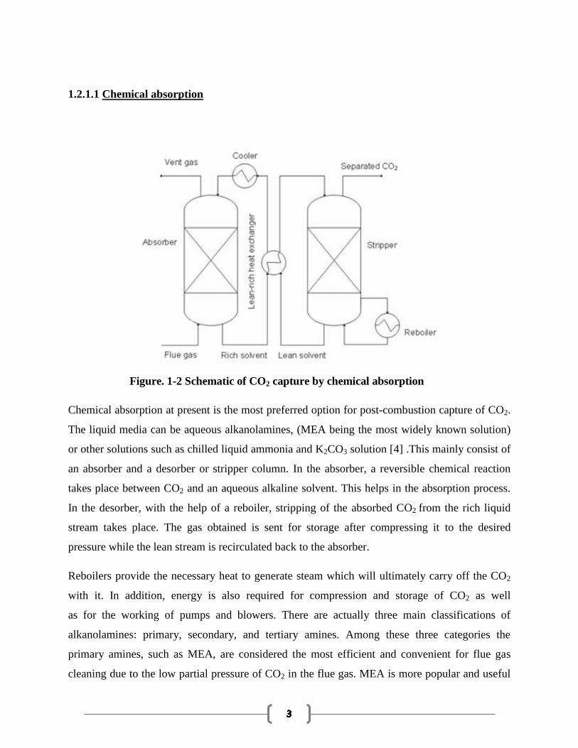
1.2.1.1 Chemical absorption
Figure. 1-2 Schematic of CO2 capture by chemical absorption
Chemical absorption at present is the most preferred option for post-combustion capture of CO2.
The liquid media can be aqueous alkanolamines, (MEA being the most widely known solution)
or other solutions such as chilled liquid ammonia and K2CO3 solution [4] .This mainly consist of
an absorber and a desorber or stripper column. In the absorber, a reversible chemical reaction
takes place between CO2 and an aqueous alkaline solvent. This helps in the absorption process.
In the desorber, with the help of a reboiler, stripping of the absorbed CO2 from the rich liquid
stream takes place. The gas obtained is sent for storage after compressing it to the desired
pressure while the lean stream is recirculated back to the absorber.
Reboilers provide the necessary heat to generate steam which will ultimately carry off the CO2
with it. In addition, energy is also required for compression and storage of CO2 as well
as for the working of pumps and blowers. There are actually three main classifications of
alkanolamines: primary, secondary, and tertiary amines. Among these three categories the
primary amines, such as MEA, are considered the most efficient and convenient for flue gas
cleaning due to the low partial pressure of CO2 in the flue gas. MEA is more popular and useful
solvent at low partial pressures of CO2 because it reacts at a rapid rate and the cost of the raw
material is low compared to other similar amines.
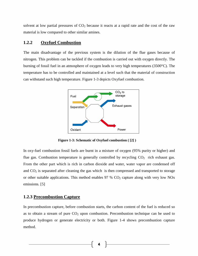
1.2.2 Oxyfuel Combustion
The main disadvantage of the previous system is the dilution of the flue gases because of
nitrogen. This problem can be tackled if the combustion is carried out with oxygen directly. The
burning of fossil fuel in an atmosphere of oxygen leads to very high temperatures (3500°C). The
temperature has to be controlled and maintained at a level such that the material of construction
can withstand such high temperature. Figure 1-3 depicts Oxyfuel combustion.
Figure 1-3: Schematic of Oxyfuel combustion ( [2] )
In oxy-fuel combustion fossil fuels are burnt in a mixture of oxygen (95% purity or higher) and
flue gas. Combustion temperature is generally controlled by recycling CO2 rich exhaust gas.
From the other part which is rich in carbon dioxide and water, water vapor are condensed off
and CO2 is separated after cleaning the gas which is then compressed and transported to storage
or other suitable applications. This method enables 97 % CO2 capture along with very low NOx
emissions. [5]
1.2.3 Precombustion Capture
In precombustion capture, before combustion starts, the carbon content of the fuel is reduced so
as to obtain a stream of pure CO2 upon combustion. Precombustion technique can be used to
produce hydrogen or generate electricity or both. Figure 1-4 shows precombustion capture
method.
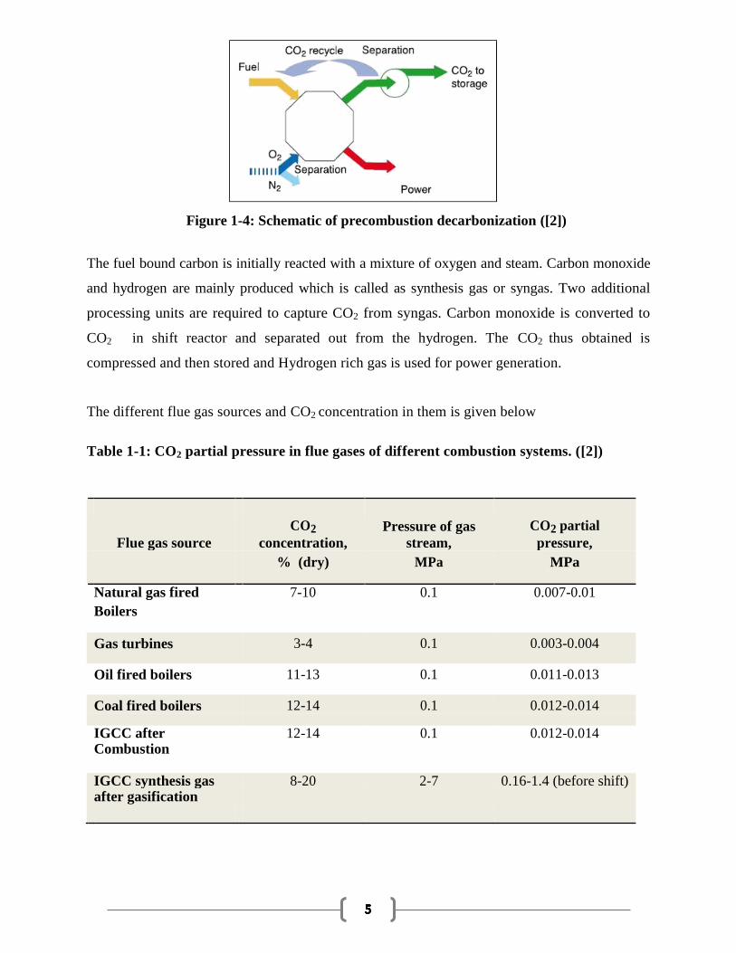
Figure 1-4: Schematic of precombustion decarbonization ([2])
The fuel bound carbon is initially reacted with a mixture of oxygen and steam. Carbon monoxide
and hydrogen are mainly produced which is called as synthesis gas or syngas. Two additional
processing units are required to capture CO2 from syngas. Carbon monoxide is converted to
CO2 in shift reactor and separated out from the hydrogen. The CO2 thus obtained is
compressed and then stored and Hydrogen rich gas is used for power generation.
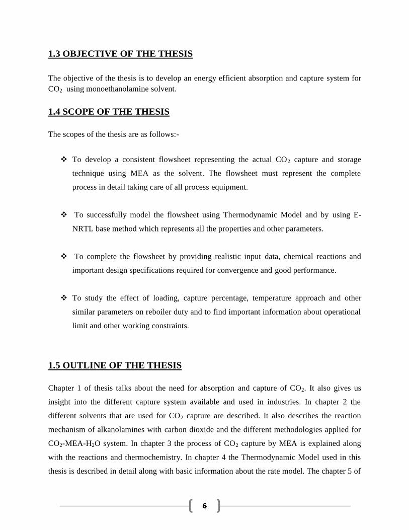
The different flue gas sources and CO2 concentration in them is given below
Table 1-1: CO2 partial pressure in flue gases of different combustion systems. ([2])
Flue gas source
CO2 Pressure of gas CO2 partial
concentration, stream, pressure,
% (dry) MPa MPa
Natural gas fired 7-10 0.1 0.007-0.01
Boilers
Gas turbines 3-4 0.1 0.003-0.004
Oil fired boilers 11-13 0.1 0.011-0.013
Coal fired boilers 12-14 0.1 0.012-0.014
IGCC after 12-14 0.1 0.012-0.014
Combustion
IGCC synthesis gas 8-20 2-7 0.16-1.4 (before shift)
after gasification
1.3 OBJECTIVE OF THE THESIS
The objective of the thesis is to develop an energy efficient absorption and capture system for
CO2 using monoethanolamine solvent.
1.4 SCOPE OF THE THESIS
The scopes of the thesis are as follows:-
To develop a consistent flowsheet representing the actual CO2 capture and storage
technique using MEA as the solvent. The flowsheet must represent the complete
process in detail taking care of all process equipment.
To successfully model the flowsheet using Thermodynamic Model and by using E-
NRTL base method which represents all the properties and other parameters.
To complete the flowsheet by providing realistic input data, chemical reactions and
important design specifications required for convergence and good performance.
To study the effect of loading, capture percentage, temperature approach and other
similar parameters on reboiler duty and to find important information about operational
limit and other working constraints.
1.5 OUTLINE OF THE THESIS
Chapter 1 of thesis talks about the need for absorption and capture of CO2. It also gives us
insight into the different capture system available and used in industries. In chapter 2 the
different solvents that are used for CO2 capture are described. It also describes the reaction
mechanism of alkanolamines with carbon dioxide and the different methodologies applied for
CO2-MEA-H2O system. In chapter 3 the process of CO2 capture by MEA is explained along
with the reactions and thermochemistry. In chapter 4 the Thermodynamic Model used in this
thesis is described in detail along with basic information about the rate model. The chapter 5 of
this work is about the simulation of the process using thermodynamic model. Here different
input and design specifications are mentioned. Chapter – 6 deals with the results obtained from
the simulation and give an inference about the results. The Chapter-7 represents the conclusion
and the future work that can be carried out later.
CHAPTER-2
LITERATURE REVIEW
2.1 SOLVENTS USED FOR CO2 CAPTURE
CO2 capture is basically done by absorption with aqueous alkanolamines. These amines are bases
which react with acid species. The alcohol groups enable them to be soluble in water. The first
alkanolamines to be used industrially was Monoethanolamine (MEA). They may categorized into
primary , secondary , tertiary types according to the number of organic groups that are attached
to the alkaline nitrogen .These varieties of amines have different reaction mechanism , reaction
products and the heat of reaction. Primary and secondary amines usually react faster than tertiary
amines with higher heat of absorption in these amines. While the advantage of fast reacting amine
solvent is a smaller absorber, the main difficulty is the energy required to regenerate the solvent.
As a result a proper solvent must be selected. Several works are being carried out to develop
mixed solvents so as to make this procedure more effective. Bishnoi (2000) [6] and Dang
(2001)[7] have been working in this regard by working on Piperzine promoted MDEA and MEA
respectively. Cullinane (2002) also studied the use and properties of Piperzine promoted
potassium carbonate. But still more work is required and thus these mixed solvents are not yet
used in industry. [8]
2.2 ALKANOLAMINE AND ITS REACTION WITH CO2
In CO2 absorption, carbamate formation is a very important step.. Two mechanisms have been
proposed for the formation of the carbamate – the zwitterion mechanism and the termolecular
mechanism
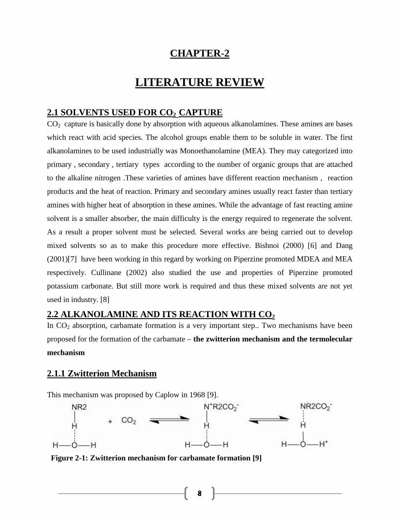
2.1.1 Zwitterion Mechanism
This mechanism was proposed by Caplow in 1968 [9].
Figure 2-1: Zwitterion mechanism for carbamate formation [9]

According to Caplow hydrogen bond is formed between the amine and the water molecules
before any reaction with CO2 takes place. Initially an unstable intermediate was formed due the
bonding between the amine and the carbon dioxide molecules. Next a carbamate is formed by the
transfer of the amine proton. The base used basically is either water molecule or an amine. The
kinetic expressions for this , was given by Kumar et al. in 2003. In lean aqueous solutions, the
deprotonation of the zwitterion is caused by OH- to form the carbamate species.
2.1.2 Termolecular Mechanism A termolecular single-step mechanism for carbamate formation was proposed in 1989 [10]] and
is shown in Figure2.2.
Figure 2-2- Termolecular mechanism for carbamate formation [10]
In this mechanism, the bond formation between alkanolamines and CO2 and the proton transfer
take place simultaneously. This mechanism described here is actually not very different from the
one given by Caplow. Caplow’s mechanism approaches the termolecular mechanism when the
lifetime of the Zwitterion is very small. Both these mechanism can be fitted to experimental data
as they allow and work for different amine concentration. An equally effective representation of
reaction rates should be possible using either mechanism.
2.3 MODELING OF CO2 -MEA-WATER SYSTEM
Over the years large experimental data have been collected on CO2-MEA-H2O system. These
data have been used to study thermodynamic equilibrium, rates of absorption and rates of
reaction. To reproduce and validate these data many thermodynamic models and rate models have
been created. Among the thermodynamic models, the Kent and Eisenberg Method (1976) were
initially best known for its simplicity. Gradually other models were developed and currently the
most used model is the Electrolyte-NRTL model, developed by Chen et al. (1979). It is a model

based on excess Gibbs’s energy of a mixture and was successfully used over a wide range of
temperature and loadings. Rigorous thermodynamic models generally are based on experimental
data collected by Joe et al (1995)[11] whereas as Rate models are developed using absorption rate
collected by Dang (2001) . This type of modelling is generally done by the help of ASPEN PLUS
software. In the past, other models have also been completed using either commercial software or
language codes. TSWEET, an amine gas sweetening computer program, have been used since
early eighties for modelling of Acid Gas removal and the results are found in the literature
(Holmes et al. 1984).[12] Another software that is used is AMSIM, which uses a rigorous non –
equilibrium stage model (Zhang et al. 1996)[13]. Also different programs have also been written
in FORTRAN or Visual Basic and are specific for amine gas treating. All these different
integrated models though provide better insight on the overall phenomena but are usually slower
and cause great difficulty in simulating the whole process. ASPEN PLUS on the other hand
provides tools to perform analysis of the whole process and understanding the effect of design
variable on each other.
CHAPTER-3
MONOETHANOLAMINE SYSTEM
Monoethanolamine (MEA) is widely used for the removal of CO2 from flue gas and has been
described in detail in many sources. For non-selective removal of acid gas, MEA has been
extensively used as a solvent for the past 60 years. Presently, attempts are being made by Fluor
to commercialize CO2 capture technologies based on MEA [14]. The Fluor process uses a 30 wt.
% MEA solvent. In order to prevent equipment corrosion and solvent degradation the solvent is
mixed with inhibitors. In general, if CO2 is the only acidic gas being absorbed then one can use
amine concentration of up to 35 wt. % along with a corrosion inhibitor [15].
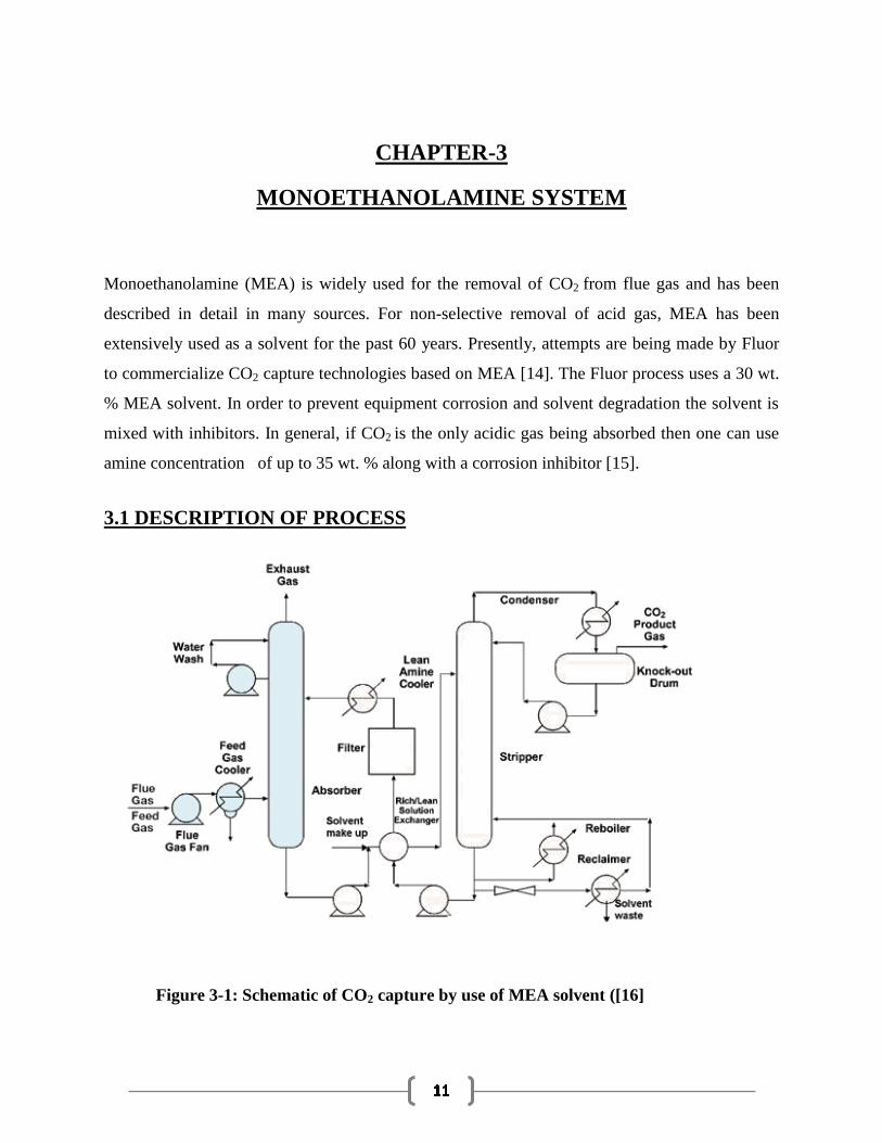
3.1 DESCRIPTION OF PROCESS
Figure 3-1: Schematic of CO2 capture by use of MEA solvent ([16]
CO2 capture using MEA is a combination of absorption and desorption and the whole process
can be divided into:-
1. Flue gas cooling and compression
2. Absorption of CO2 and regeneration of solvent
3. CO2 compression
A schematic of the process is shown in Figure 3-1 [16]. Each of these steps is discussed in detail
below.
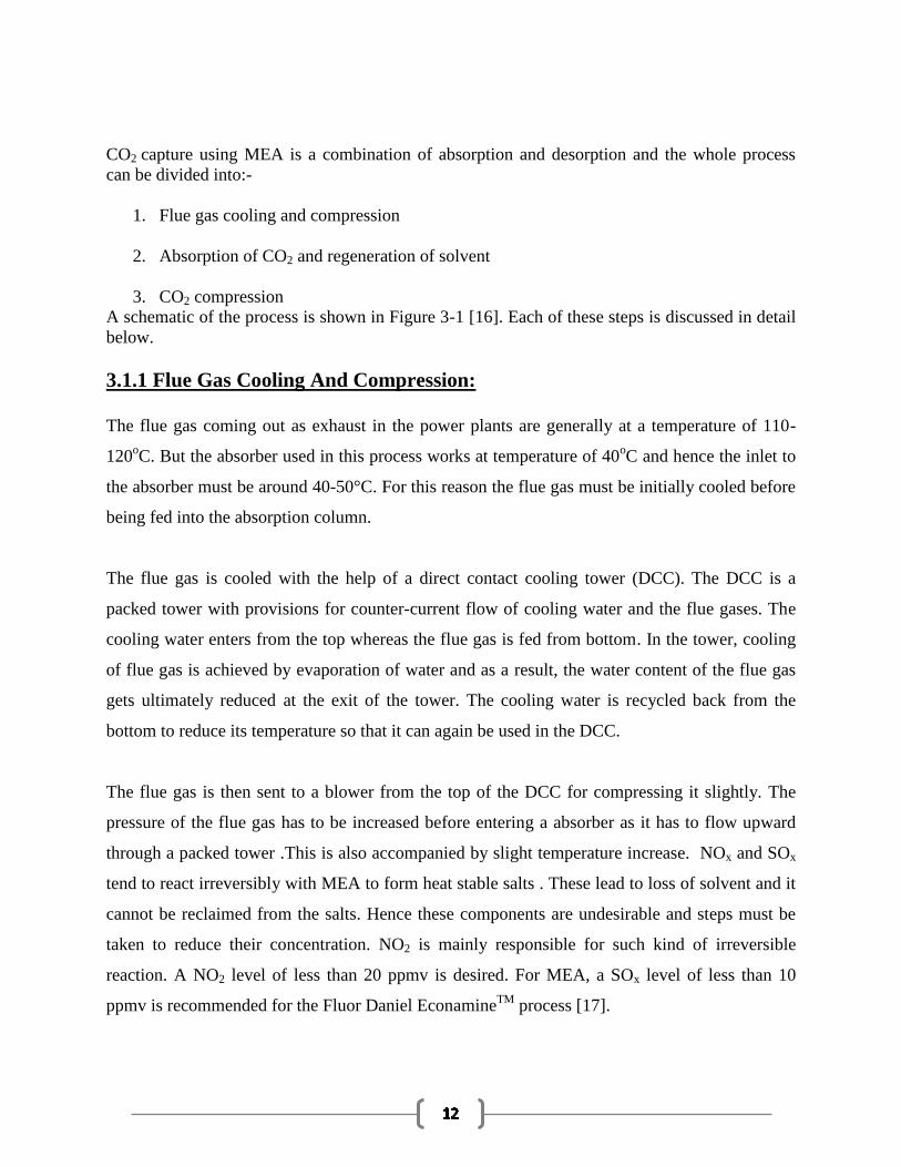
3.1.1 Flue Gas Cooling And Compression:
The flue gas coming out as exhaust in the power plants are generally at a temperature of 110-
120oC. But the absorber used in this process works at temperature of 40
oC and hence the inlet to
the absorber must be around 40-50°C. For this reason the flue gas must be initially cooled before
being fed into the absorption column.
The flue gas is cooled with the help of a direct contact cooling tower (DCC). The DCC is a
packed tower with provisions for counter-current flow of cooling water and the flue gases. The
cooling water enters from the top whereas the flue gas is fed from bottom. In the tower, cooling
of flue gas is achieved by evaporation of water and as a result, the water content of the flue gas
gets ultimately reduced at the exit of the tower. The cooling water is recycled back from the
bottom to reduce its temperature so that it can again be used in the DCC.
The flue gas is then sent to a blower from the top of the DCC for compressing it slightly. The
pressure of the flue gas has to be increased before entering a absorber as it has to flow upward
through a packed tower .This is also accompanied by slight temperature increase. NOx and SOx
tend to react irreversibly with MEA to form heat stable salts . These lead to loss of solvent and it
cannot be reclaimed from the salts. Hence these components are undesirable and steps must be
taken to reduce their concentration. NO2 is mainly responsible for such kind of irreversible
reaction. A NO2 level of less than 20 ppmv is desired. For MEA, a SOx level of less than 10
ppmv is recommended for the Fluor Daniel EconamineTM
process [17].
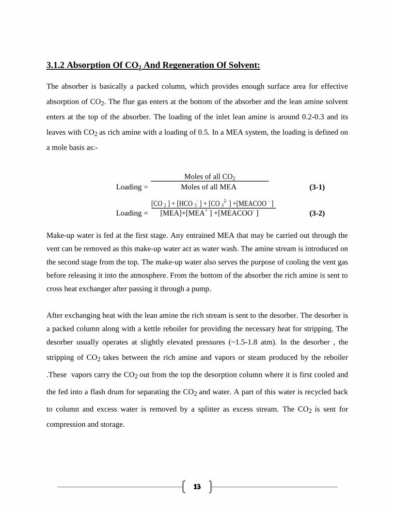
3.1.2 Absorption Of CO2 And Regeneration Of Solvent:
The absorber is basically a packed column, which provides enough surface area for effective
absorption of CO2. The flue gas enters at the bottom of the absorber and the lean amine solvent
enters at the top of the absorber. The loading of the inlet lean amine is around 0.2-0.3 and its
leaves with CO2 as rich amine with a loading of 0.5. In a MEA system, the loading is defined on
a mole basis as:-
Loading =
Moles of all CO2
(3-1)
Moles of all MEA
Loading =
[CO 2 ] + [HCO 3- ] + [CO 3
2- ] +[MEACOO
- ]
(3-2)
[MEA]+[MEA+ ] +[MEACOO
- ]
Make-up water is fed at the first stage. Any entrained MEA that may be carried out through the
vent can be removed as this make-up water act as water wash. The amine stream is introduced on
the second stage from the top. The make-up water also serves the purpose of cooling the vent gas
before releasing it into the atmosphere. From the bottom of the absorber the rich amine is sent to
cross heat exchanger after passing it through a pump.
After exchanging heat with the lean amine the rich stream is sent to the desorber. The desorber is
a packed column along with a kettle reboiler for providing the necessary heat for stripping. The
desorber usually operates at slightly elevated pressures (~1.5-1.8 atm). In the desorber , the
stripping of CO2 takes between the rich amine and vapors or steam produced by the reboiler
.These vapors carry the CO2 out from the top the desorption column where it is first cooled and
the fed into a flash drum for separating the CO2 and water. A part of this water is recycled back
to column and excess water is removed by a splitter as excess stream. The CO2 is sent for
compression and storage.

3.1.3 CO2 Compression:
The CO2 gas obtained from the flash drum needs to be dried and compressed before it is fit for
storage. During the transport of CO2 gas any kind moisture presence can lead to corrosion of
pipelines and equipment. As a result drying becomes very important. Drying and compression,
both can achieve by the use of a 4-stage reciprocating compressor with provision of cooling
between the stages. This not only helps in separating out the water present but also compresses
the CO2 to 90 atm. The CO2 is further compressed to 130 atm with the help of pumps so that
these can be easily stored and transported as supercritical liquid.
3.2 CHEMISTRY OF THE MEA SYSTEM
In the MEA system, CO2 is solubilized in the liquid phase either in a carbamate, carbonate or
bicarbonate form. The following reversible reactions occur in the MEA system:
2 H2 O ↔ H3O+ + OH
- (3-3)
CO2 + 2 H2 O ↔ HCO3- + H3O
+ (3-4)
MEA + HCO3- ↔ MEACOO
- + H2O (3-5)
MEA + H3 O+ ↔ MEA
+ + H2O (3-6)
HCO3- + H2 O ↔ CO3
2 − + H3O
+ (3-7)
The equilibrium constants for the reaction are temperature dependent and follow the dependence
given in (3-8).
ln K x = A + B
+ C ln T + DT (3-8)
T
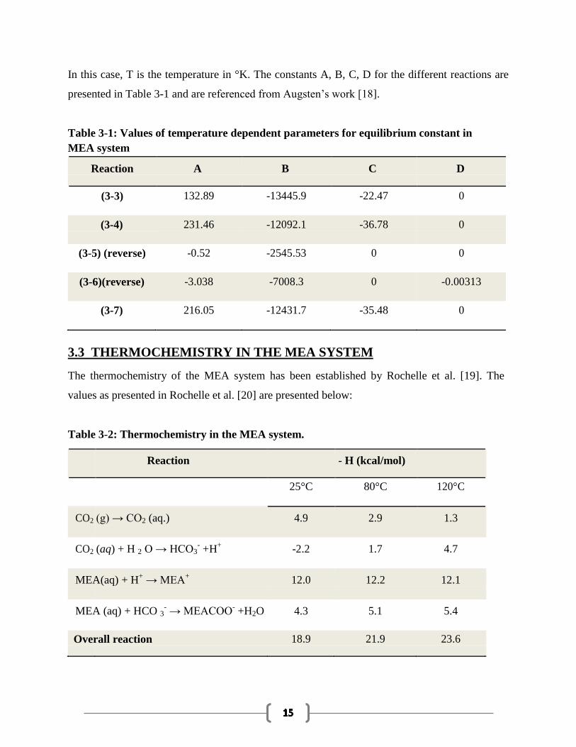
In this case, T is the temperature in °K. The constants A, B, C, D for the different reactions are
presented in Table 3-1 and are referenced from Augsten’s work [18].
Table 3-1: Values of temperature dependent parameters for equilibrium constant in
MEA system
Reaction A B C D
(3-3) 132.89 -13445.9 -22.47 0
(3-4) 231.46 -12092.1 -36.78 0
(3-5) (reverse) -0.52 -2545.53 0 0
(3-6)(reverse) -3.038 -7008.3 0 -0.00313
(3-7) 216.05 -12431.7 -35.48 0
3.3 THERMOCHEMISTRY IN THE MEA SYSTEM The thermochemistry of the MEA system has been established by Rochelle et al. [19]. The
values as presented in Rochelle et al. [20] are presented below:
Table 3-2: Thermochemistry in the MEA system.
Reaction - H (kcal/mol)
25°C 80°C 120°C
CO2 (g) → CO2 (aq.) 4.9 2.9 1.3
CO2 (aq) + H 2 O → HCO3- +H
+ -2.2 1.7 4.7
MEA(aq) + H+ → MEA
+ 12.0 12.2 12.1
MEA (aq) + HCO 3- → MEACOO
- +H2O 4.3 5.1 5.4
Overall reaction 18.9 21.9 23.6
CHAPTER-4
THERMODYNAMIC AND RATE MODEL
There are actually 2 types of modelling which are used for simulation and analysis of CO2-
MEA-H2O system. These are
Thermodynamic Modeling
Rate Based Modeling
4.1 THERMODYNAMIC MODEL
Thermodynamic model assumes the overall process to be at equilibrium although CO2
absorption is a non-equilibrium process. The vapor and the liquid are assumed to be at
equilibrium at each stage of the column. In this model the absorption/stripping process require
rigorous thermodynamics. To determine the amount of conversion that can take place or for
convergence of the simulation we need to have knowledge about their equilibrium
compositions. When MEA is used for CO2 absorption process, it is observed that ions and polar
molecules are formed and as a result of which Electrolyte-NRTL framework is generally used
to describe the thermodynamic model..
4.1.1 Electrolyte NRTL Model
Chen and Evans (1979) originally developed the model which was later extended by Mock Et .al
for various other mixed solvents. The Electrolyte – NRTL model is based on the excess Gibbs
free energy of a solution. This model considers the presence of polar ions and states that the
excess Gibbs free energy in the electrolyte system is the sum of two contributions [20-21]:
1. Short-range forces between all the species that includes the local ion-molecule, ion-
ion, and molecule-molecule interactions.
2. Long-range electrostatic ion-ion interactions.
Thus, the expression for the excess Gibbs free energy as calculated by the Electrolyte NRTL
model can be expressed as:
Gex*
= Gex*, LR
+ Gex*, local
(4.1)
GE
is the excess Gibbs free energy, defined as
GE=G-G
id (4.2)
Where Gid
is the excess Gibbs free energy if the mixture were ideal. The excess Gibbs free
energy is related to excess enthalpy and excess entropy of mixing by
GE=H
E-TS
E (4.3)
In process involving MEA, ions are present in large numbers which tend to interact which each
other strongly. The CO2 molecules present tend to reduce these interactions. Moreover as the
composition changes the interactions between the different component also changes and the
excess enthalpy is determined from it. It is also observed because of these reasons the CO2 tend
to leave the liquid phase when the solution has high ionic strength, because this results in
reducing the overall enthalpy. With the help of the theory of Debye-Huckel which was later
modified by Pitzer the long term ionic forces can be described. The ionic strength of solution
affects these forces to a great extent. .The molecular forces which are basically short range
forces, need to be included in the model to include the effect of hydrogen bonds and local
interactions of molecules with molecules, molecules with ion pairs and ion with ion pairs. Thus
the E-NRTL model is mainly based on 2 assumptions
Like-ion repulsion assumption: It is assumed the local composition of cations and
anions around themselves is zero due to the large repulsive forces present between the
same ionic charged particles..
Local electro neutrality assumption: It is also assumed that the distribution of the
cations and anions around a central solvent molecule is there in such a manner that
ensures the net local ionic charge to be zero.
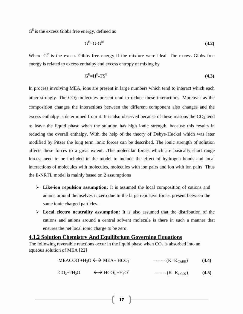
4.1.2 Solution Chemistry And Equilibrium Governing Equations
The following reversible reactions occur in the liquid phase when CO2 is absorbed into an
aqueous solution of MEA [22]
MEACOO-+H2O MEA+ HCO3
- ------- (K=KCARB) (4.4)
CO2+2H2O HCO3-+H3O
+ ------- (K=Ka,CO2) (4.5)

HCO3-+H2O CO3
-+H3O
+ ------- (K=KA, HCO3
-) (4.6)
MEAH+ + H2O MEA+H3O
+ ------- (K=KA, MEAH
+) (4.7)
2H2O H3O+ + OH
- ------- (K=KW) (4.8)
For every reaction there exists an equilibrium constraint. We need to find the mole fraction of
each component in both the phases to ultimately solve the thermodynamic problem for a CO2-
MEA-H2O system. These data are to be found at a particular temperature and pressure. Since the
ions present are non-volatile, only H2O, MEA, CO2 are in vapor phase. So we face a situation
where there are 9 components, and 12 unknowns with 12 equations. The MEA concentration and
loading of CO2 in the solution are the known variables in the problem. The solving equations are
the equations for the five equilibrium constraints(equation-4.9), the CO2 material
balance(equation 4.10), the MEA balance(equation 4.11), the total material balance(equation
4.12), electro neutrality(equation 4.13) and the phase relationships for CO2,MEA and water
balance(equation 4.14-4.16) [22]
Kj = πi(ai)reactant/ πi(ai)product (4.9)
XCO2 total = XCO2 +XHCO3- +XCO3
- +XMEACOO
- (4.10)
XMEA tot = XMEA+ XMEAH+
+ XMEACOO- (4.11)
1 = xCO2+xMEA +xH20 +xHCO3- +xCO3
- +xMEACOO
- +xMEAH
- + xH3O
+ + xOH
- (4.12)
0 = (xHCO3- + xMEACOO
- + xOH
- +2xCO3
-) - (xMEAH
+ + xH3O
+) (4.13)
PyCO2 = ¥CO2*HCO2XCO2 (4.14)
PyH2O = ¥H2OPH2OXH2O (4.15)
PYMEA = ¥MEAPMEA*XMEA (4.16)
Ai=activity of component i in solution and ¥ is the stoichiometric coefficient of component i in
reaction j.
HCO2=Henry’s constant of CO2 in the solvent
PH2O* and PMEA
*=vapor pressure of H2O and MEA respectively
But there are some errors or disadvantages of this method. Since the loading changes the MEA
concentration as well as the ions present, the reference state assumed initially also should vary.
But as the Gibbs free energy of formation is assumed to be fixed these changes cannot be
incorporated in the model. This ultimately results in a thermodynamic bug or problem in the
ASPEN PLUS.
4.2 RATE MODEL
The absorption of carbon dioxide in monoethanolamine is actually a non-equilibrium process.
The CO2 reacts with MEA at a finite rate and according to specific kinetics. The reaction take
place at fast rate but they are not close to equilibrium at the operating conditions. Hence, in these
cases, a more robust Rate- Based Model is used.
The RATEFRAC mode in Aspen Plus is used for the rate based simulation of the desorber and
the absorber. [23]. It is a stage based model and incorporates mass and heat transfer phenomena
as well as the kinetics of chemical reactions. The various equations that are solved in ASPEN
RateSep include [23]:
Mass and heat balances for the vapor and liquid phases
Mass and heat transfer rate models to determine interphase transfer rates
Vapor-liquid equilibrium equations for the interphase
Estimation of mass and heat transfer coefficients and interfacial areas
Enhancement of mass and heat transfer processes by chemical reactions
The two-film theory is used to explain the process and uses film discretization technique for
accurate concentration profile. It also combines the film equations with separate balance
equations for the liquid and vapor phase, diffusion and reaction kinetics, electrolyte solution
chemistry and thermodynamics [24].
In this work we are focusing only on Thermodynamic modelling. Using the results of
thermodynamic modeling one is able to get the desired results and further synthesis the process
using the Rate based Model.

CHAPTER-5
SIMULATION ACCORDING TO THERMODYNAMIC MODEL
Figure 5-1: Flowsheet of MEA system as developed in ASPEN Plus [25]
The thermodynamic model was applied and thus the absorber and desorber were developed as a
set of stages each at equilibrium conditions. The flow sheet was modeled as an open loop system
to facilitate easier convergence. This also helped to carry out multiple simulations quickly. But
for the open loop system to converge we need some robust design specifications which take care
of parameters important for the convergence of the process. The different reactions provided
were also assumed to be at equilibrium and data for their equilibrium constant was fed.
The above flowsheet was developed in ASPEN PLUS software. The absorber, desorber and direct
contact cooling tower (DCC) were selected and modeled as RADFRAC columns with desorber
having a kettle reboiler. [25] The flash is a high pressure separator which separates the CO2 and
water. A dot splitter was used to remove the excess water and a fraction was recycled back to the
desorber. The CO2 so obtained was sent to the 4 stage reciprocating compressor with cooling in
between stages. In each stage a gradual compression takes place and finally CO2 was obtained at
90 atm pressure. The compressor was a MCOMP model and water was decanted out in each
stage. A set of pumps and heaters were selected and used for varying pressure and temperature to
the required value.
5.1 STEPS INVOLVED IN DEVELOPING THE FLOWSHEET
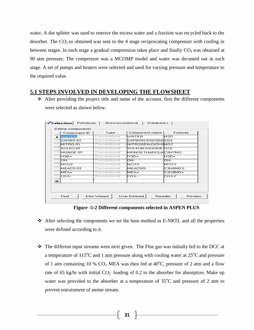
After providing the project title and name of the account, first the different components
were selected as shown below.
Figure -5-2 Different components selected in ASPEN PLUS
After selecting the components we set the base method as E-NRTL and all the properties
were defined according to it.
The different input streams were next given. The Flue gas was initially fed to the DCC at
a temperature of 115oC and 1 atm pressure along with cooling water at 25
oC and pressure
of 1 atm containing 10 % CO2. MEA was then fed at 40oC, pressure of 2 atm and a flow
rate of 65 kg/hr with initial CO2 loading of 0.2 to the absorber for absorption. Make up
water was provided to the absorber at a temperature of 35oC and pressure of 2 atm to
prevent entrainment of amine stream.
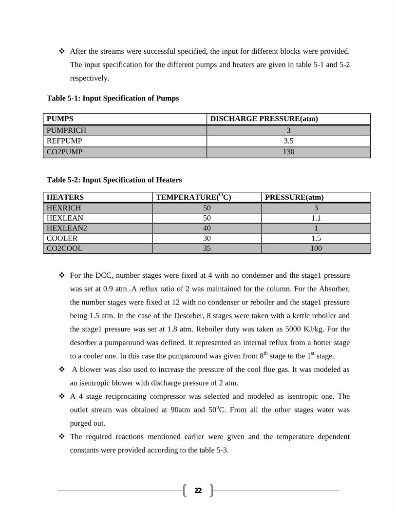
After the streams were successful specified, the input for different blocks were provided.
The input specification for the different pumps and heaters are given in table 5-1 and 5-2
respectively.
Table 5-1: Input Specification of Pumps
PUMPS DISCHARGE PRESSURE(atm)
PUMPRICH 3
REFPUMP 3.5
CO2PUMP 130
Table 5-2: Input Specification of Heaters
HEATERS TEMPERATURE(O
C) PRESSURE(atm)
HEXRICH 50 3
HEXLEAN 50 1.1
HEXLEAN2 40 1
COOLER 30 1.5
CO2COOL 35 100
For the DCC, number stages were fixed at 4 with no condenser and the stage1 pressure
was set at 0.9 atm .A reflux ratio of 2 was maintained for the column. For the Absorber,
the number stages were fixed at 12 with no condenser or reboiler and the stage1 pressure
being 1.5 atm. In the case of the Desorber, 8 stages were taken with a kettle reboiler and
the stage1 pressure was set at 1.8 atm. Reboiler duty was taken as 5000 KJ/kg. For the
desorber a pumparound was defined. It represented an internal reflux from a hotter stage
to a cooler one. In this case the pumparound was given from 8th
stage to the 1st stage.
A blower was also used to increase the pressure of the cool flue gas. It was modeled as
an isentropic blower with discharge pressure of 2 atm.
A 4 stage reciprocating compressor was selected and modeled as isentropic one. The
outlet stream was obtained at 90atm and 50oC. From all the other stages water was
purged out.
The required reactions mentioned earlier were given and the temperature dependent
constants were provided according to the table 5-3.
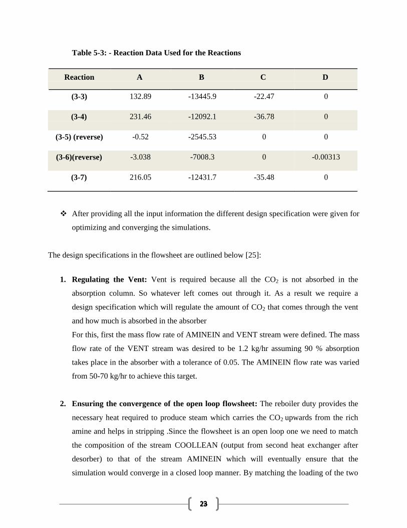
Table 5-3: - Reaction Data Used for the Reactions
Reaction A B C D
(3-3) 132.89 -13445.9 -22.47 0
(3-4) 231.46 -12092.1 -36.78 0
(3-5) (reverse) -0.52 -2545.53 0 0
(3-6)(reverse) -3.038 -7008.3 0 -0.00313
(3-7) 216.05 -12431.7 -35.48 0
After providing all the input information the different design specification were given for
optimizing and converging the simulations.
The design specifications in the flowsheet are outlined below [25]:
1. Regulating the Vent: Vent is required because all the CO2 is not absorbed in the
absorption column. So whatever left comes out through it. As a result we require a
design specification which will regulate the amount of CO2 that comes through the vent
and how much is absorbed in the absorber
For this, first the mass flow rate of AMINEIN and VENT stream were defined. The mass
flow rate of the VENT stream was desired to be 1.2 kg/hr assuming 90 % absorption
takes place in the absorber with a tolerance of 0.05. The AMINEIN flow rate was varied
from 50-70 kg/hr to achieve this target.
2. Ensuring the convergence of the open loop flowsheet: The reboiler duty provides the
necessary heat required to produce steam which carries the CO2 upwards from the rich
amine and helps in stripping .Since the flowsheet is an open loop one we need to match
the composition of the stream COOLLEAN (output from second heat exchanger after
desorber) to that of the stream AMINEIN which will eventually ensure that the
simulation would converge in a closed loop manner. By matching the loading of the two
streams this condition is met. We need to first develop 2 prop sets in the property module
PS-1 and PS-2 and then define FAPPCO2 and FAPPMEA in Prop sets tab which actually
calculate the apparent molar flows of CO2 and MEA in the stream. The ratio of
FAPPCO2 to FAPPMEA gives us the loading of the stream. This loading must be equal
the initial loading of the AMINEIN stream so that it can be understood and accepted that
the COOLLEAN stream can be recycled back to the absorber and the system will
converge. This is achieved by varying the reboiler duty of the desorber.
After the prop sets have been defined, design specification of the desorber was specified.
This design specification checks the property ratio or the ratio of the two prop sets of the
LEAN stream coming out of the desorber. The reboiler duty was varied from 5000 to
15000 watt to reach the desired loading of 0.2 as of the AMINEIN stream.
3. Satisfy the conditions for Cross Heat Exchanger: In this flowsheet, the two separate
heat exchangers – HEXRICH and HEXLEAN function as a cross heat exchanger to
ensure that a closed loop is not formed. As a result the heat duties of the two heat
exchangers will be equal but of the opposite sign. To ensure this a design specification
was provided in the Flowsheeting options tab which regulates the heat duties of the
exchangers..
Initially the heat duties of the two heat exchangers were defined. Since we have assumed
that the heat duties of HEXRICH and HEXLEAN are equal but of opposite sign it was
specified that the sum of the heat duties is desired to be 0 with a tolerance of 0.02. The
mass flow rate of AMINEIN stream was varied from 50-70 kg/hr to satisfy the desired
condition.
4. Maintaining a approach temperature: The temperature approach of the cross heat
exchangers is also an important pre-requisite for the optimum performance of the
process. For this a design specification was defined that regulated the temperature
approach by ensuring that the temperature of the outlet stream of HEXLEAN is 10°C
above the temperature of the inlet stream to HEXRICH.
For this purpose first the temperature of LEANCOOL and RICHPUMP were defined. It
was specified that the temperature of LEANCOOL to be 10oC more than the temperature
of RICHPUMP with a tolerance of 0.1. To achieve this we need to vary the AMINEIN
mass flow rate from 50-70 kg/hr.
5. Water balance: Water balance in the plant has to be maintained in order to have
closed loop convergence. For this purpose, the flow rate of the makeup water stream is
varied to achieve an overall water balance.
To ensure water balance we first need to define the mass flow rate of CW, CW1,
and MAKEUP WATER, 1, 2 and 3 streams. It was specified that sum of the expression
(CW+MAKEUP WATER-CW1-1-2-3) should be equal to zero with a tolerance of 0.02.
To attain water balance we need to vary the MAKEUP WATER from 40-60 kg/hr.
CHAPTER-6
RESULTS AND DISCUSSION
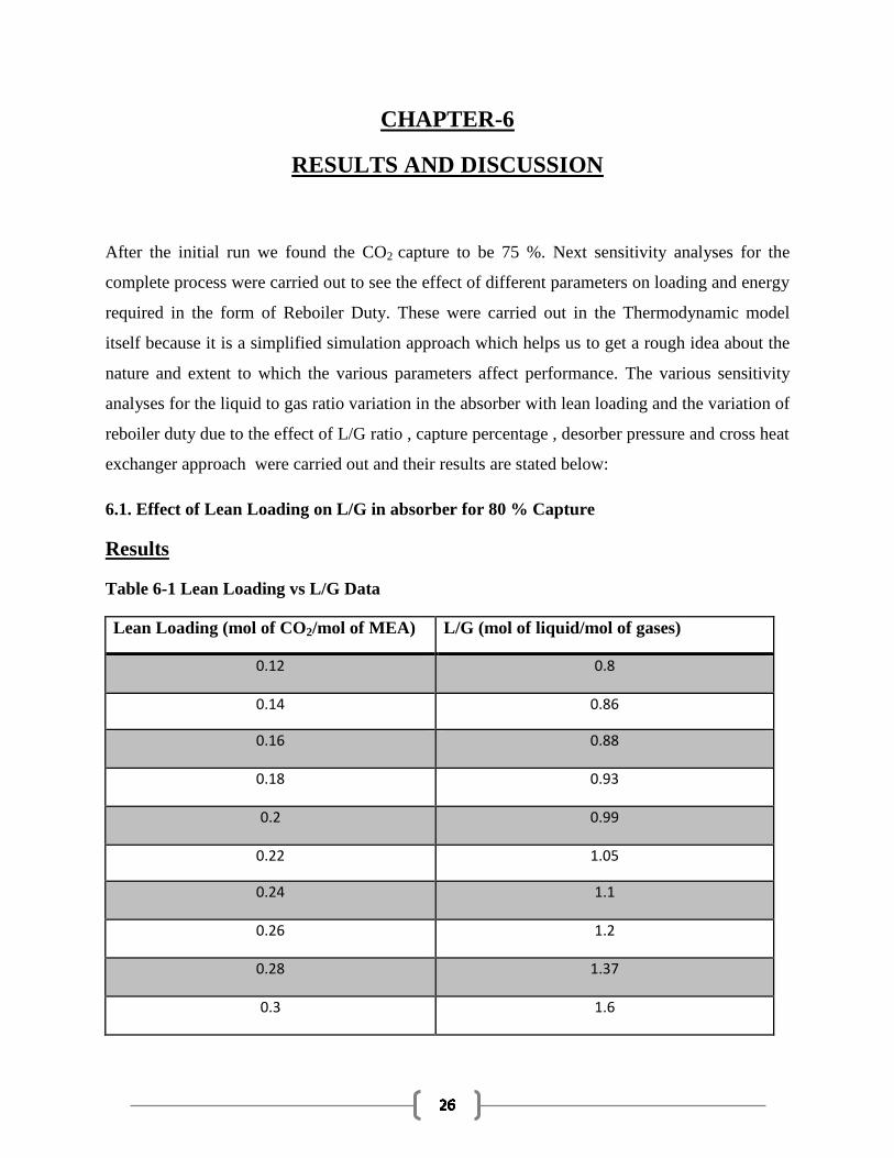
After the initial run we found the CO2 capture to be 75 %. Next sensitivity analyses for the
complete process were carried out to see the effect of different parameters on loading and energy
required in the form of Reboiler Duty. These were carried out in the Thermodynamic model
itself because it is a simplified simulation approach which helps us to get a rough idea about the
nature and extent to which the various parameters affect performance. The various sensitivity
analyses for the liquid to gas ratio variation in the absorber with lean loading and the variation of
reboiler duty due to the effect of L/G ratio , capture percentage , desorber pressure and cross heat
exchanger approach were carried out and their results are stated below:
6.1. Effect of Lean Loading on L/G in absorber for 80 % Capture
Results
Table 6-1 Lean Loading vs L/G Data
Lean Loading (mol of CO2/mol of MEA) L/G (mol of liquid/mol of gases)
0.12 0.8
0.14 0.86
0.16 0.88
0.18 0.93
0.2 0.99
0.22 1.05
0.24 1.1
0.26 1.2
0.28 1.37
0.3 1.6
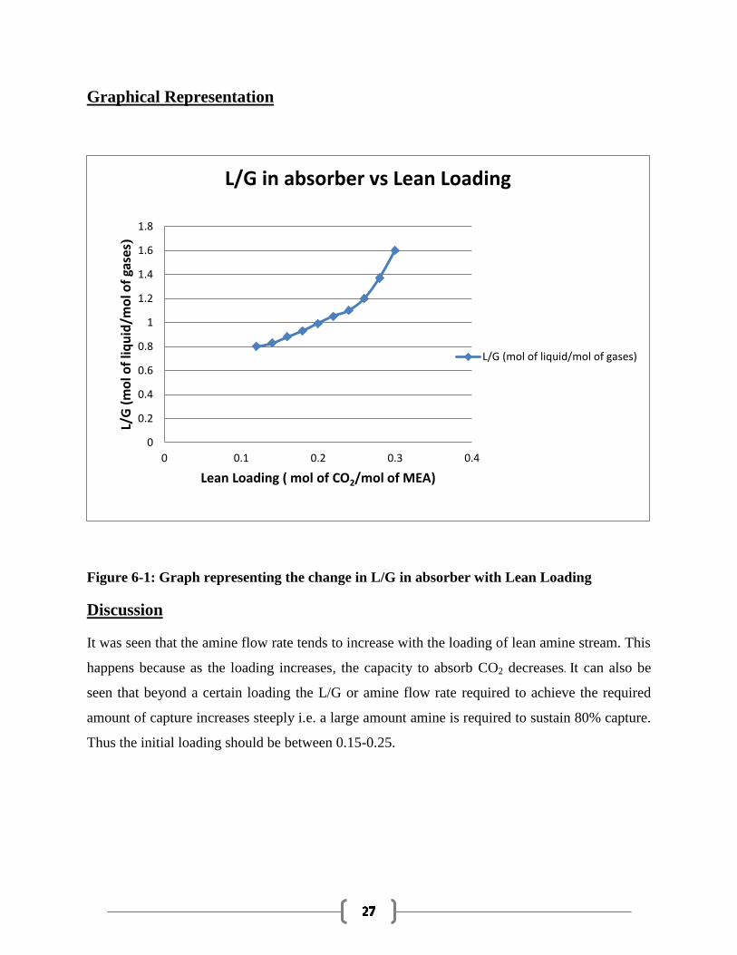
Graphical Representation
Figure 6-1: Graph representing the change in L/G in absorber with Lean Loading
Discussion
It was seen that the amine flow rate tends to increase with the loading of lean amine stream. This
happens because as the loading increases, the capacity to absorb CO2 decreases. It can also be
seen that beyond a certain loading the L/G or amine flow rate required to achieve the required
amount of capture increases steeply i.e. a large amount amine is required to sustain 80% capture.
Thus the initial loading should be between 0.15-0.25.
0
0.2
0.4
0.6
0.8
1
1.2
1.4
1.6
1.8
0 0.1 0.2 0.3 0.4
L/G
(m
ol o
f liq
uid
/mo
l of
gase
s)
Lean Loading ( mol of CO2/mol of MEA)
L/G in absorber vs Lean Loading
L/G (mol of liquid/mol of gases)
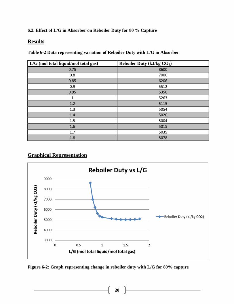
6.2. Effect of L/G in Absorber on Reboiler Duty for 80 % Capture
Results
Table 6-2 Data representing variation of Reboiler Duty with L/G in Absorber
L/G (mol total liquid/mol total gas) Reboiler Duty (kJ/kg CO2)
0.75 8600
0.8 7000
0.85 6206
0.9 5512
0.95 5350
1 5263
1.2 5115
1.3 5054
1.4 5020
1.5 5004
1.6 5015
1.7 5035
1.8 5078
Graphical Representation
Figure 6-2: Graph representing change in reboiler duty with L/G for 80% capture
3000
4000
5000
6000
7000
8000
9000
0 0.5 1 1.5 2
Reb
oile
r D
uty
(kJ
/kg
CO
2)
L/G (mol total liquid/mol total gas)
Reboiler Duty vs L/G
Reboiler Duty (kJ/kg CO2)
Discussion
It can be seen from the above figure that initially at very low loading of lean stream the reboiler
duty is very high, because at low loading, the equilibrium partial pressure of CO2 is very low. As
a result a large amount of steam is required to strip the solution to the required lean loading in
the desorber and thus a large amount of energy is lost in vaporization and condensation of water.
Gradually as the lean loading increases, partial pressure of CO2 in the amine stream increases as
a result of which the amount of steam that is required to facilitate the stripping decreases. So the
heat or energy required also decreases thus reducing the reboiler duty. But with increase in
loading beyond a limit it again starts increasing because the amount of amine required to achieve
80 % capture also increases.
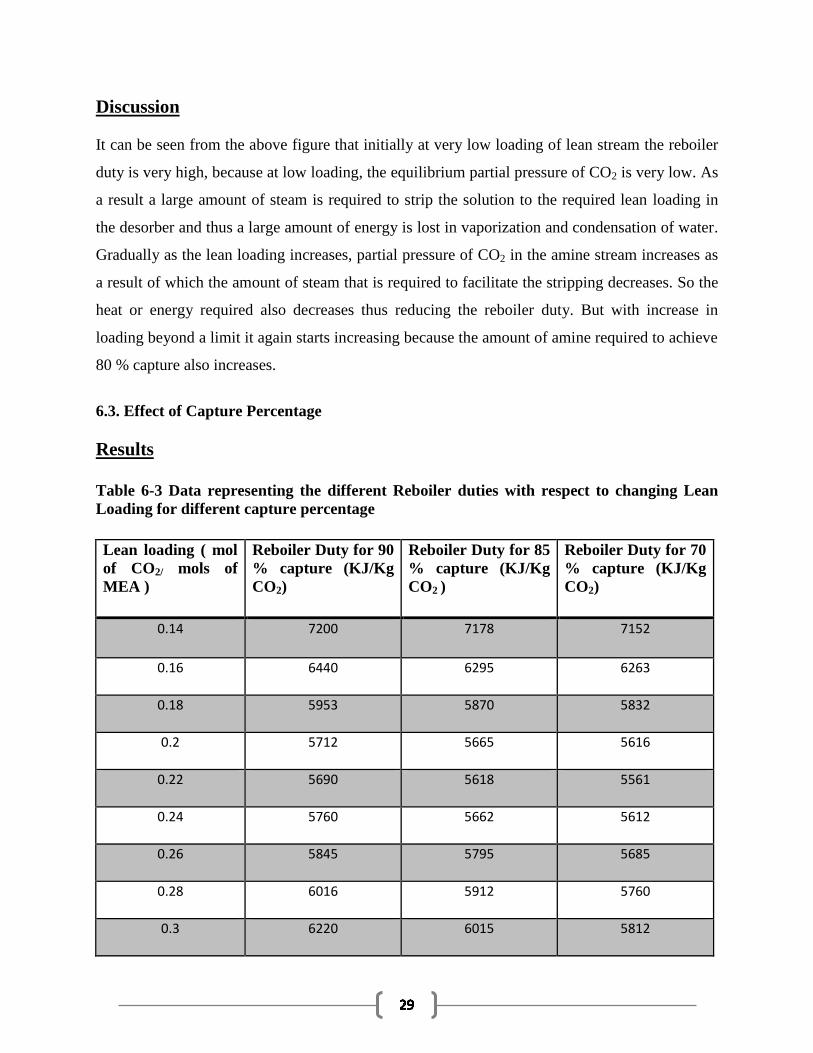
6.3. Effect of Capture Percentage
Results
Table 6-3 Data representing the different Reboiler duties with respect to changing Lean
Loading for different capture percentage
Lean loading ( mol
of CO2/ mols of
MEA )
Reboiler Duty for 90
% capture (KJ/Kg
CO2)
Reboiler Duty for 85
% capture (KJ/Kg
CO2 )
Reboiler Duty for 70
% capture (KJ/Kg
CO2)
0.14 7200 7178 7152
0.16 6440 6295 6263
0.18 5953 5870 5832
0.2 5712 5665 5616
0.22 5690 5618 5561
0.24 5760 5662 5612
0.26 5845 5795 5685
0.28 6016 5912 5760
0.3 6220 6015 5812
Graphical representation
Figure 6-3 Graph showing change in Reboiler Duty with Lean Loading for different
capture percentage
Discussion
The main purpose of any sequestration process is to enhance the amount of CO2 captured. Thus
the capture percentage is an important pre-requisite that should be kept in mind. Higher
percentage of capture requires more energy and a more efficient process. To verify this the
simulation was carried out at 3 different capture percentage – 90 , 85 , 70 and in each case the
variation of reboiler duty with lean loading was checked . The results are tabulated above and
from the figure 6-3 it can be clearly seen that the reboiler duty increases as we increase the
capture percentage. This occurs mainly because to achieve higher capture we need more solvent
and more heat which ultimately results in higher reboiler duty.
3000
3500
4000
4500
5000
5500
6000
6500
7000
7500
0 0.05 0.1 0.15 0.2 0.25 0.3 0.35
Reb
oile
r D
uty
( K
J/K
g )
Lean Loading ( mol of CO2/ mols of MEA )
Variation with Capture Percentage
Reboiler Duty for 90 % capture(KJ/Kg CO2)
Reboiler Duty for 85 % capture(KJ/Kg CO2 )
Reboiler Duty for 70 % capture(KJ/Kg CO2)
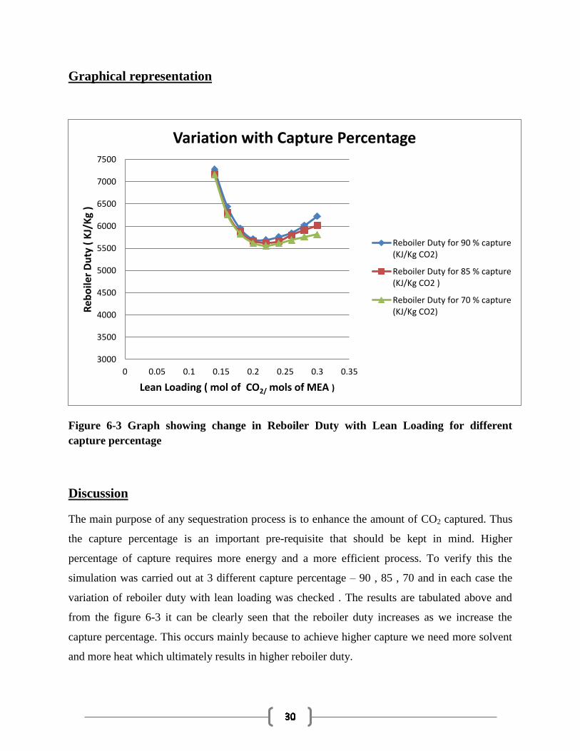
6.4. Effect of Desorber pressure on Reboiler Duty and Reboiler Temperature for 80 % CO2
capture.
Results Table 6-4 Data representing the values of Reboiler Duty and Temperature at different
Desorber Pressure
Desorber Pressure ( kpa ) Reboiler Duty (KJ/Kg) Reboiler Temperature (K)
75 7612 370
100 6548 378
125 6020 383
150 5860 387
175 5658 391
200 5510 394
225 5406 396
250 5312 399
275 4250 402
300 4200 405
Graphical Representation
Figure 6-4 Graph showing variation of Reboiler Duty with Desorber Pressure
3000
3500
4000
4500
5000
5500
6000
6500
7000
7500
8000
0 50 100 150 200 250 300 350
Reb
oile
r D
uty
(K
J/K
g)
Desorber Pressure ( kpa )
Reboiler Duty (KJ/Kg)
Reboiler Duty (KJ/Kg)
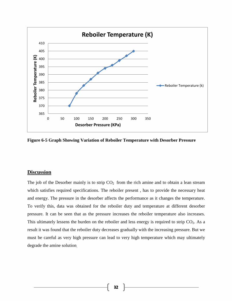
Figure 6-5 Graph Showing Variation of Reboiler Temperature with Desorber Pressure
Discussion
The job of the Desorber mainly is to strip CO2 from the rich amine and to obtain a lean stream
which satisfies required specifications. The reboiler present , has to provide the necessary heat
and energy. The pressure in the desorber affects the performance as it changes the temperature.
To verify this, data was obtained for the reboiler duty and temperature at different desorber
pressure. It can be seen that as the pressure increases the reboiler temperature also increases.
This ultimately lessens the burden on the reboiler and less energy is required to strip CO2. As a
result it was found that the reboiler duty decreases gradually with the increasing pressure. But we
must be careful as very high pressure can lead to very high temperature which may ultimately
degrade the amine solution.
365
370
375
380
385
390
395
400
405
410
0 50 100 150 200 250 300 350
Reb
oil
er T
emp
erat
ure
(K
)
Desorber Pressure (KPa)
Reboiler Temperature (K)
Reboiler Temperature (k)

6.5. Effect of approach temperature on the Reboiler Duty for varying Lean Loading
Results :-
Table 6-5 Data representing Reboiler Duties at different Lean Loading for 15oC and 10
oC
temperature approach
Lean Loading ( mol of
CO2 / mol of MEA)
Reboiler Duty For 15 O
C
Cross Heat Approach(KJ/Kg)
Reboiler Duty 10 O
C Cross
Heat Approach ( KJ/Kg)
0.1 9620 9620
0.12 8112 8112
0.14 7115 7115
0.16 6317 6317
0.18 5933 5889
0.2 5727 5665
0.22 5780 5632
0.24 5801 5653
0.26 5852 5702
0.28 5902 5755
0.3 5965 5806
Graphical Representation
Figure 6-6 Graph Showing Variation of Reboiler Duty due to different Cross heat
exchanger approach
3000
4000
5000
6000
7000
8000
9000
10000
0 0.1 0.2 0.3 0.4
Re
bo
ile
r D
uty
(K
J/K
g)
Lean Loading ( mol of CO2 / mol of MEA)
Reboiler Duty vs Cross Heat Exchanger Approach
Reboiler Duty For 15 OC CrossHeat Approach
Reboiler Duty 10 OC Cross HeatApproach
Discussion
The heat transfer between the Lean amine and Rich amine takes place through a cross heat
exchanger. We need a temperature approach for its proper functioning which also ultimately
affects its performance. The initial simulation was carried out using a 10 oC. When a higher
approach is selected it increases the heat requirements of the process. In the above analysis the
reboiler duties were generated assuming 10o
C and 15o
C temperature approach and these data
were plotted with respect to varying lean loading. It can be seen that at lower loadings there is
no change in the reboiler duty for both the cases. But as we increase the lean loading, the reboiler
duty also increases slightly to maintain a higher cross heat exchanger approach..
CHAPTER-7
7.1 CONCLUSION
From the work carried out it can be concluded that the simulation for the CO2-MEA-H2O system
is a complex process as it as a lot parameters which have to be taken care of. So initially we need
to carefully study the actual process and understand the different operations going on.
Accordingly the input specifications are to be provided that matches the relevant industrial
practices. The thermodynamic model used here is a simplified model which assumes the process
to be at equilibrium. The E-NRTL base method selected takes care of the presence of polar ions.
The different equilibrium reactions along with the different reaction parameters are also
necessary as they represent the mechanism and the components involved in the absorber and
desorber. To ensure the convergence of the open-loop flowsheet 5 design specifications have to
be incorporated. These also enable us to get a satisfying capture percentage. Later, to get a basic
idea about the effect of the parameters like solvent rate, capture percentage, desorber pressure on
the Reboiler Duty, Sensitivity analysis were carried out. From the results we could conclude that
as the lean loading increases the amount of amine required also increases but the reboiler duty
required decreases gradually. Similarly the variations of reboiler duty with capture percentage
and cross heat exchanger approach were also studied. The thermodynamic modeling does not
give the exact results but provides us the initial knowledge, the required methodology and
operation limits and values of different variable which will be used for more complex
simulations.
7.2 FUTURE COURSE OF WORK
In simulations carried out using thermodynamic model, the absorber and desorber column were
designed to consist of a set of stages, with each stage in equilibrium. The different reactions that
take place in the column were also assumed to be at equilibrium. But in reality the reactions are
not in equilibrium because mass transfer also takes place and the reaction kinetics, heat transfer
rate and mass transfer rate affect the process. Hence, these simulations present the most
optimistic results attainable. The main purpose of these simulations is to understand the complete
process and obtain good estimates of the different variables required for converging the system
with the more complex rate-based method. These simulations also give us an idea about the
effect; the different parameters have on the performance, but are unable to provide us with an
optimum value.
Using the input data and the results obtained from a successful equilibrium simulation, one can
easily work with a Rate Based Model It incorporates the phenomena of mass transfer , heat
transfer , solution kinetics and interface effect as well as the kinetics of chemical reactions and
film discretization , which explains the whole process going on . Also using the Rate-Frac Model
the dependency of the performance on loading, the packing characteristics, and the column
height can be found accurately. Also energy consumption is one of the main constraints of this
type of CO2 capture. So we can work on estimating the total energy requirement of the whole
plant and work on optimizing the whole process commercially.
REFERENCES
1. Intergovernmental Panel on Climate Change (IPCC), Summary for Policymakers. In: Climate
Change 2007: The Physical Science Basis, Cambridge University Press, 2007.
2. IPCC, IPCC Special Report on Carbon Dioxide Capture and Storage, B. Metz, et al., Editors.
2005.
3. Sridhar.S, Smitha. B,. Aminabhavi, T.M , Separation. Purification. Technology. 36 (2)
(2007) 113-174.
4. Davison, J., Bressan, L. and Domenichini, R. Carbon dioxide capture in coal-based IGCC
power plants. in Seventh International Conference on Greenhouse Gas Control Technologies.
2004. Vancouver, Canada.
5. L. Christopher, Capturing Carbon dioxide, International Energy Agency (IEA), Greenhouse Gas
R&D Programme 2007.
6. Bishnoi, S., CO2 Absorption and Solution Equilibrium in Piperzine Activated MDEA, Ph.D.
dissertation, The University of Texas at Austin, 2000
7. Dang, H., CO2 Absorption Rate and Solubility in Monoethanolamine/Piperzine/water, Master
Thesis , The University of Texas at Austin , 2001
8. Cullinane , J.T. , CO2 Absorption in Aqueous Mixture of K2CO3 and Piperzine , Master Thesis ,
The University of Texas at Austin , 2002
9. Caplow, M., Kinetics of carbamate formation and breakdown. Journal of the American
Chemical Society, 1969. 90(24): p. 6795-6803.
10. Crooks, J.E. and J.P. Donnellan, Kinetics and Mechanism of the Reaction between Carbon-
Dioxide and Amines in Aqueous-Solution. Journal of the Chemical Society-Perkin Transactions
2, 1989(4): p. 331-333.
11. Jou, F.Y., Mather, A.E., Otto, F.D., The solubility of CO2 in 30 Mass Percent
Monoethanolamine, Can .J. Chem Eng., 73, 1985, 140-147
12. Holmes, J.W., Spears, M.L., Bulin, J.A., Sweetening LPG’s with amines, Chem Eng. Project
80(5), 1984, 47-50
13. Zheng , D.P., Ng , H.J., Modeling of Liquid hydrocarbon sweetening with amine solutions ,
Process., Annual Conventional Gas Process Association , 75th
, 1996 , 22-26
14. Rao, A., E. Rubin, and M. Berkenpas, An Integrated Modeling Framework for Carbon
Management Technologies - Volume 1 - Technical Documentation: Amine Based CO2 Capture
and Storage Systems for Fossil Fuel Power Plant, C.M.U. Department of Engineering and Public
Policy, Editor. 2004
15. Reddy, S., J. Scherffius, S. Freguia, and R. C., Fluor's EconamineTM FG PlusSM
Technology: An Enhanced Amine-Based CO2 Capture Process, in Second National Conference
on Carbon Sequestration. 2003: Alexandria, VA.
16. Andersson, K. and F. Johnsson, Process evaluation of an 865 MWe lignite fired O2/CO2
power plant. Energy Conversion and Management, 2006. 47(18-19): p. 3487-3498.
17. VGB PowerTech, CO2 Capture and Storage: VGB Report on the State of the Art.2004
18. Augsten, D.M., A model for vapor-liquid equilibria for acid gas-alkanolamine-H2O systems,
in Chemical Engineering., University of Texas at Austin: Austin. , 1989
19. Rochelle, G., S. Bishnoi, S. Chi, H. Dang, and J. Santos, Research Needs for CO2 Capture
from Flue Gas by Aqueous Absorption/Stripping., University of Texas at Austin: Austin. , 2001
20. Chen, C.-C., H.I. Britt, J.F. Boston, and L.B. Evans, Local composition model for excess
Gibbs energy of electrolyte systems. Part I: Single solvent, single completely dissociated
electrolyte systems. AIChE Journal, 1982. 28(4): p. 588-596
21. Augsten, D.M., Rochelle , G.T., Chen C.C., A model for vapor-liquid equilibrium for
aqueous acid gas-alkanolamine-H2O systems using Electrolyte-NRTL Equations, in Chemical
Engineering. Ind. Eng. Chem Res., 28(7) , 1989
.
22. Freguia, S., Modeling of CO2 Removal from Flue Gases with Monoethanolamine, in
Chemical Engineering., University of Texas at Austin: Austin. , 2002: p. 9-16
23. ASPEN, User Online Documentation. 2008.
24. Zhang, Y., H. Chen, C.-C. Chen, J.M. Plaza, R. Dugas, and G.T. Rochelle, Rate- Based
Process Modeling Study of CO2 Capture with Aqueous Monoethanolamine Solution. Industrial
& Engineering Chemistry Research, 48(20): 2009 , p. 9233- 9246.
25. Kothadaraman , A. , Carbon Dioxide Capture by Chemical Absorption : - A Solvent
Comparison Study , Ph.D. dissertation , Massachusetts Institute of Technology , 2010