Embed Size (px)
Citation preview

Power Electronics CircuitsProf. Daniel Costinett
ECE 482 Lecture 4February 20, 2018
Simulation Modeling
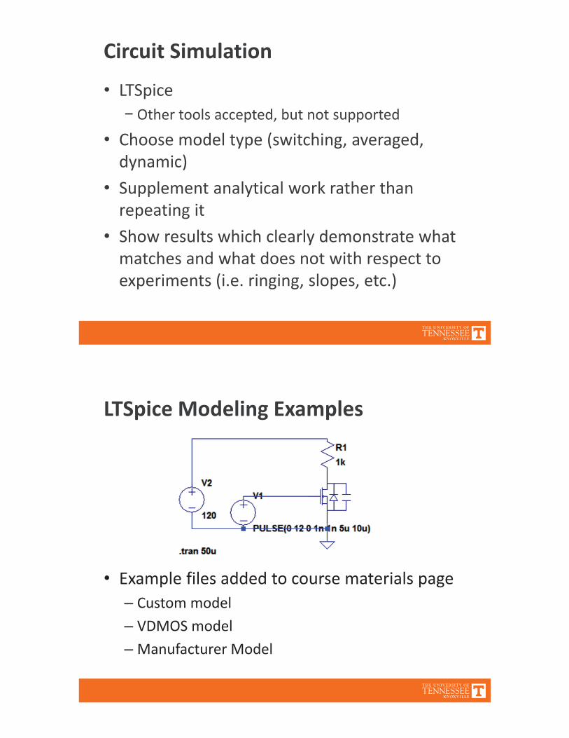
Circuit SimulationLTSpice
Other tools accepted, but not supportedChoose model type (switching, averaged,dynamic)Supplement analytical work rather thanrepeating itShow results which clearly demonstrate whatmatches and what does not with respect toexperiments (i.e. ringing, slopes, etc.)
LTSpice Modeling Examples
Example files added to course materials pageCustom modelVDMOS modelManufacturer Model
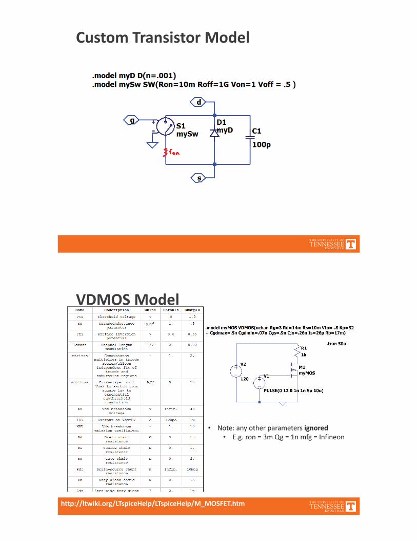
Custom Transistor Model
VDMOS Model
http://ltwiki.org/LTspiceHelp/LTspiceHelp/M_MOSFET.htm
Note: any other parameters ignoredE.g. ron = 3m Qg = 1n mfg = Infineon
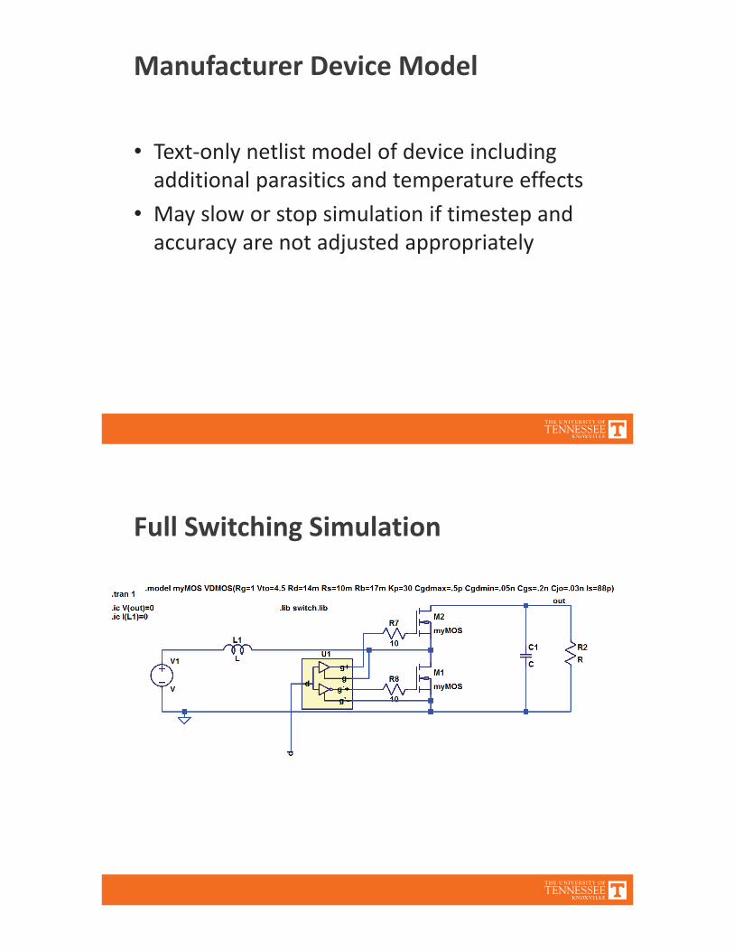
Manufacturer Device Model
Text only netlist model of device includingadditional parasitics and temperature effectsMay slow or stop simulation if timestep andaccuracy are not adjusted appropriately
Full Switching Simulation
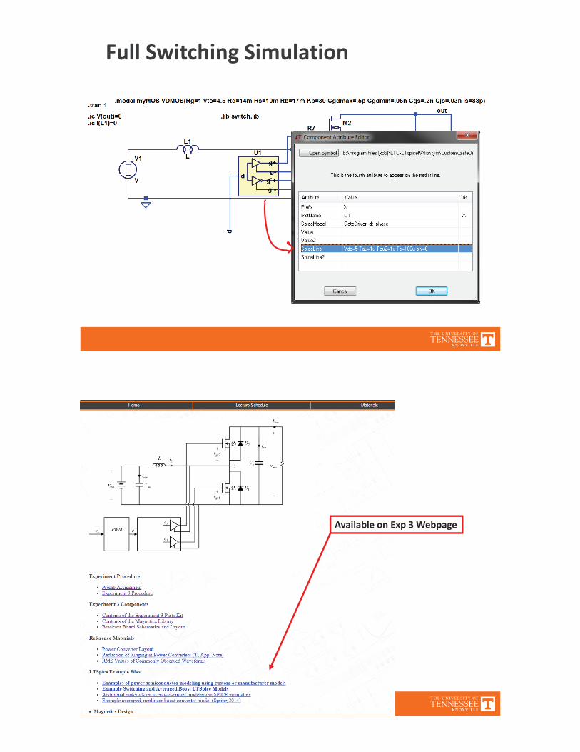
Full Switching Simulation
Available on Exp 3 Webpage
Full Switching ModelGives valuable insight into circuit operation
Understand expected waveformsIdentify discrepancies between predicted andexperimental operation
Slow to simulate; significant high frequencycontentCannot perform AC analysis
Averaged Switch Modeling: Motivation
A large signal, nonlinear model of converter isdifficult for hand analysis, but well suited tosimulation across a wide range of operatingpointsWant an averagedmodel to speed upsimulation speedAlso allows linearization (AC analysis) forcontrol design
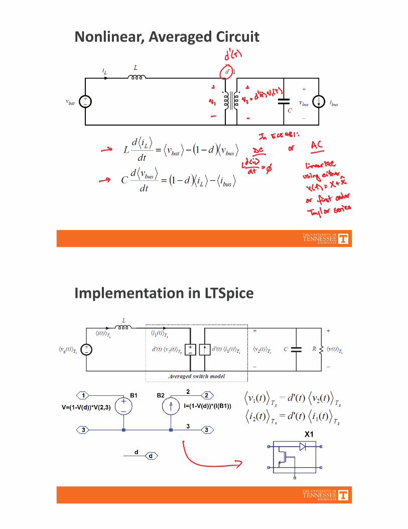
Nonlinear, Averaged Circuit
Implementation in LTSpice
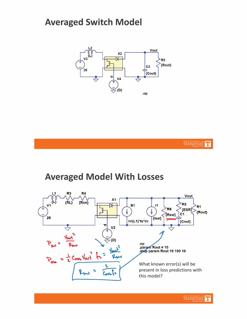
Averaged Switch Model
Averaged Model With Losses
What known error(s) will bepresent in loss predictions withthis model?
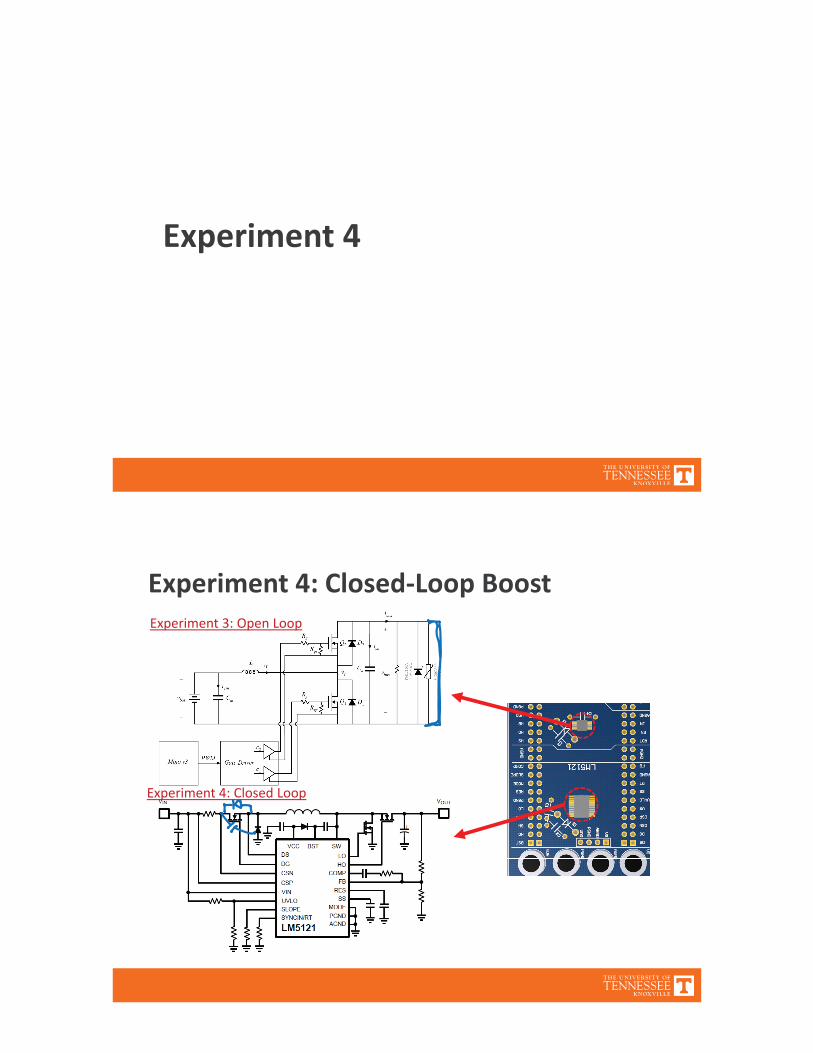
Experiment 4
Experiment 4: Closed Loop BoostExperiment 3: Open Loop
Experiment 4: Closed Loop
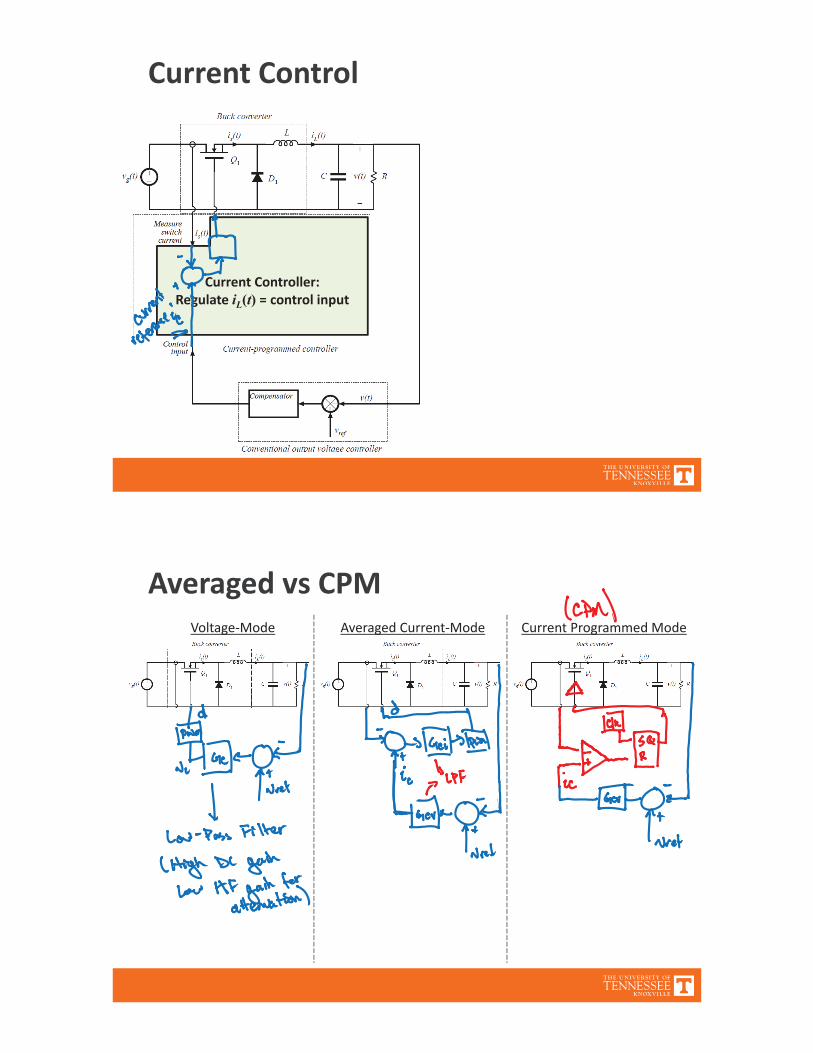
Current Control
Current Controller:Regulate iL t = control input
Averaged vs CPMAveraged Current ModeVoltage Mode Current Programmed Mode
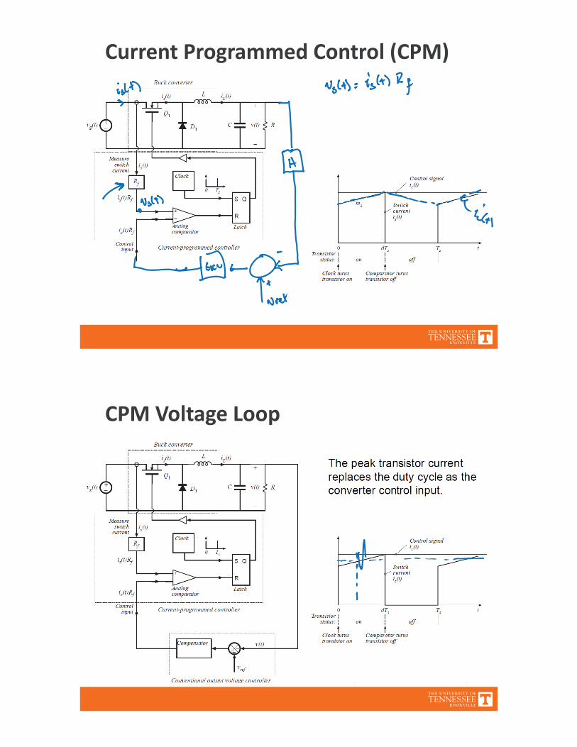
Current Programmed Control (CPM)
CPM Voltage Loop

Current Programmed ControlCovered in Ch. 12 of Fundamentals of PowerElectronicsAdvantages of current programmed control:
Simpler dynamics —inductor pole is moved to highfrequencySimple robust output voltage control, with large phasemargin, can be obtained without use of compensator leadnetworksTransistor failures due to excessive current can beprevented simply by limiting ic(t)It is always necessary to sense the transistor current, toprotect against overcurrent failuresTransformer saturation problems in bridge or push pullconverters can be mitigated
A disadvantage: susceptibility to noise
A Simple First Order Model
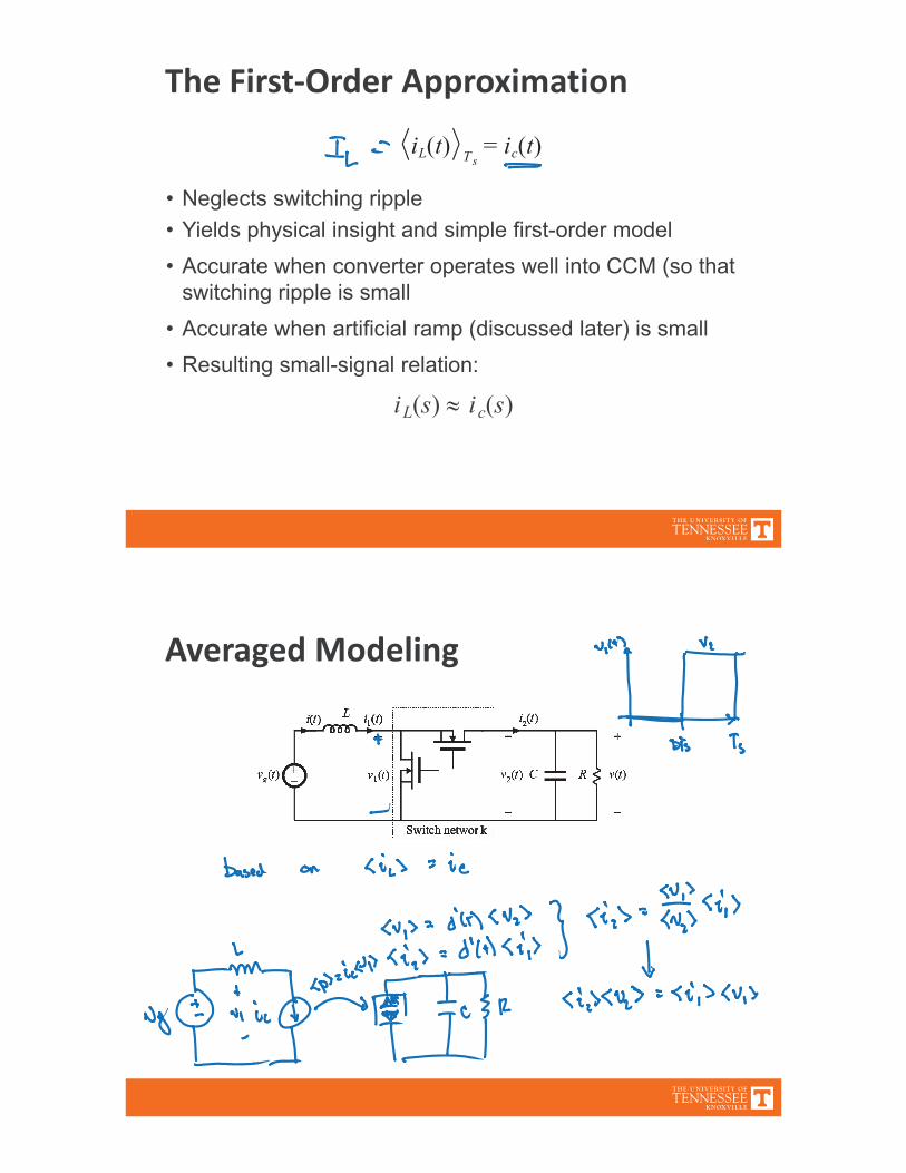
The First Order Approximation
iL s ic s
iL t ic tTs
Averaged Modeling
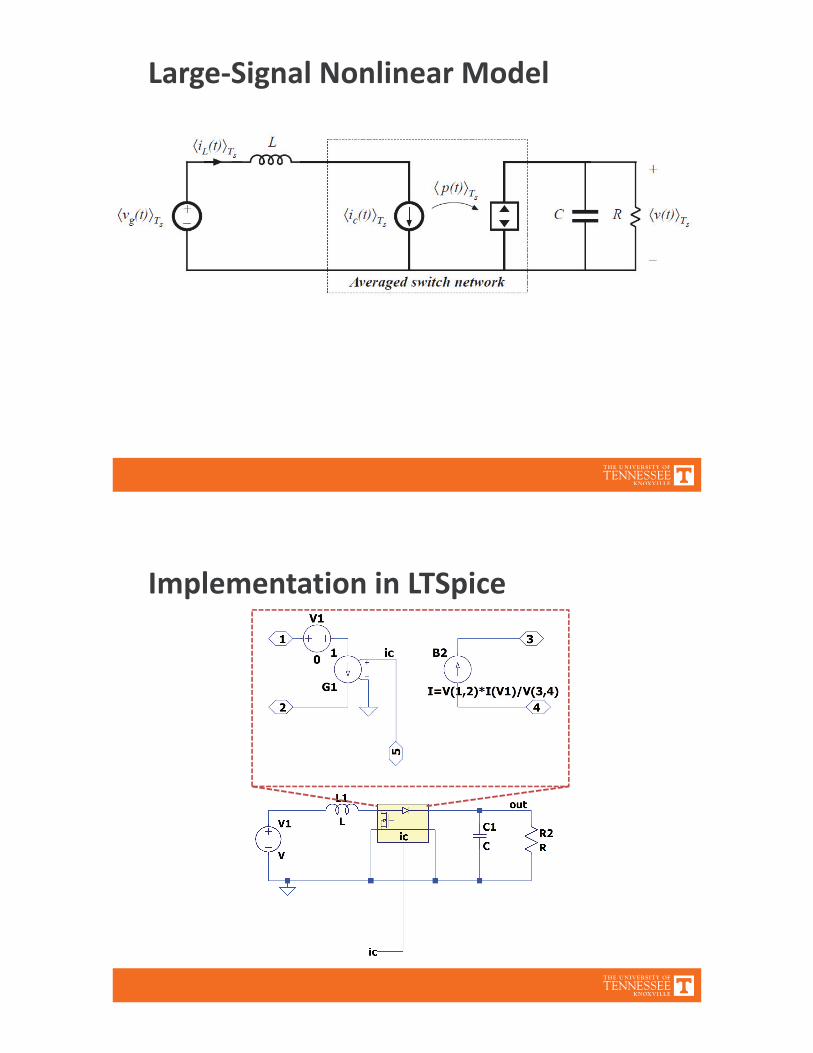
Large Signal Nonlinear Model
Implementation in LTSpice
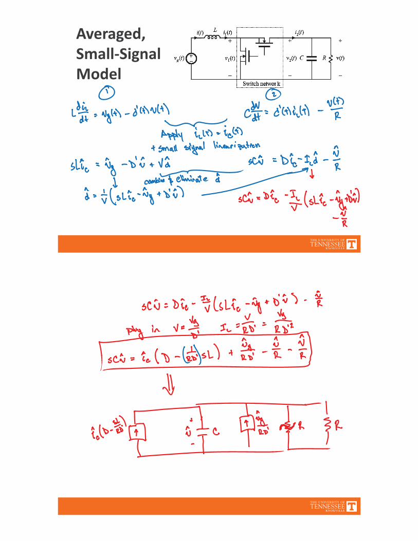
Averaged,Small SignalModel
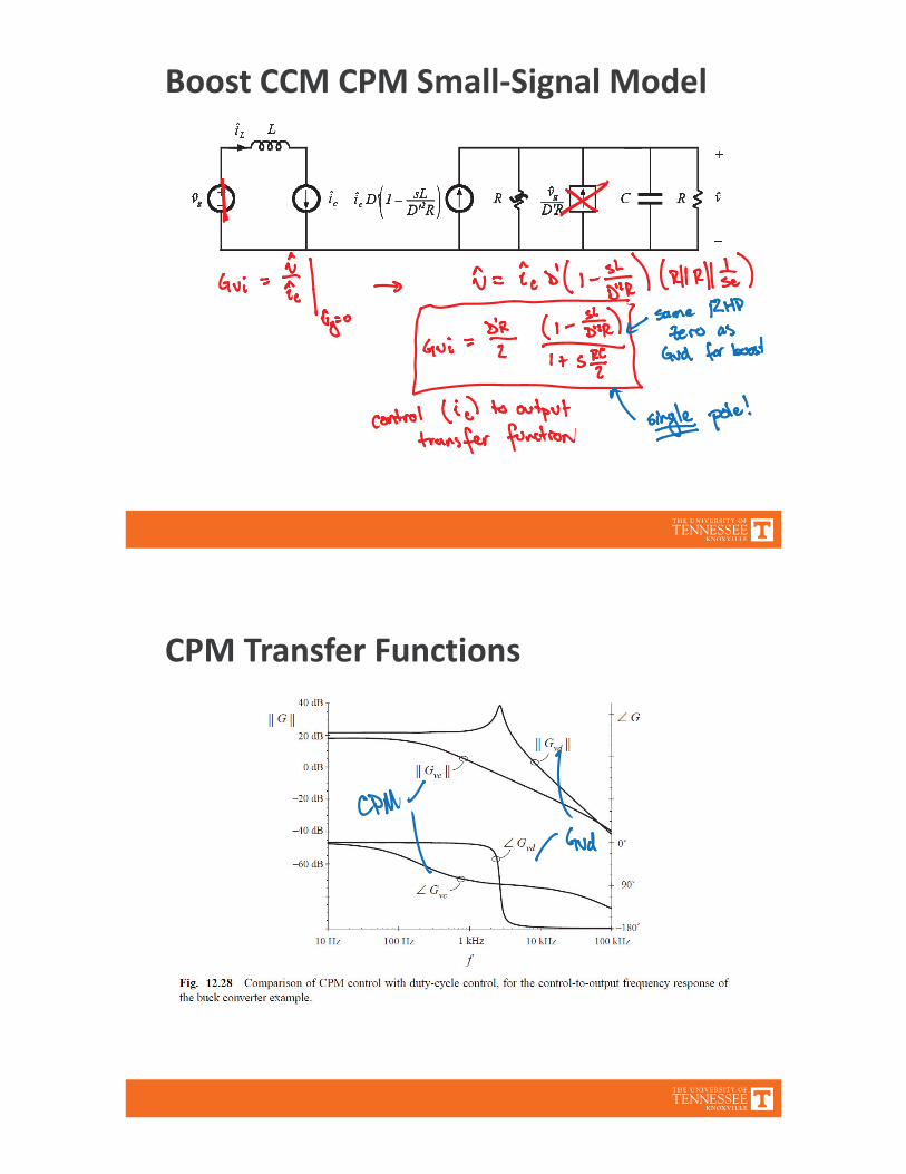
Boost CCM CPM Small Signal Model
CPM Transfer Functions
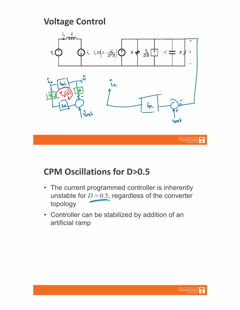
Voltage Control
CPM Oscillations for D>0.5
D
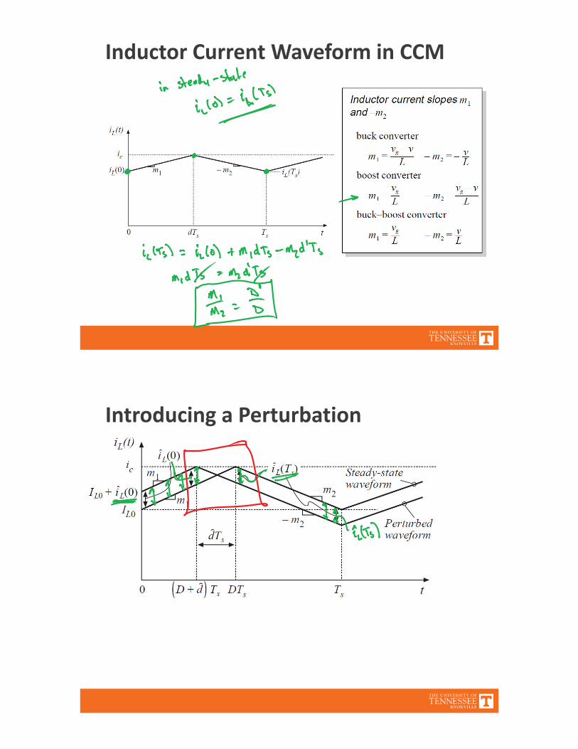
Inductor Current Waveform in CCM
Introducing a Perturbation

Change in Inductor Current Over Ts
Example: Unstable operation for D=0.6

Example: Stable operation for D=1/3
Stabilization Through Artificial Ramp

Final Value of Inductor Current
Artificial Ramp: Additional NotesFor stability, require | |<1Common choices:ma mma m
Artificial ramp decreases sensitivity to noise

More Accurate ModelsThe simple models of the previous section yield insightinto the low frequency behavior of CPM convertersUnfortunately, they do not always predict everythingthat we need to know:
Line to output transfer function of the buck converterDynamics at frequencies approaching fs
More accurate model accounts for nonideal operationof current mode controller built in feedback loopConverter duty cycle controlled model, plus blockdiagram that accurately models equations of currentmode controllerSee Section 12.3 for additional info
More Accurate ModelSimple model assumes alwaysAccounting for ripple, and artificial rampweakens this approximationUsing sampled data modeling
Where
F. Dong Tan and R. D. Middlebrook, “A Unified Model for Current Programmed Converters,” IEEETransactions on Power Electronics, vol. 10, no. 4, July 1995.

Note: Comparison to Datasheet
Application to Experiment 4
Complex switching controllerRead the datasheet first
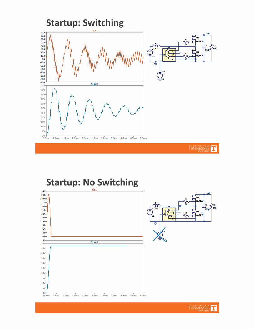
Startup: Switching
Startup: No Switching
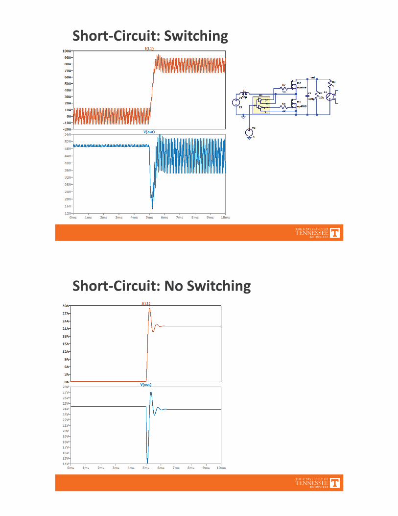
Short Circuit: Switching
Short Circuit: No Switching
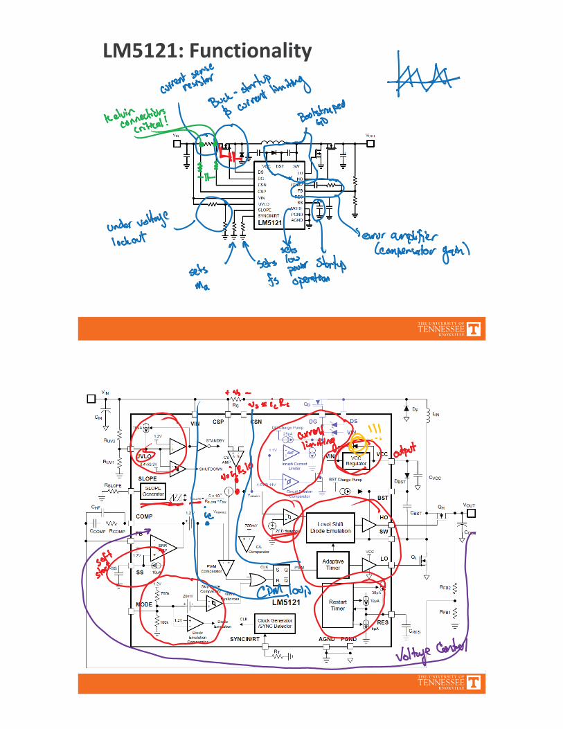
LM5121: Functionality
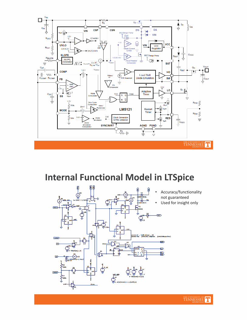
Internal Functional Model in LTSpiceAccuracy/functionalitynot guaranteedUsed for insight only
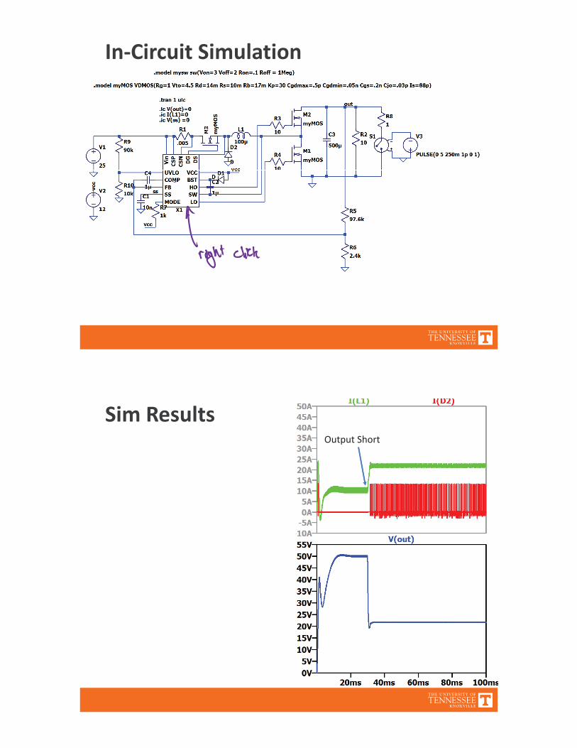
In Circuit Simulation
Sim ResultsOutput Short
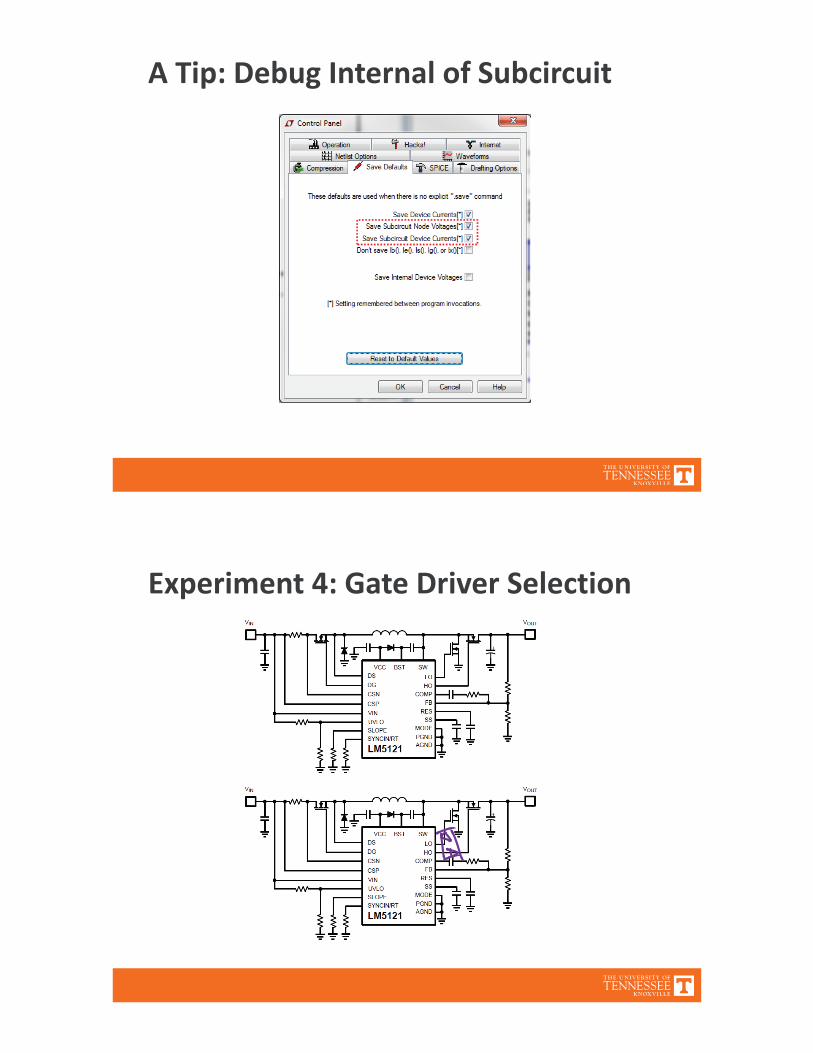
A Tip: Debug Internal of Subcircuit
Experiment 4: Gate Driver Selection
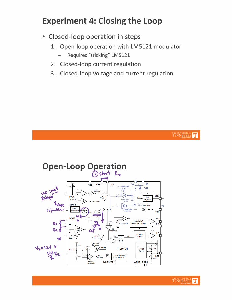
Experiment 4: Closing the LoopClosed loop operation in steps1. Open loop operation with LM5121 modulator
– Requires “tricking” LM51212. Closed loop current regulation3. Closed loop voltage and current regulation
Open Loop Operation
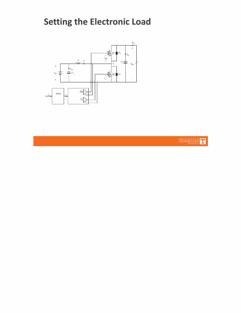
Setting the Electronic Load