Embed Size (px)
Citation preview
Simulation Environment“SimVis3D”
Syed Atif Mehdi
Robotics Research Lab
Department of Computer Science
University of Kaiserslautern
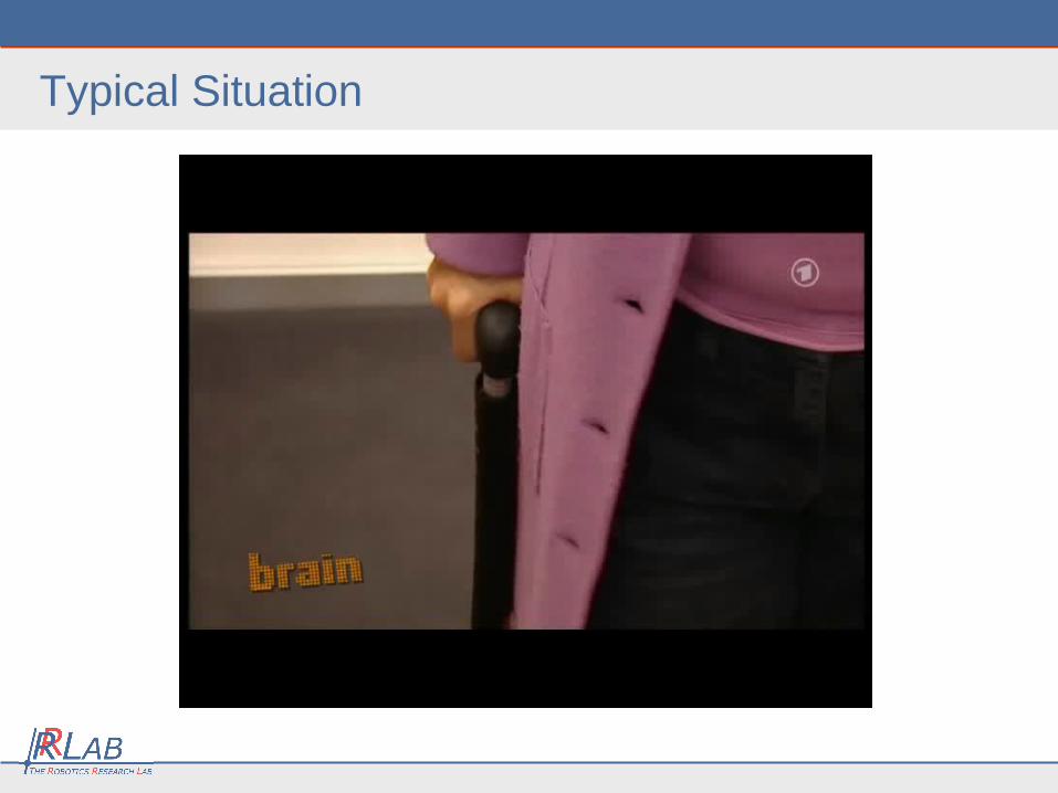
Typical Situation
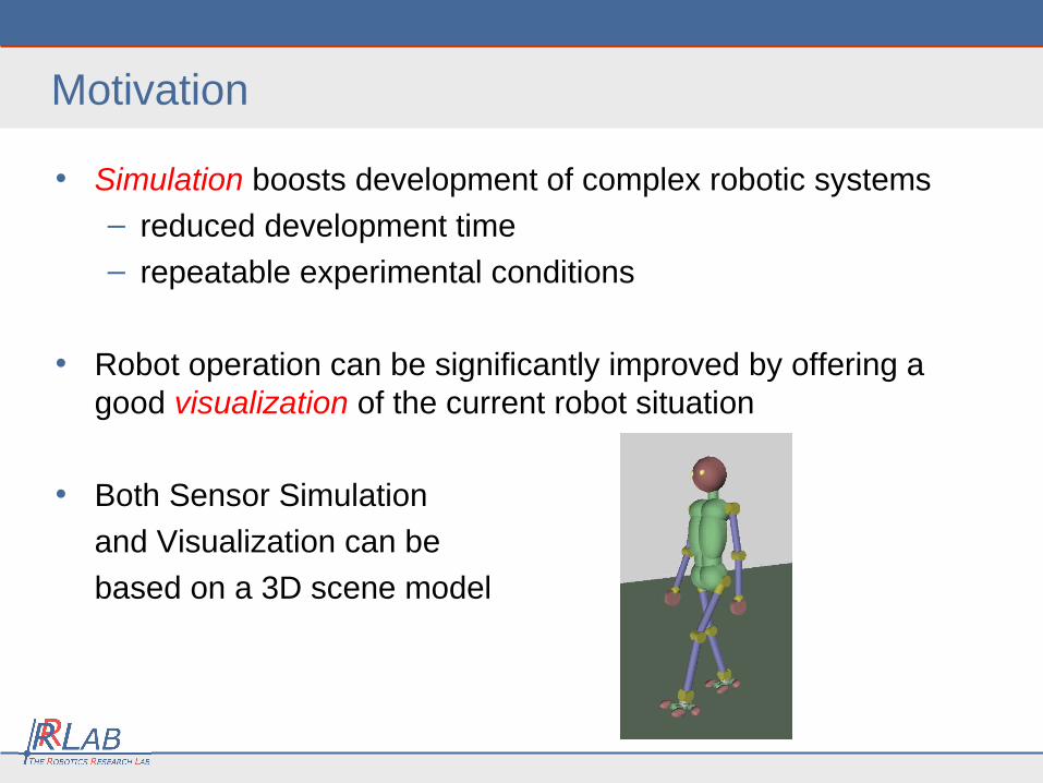
Motivation
• Simulation boosts development of complex robotic systems
– reduced development time
– repeatable experimental conditions
• Robot operation can be significantly improved by offering a good visualization of the current robot situation
• Both Sensor Simulation
and Visualization can be
based on a 3D scene model
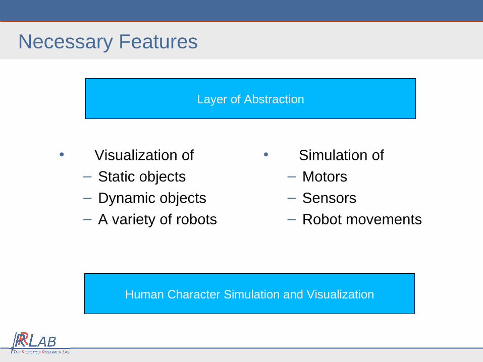
Necessary Features
• Visualization of
– Static objects
– Dynamic objects
– A variety of robots
Human Character Simulation and Visualization
Layer of Abstraction
• Simulation of
– Motors
– Sensors
– Robot movements
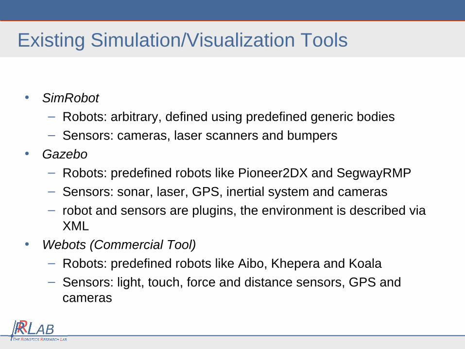
Existing Simulation/Visualization Tools
• SimRobot
– Robots: arbitrary, defined using predefined generic bodies– Sensors: cameras, laser scanners and bumpers
• Gazebo– Robots: predefined robots like Pioneer2DX and SegwayRMP– Sensors: sonar, laser, GPS, inertial system and cameras– robot and sensors are plugins, the environment is described via
XML
• Webots (Commercial Tool)– Robots: predefined robots like Aibo, Khepera and Koala – Sensors: light, touch, force and distance sensors, GPS and
cameras
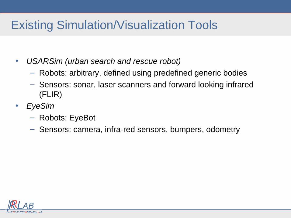
Existing Simulation/Visualization Tools
• USARSim (urban search and rescue robot)
– Robots: arbitrary, defined using predefined generic bodies– Sensors: sonar, laser scanners and forward looking infrared
(FLIR)
• EyeSim
– Robots: EyeBot
– Sensors: camera, infra-red sensors, bumpers, odometry
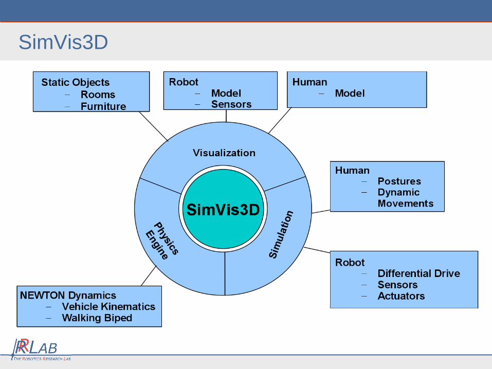
SimVis3D
Contribution
• Existing tools
– good for typical scenarios and robots
– inadequate for highly specific, unforeseen demands
• e.g. foilage transparency in an outdoor environment
– distribution across multiple hosts is not well supported
• We propose a framework for sensor simulation and visualization (SimVis3D) with three main characteristics:
– open source
– modular – easily extendable
– multiple hosts can interact with the framework in real-time
SimVis3D Architecture
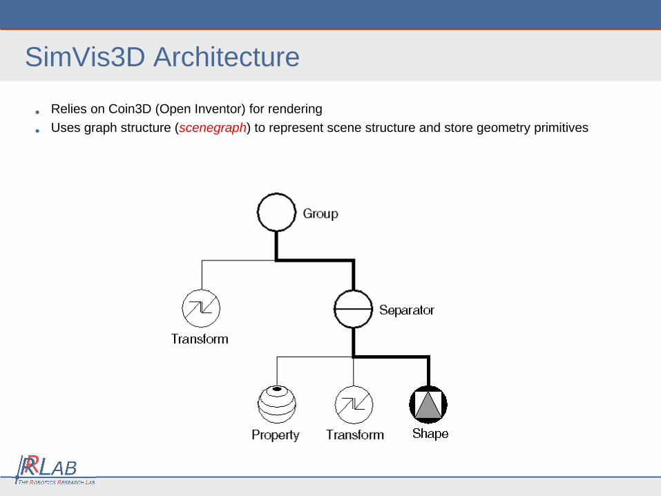
• Relies on Coin3D (Open Inventor) for rendering
• Uses graph structure (scenegraph) to represent scene structure and store geometry primitives
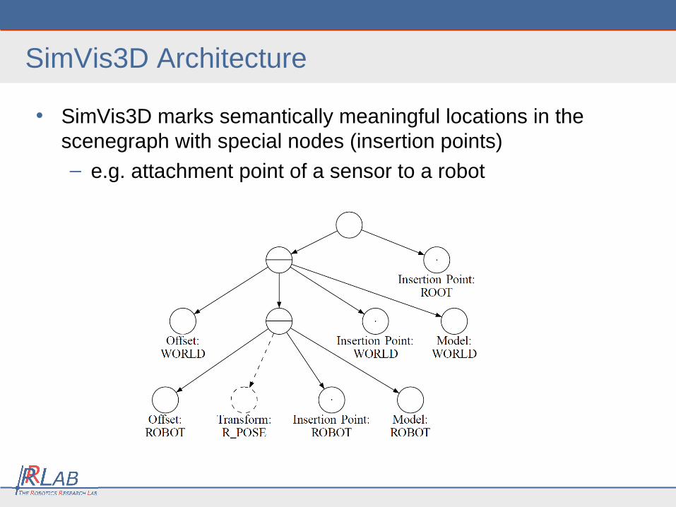
• SimVis3D marks semantically meaningful locations in the scenegraph with special nodes (insertion points)
– e.g. attachment point of a sensor to a robot
SimVis3D Architecture
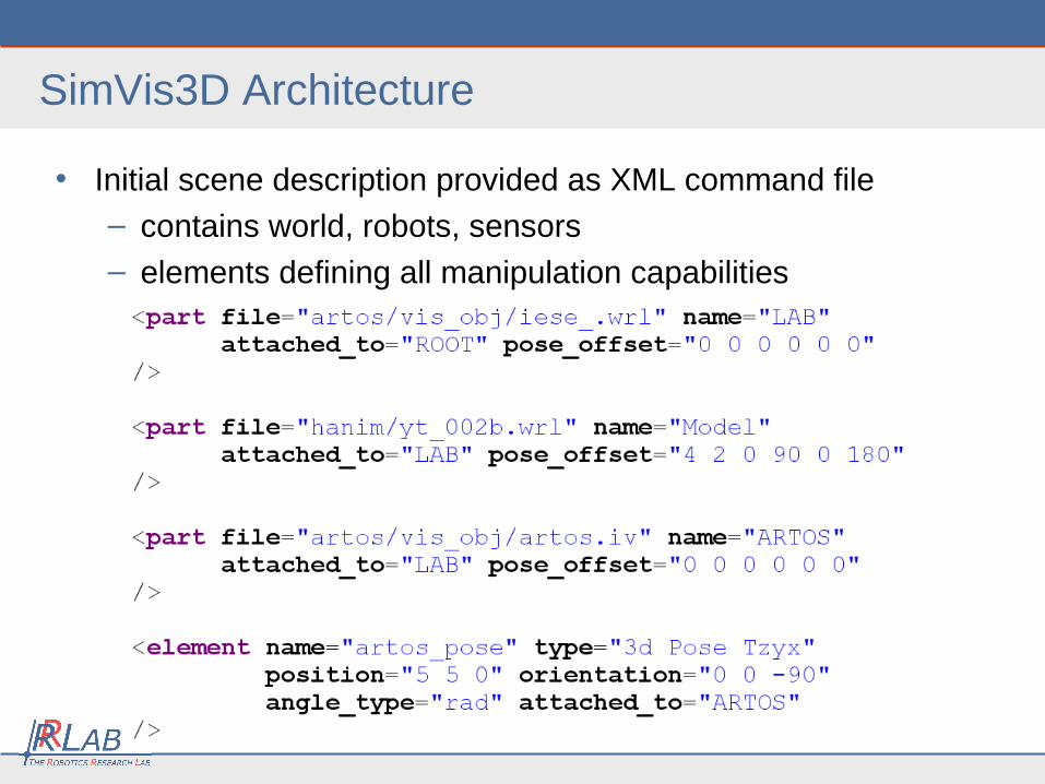
• Initial scene description provided as XML command file
– contains world, robots, sensors
– elements defining all manipulation capabilities
SimVis3D Architecture
Scene Construction
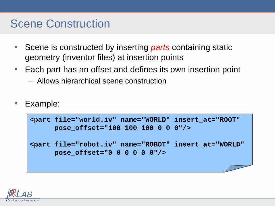
• Scene is constructed by inserting parts containing static geometry (inventor files) at insertion points
• Each part has an offset and defines its own insertion point– Allows hierarchical scene construction
• Example:
<part file="world.iv" name="WORLD" insert_at="ROOT" pose_offset="100 100 100 0 0 0"/>
<part file="robot.iv" name="ROBOT" insert_at="WORLD" pose_offset="0 0 0 0 0 0"/>
Elements
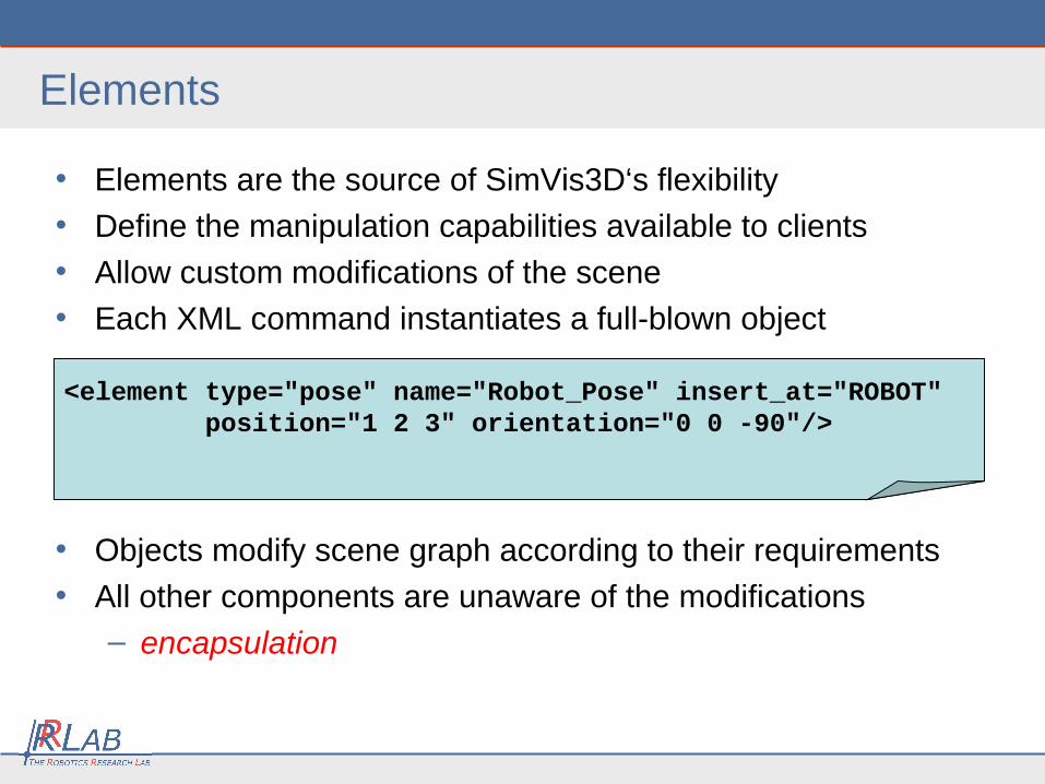
• Elements are the source of SimVis3D‘s flexibility
• Define the manipulation capabilities available to clients
• Allow custom modifications of the scene
• Each XML command instantiates a full-blown object
• Objects modify scene graph according to their requirements
• All other components are unaware of the modifications
– encapsulation
<element type="pose" name="Robot_Pose" insert_at="ROBOT" position="1 2 3" orientation="0 0 -90"/>
Manipulating Elements
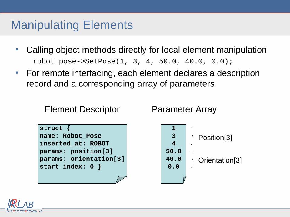
• Calling object methods directly for local element manipulation robot_pose->SetPose(1, 3, 4, 50.0, 40.0, 0.0);
• For remote interfacing, each element declares a description record and a corresponding array of parameters
Element Descriptor Parameter Array
Position[3]
Orientation[3]
struct {name: Robot_Poseinserted_at: ROBOTparams: position[3]params: orientation[3]start_index: 0 }
134
50.040.00.0
Sensors
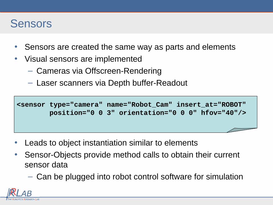
• Sensors are created the same way as parts and elements
• Visual sensors are implemented
– Cameras via Offscreen-Rendering
– Laser scanners via Depth buffer-Readout
• Leads to object instantiation similar to elements
• Sensor-Objects provide method calls to obtain their current sensor data
– Can be plugged into robot control software for simulation
<sensor type="camera" name="Robot_Cam" insert_at="ROBOT" position="0 0 3" orientation="0 0 0" hfov="40"/>
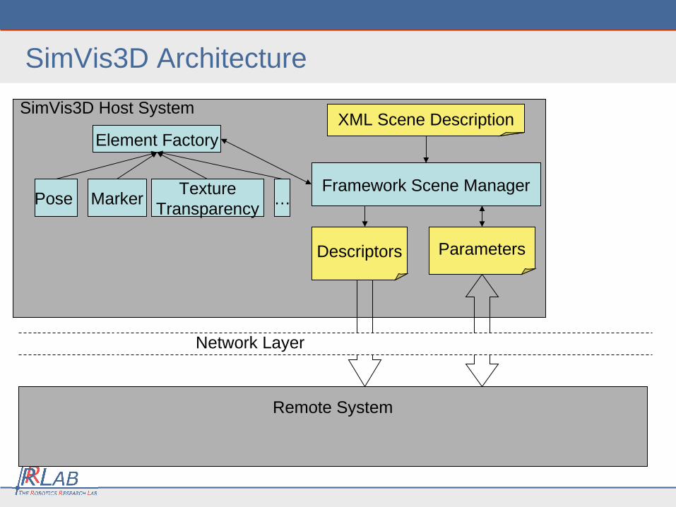
SimVis3D Host System
SimVis3D Architecture
Framework Scene Manager
Element Factory
Pose MarkerTexture
Transparency…
XML Scene Description
Descriptors Parameters
Network Layer
Remote System
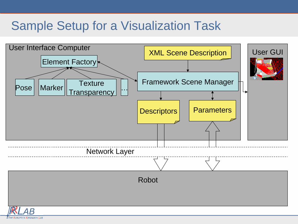
User Interface Computer
Sample Setup for a Visualization Task
Framework Scene Manager
Element Factory
Pose MarkerTexture
Transparency…
XML Scene Description
Descriptors Parameters
Network Layer
Robot
User GUI
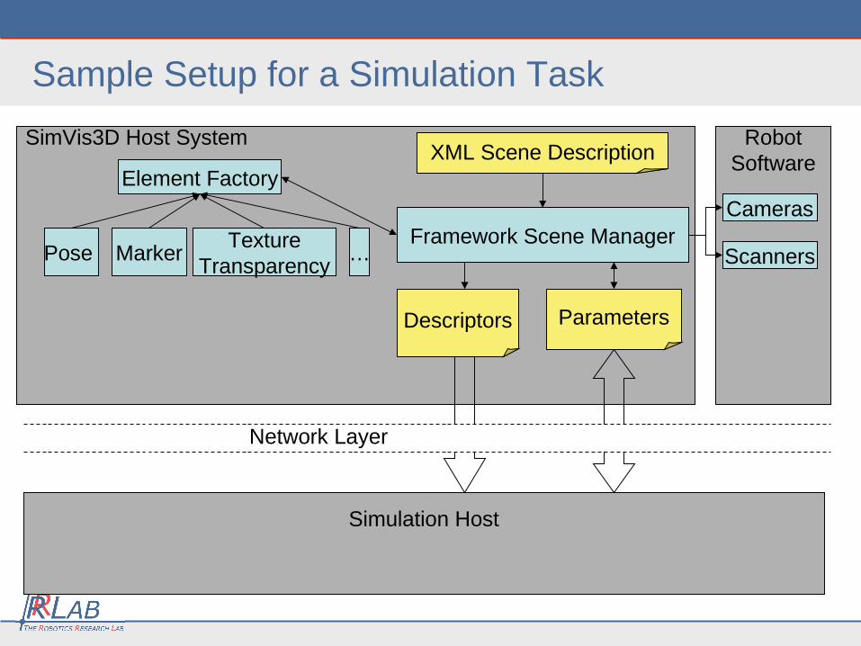
SimVis3D Host System
Sample Setup for a Simulation Task
Framework Scene Manager
Element Factory
Pose MarkerTexture
Transparency…
XML Scene Description
Descriptors Parameters
Network Layer
Simulation Host
RobotSoftware
Cameras
Scanners
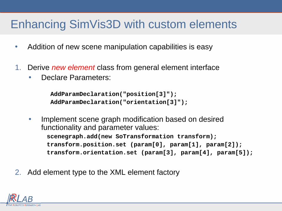
Enhancing SimVis3D with custom elements
• Addition of new scene manipulation capabilities is easy
1. Derive new element class from general element interface• Declare Parameters: AddParamDeclaration("position[3]"); AddParamDeclaration("orientation[3]");
• Implement scene graph modification based on desired functionality and parameter values:
scenegraph.add(new SoTransformation transform); transform.position.set (param[0], param[1], param[2]); transform.orientation.set (param[3], param[4], param[5]);
2. Add element type to the XML element factory
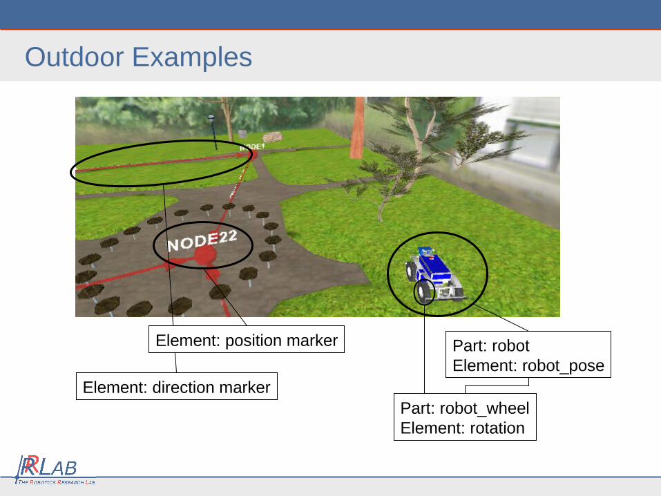
Outdoor Examples
Part: robotElement: robot_pose
Part: robot_wheelElement: rotation
Element: direction marker
Element: position marker
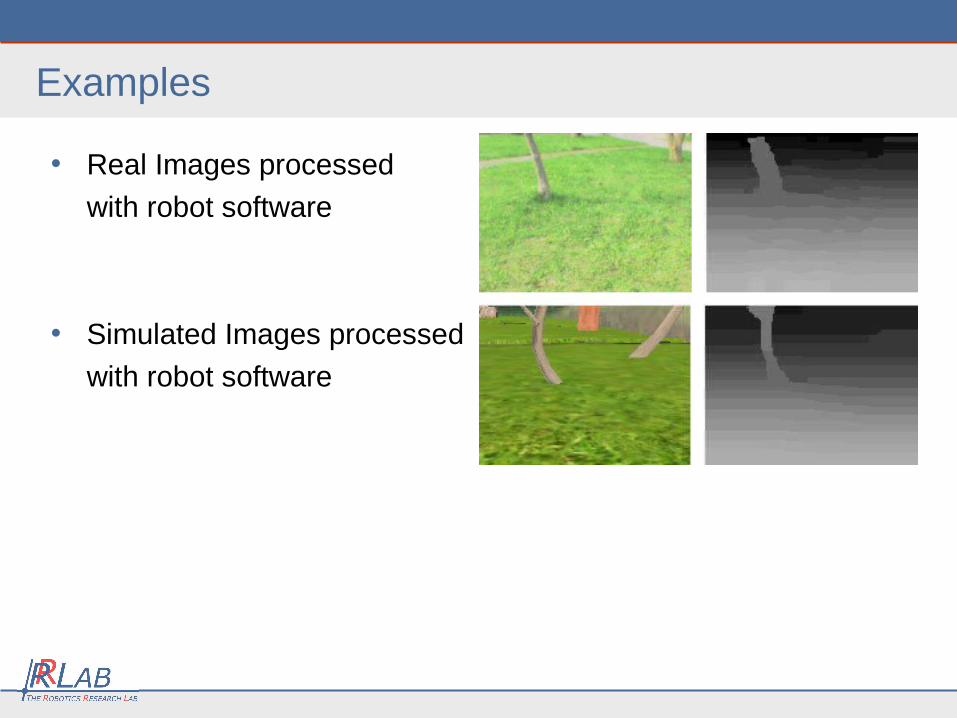
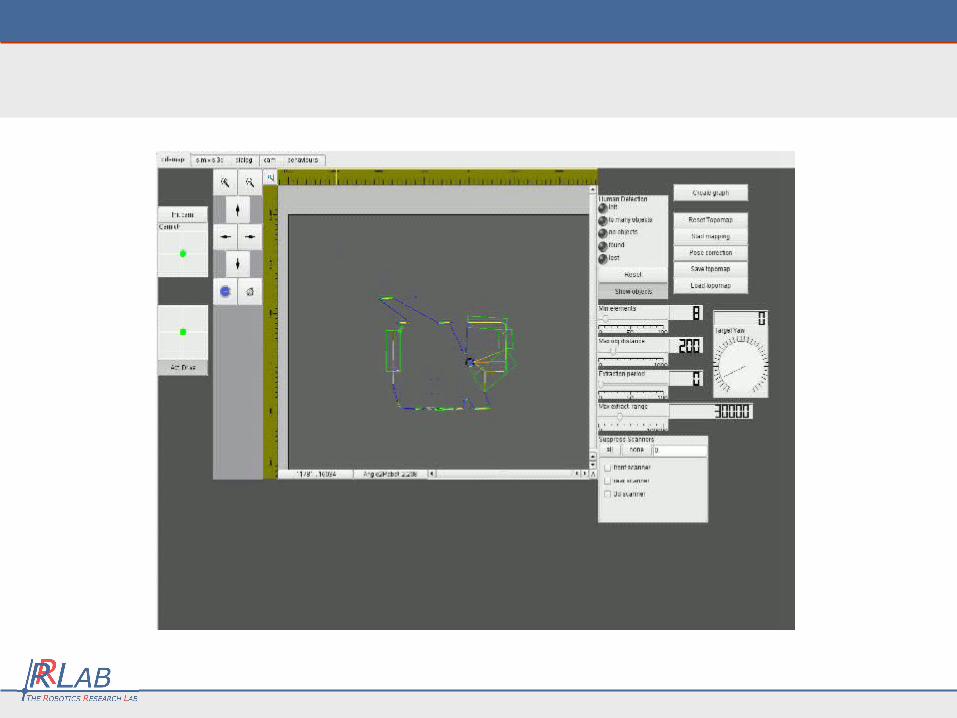
Examples
• Real Images processed
with robot software
• Simulated Images processed
with robot software
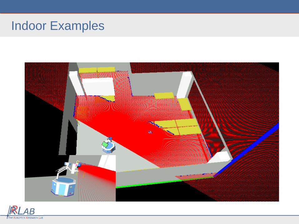
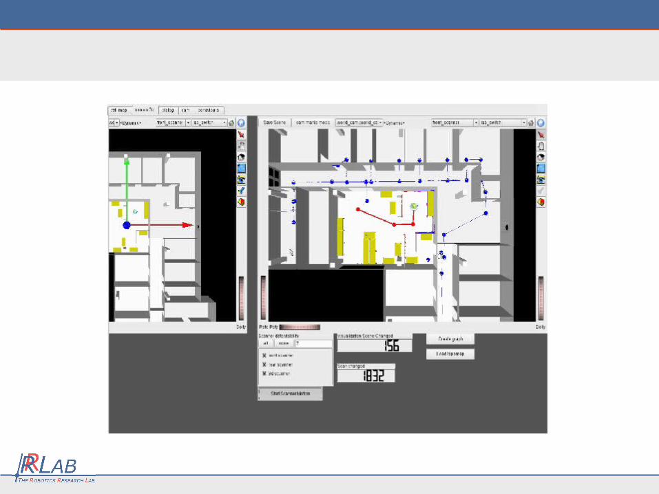
Indoor Examples
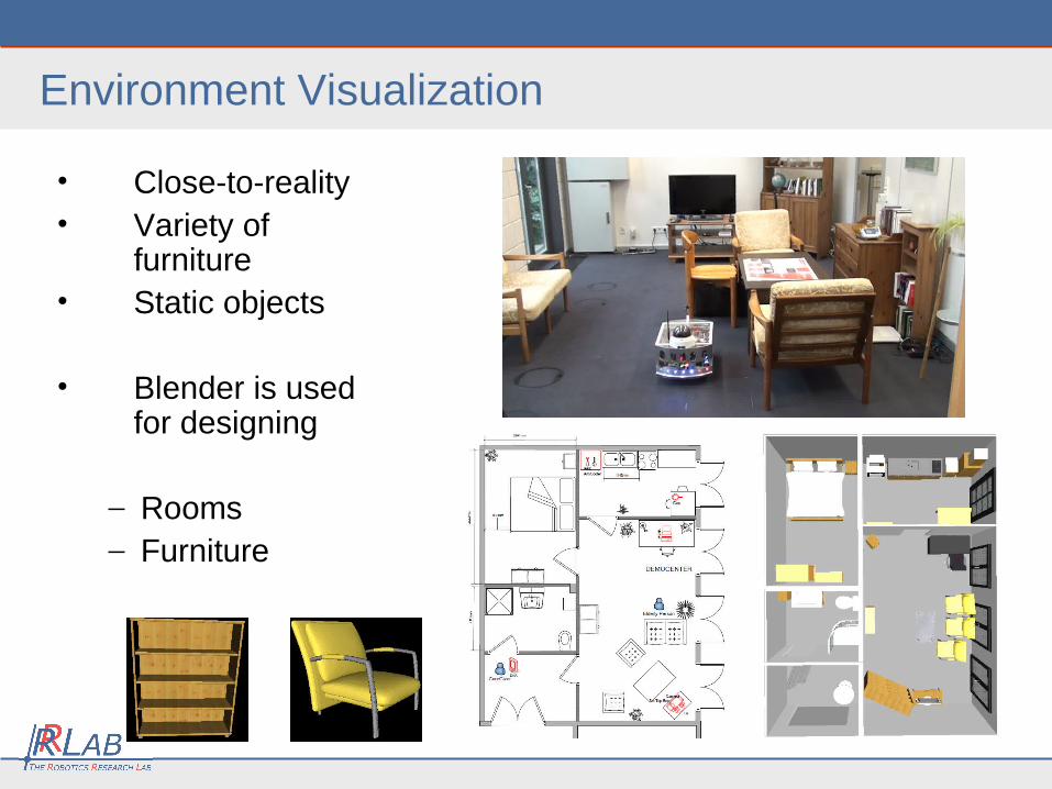
• Close-to-reality• Variety of
furniture• Static objects
• Blender is used for designing
– Rooms– Furniture
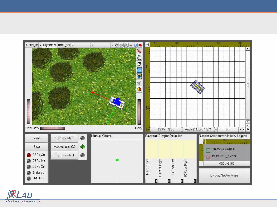
Environment Visualization
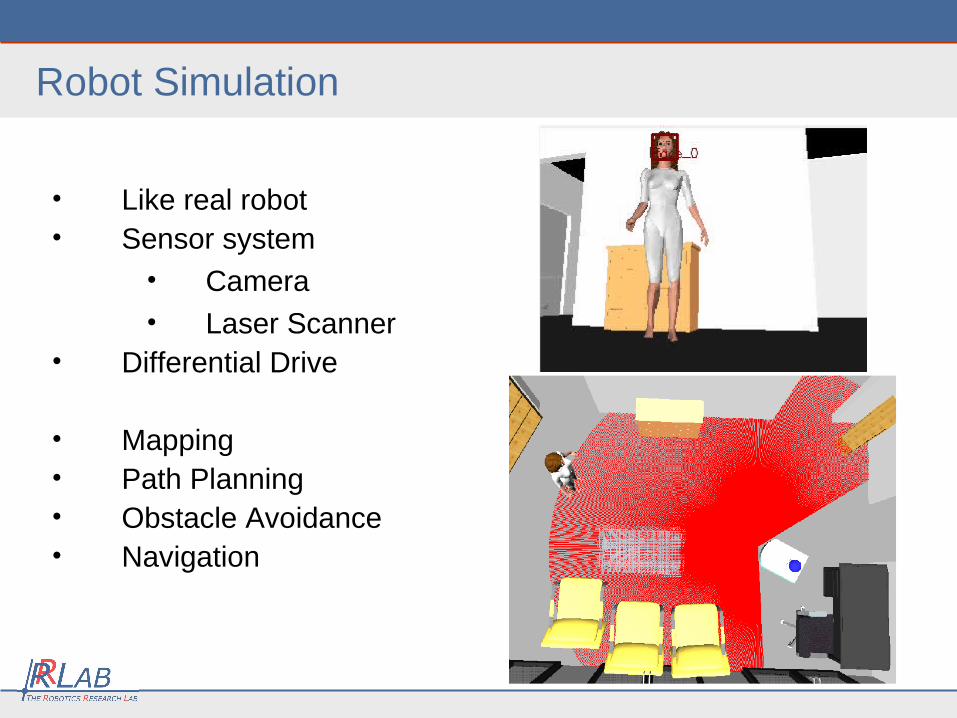
• Like real robot• Sensor system
• Camera• Laser Scanner
• Differential Drive
• Mapping • Path Planning• Obstacle Avoidance• Navigation
Robot Simulation
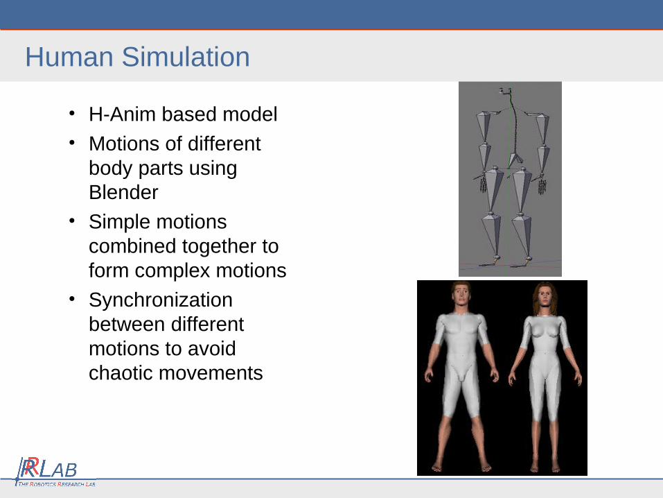
• H-Anim based model• Motions of different
body parts using Blender
• Simple motions combined together to form complex motions
• Synchronization between different motions to avoid chaotic movements
Human Simulation
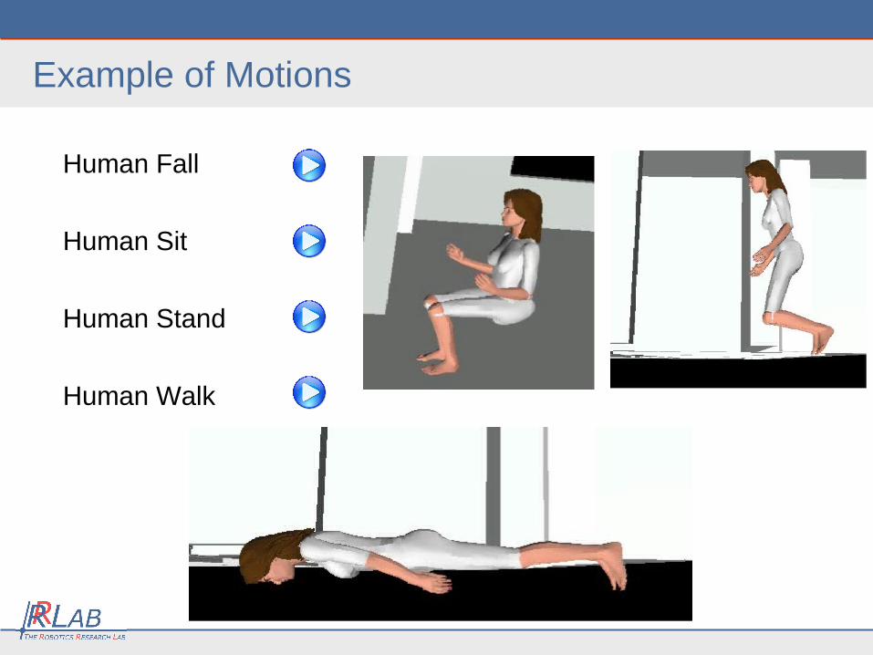
Human Fall
Human Sit
Human Stand
Human Walk
Example of Motions
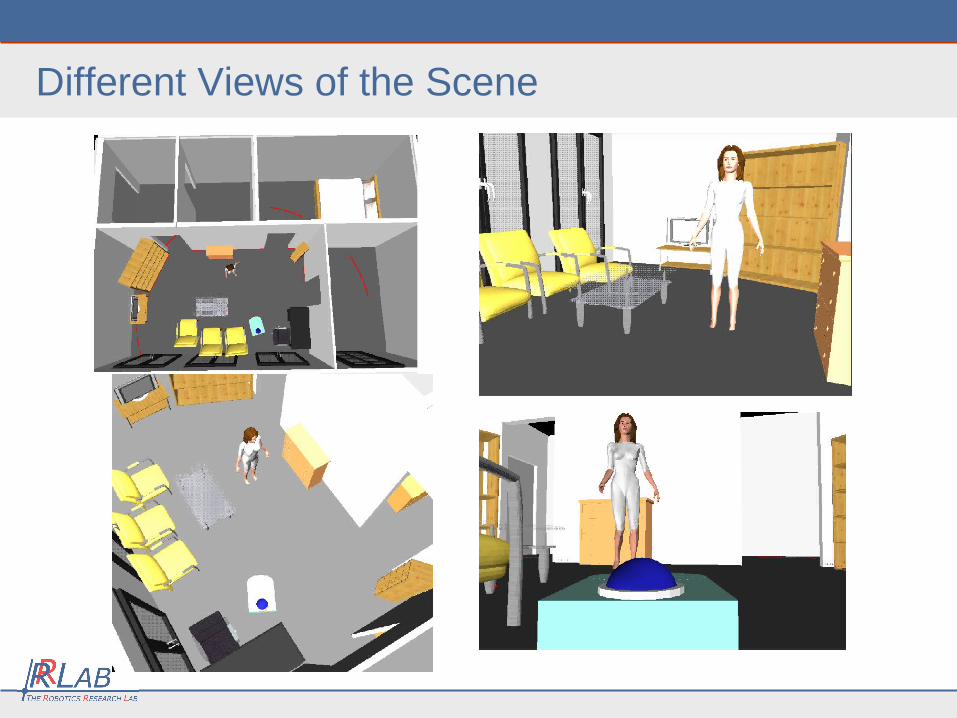
Different Views of the Scene
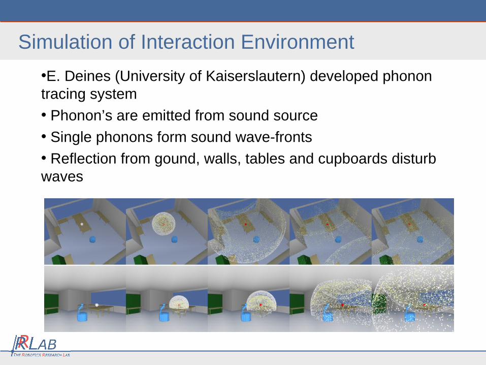
Simulation of Interaction Environment
•E. Deines (University of Kaiserslautern) developed phonon tracing system
• Phonon’s are emitted from sound source
• Single phonons form sound wave-fronts
• Reflection from gound, walls, tables and cupboards disturb waves
Human-Robot Interaction
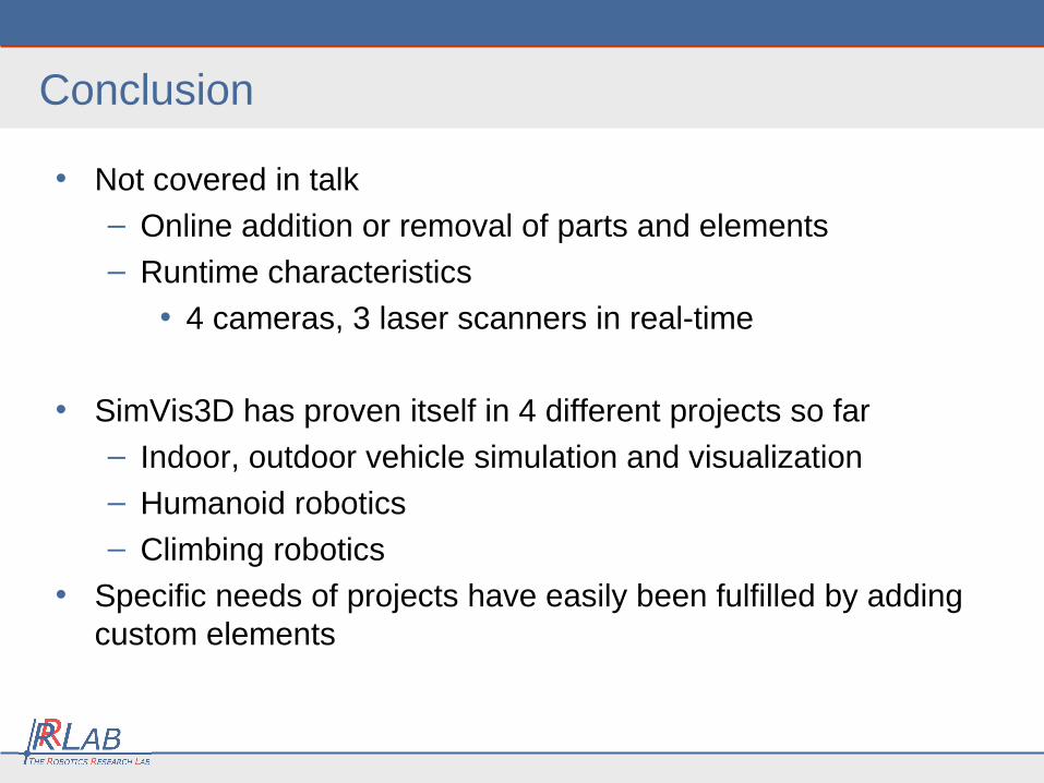
Conclusion
• Not covered in talk
– Online addition or removal of parts and elements
– Runtime characteristics
• 4 cameras, 3 laser scanners in real-time
• SimVis3D has proven itself in 4 different projects so far
– Indoor, outdoor vehicle simulation and visualization
– Humanoid robotics
– Climbing robotics
• Specific needs of projects have easily been fulfilled by adding custom elements
Thanks!