Embed Size (px)
Citation preview
International Research Journal of Engineering and Technology (IRJET) e-ISSN: 2395-0056
Volume: 06 Issue: 05 | May 2019 www.irjet.net p-ISSN: 2395-0072
© 2019, IRJET | Impact Factor value: 7.211 | ISO 9001:2008 Certified Journal | Page 2021
Simulation and Kinematic Analysis of MTAB ARISTO Robot
A Krishna kumar 1, G Suresh2
1PG student & [email protected] 2Associate professor
Dept. of Mechanical Engineering, Vignan's Foundation for Science, Technology & Research, Andhra Pradesh, India ---------------------------------------------------------------------***---------------------------------------------------------------------Abstract –The Grippers of the manipulator are desired to move in a required fashion to do a specific task. The execution of particular task requires the manipulator to follow a preplanned path, which is the larger problem of motion or trajectory planning and motion control for the manipulator. The theme of trajectory planning is to describe the requisite motion of the manipulator as a time sequence of joints/links/end-effectors locations and derivatives of locations, in our manuscript we aim to design MTAB ARISTO robot which suits perfectly for welding applications for a curved profiles, where forward kinematics, inverse kinematics are calculated and simulation of end effector is done for given joint and link parameters and final workspace of manipulator is identified and graphs related to motion of manipulator as a time sequence of joints, links are achieved using roboanalyzer software Key Words: Grippers, trajectory, robo-analyzer, forward kinematics, manipulator
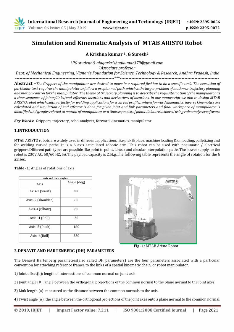
1.INTRODUCTION MTAB ARISTO robots are widely used in different applications like pick & place, machine loading & unloading, palletizing and for welding curved paths. It is a 6 axis articulated robotic arm. This robot can be used with pneumatic / electrical grippers.Different path types are possible like point to point, Linear and circular interpolation paths.The power supply for the robot is 230V AC, 50/60 HZ, 5A.The payload capacity is 2.5kg.The following table represents the angle of rotation for the 6
axises.
Table -1: Angles of rotations of axis
Fig -1: MTAB Aristo Robot
2.DENAVIT AND HARTENBERG (DH) PARAMETERS
The Denavit Hartenberg parameters(also called DH parameters) are the four parameters associated with a particular convention for attaching reference frames to the links of a spatial kinematic chain, or robot manipulator.
1) Joint offset(b): length of intersections of common normal on joint axis
2) Joint angle (θ): angle between the orthogonal projections of the common normal to the plane normal to the joint axes.
3) Link length (a): measured as the distance between the common normals to the axis.
4) Twist angle (α): the angle between the orthogonal projections of the joint axes onto a plane normal to the common normal.
Axis and their angles
Axis Angle (deg)
Axis-1 (waist) 300
Axis -2 (shoulder) 60
Axis-3 (Elbow) 60
Axis -4 (Roll) 30
Axis -5 (Pitch) 180
Axis -6(Roll) 330
International Research Journal of Engineering and Technology (IRJET) e-ISSN: 2395-0056
Volume: 06 Issue: 05 | May 2019 www.irjet.net p-ISSN: 2395-0072
© 2019, IRJET | Impact Factor value: 7.211 | ISO 9001:2008 Certified Journal | Page 2022
so for the given type of joint i.e. revolute or prismatic one of the DH parameters is variable which is called the joint variable, whereas the other three remaining parameters are constant and are called link parameters.
3.FORWARD AND INVERSE KINEMATICS
Both forward and inverse kinematics are important to robotics. The robot teach-pendant uses direct joint control to place the robot tool at desired poses in space. It is a form of forward kinematics control.When the target for an end-effector tool is specified directly, either by a sensor or as the robot interpolates moves along specified curvilinear paths in space, it requires inverse kinematic solutions to generate the necessary joint values.
D-H parameters provide a simple way of relating joint frames relative to each other, although more than one D-H form proliferate the application methods. The inverse kinematic solutions can be complex depending on the robot structure.
3.1 Forward Kinematics
A manipulator is composed of serial links which are affixed to each other revolute or prismatic joints from the base frame through the end-effector. Calculating the position and orientation of the end-effector in terms of the joint variables is called as forward kinematics. In order to have forward kinematics for a robot mechanism in a systematic manner, one should use a suitable kinematics model. Denavit-Hartenberg method that uses four parameters is the most common method for describing the robot kinematics. These parameters ai-1, α i-1, di and θi are the link length, link twist, link offset and joint angle, respectively.
3.2 Inverse Kinematics
The inverse kinematics problem of the serial manipulators has been studied for many decades. It is needed in the control of manipulators. Solving the in-verse kinematics is computationally expansive and generally takes a very long time in the real time control of manipulators. Tasks to be performed by a manipulator are in the Cartesian space, whereas actuators work in joint space. Cartesian space includes orientation matrix and position vector. However, joint space is represented by joint angles. The conversion of the position and orientation of a manipulator end-effector from Cartesian space to joint space is called as inverse kinematics problem.
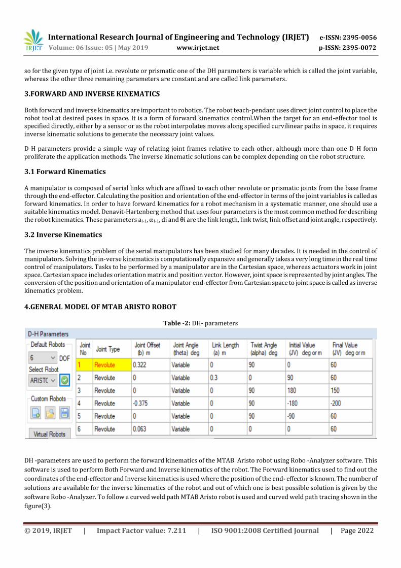
4.GENERAL MODEL OF MTAB ARISTO ROBOT
Table -2: DH- parameters
DH -parameters are used to perform the forward kinematics of the MTAB Aristo robot using Robo -Analyzer software. This
software is used to perform Both Forward and Inverse kinematics of the robot. The Forward kinematics used to find out the
coordinates of the end-effector and Inverse kinematics is used where the position of the end- effector is known. The number of
solutions are available for the inverse kinematics of the robot and out of which one is best possible solution is given by the
software Robo -Analyzer. To follow a curved weld path MTAB Aristo robot is used and curved weld path tracing shown in the
figure(3).
International Research Journal of Engineering and Technology (IRJET) e-ISSN: 2395-0056
Volume: 06 Issue: 05 | May 2019 www.irjet.net p-ISSN: 2395-0072
© 2019, IRJET | Impact Factor value: 7.211 | ISO 9001:2008 Certified Journal | Page 2023
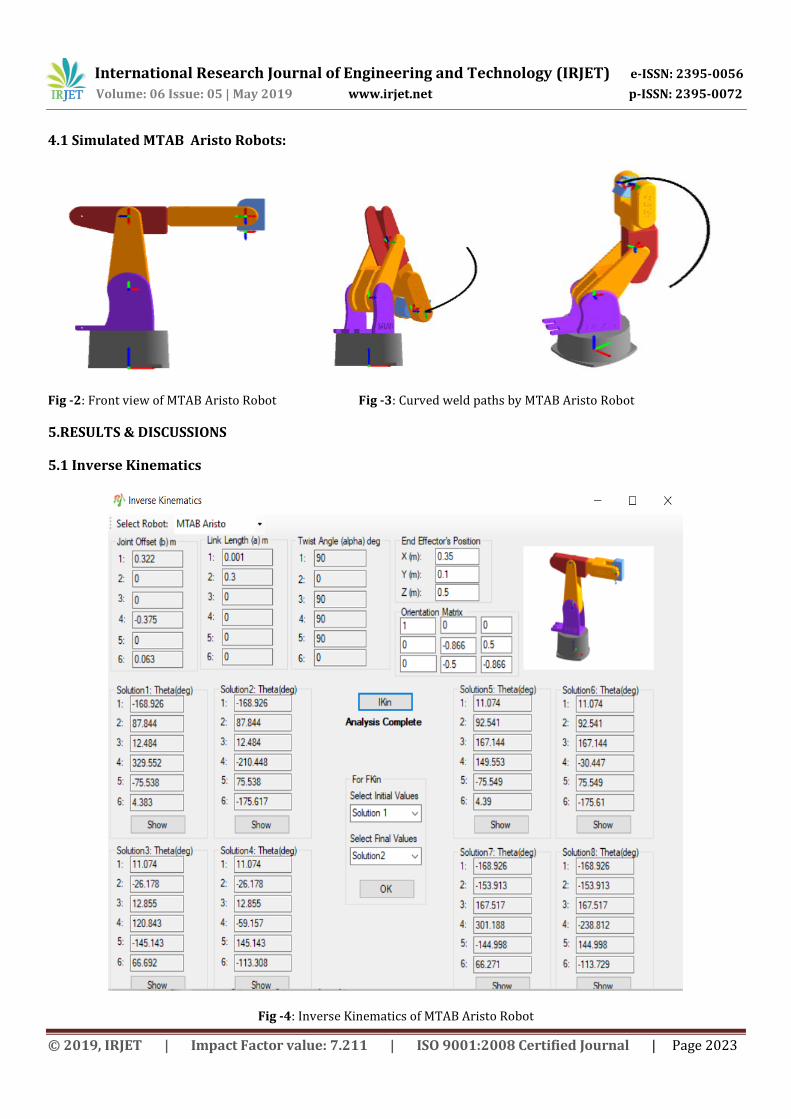
4.1 Simulated MTAB Aristo Robots:
Fig -2: Front view of MTAB Aristo Robot Fig -3: Curved weld paths by MTAB Aristo Robot
5.RESULTS & DISCUSSIONS
5.1 Inverse Kinematics
Fig -4: Inverse Kinematics of MTAB Aristo Robot
International Research Journal of Engineering and Technology (IRJET) e-ISSN: 2395-0056
Volume: 06 Issue: 05 | May 2019 www.irjet.net p-ISSN: 2395-0072
© 2019, IRJET | Impact Factor value: 7.211 | ISO 9001:2008 Certified Journal | Page 2024
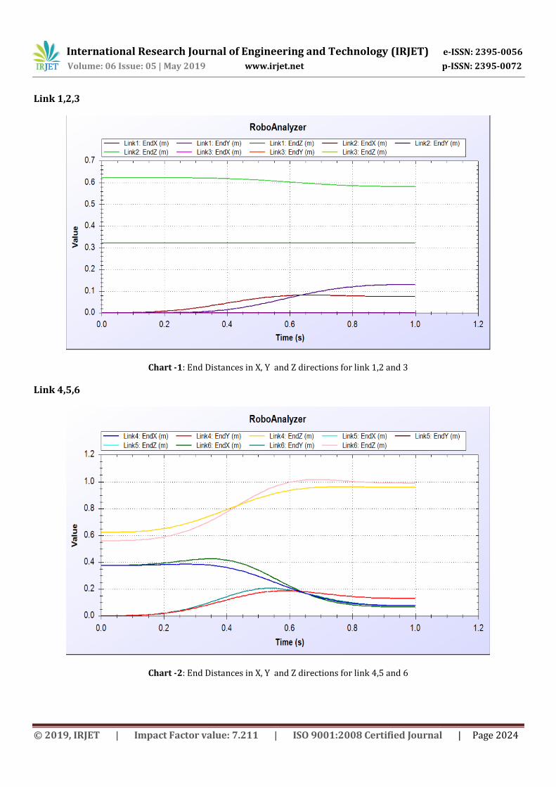
Link 1,2,3
Chart -1: End Distances in X, Y and Z directions for link 1,2 and 3
Link 4,5,6
Chart -2: End Distances in X, Y and Z directions for link 4,5 and 6
International Research Journal of Engineering and Technology (IRJET) e-ISSN: 2395-0056
Volume: 06 Issue: 05 | May 2019 www.irjet.net p-ISSN: 2395-0072
© 2019, IRJET | Impact Factor value: 7.211 | ISO 9001:2008 Certified Journal | Page 2025
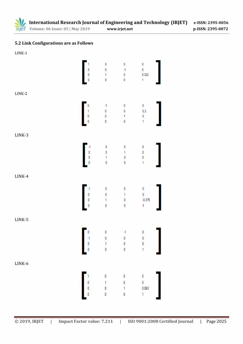
5.2 Link Configurations are as Follows
LINK-1
LINK-2
LINK-3
LINK-4
LINK-5
LINK-6
International Research Journal of Engineering and Technology (IRJET) e-ISSN: 2395-0056
Volume: 06 Issue: 05 | May 2019 www.irjet.net p-ISSN: 2395-0072
© 2019, IRJET | Impact Factor value: 7.211 | ISO 9001:2008 Certified Journal | Page 2026
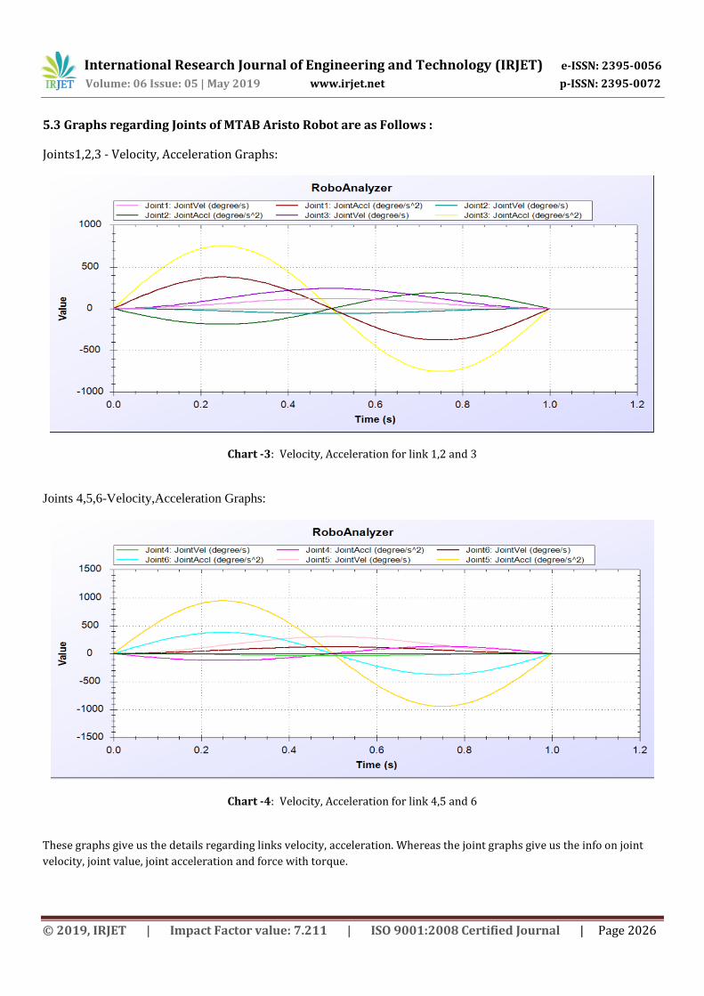
5.3 Graphs regarding Joints of MTAB Aristo Robot are as Follows :
Joints1,2,3 - Velocity, Acceleration Graphs:
Chart -3: Velocity, Acceleration for link 1,2 and 3
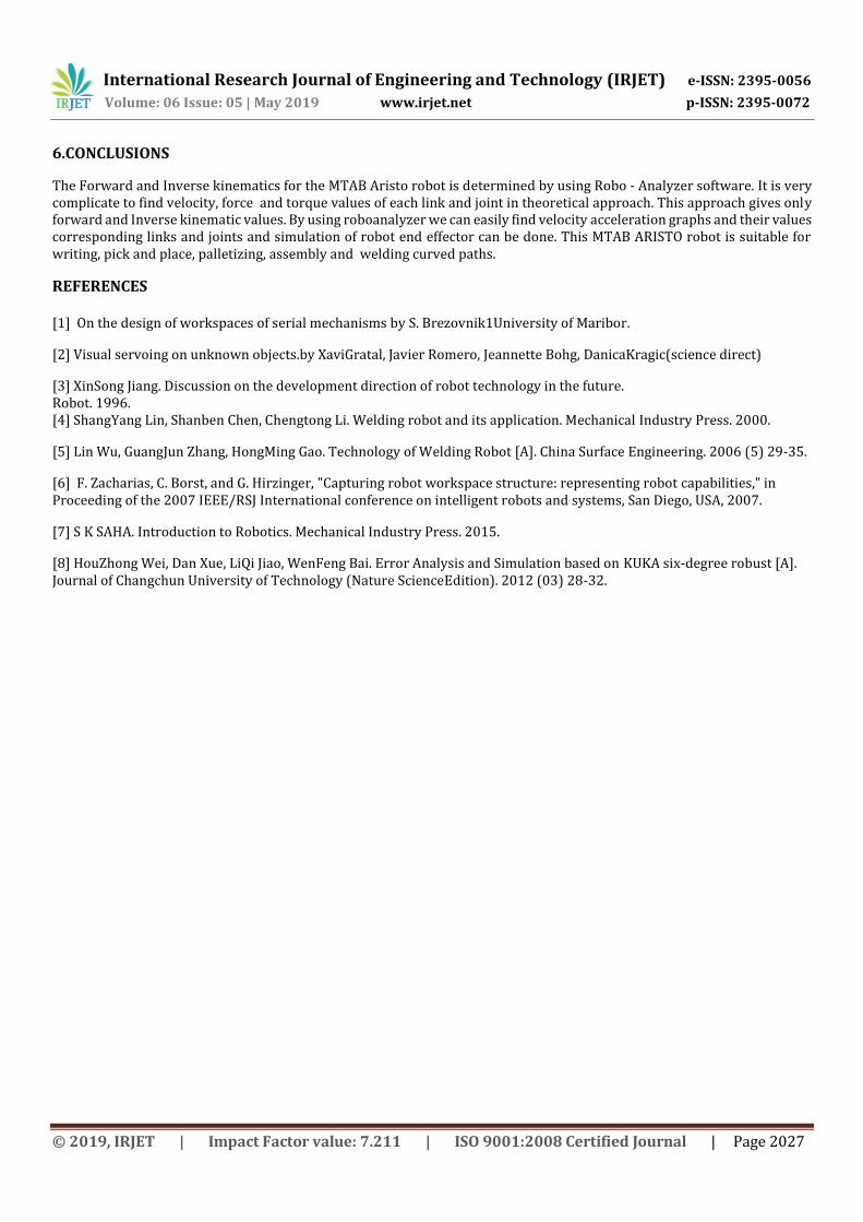
Joints 4,5,6-Velocity,Acceleration Graphs:
Chart -4: Velocity, Acceleration for link 4,5 and 6
These graphs give us the details regarding links velocity, acceleration. Whereas the joint graphs give us the info on joint
velocity, joint value, joint acceleration and force with torque.
International Research Journal of Engineering and Technology (IRJET) e-ISSN: 2395-0056
Volume: 06 Issue: 05 | May 2019 www.irjet.net p-ISSN: 2395-0072
© 2019, IRJET | Impact Factor value: 7.211 | ISO 9001:2008 Certified Journal | Page 2027
6.CONCLUSIONS
The Forward and Inverse kinematics for the MTAB Aristo robot is determined by using Robo - Analyzer software. It is very complicate to find velocity, force and torque values of each link and joint in theoretical approach. This approach gives only forward and Inverse kinematic values. By using roboanalyzer we can easily find velocity acceleration graphs and their values corresponding links and joints and simulation of robot end effector can be done. This MTAB ARISTO robot is suitable for writing, pick and place, palletizing, assembly and welding curved paths.
REFERENCES [1] On the design of workspaces of serial mechanisms by S. Brezovnik1University of Maribor.
[2] Visual servoing on unknown objects.by XaviGratal, Javier Romero, Jeannette Bohg, DanicaKragic(science direct)
[3] XinSong Jiang. Discussion on the development direction of robot technology in the future. Robot. 1996. [4] ShangYang Lin, Shanben Chen, Chengtong Li. Welding robot and its application. Mechanical Industry Press. 2000.
[5] Lin Wu, GuangJun Zhang, HongMing Gao. Technology of Welding Robot [A]. China Surface Engineering. 2006 (5) 29-35.
[6] F. Zacharias, C. Borst, and G. Hirzinger, "Capturing robot workspace structure: representing robot capabilities," in Proceeding of the 2007 IEEE/RSJ International conference on intelligent robots and systems, San Diego, USA, 2007.
[7] S K SAHA. Introduction to Robotics. Mechanical Industry Press. 2015.
[8] HouZhong Wei, Dan Xue, LiQi Jiao, WenFeng Bai. Error Analysis and Simulation based on KUKA six-degree robust [A]. Journal of Changchun University of Technology (Nature ScienceEdition). 2012 (03) 28-32.
![Virtual Robot Simulation in RoboAnalyzer · [2], RoboAnalyzer as robotics teaching and learning software was introduced with many features typically required in a first-level course](https://img.pdfslide.us/doc/110x75/5e21813f7e5d0c252f062375/virtual-robot-simulation-in-2-roboanalyzer-as-robotics-teaching-and-learning.jpg)