Embed Size (px)
Citation preview

Simulation analysis of helical gears in the gear box of the rolling mill Qian Ma1,a, Yonggang Xu2 and Lixin Gao2
1Beijing Key Laboratory of Advanced Manufacturing Technology,Beijing University of Technology,Beijing 100124,China
Keywords: helical gear, ADAMS, dynamics simulation
Abstract. This paper studies the helical gears in the gear box of cold rolling mill in a steel, using software SolidWorks to make one pair of meshing helical gears a solid model, and import the entity model into ADAMS to creat a virtual prototype model, using IMPACT function to define the contact between gears, based on Hertz elastic collision theory, determine the parameters in the IMPACT function. By loading simulation, The speed characteristic curve of the drive shaft and the gear meshing force curve simulation are obtained, compared with theoretical analysis, the correctness of the simulation is verified.
1. Introduction
With the development of rolling technology, The mill has become more automatic and continuous. The rolling speed of high speed wire rolling mill can be achieved hundreds of meters per second, and bear the load changing. The gear box is an important transmission system, if there is a fault, it will cause an enormous economic loss [1].With the aid of software ADAMS, in the stage of product design, can carry out a complete analysis of the whole system, to obtain the optimal design; In the engineering application stage, aiming at the practical problems arising in the work, can find out the root problem [2]. The virtual prototype of a gearbox in meshing helical gear based on ADAMS, through dynamic simulation analysis, research the gear rotational speed, meshing force and meshing frequency, provide the basis for fault analysis and optimum design of the gear box.
2. To establish the virtual prototype model of helical gear According to table 1,design a three-dimensional modeling by using SolidWorks.
Table 1 model of helical gear parameters Gear The number
of teeth Modulus m/mm
Pressure angle/(°)
Width b/mm
Addendum coefficient
Coefficient of top clearance
Spiral angle/(°)
Big gear 41 25 20 350 1 0.25 14(Left) Small gear 30 25 20 350 1 0.25 14(Right)
The helical gear has been established and import ADAMS to establish the virtual prototype model,edit attributes for each component, set the elastic modulus of each gear and shaft for E=2.10×10^5 Mp, Poisson's ratio is ν=0.29, the density is ρ=7.8×10^(-9) t/mm^3. Add rotation pair on the shaft, add a fixed vice between the gear and shaft, add contact between the gear and the gear, add speed drive on the input shaft, add load torque in the output shaft. The virtual prototype model as shown in figure 1.
Figure.1 The virtual prototype model of helical gear pair
2.1 The selection of virtual prototype model of parameter In order to make the simulation analysis more close to actual work condition, do not use
2nd International Conference on Advances in Mechanical Engineering and Industrial Informatics (AMEII 2016)
© 2016. The authors - Published by Atlantis Press 330

idealized geometric constraint definition of helical gear meshing, but the choice of contact force based on constraint relationship. The contact force between the gear by using Impact function method to calculate, the Impact function can be expressed by the following:
𝐹𝐹 = �0 𝑞𝑞 ≥ 𝑞𝑞0
𝐾𝐾(𝑞𝑞0 − 𝑞𝑞)𝑒𝑒 − 𝐶𝐶 ∙𝑑𝑑𝑞𝑞𝑑𝑑𝑡𝑡∙ 𝑠𝑠𝑠𝑠𝑠𝑠𝑠𝑠(𝑞𝑞, 𝑞𝑞0 − 𝑑𝑑, 1, 𝑞𝑞0, 0) 𝑞𝑞 < 𝑞𝑞0 (1)
the step is a step function, the q0 is the two movement of objects before the distance,the q is the two object contact the actual distance in the process of collision, the (q0 − q) is in contact with the actual deformation in the collision process,when q ≥ q0, the two objects do not contact or just contact, the contact force at this time is 0;When q < q0, in the formation of contact force between two objects, contact force and Contact stiffness coefficient K, deflection(𝑞𝑞0 − 𝑞𝑞), the collision force index e and damping coefficient C have relations[3].
The contact stiffness coefficient K depends on the material and structure in the shape of an object, by the Hertz contact theory [4], an object of the contact stiffness by two contact equivalent cylinder to describe, The helical gear contact stiffness coefficient calculation formula is[5]:
⎩⎪⎪⎨
⎪⎪⎧ 𝐾𝐾 = 4
3𝑅𝑅12𝐸𝐸∗
𝑅𝑅 = 𝑖𝑖𝑑𝑑1 𝑐𝑐𝑐𝑐𝑐𝑐 𝛼𝛼𝑡𝑡 𝑡𝑡𝑡𝑡𝑡𝑡𝛼𝛼𝑡𝑡,
2(1+𝑖𝑖) 𝑐𝑐𝑐𝑐𝑐𝑐𝛽𝛽𝑏𝑏
𝛽𝛽𝑏𝑏 = 𝑎𝑎𝑎𝑎𝑎𝑎 𝑠𝑠𝑎𝑎𝑡𝑡(𝑠𝑠𝑎𝑎𝑡𝑡 𝛽𝛽 𝑎𝑎𝑐𝑐𝑠𝑠 𝛼𝛼𝑡𝑡)1𝐸𝐸∗
= 1−𝜐𝜐12
𝐸𝐸1+ 1−𝜐𝜐22
𝐸𝐸2
(2)
i is transmission ratio,𝑑𝑑1 is pitch diameter of the driving wheel,αt is transverse pressure angle,αt
, is end face engagement angle,𝛽𝛽𝑏𝑏 is base helix angle,𝛽𝛽 is helix angle,𝐸𝐸 is Modulus of elasticity, 𝜐𝜐 is Poisson ratio.The stiffness coefficient is K=1.35×10⁶ calculated by the calculation.According to the empirical data, the calculation speed and convergence, after simulation experiment, the collision force index is e=2.2, damping coefficient is C=50Ns/mm, penetration depth is d=0.1mm.
The gears in the meshing process of rotation, to consider the friction between teeth, the working environment of the gear pair after lubrication, according to mechanical design manual and related simulation experience, the static friction coefficient of the gear is 0.08, the dynamic friction coefficient is 0.05,the static slip velocity is 0.1mm/s, the dynamic slip velocity is 10mm/s.
3. Simulation and analysis of the results Based on virtual prototype model, applying a constant speed drive on the input shaft 6000°/s, in
order to make no mutations exert speed,then use the STEP function (time step function) so that the rotating speed reaches the maximum value in 0.3s, STEP(time,0,0d,0.3,6000d), where time is the time variable, select the type of loading velocity, add the load torque output shaft 260KN∙m,with the direction of the input shaft in the same direction. The simulation time is set to 2s, the number of steps is20000, use Wstiff and SI2 integration scheme can get better simulation results. 3.1 Simulation analysis of gear shaft speed
Figures 2 and 3 respectively for the input shaft and the output shaft speed curve,.In the model of virtual prototype, specified clockwise forward direction, from Figure 3 and Figure 4 can be seen, the direction of rotation of the input shaft is positive, the direction of rotation of the output shaft is negative, the direction of rotation of the gear shaft meet external gear transmission direction relation. In 0~0.3s, the input shaft and the output shaft in a slow acceleration state, the speed curve is relatively small fluctuations, to avoid severe shock and vibration, in 0.3~2s, the gear in a stable state of motion, the input shaft and the output shaft speed fluctuation in a mean near, it can be seen from table 2, the simulation speed of input shaft and the output shaft of the average value are close to the theoretical value of speed, speed error can be ignored.
331
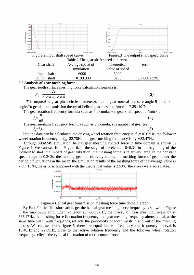
Figure.2 Input shaft speed curve Figure.3 The output shaft speed curve
Table 2 The gear shaft speed and error Gear shaft Average speed of
simulation Theoretical
value of speed error
Input shaft 6000 6000 0 output shaft 8199.999 8200 0.0000122%
3.2 Analysis of gear meshing force The gear tooth surface meshing force calculation formula is:
Fn=2T
d· cos αn· cos β (3)
T is orque,d is gear pitch circle diameter,αn is the gear normal pressure angle,B is helix angle.To get data transmission theory of helical gear meshing force is 7.89×10⁵N.
The gear rotation frequency formula such as 4 formula, n is gear shaft speed(r/min), fr=
n60
(4) The gear meshing frequency formula such as 5 formula, z is number of gear teeth.
fz=frz (5) Into the data can be calculated, the driving wheel rotation frequency is fr1=16.67Hz, the follower
wheel rotation frequency is fr2=22.78Hz, the gear meshing frequency is fz=683.47Hz. Through ADAMS simulation, helical gear meshing contact force in time domain is shown in
Figure 4. We can see from Figure 6, in the stage of accelerated 0~0.3s, in the beginning of the moment to start, the impact of gear vibration, the meshing force is relatively large, in the constant speed stage in 0.3~2s, the running gear is relatively stable, the meshing force of gear under the periodic fluctuations in the mean, the simulation results of the meshing force of the average value is 7.69×10⁵N, the error is compared with the theoretical value is 2.53%, the errors were acceptable.
Figure.4 Helical gear transmission meshing force time domain graph
By Fast Fourier Transformation, get the helical gear meshing force frequency is shown in Figure 5, the maximum amplitude frequency at 683.357Hz, the theory of gear meshing frequency is 683.47Hz, the meshing force fluctuation frequency and gear meshing frequency almost equal, at the same time with multi frequency, reflects the periodicity of tooth mesh in and out of the meshing process.We can see from figure 6, there are equal interval frequency, the frequency interval is 16.48Hz and 22.89Hz, close to the active rotation frequency and the follower wheel rotation frequency, reflects the cyclical fluctuation of tooth contact force.
332

Figure.5 Helical gear transmission
Figure.6 Helical gear transmission meshing meshing frequency diagram local amplification frequency chart
4. Summary The dynamic simulation of the helical gear is carried out by using ADAMS, the gear speed and
meshing force were obtained with the theoretical value, the correctness of the established model is verified, it is revealed that the periodicity of the contact force fluctuation during the meshing process of the helical gears, provide the basis for the optimization design of the gear box.
References
[1]. Lingli Cui, Jianyu Zhang, Lixin Gao.CNT comprehensive diagnosis of typical faults of gear box in high speed wire mill.Journal of Beijing University of Technology.Vol.3 (2007)No.33,p.245-250.
[2]. Wenhua Chen, Qingchuan He,Danwen Zhang.ADAMS2007 Examples of institutional design and analysis.Mechancial Industry Press,2009.
[3]. Yuhua Zhang, Kai Chen, Xiaodong Liu.The revolution of two gear dynamic simulation analysis based on ADAMS.Mechanical transmission. Vol.1 (2015)No.39,p.111-113.
[4]. K.L.Johnson. Contact Mechanics. Cambridge University Press,1985.
[5]. Aimin Liu,Yanzhao Han, Lihong Wang.Finite element analysis on contact stress of tooth surface of helical gear transmission meshing process.Mechanical design and research. Vol.3 (2013)No.29,p.35-38.
333