Embed Size (px)
Citation preview
Simulating Structural Composite Hybrid Parts made from Continuous Fiber Reinforced Thermoplastics
Vasant Pednekar,
SPE ACCE, Sept. 11-13, 2012

2
HiAnt® Simulation
SPE Automotive Composites Conference & ExhibitionSeptember 11-13, 2012
Agenda
Overview
to Lanxess Corporation and High Performance Materials
Introduction: Plastic-Metal
Hybrid Technology
Continuous
Glass Fiber Composite
Hybrid Technology
Mechanical
and Process
simulation
for
composite
sheets
Integrative simulation
of hybrid composite
parts
Validation: Testing
and Simulation
Conclusion

3
HiAnt® Simulation
SPE Automotive Composites Conference & ExhibitionSeptember 11-13, 2012
LANXESS is one of Germany’s most important providers of polymers and chemicals
Employees worldwide
Global orientation
approx. 16,500
48 production sites worldwide
Performance PolymersAdvanced Intermediates Performance Chemicals
Portfolio
Sales in the year 2010 EUR 7.120 bn
Sales in the year 2011 EUR 8.775 bn
Facts & Figures
4
HiAnt® Simulation
SPE Automotive Composites Conference & ExhibitionSeptember 11-13, 2012
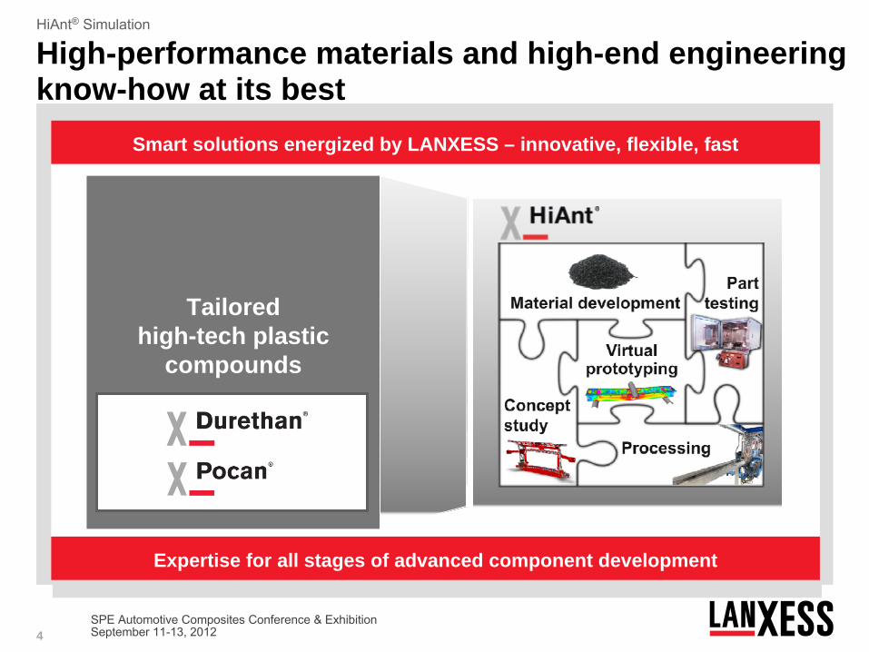
High-performance materials and high-end engineering know-how at its best
Expertise for all stages of advanced component development
Tailored high-tech plastic
compounds
Smart solutions energized by LANXESS – innovative, flexible, fast

5
HiAnt® Simulation
SPE Automotive Composites Conference & ExhibitionSeptember 11-13, 2012
Plastic-Metal Hybrid Technology

6
HiAnt® Simulation
SPE Automotive Composites Conference & ExhibitionSeptember 11-13, 2012
Plastic-Metal hybrid technology Plastic provides full performance
Lightweight structures
(thin wall thickness)
preference for denting
or buckling
The structure can be supported with small
forces, that are carried by the plastic ribs
F1 F2→ →
Fplastic Fplastic→ →
F2 >> F1→ →
sheet
metal
support

7
HiAnt® Simulation
SPE Automotive Composites Conference & ExhibitionSeptember 11-13, 2012
Plastic-Metal hybrid technology The best from two worlds
Metal•
high strength and stiffness
•
ductile behavior•
low CLTE•
Good deep drawing
Hybrid
•
reduced tendency to buckling of thin wall metal structures
•
high energy absorption•
low part weight by thin walls•
high integration of functional elements
•
high precision in production and use
•
high temperature resistance (e-coating capability)
•
design freedom•
good impact strength and stiffness
•
low viscosity•
low density•
resistance against oil, grease and detergent
Polyamide 6 GF

8
HiAnt® Simulation
SPE Automotive Composites Conference & ExhibitionSeptember 11-13, 2012
Plastic-Metal hybrid technology How hybrid is designed
Rib Pattern
Overmolded Edge
Connecting Spots
9
HiAnt® Simulation
SPE Automotive Composites Conference & ExhibitionSeptember 11-13, 2012
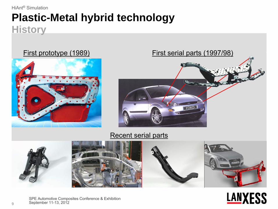
Plastic-Metal hybrid technology History
First prototype
(1989) First serial
parts
(1997/98)
Recent
serial
parts

10
HiAnt® Simulation
SPE Automotive Composites Conference & ExhibitionSeptember 11-13, 2012
More than 50 Mio. produced hybrid-frontends.More than 70 different series applications in automotive.
Plastic-Metal hybrid technology History
11
HiAnt® Simulation
SPE Automotive Composites Conference & ExhibitionSeptember 11-13, 2012
HiAnt® Technology: Continuous Glass Fiber Composite Hybrid Technology
12
HiAnt® Simulation
SPE Automotive Composites Conference & ExhibitionSeptember 11-13, 2012
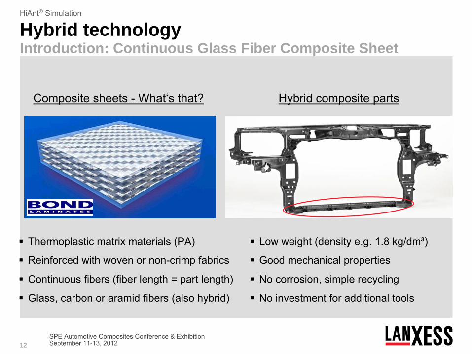
Hybrid technology Introduction: Continuous Glass Fiber Composite Sheet
Hybrid composite
parts
Low weight
(density
e.g. 1.8 kg/dm³)
Good mechanical
properties
No corrosion, simple recycling
No investment
for
additional tools
Composite
sheets
-
What‘s
that?
Thermoplastic
matrix
materials
(PA)
Reinforced
with
woven
or
non-crimp
fabrics
Continuous
fibers
(fiber length
= part
length)
Glass, carbon
or
aramid
fibers
(also hybrid)
13
HiAnt® Simulation
SPE Automotive Composites Conference & ExhibitionSeptember 11-13, 2012
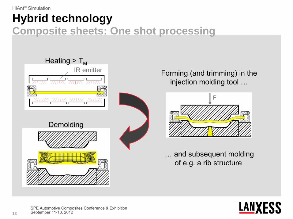
Hybrid technology Composite sheets: One shot processing
Demolding
IR emitterHeating
> TM
Forming
(and trimming) in theinjection
molding
tool
…
… and subsequent
moldingof e.g. a rib
structure

14
HiAnt® Simulation
SPE Automotive Composites Conference & ExhibitionSeptember 11-13, 2012
Hybrid technology Examples made by one shot processing
Door
impact
beam(demonstrator)
Steering-column
holder(demonstrator)
Tepex® + Durethan®
BMBF project
„SpriForm“
in cooperation
withBond Laminates, Audi, KraussMaffei, Jacob Composite, IVW
Tepex® + Durethan®
Projekt in cooperation
withBond Laminates, Engel, LKT, NMF, Siebenwurst
15
HiAnt® Simulation
SPE Automotive Composites Conference & ExhibitionSeptember 11-13, 2012
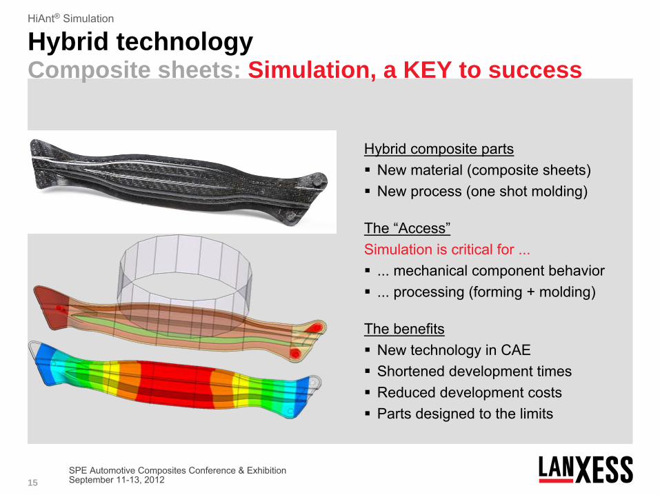
Hybrid technology Composite sheets: Simulation, a KEY to success
Hybrid composite parts New material (composite sheets) New process (one shot molding)
The “Access”Simulation is critical for ... ... mechanical component behavior ... processing (forming + molding)
The benefits New technology in CAE Shortened development times Reduced development costs Parts designed to the limits

16
HiAnt® Simulation
SPE Automotive Composites Conference & ExhibitionSeptember 11-13, 2012
Main mechanical
characteristics
Anisotropy
Non-linearity
Strain
rate dependency
Difference
tension
/ bending
Difference
tension
/ compression
Damage
/ Failure
/ Breakage
Rotation of fiber directions
/
Non-orthogonal
fiber directions
Temperature
dependency
Moisture dependency
Tensile
tests
in different directions
Tepex®
dynalite
102-RG600(x)/45%
Strain [%]
Stre
ss [M
Pa]
0 °7,5 °15 °22,5 °30 °37,5 °45 °
Hybrid technology Composite sheets: Simulation, a Challenge

17
HiAnt® Simulation
SPE Automotive Composites Conference & ExhibitionSeptember 11-13, 2012
Hybrid technology Composite sheets: Simulation, a Challenge
Challenge:No suitable
material modelthat
covers
all relevantmechanical
characteristicsavailable
in commercialsimulation
codes
Solution:Development
of a newmaterial model
forcomposite
sheets
andimplementation
into
acommercial
simulation
code
Main mechanical
characteristics
Anisotropy
Non-linearity
Strain
rate dependency
Difference
tension
/ bending
Difference
tension
/ compression
Damage
/ Failure
/ Breakage
Rotation of fiber directions
/
Non-orthogonal
fiber directions
Temperature
dependency
Moisture dependency

18
HiAnt® Simulation
SPE Automotive Composites Conference & ExhibitionSeptember 11-13, 2012
Hybrid technology Validation of the material model
Tensile
tests
0° Tensile
tests
45°
Tepex®
dynalite
102-RG600(x)/45%
Strain [%]
Stre
ss [M
Pa]
M qsM 1 1/sM 10 1/sM 100 1/sS qsS 1 1/sS 10 1/sS 100 1/s
Strain [%]
Stre
ss [M
Pa]
M qsM 1 1/sM 10 1/sM 100 1/sS qsS 1 1/sS 10 1/sS 100 1/s
19
HiAnt® Simulation
SPE Automotive Composites Conference & ExhibitionSeptember 11-13, 2012
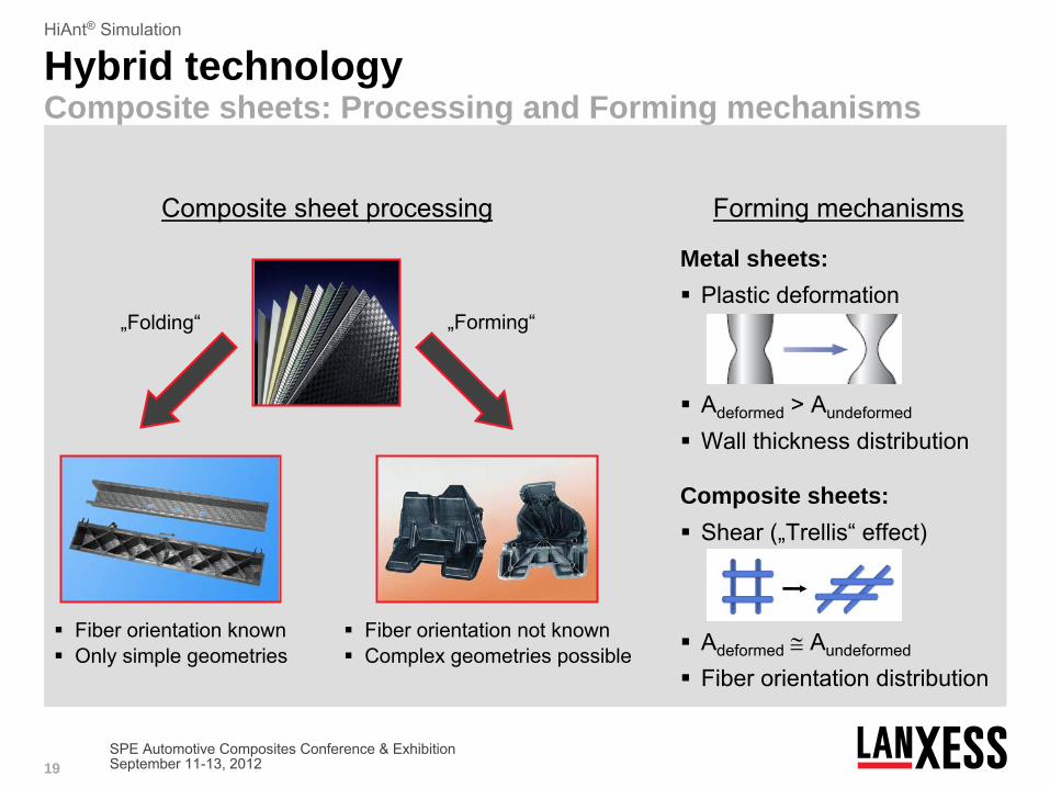
Hybrid technology Composite sheets: Processing and Forming mechanisms
Composite
sheet
processing
Fiber orientation
known Only
simple geometries
„Folding“
Fiber orientation
not
known Complex
geometries
possible
„Forming“
Forming
mechanisms
Metal sheets: Plastic
deformation
Adeformed
> Aundeformed
Wall thickness
distribution
Composite sheets: Shear
(„Trellis“
effect)
Adeformed
Aundeformed
Fiber orientation
distribution

20
HiAnt® Simulation
SPE Automotive Composites Conference & ExhibitionSeptember 11-13, 2012
Forming / Draping Simulation: Material testing - Picture frame test for Forming test
Test setup
and simulation
model
F→
Measurement
results
TM
222 °C
Tepex®
dynalite
102-RG600(x)/45%Measurement
implemented
at LKT, Friedrich-Alexander-Universität Erlangen-Nürnberg
Shear angle [°]Fo
rce
[N] 210 °C
216 °C218 °C220 °C222 °C

21
HiAnt® Simulation
SPE Automotive Composites Conference & ExhibitionSeptember 11-13, 2012
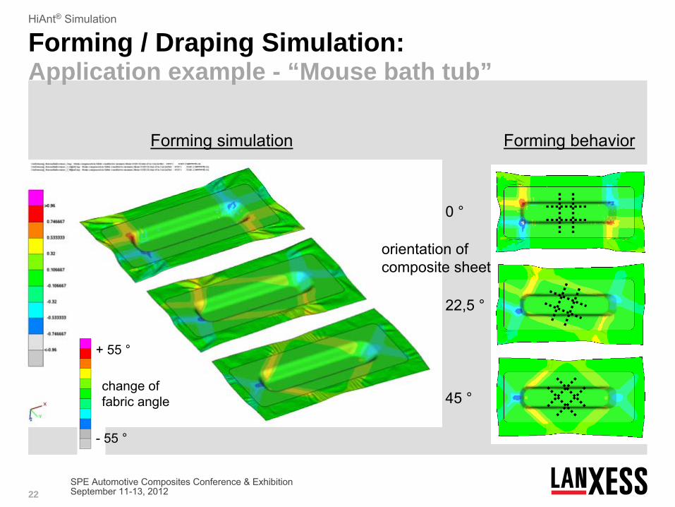
Forming / Draping Simulation: Application example - “Mouse bath tub”
0 °
22,5 °
45 °
+ 55 °
- 55 °
Forming
simulation Forming
behavior
orientation
ofcomposite
sheet
change
offabric
angle
22
HiAnt® Simulation
SPE Automotive Composites Conference & ExhibitionSeptember 11-13, 2012
Forming / Draping Simulation: Application example - “Mouse bath tub”
0 °
22,5 °
45 °
+ 55 °
- 55 °
Forming
simulation Forming
behavior
orientation
ofcomposite
sheet
change
offabric
angle

23
HiAnt® Simulation
SPE Automotive Composites Conference & ExhibitionSeptember 11-13, 2012
Composite Sheet Simulation: Process to simulate Forming for Composite Sheets
Formingproperties
Formingsimulation
Fiberorientation
Mapping
Material modelcomposite
sheet
Mechanicalproperties
HiAnt® material data
HiAnt® simulation

24
HiAnt® Simulation
SPE Automotive Composites Conference & ExhibitionSeptember 11-13, 2012
Short Fiber Composite Simulation: Fiber orientation distribution in injection molded parts
Skin layer: random
orientation
Shear
layer: ll
to flow
direction
Core
layer: to flow
direction(with
fountain
flow)
Orientation due to melt flow Result: Anisotropic
layer
structure
V
V
The fibre orientation is different over the part and in thickness direction !
Injection

25
HiAnt® Simulation
SPE Automotive Composites Conference & ExhibitionSeptember 11-13, 2012
Composite Sheet Simulation: Process to set up simulation for structural part
Formingproperties
Formingsimulation
Fiberorientation
Mapping
Material modelcomposite
sheet
Mechanicalproperties
Moldingproperties
Moldingsimulation
Fiberorientation
Mapping
Material modelDurethan®
Mechanicalproperties
HiAnt® material data
HiAnt® simulation

26
HiAnt® Simulation
SPE Automotive Composites Conference & ExhibitionSeptember 11-13, 2012
Composite Sheet Simulation: Verifying Bond strength of hybrid composite structures
T-joint
plate
(overmolded
composite
sheet) Testing
of bond
strength
Heating
of the
composite
sheet Injection
molding
parameters Flow
length Material …
Effects
on bond
strength
27
HiAnt® Simulation
SPE Automotive Composites Conference & ExhibitionSeptember 11-13, 2012
HiAnt® Simulation: Simulating structural composite hybrid parts
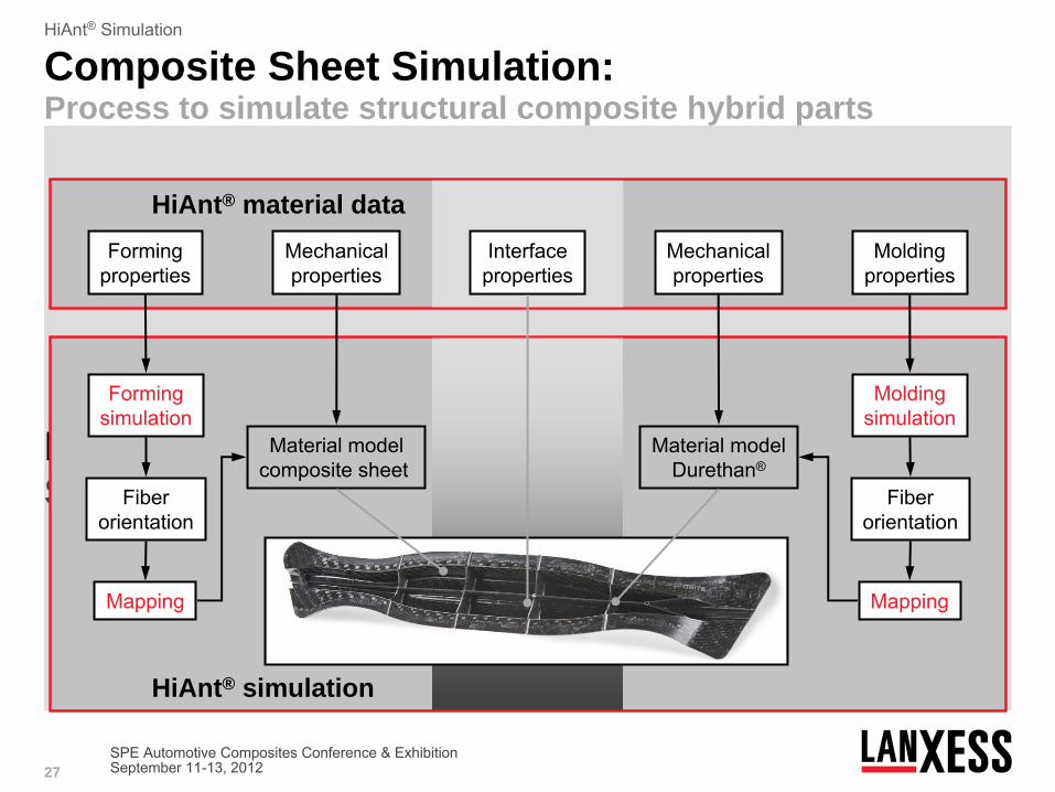
Formingproperties
Formingsimulation
Fiberorientation
Mapping
Material modelcomposite
sheet
Mechanicalproperties
Moldingproperties
Moldingsimulation
Fiberorientation
Mapping
Material modelDurethan®
Mechanicalproperties
Interfaceproperties
Composite Sheet Simulation: Process to simulate structural composite hybrid parts
HiAnt® material data
HiAnt® simulation

28
HiAnt® Simulation
SPE Automotive Composites Conference & ExhibitionSeptember 11-13, 2012
Hybrid technology Validation: Door impact beam (demonstrator)
a
b
cc
b
a Displacement [mm]
Forc
e [k
N]
Measurement Simulation

29
HiAnt® Simulation
SPE Automotive Composites Conference & ExhibitionSeptember 11-13, 2012
Hybrid technology Validation: Bumper beam (demonstrator)
Failure
in the
composite
sheet
mDolly
mPendulum
v0
Tepex® + Durethan®
BMBF project
„SpriForm“
Time [ms]Fo
rce
[kN
]
Measurement Simulation

30
HiAnt® Simulation
SPE Automotive Composites Conference & ExhibitionSeptember 11-13, 2012
Hybrid technology Validation: Upper beam of a frontend (prototype)
Two
different Lanxess rib
materials: Durethan
BKV30 H2.0 901510 Durethan
DP BKV60 H2.0 EF 900116
Part testing
setup
DurethanBKV30
DurethanBKV60 EF
Tepex® + Durethan®
Project in cooperation
with
Faurecia
Displacement [mm]
Forc
e [N
]
Measurement Simulation

31
HiAnt® Simulation
SPE Automotive Composites Conference & ExhibitionSeptember 11-13, 2012
Summary
Plastic-metal-hybrid technology has proven its capabilities for more than 10 years in many different applications
The combination of CFTs
and injection molding leads to hybrid parts with an excellent strength and stiffness. Additionally –
or as an alternative -
lightweight design can be archived and functions can be integrated
The know-how to simulate the material behavior of CFT and their overmolding is crucial for a successful product development

Dr.-Ing. Marcel BrandtCAE Development
/ Part Testing
LANXESS Deutschland GmbH
SCP-GPAD Customer
Engineering Services
41539 Dormagen, Bldg. F45
Phone: +49 2133 / 51 -
29664
Fax: +49 2133 / 51 -
29671
Mobile: +49 175 / 31 -
29664
E-Mail: [email protected]
Internet:
http://www.lanxess.com
Thank You for Your Attention
Vasant PednekarLANXESS Corporation
111, RIDC Parkwest Dr,
Pittsburgh, PA - 15275
Tel.: +1 412 8093557
Mobil: +1 412 5085142
Fax: +1 412 8091067
E-Mail: [email protected]
Internet : http://www.lanxess.com

33
HiAnt® Simulation
SPE Automotive Composites Conference & ExhibitionSeptember 11-13, 2012

34
HiAnt® Simulation
SPE Automotive Composites Conference & ExhibitionSeptember 11-13, 2012
Safe harbour statement
This presentation contains certain forward-looking statements, including assumptions, opinions and views of the company or cited from third party sources. Various known and unknown risks, uncertainties and other factors could cause the actual results, financial position, development or performance of the company to differ materially from the estimations expressed or implied herein. The company does not guarantee that the assumptions underlying such forward looking statements are free from errors nor do they
accept any responsibility for the future accuracy of the opinions expressed
in this presentation or the actual occurrence of the forecasted developments.
No representation or warranty (express or implied) is made as to, and no reliance should be placed on, any information, including projections, estimates, targets and opinions, contained herein, and no liability whatsoever is accepted as to any errors, omissions or misstatements contained herein, and, accordingly, none of the company or any of its parent or subsidiary undertakings or any of such person’s officers, directors or employees accepts any liability whatsoever arising directly or indirectly from the
use of this document.