Embed Size (px)
Citation preview
Computers & Fluids 38 (2009) 843–850
Contents lists available at ScienceDirect
Computers & Fluids
journal homepage: www.elsevier .com/ locate /compfluid
Simulating magnetic positive positioning of cryogenic propellantsin a transient acceleration field
Jeffrey G. Marchetta a,*, Kevin M. Roos b
a Department of Mechanical Engineering, 322D Engineering Sciences Building, University of Memphis, Memphis, TN 38152, United Statesb Department of Mechanical Engineering, 312 Engineering Sciences Building, University of Memphis, Memphis, TN 38152, United States
a r t i c l e i n f o
Article history:Received 22 August 2007Received in revised form 30 June 2008Accepted 11 September 2008Available online 25 September 2008
0045-7930/$ - see front matter � 2008 Elsevier Ltd. Adoi:10.1016/j.compfluid.2008.09.005
* Corresponding author. Tel.: +1 9016783268; fax:E-mail address: [email protected] (J.G. Marc
a b s t r a c t
A computational simulation of magnetic positive positioning (MP2) is developed to model cryogenic pro-pellant reorientation in reduced gravity. Previous efforts have successfully incorporated an electromag-netic field model into an axisymmetric, two-dimensional, incompressible fluid flow model yieldingaccurate predictions of fluid motion induced by a magnetic field. To simulate MP2, a three-dimensionalmagnetic field and magnetic force model was developed as a feature of a commercially available fluidflow model which has been well validated. The computational tool was then improved upon to modelmagnetically induced flows in a transient acceleration field. Simulation predictions obtained with theenhanced model are compared to available reduced gravity experiment data. Evidence is presentedand conclusions are drawn that support the continued use of the simulation as viable modeling and pre-dictive tool in the continuing study of MP2.
� 2008 Elsevier Ltd. All rights reserved.
1. Introduction
Analytical [1], experimental [2], and computational [3] studieshave been performed in order to seek reliable and efficient technol-ogies for the management of cryogenic propellants in a reducedgravity environment. Passive and active systems for propellantmanagement have been utilized on small satellites, but are notwithout their disadvantages. Passive systems, such as liquid acqui-sition devices (LADS), rely upon surface tension forces generatedby specific geometries existing inside the tank, such as screens,channels, or vanes in order to supply liquid to the requisite tanklocation [4,5]. However, these systems result in increased weightof the spacecraft. Active systems can reorient propellant throughthe use of external thrusters that maneuver the tank relative tothe location of the liquid [3,6]. Such impulsive methods hold theadvantage over passive systems because the propellant can berepositioned to meet changing mission requirements. Unfortu-nately, this method increases system complexity because of theadditional thrusters, controls, and fuel.
Although both methods are an effective means to manage liquidpropellants in reduced gravity, the viability of using these systemsfor managing cryogenic propellants for long duration missions isuncertain. In addition, the aforementioned disadvantages suggestthat investigations of other, potentially more efficient, methodsfor propellant management are justified. Magnetic positive posi-tioning (MP2) is a potential third candidate for reorientation. MP2
ll rights reserved.
+1 9016785459.hetta).
utilizes a magnetic field and the magnetic susceptibility of theliquid propellant to achieve reorientation in space tanks. Paramag-netic fluids, such as liquid oxygen (LOX), are attracted to regions ofhigh magnetic field strength, while diamagnetic fluids, like liquidhydrogen (LH2), are repelled from regions of high magnetic fieldstrength.
The concept of using magnetic fields to influence the flowof susceptible liquids has been considered for over 40 years [7].For terrestrial applications, the effects of a magnetic field on aparamagnetic fluid are negated by the dominant gravitationalforces. Fundamental hydrodynamic equations for the coupling ofthe magnetic force with other forces that would induce flow of aNewtonian fluid were developed by Neuringer and Rosenweig [8]in 1964. The stabilizing influence of a magnetic force on aRayleigh–Taylor instability was demonstrated by Zelazo andMelcher [9] in 1969. Likewise, Bashtovoy and Krakov [10] showedthat an imposed magnetic field can have a stabilizing influence ona jet of magnetically susceptible fluid. In 1988, Berkovsky andSmirnov [11] explored sessile drop stability and shape in the pres-ence of a magnetic field. Later on, Basaran and Wohlhuter [12]looked into the shape and stability of both pendant and sessiledrops in similar conditions. Finally, Bashtovoy, Berkovsky, andVislovich [13] concluded that the free surface of a magneticallysusceptible fluid will conform to a contour of constant magneticfield intensity in the presence of a magnetic field, and neglectinggravitational and capillary forces.
Early investigations into the plausibility of using electromag-netic fields to manage liquid propellants were dismissed due tothe unacceptable risk of arcing inside the propellant tank due to
Nomenclature
a minor axis of fluid profileb major axis of fluid profileB magnetic inductionC constante unit vectorE energyg acceleration due to gravityh heightH magnetic intensityl characteristic lengthm magnetic dipole strengthM magnetization
n coordinate normal to surfaceq quantity component of energyRMS root mean squares surface directionR, H, U spherical coordinates with H in x–y planeR, h, z cylindrical coordinates with h in x–y planex, y, z cartesian coordinate directionsV volumelo permeability of free spaceq densityr surface tension coefficientvm magnetic susceptibility
844 J.G. Marchetta, K.M. Roos / Computers & Fluids 38 (2009) 843–850
the magnetic field itself [7]. Improvements in high temperaturesuperconducting material formed a new interest in the applicationof magnetic positive positioning. In 1995, The NASA Marshall SpaceFlight Center conducted a series of flight experiments to studymagnetically actuated propellant orientation, or MAPO [14]. Theobjective of the experiments was to investigate the feasibility ofusing a magnetic field to positively reorient liquid propellant with-in a tank while maintaining its position during propellant expul-sion and tank filling operations. The experiments utilizedferrofluids to simulate liquid oxygen, and a video camera was usedto capture liquid motion within a 10 cm diameter transparentcylindrical tank during the reduced gravity phase of the parabolicflight pattern of the NASA KC-135 aircraft. Several difficulties arisefrom the experiment itself. Only 20–30 s of reduced gravity flighttime were available for each experiment, and the flows were influ-enced by unrepeatable initial conditions. Furthermore, the ferrofl-uids used serve only as an approximation for the properties ofliquid oxygen.
A purely experimental approach for evaluating the feasibility ofMP2 would be limited by the ability to collect sufficient data for fullscale tanks and would be greatly hindered by expense and timeconstraints. A computational simulation is an attractive alternativefor assessing the feasibility of magnetic positive positioning ofpropellants for future spacecraft. Hochstein et al. [15] developeda computational simulation of the MAPO experiment using amagnetic dipole to represent the magnetic field, and presentedpre-flight flow field predictions. Marchetta and Hochstein [16,17]integrated the MAPO magnetic field configuration into the simula-tion and assessed the fidelity of the computational model by com-paring flow field predictions to available flight images. Marchettaand Winter [18] incorporated a electromagnetic field model andan incompressible flow model to simulate realistic magnetic fields.
This paper presents results obtained using a three-dimensionalsimulation of MP2. Most of the simulations presented herein of theMAPO experiment show good agreement with the flow behaviorobserved in photographs taken during the flight experiment [14].It is shown that the current three-dimensional model of MP2
exceeds the capabilities of its predecessor in its ability to modelasymmetric as well as fluctuating acceleration environments.Simulation results were reviewed to assess the utility of the newsimulation for future studies and experiment design.
2. Mathematical models
At the temperatures and pressures associated with cryogenicpropellant storage tanks, LOX and LH2 are well characterized asincompressible, constant property, Newtonian fluids. The Navier
Stokes momentum equation, which describes the unsteady flowof such a fluid, is given by
q@ V*
@tþ qðV
*
�rÞV*
¼ �rpþ lr2 V*
þq g*þF*
M: ð1Þ
Neuringer and Rosensweig [7] present a development of themagnetic force per unit volume in mks units:
F*
M ¼ l0ðM*
�rÞH*
: ð2Þ
Assuming the fluid to be nonconducting, the magnetization tobe in the direction of the local magnetic field, and the displacementcurrent to be negligible, the magnetic force per unit volumebecomes
F*
M ¼ l0MrH: ð3Þ
For low intensity magnetic fields associated with permanentmagnets and small electromagnets, and the assumption that themagnetization is temperature independent, the magnetization isdefined as
M ¼ vH ð4Þ
For some liquids, such as a ferrofluid, the magnetic susceptibil-ity is not constant and increases non-linearly with an increase inthe magnetic field strength. The magnetic intensity in mks unitsis given as
H ¼ Bl0ð1þ vÞ : ð5Þ
3. Computational modeling
A computational simulation is used to model unsteady, incom-pressible flows with deforming free surfaces in which surface ten-sion forces are significant was enhanced to simulate MP2 inreduced gravity. The axisymmetric model used by Hochstein,Marchetta et al. [15–20], a variant of the RIPPLE code, has beenextensively validated in modeling free surface flows with surfacetension and the propellant management applications, includingMP2. The commercial software, FLUENT [21], is a state-of-the-artcomputer program for modeling fluid flow and heat transfer in com-plex geometries. Among its many capabilities, FLUENT can modeltransient, three-dimensional, multiphase, incompressible flowsand is well suited for modeling MP2. For all flows, FLUENT solvesconservation equations for mass and momentum sequentially. FLU-ENT uses a control volume-based technique and upwind differenc-ing to convert the governing equations to algebraic equations that
0.0
0.2
0.4
0.6
0.8
1.0
-1 -0.5 0 0.5 1Normalized Radius
Nor
mal
ized
Men
iscu
s H
eigh
t
Analytic
Simulation
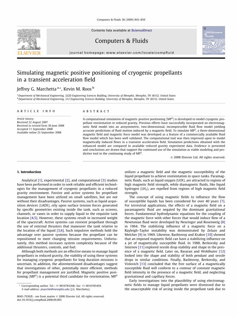
Fig. 1. Normalized, steady-state, and free surface shape for LOX under the influenceof capillary forces.
0.00
0.02
0.04
0.06
0.08
0.10
0.00 0.02 0.04 0.06Distance along z axis, m
Dis
tanc
e al
ong
radi
al a
xis,
m
Analytic
Simulation
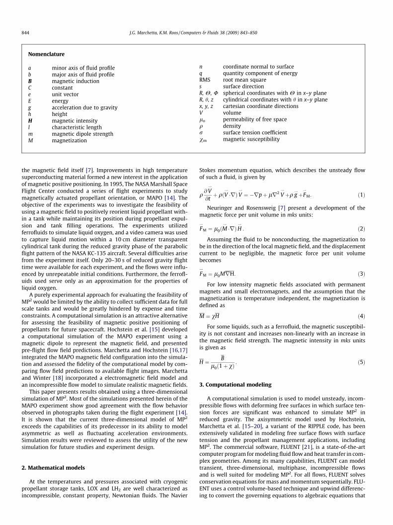
Fig. 2. Steady-state, free surface shape for LOX under the influence of a dipolemagnetic field and a contour of constant H, A/m.
J.G. Marchetta, K.M. Roos / Computers & Fluids 38 (2009) 843–850 845
can be solved numerically. Second order upwind differencing is uti-lized for all FLUENT simulation predictions presented herein. FLU-ENT uses a co-located scheme; whereby pressure and velocity areboth stored at cell centers. Therefore, an interpolation scheme is re-quired to compute the face values of pressure from the cell values.For the following simulations, the body force weighted scheme isutilized to compute the face pressure by assuming that the normalgradient of the difference between pressure and body forces is con-stant. The pressure-implicit with splitting of operators (PISO) pres-sure–velocity coupling scheme is used to obtain a semi-implicitpressure correction equation. The pressure-correction equation issubsequently solved using the algebraic multigrid (AMG) method.Temporal discretization is accomplished using implicit time inte-gration, which is unconditionally stable with respect to time stepsize. Solutions are subsequently iterated at each time level untilthe convergence criteria are met.
The location of multiple phases within the mesh is determinedusing the volume-of-fluid (VOF) function, f. The VOF formulationrelies on the fact that two or more phases are not interpenetrating.The geometric reconstruction scheme is used to reconstruct theinterface between fluids using a piecewise-linear approach. Surfacetension forces are computed using the Continuum Surface ForceModel and a static contact angle can be specified to model walladhesion.
The addition of the magnetic force source term is achievedthrough use of a user defined function [22] (UDF) in FLUENT. Itwas necessary to define a new variable to introduce the magneticfield intensity, H. For the preliminary simulations of the MAPOexperiment, a UDF was written which interpolates measured mag-netic field data on to a computational mesh. In addition, the mag-netic field intensity was utilized to compute the gradient of themagnetic field intensity. Martin and Holt [14] provide tables ofmagnetization measurements, taken from a magnetometer, forthe ferrofluids used in the experiment. Coefficients for a growthsaturation function were sought using regression of magnetizationmeasurements. For the 30:1 mixture, the regression analysis yieldsthe magnetization (A/m) as a function of the magnetic field inten-sity such that
M ¼ 187H13224þ H
ð6Þ
where the numbers 187 and 13,224 are coefficients of the curve-fit.Similarly, for the simulations of the MAPO experiments contain-
ing a 133:1 water/ferro-fluid mixture, the expression for magneti-zation can also be modeled as a growth saturation function. Themagnetization is again a function of magnetic field intensity suchthat
M ¼ 187H13108þ H
ð7Þ
The magnetization for the 10:1 water/ferro-fluid mixture is afunction of magnetic field intensity such that
M ¼ 149H6755þ H
ð8Þ
In order to simulate the MAPO experiment, it was necessary toinclude the transient acceleration fields experienced by the tankson board the KC-135 aircraft. The previous UDF was improvedupon to linearly interpolate accelerometer data taken during theMAPO experiments, and provide the computational tool with theactual transient acceleration environment measured.
4. Model verification and validation
Three benchmark cases were chosen to verify and validate theMP2 model. The first simulation was a cylindrical tank with a ra-
dius of 0.0762 m and a height 0.381 m and was subjected only tocapillary forces. The tank was filled with liquid oxygen, such that40% of tank volume was full. The simulation was initialized witha flat 1 g interface. A small contact angle of 0.1 � was specified toapproximate a 0 � contact angle, at the boundaries, and the surfacetension coefficient was assumed to be constant. For solid wallboundary conditions, the impermeable no-slip condition is im-posed. Three non-uniform hexahedral meshes of increasing meshdensity were simulated and results obtained using a mesh with174,336 cells, produced a mesh independent solution. Fig. 1 illus-trates the simulated and analytic normalized free surface shapefor a plane 2-D cross-section of the cylinder for the first benchmarkcase. It has been shown that an equilibrium zero gravity meniscuswith a 0 � contact angle will conform to a half sphere in a cylindri-cal container, such that the normalized meniscus height is equal tonormalized radius of the cylinder. As shown in Fig. 1, the simulatedzero-gravity meniscus is in good qualitative agreement with theanalytic solution and the RMS error is 0.01.
Another case was devised to determine whether liquid oxygeninside a tank subjected to the dipole magnetic field would conformto a contour of constant magnetic field intensity as predicted bytheory. The dipole model was used to validate the implementationof a UDF in FLUENT, specifically the magnetic force source termmodel. Marchetta [23] shows that a contour of constant magneticfield intensity can be obtained from Eq. (6). To simplify the simu-lation setup, a square box of 0.1 m length was partially filled withLOX. The LOX is initialized a quarter sphere positioned centered inone corner of the box. The computational mesh consisted of 64,000uniform hexahedral cells. The dipole magnet was shifted awayfrom the box at a distance of 0.05 m to avoid having a singularityin the computational domain. A constant dipole strength was spec-ified and the simulation was iterated until an equilibrium free sur-face was achieved. Fig. 2 illustrates the simulation prediction forthe equilibrium free surface shape for LOX under the influence of
846 J.G. Marchetta, K.M. Roos / Computers & Fluids 38 (2009) 843–850
the dipole magnetic field. The RMS error between the predictedfree surface shape and the analytic solution of a contour of con-stant H as predicted by theory was 0.01. It can be concluded thatthe dipole magnetic force model UDF was properly implementedin FLUENT.
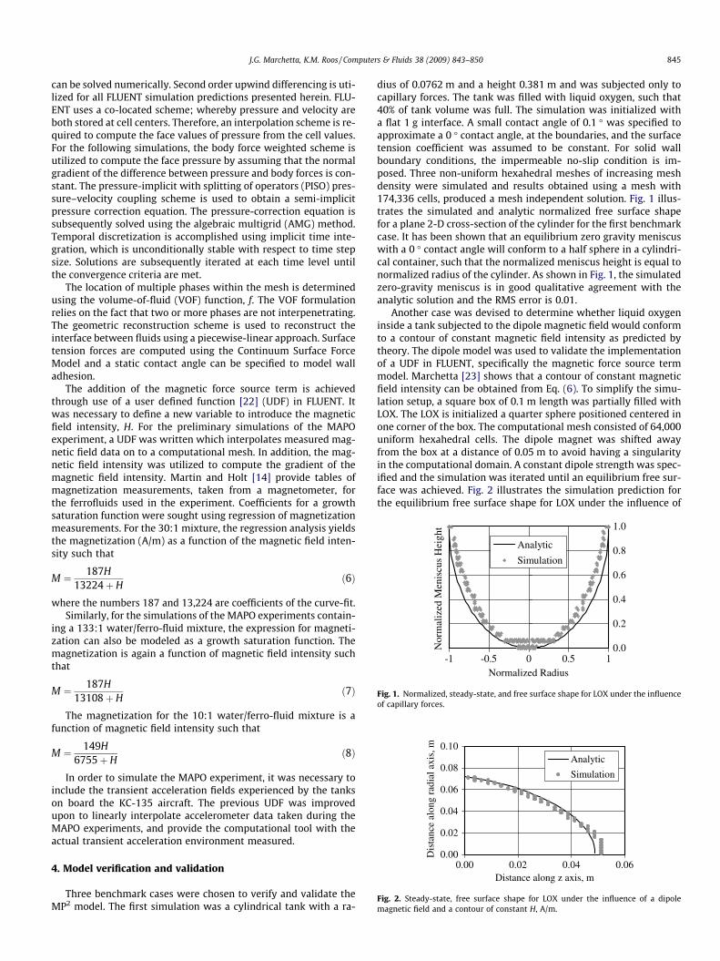
The final benchmark validation case, a cylindrical tank with a10% fill of LOX was subjected to the magnetic force exerted bythe MAPO experiment permanent ring magnet. The rare Earth per-manent magnet has a thickness of 0.0381 m, and inner and outerdiameters of 0.1016 m and 0.254 m, respectively. This case waschosen to validate the implementation of a second FLUENT UDF,which uses the measured magnetic data from the experimentand interpolates the data onto a computational mesh. Again, the-ory states the steady-state interface should conform to a contourof constant magnetic field intensity. The MAPO tank geometry, acylindrical tank with a radius of 0.0762 m and a height 0.254 m,was chosen for this simulation. Noting that a mesh independentflow field was observed in the first benchmark case and the simi-larity in the cylindrical geometry of both cases, an equivalent meshdensity was specified for this study. The surface of the ring magnet,which has a maximum flux of about 0.5 T, is positioned 0.0175 mbelow the tank. Fig. 3 shows the contours of constant magneticfield intensity for a plane 2-D cross-section of the tank. The simu-lated equilibrium free surface shape qualitatively conformed to thecontours of constant H as depicted in Fig. 3. It can be concludedthat the influence of the MAPO ring magnet is properly accountedfor in the 2nd FLUENT UDF.
5. MAPO experiment predictions
The only data available for code validation directly related toMP2 in reduced gravity is the preliminary data from the MAPOexperiment [14]. For the MAPO experiments, the only flow fielddata available is for a 50% tank fill and it is in the form of still-frames extracted from those recordings. It should be noted thatquantitative comparison between computational flow field predic-tions and experiment data is complicated by several factors. First,the ferrofluid/water mixture is very opaque so many of the flow
Fig. 3. Steady-state, free surface shape for a 10% fill of LOX under the influence ofthe MAPO magnetic field and contours of constant H, A/m, inside the tank.
details internal to the tank surface cannot be seen once the liquidhas coated the outer tank wall. Further, the angle of view for therecordings is not normal to the cylinder so problems with datainterpretation due to the refraction of light as it passes throughthe cylindrical wall of the acrylic tank are exacerbated. In additionto those difficulties, there is an important difference between thesimulation and experiment. The computational simulation beginswith a perfectly flat initial interface and instantly changes from anormal 1 g environment to the transient acceleration environment.The experiment initial free surface shape is not precisely mea-sured. Therefore, it is justifiable to assume that some disparity willbe observed between the simulation and experiment due to thevariations in initial free surface conditions, and due to the differ-ences between the abrupt change of the computational simulationacceleration environment and the more gradual change of theexperiment environment. As such, it is only reasonable to drawconclusions which are based on qualitative comparisons of the sur-face shape.
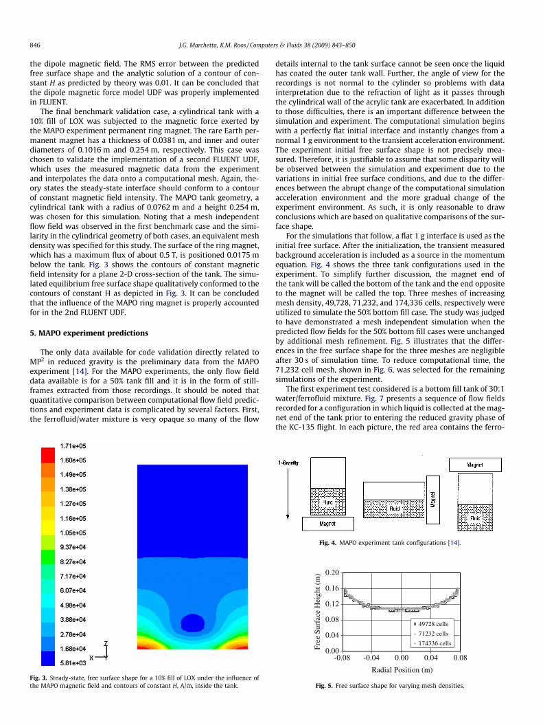
For the simulations that follow, a flat 1 g interface is used as theinitial free surface. After the initialization, the transient measuredbackground acceleration is included as a source in the momentumequation. Fig. 4 shows the three tank configurations used in theexperiment. To simplify further discussion, the magnet end ofthe tank will be called the bottom of the tank and the end oppositeto the magnet will be called the top. Three meshes of increasingmesh density, 49,728, 71,232, and 174,336 cells, respectively wereutilized to simulate the 50% bottom fill case. The study was judgedto have demonstrated a mesh independent simulation when thepredicted flow fields for the 50% bottom fill cases were unchangedby additional mesh refinement. Fig. 5 illustrates that the differ-ences in the free surface shape for the three meshes are negligibleafter 30 s of simulation time. To reduce computational time, the71,232 cell mesh, shown in Fig. 6, was selected for the remainingsimulations of the experiment.
The first experiment test considered is a bottom fill tank of 30:1water/ferrofluid mixture. Fig. 7 presents a sequence of flow fieldsrecorded for a configuration in which liquid is collected at the mag-net end of the tank prior to entering the reduced gravity phase ofthe KC-135 flight. In each picture, the red area contains the ferro-
Fig. 4. MAPO experiment tank configurations [14].
0.00
0.04
0.08
0.12
0.16
0.20
-0.08 -0.04 0.00 0.04 0.08
Radial Position (m)
Fre
e S
urfa
ce H
eigh
t (m
)
49728 cells
71232 cells
174336 cells
Fig. 5. Free surface shape for varying mesh densities.
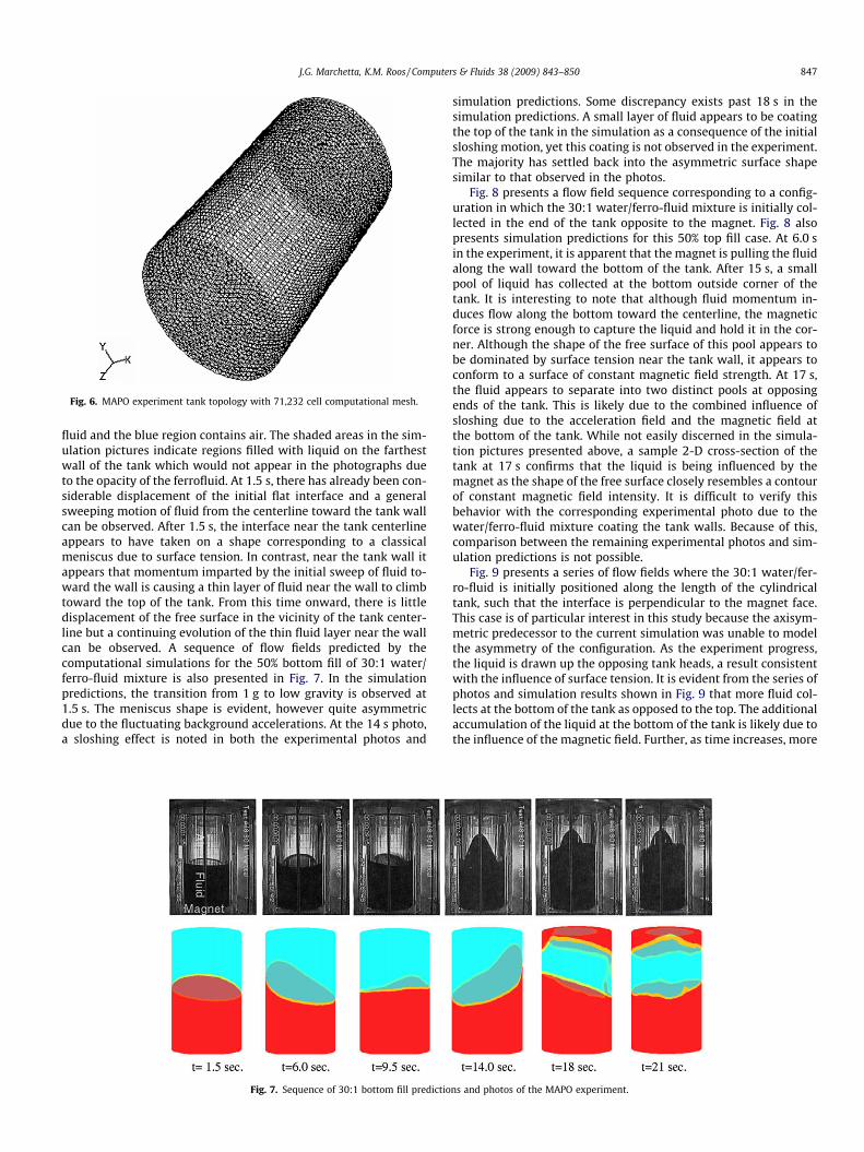
Fig. 6. MAPO experiment tank topology with 71,232 cell computational mesh.
J.G. Marchetta, K.M. Roos / Computers & Fluids 38 (2009) 843–850 847
fluid and the blue region contains air. The shaded areas in the sim-ulation pictures indicate regions filled with liquid on the farthestwall of the tank which would not appear in the photographs dueto the opacity of the ferrofluid. At 1.5 s, there has already been con-siderable displacement of the initial flat interface and a generalsweeping motion of fluid from the centerline toward the tank wallcan be observed. After 1.5 s, the interface near the tank centerlineappears to have taken on a shape corresponding to a classicalmeniscus due to surface tension. In contrast, near the tank wall itappears that momentum imparted by the initial sweep of fluid to-ward the wall is causing a thin layer of fluid near the wall to climbtoward the top of the tank. From this time onward, there is littledisplacement of the free surface in the vicinity of the tank center-line but a continuing evolution of the thin fluid layer near the wallcan be observed. A sequence of flow fields predicted by thecomputational simulations for the 50% bottom fill of 30:1 water/ferro-fluid mixture is also presented in Fig. 7. In the simulationpredictions, the transition from 1 g to low gravity is observed at1.5 s. The meniscus shape is evident, however quite asymmetricdue to the fluctuating background accelerations. At the 14 s photo,a sloshing effect is noted in both the experimental photos and
Fig. 7. Sequence of 30:1 bottom fill predictio
simulation predictions. Some discrepancy exists past 18 s in thesimulation predictions. A small layer of fluid appears to be coatingthe top of the tank in the simulation as a consequence of the initialsloshing motion, yet this coating is not observed in the experiment.The majority has settled back into the asymmetric surface shapesimilar to that observed in the photos.
Fig. 8 presents a flow field sequence corresponding to a config-uration in which the 30:1 water/ferro-fluid mixture is initially col-lected in the end of the tank opposite to the magnet. Fig. 8 alsopresents simulation predictions for this 50% top fill case. At 6.0 sin the experiment, it is apparent that the magnet is pulling the fluidalong the wall toward the bottom of the tank. After 15 s, a smallpool of liquid has collected at the bottom outside corner of thetank. It is interesting to note that although fluid momentum in-duces flow along the bottom toward the centerline, the magneticforce is strong enough to capture the liquid and hold it in the cor-ner. Although the shape of the free surface of this pool appears tobe dominated by surface tension near the tank wall, it appears toconform to a surface of constant magnetic field strength. At 17 s,the fluid appears to separate into two distinct pools at opposingends of the tank. This is likely due to the combined influence ofsloshing due to the acceleration field and the magnetic field atthe bottom of the tank. While not easily discerned in the simula-tion pictures presented above, a sample 2-D cross-section of thetank at 17 s confirms that the liquid is being influenced by themagnet as the shape of the free surface closely resembles a contourof constant magnetic field intensity. It is difficult to verify thisbehavior with the corresponding experimental photo due to thewater/ferro-fluid mixture coating the tank walls. Because of this,comparison between the remaining experimental photos and sim-ulation predictions is not possible.
Fig. 9 presents a series of flow fields where the 30:1 water/fer-ro-fluid is initially positioned along the length of the cylindricaltank, such that the interface is perpendicular to the magnet face.This case is of particular interest in this study because the axisym-metric predecessor to the current simulation was unable to modelthe asymmetry of the configuration. As the experiment progress,the liquid is drawn up the opposing tank heads, a result consistentwith the influence of surface tension. It is evident from the series ofphotos and simulation results shown in Fig. 9 that more fluid col-lects at the bottom of the tank as opposed to the top. The additionalaccumulation of the liquid at the bottom of the tank is likely due tothe influence of the magnetic field. Further, as time increases, more
ns and photos of the MAPO experiment.
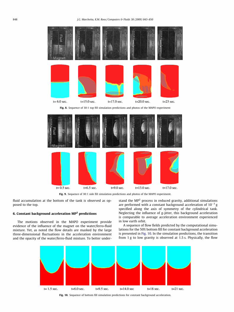
Fig. 8. Sequence of 30:1 top fill simulation predictions and photos of the MAPO experiment
Fig. 9. Sequence of 30:1 side fill simulation predictions and photos of the MAPO experiment.
848 J.G. Marchetta, K.M. Roos / Computers & Fluids 38 (2009) 843–850
fluid accumulation at the bottom of the tank is observed as op-posed to the top.
6. Constant background acceleration MP2 predictions
The motions observed in the MAPO experiment provideevidence of the influence of the magnet on the water/ferro-fluidmixture. Yet, as noted the flow details are masked by the largethree-dimensional fluctuations in the acceleration environmentand the opacity of the water/ferro-fluid mixture. To better under-
Fig. 10. Sequence of bottom fill simulation predi
stand the MP2 process in reduced gravity, additional simulationsare performed with a constant background acceleration of 10�3 gspecified along the axis of symmetry of the cylindrical tank.Neglecting the influence of g-jitter, this background accelerationis comparable to average acceleration environment experiencedin low earth orbit.
A sequence of flow fields predicted by the computational simu-lations for the 50% bottom fill for constant background accelerationis presented in Fig. 10. In the simulation predictions, the transitionfrom 1 g to low gravity is observed at 1.5 s. Physically, the flow
ctions for constant background acceleration.
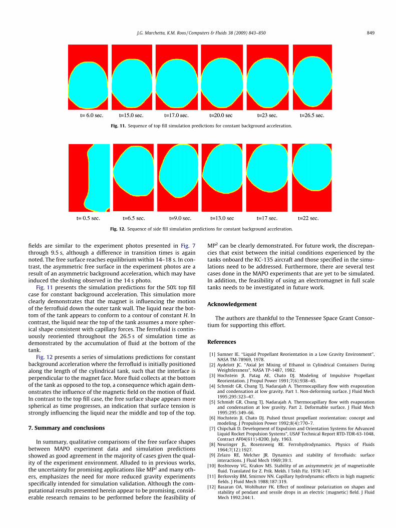
Fig. 11. Sequence of top fill simulation predictions for constant background acceleration.
Fig. 12. Sequence of side fill simulation predictions for constant background acceleration.
J.G. Marchetta, K.M. Roos / Computers & Fluids 38 (2009) 843–850 849
fields are similar to the experiment photos presented in Fig. 7through 9.5 s, although a difference in transition times is againnoted. The free surface reaches equilibrium within 14–18 s. In con-trast, the asymmetric free surface in the experiment photos are aresult of an asymmetric background acceleration, which may haveinduced the sloshing observed in the 14 s photo.
Fig. 11 presents the simulation predictions for the 50% top fillcase for constant background acceleration. This simulation moreclearly demonstrates that the magnet is influencing the motionof the ferrofluid down the outer tank wall. The liquid near the bot-tom of the tank appears to conform to a contour of constant H. Incontrast, the liquid near the top of the tank assumes a more spher-ical shape consistent with capillary forces. The ferrofluid is contin-uously reoriented throughout the 26.5 s of simulation time asdemonstrated by the accumulation of fluid at the bottom of thetank.
Fig. 12 presents a series of simulations predictions for constantbackground acceleration where the ferrofluid is initially positionedalong the length of the cylindrical tank, such that the interface isperpendicular to the magnet face. More fluid collects at the bottomof the tank as opposed to the top, a consequence which again dem-onstrates the influence of the magnetic field on the motion of fluid.In contrast to the top fill case, the free surface shape appears morespherical as time progresses, an indication that surface tension isstrongly influencing the liquid near the middle and top of the top.
7. Summary and conclusions
In summary, qualitative comparisons of the free surface shapesbetween MAPO experiment data and simulation predictionsshowed as good agreement in the majority of cases given the qual-ity of the experiment environment. Alluded to in previous works,the uncertainty for promising applications like MP2 and many oth-ers, emphasizes the need for more reduced gravity experimentsspecifically intended for simulation validation. Although the com-putational results presented herein appear to be promising, consid-erable research remains to be performed before the feasibility of
MP2 can be clearly demonstrated. For future work, the discrepan-cies that exist between the initial conditions experienced by thetanks onboard the KC-135 aircraft and those specified in the simu-lations need to be addressed. Furthermore, there are several testcases done in the MAPO experiments that are yet to be simulated.In addition, the feasibility of using an electromagnet in full scaletanks needs to be investigated in future work.
Acknowledgement
The authors are thankful to the Tennessee Space Grant Consor-tium for supporting this effort.
References
[1] Sumner IE. ‘‘Liquid Propellant Reorientation in a Low Gravity Environment”,NASA TM-78969, 1978.
[2] Aydelott JC. ‘‘Axial Jet Mixing of Ethanol in Cylindrical Containers DuringWeightlessness”, NASA TP-1487, 1982.
[3] Hochstein JI, Patag AE, Chato DJ. Modeling of Impulsive PropellantReorientation. J Propul Power 1991;7(6):938–45.
[4] Schmidt GR, Chung TJ, Nadarajah A. Thermocapillary flow with evaporationand condensation at low gravity. Part 1. Non-deforming surface. J Fluid Mech1995;295:323–47.
[5] Schmidt GR, Chung TJ, Nadarajah A. Thermocapillary flow with evaporationand condensation at low gravity. Part 2. Deformable surface. J Fluid Mech1995;295:349–66.
[6] Hochstein JI, Chato DJ. Pulsed thrust propellant reorientation: concept andmodeling. J Propulsion Power 1992;8(4):770–7.
[7] Chipchak D. Development of Expulsion and Orientation Systems for AdvancedLiquid Rocket Propulsion Systems”, USAF Technical Report RTD-TDR-63-1048,Contract AF04(611)-8200, July, 1963.
[8] Neuringer JL, Rosensweig RE. Ferrohydrodynamics. Physics of Fluids1964;7(12):1927.
[9] Zelazo RE, Melcher JR. Dynamics and stability of ferrofluids: surfaceinteractions. J Fluid Mech 1969;39:1.
[10] Boshtovoy VG, Krakov MS. Stability of an axisymmetric jet of magnetizablefluid. Translated for Z. Prik. Mekh. I Tekh Fiz. 1978:147.
[11] Berkovsky BM, Smirnov NN. Capillary hydrodynamic effects in high magneticfields. J Fluid Mech 1988;187:319.
[12] Basaran OA, Wohlhuter FK. Effect of nonlinear polarization on shapes andstability of pendant and sessile drops in an electric (magnetic) field. J FluidMech 1992;244:1.

850 J.G. Marchetta, K.M. Roos / Computers & Fluids 38 (2009) 843–850
[13] Bashtovoy VG, Berkovsky BM, Vislovich AN. Introduction to thermomechanicsof magnetic fluids. Berlin: Hemisphere Publishing Co; 1988.
[14] Martin JJ, Holt JB. ‘‘Magnetically Actuated Propellant Orientation Experiment,Controlling Fluid Motion With Magnetic Fields in a Low-Gravity Environment”,NASA TM 210129, 2000.
[15] Hochstein JI, Warren RT, Schmidt GR. Magnetically actuated propellantorientation (MAPO) experiment: pre-flight flow field predictions. AIAA Paper97-0570, Jan. 1997.
[16] Marchetta JG, Hochstein JI. Fluid Capture by a Permanent Ring Magnet inReduced Gravity. AIAA Paper 99-0845, Jan. 1999.
[17] Marchetta JG, Hochstein JI. A computational model of magnetic positivepositioning in reduced gravity. IAF Paper ST-99-W.210, Oct. 1999.
[18] Winter AP, Marchetta JG, Hochstein JI. Simulation and Prediction of RealisticMagnetic Positive Positioning for Space Based Fluid Management Systems.AIAA Paper 2004-1151, 2004.
[19] Marchetta JG, Hochstein JI, Simmons BD, Sauter DR.Modeling and Prediction ofMagnetic Storage and Reorientation of Lox in Reduced Gravity. AIAA Paper2002-1005, Jan. 2002.
[20] Kothe DB, Mjolsness RC, Torrey MD. RIPPLE: a computer program forincompressible flows with free surfaces, LANL Report LA-12007-MS, April, 1991.
[21] Fluent Inc.. Fluent 6.1 User’s Guide. Lebanon, NH: Fluent Inc.; 2003.[22] Fluent Inc.. Fluent 6.1 UDF Manual. Lebanon, NH: Fluent Inc.; 2003.[23] Marchetta JG, Hochstein JI, Simmons BD. On-Orbit Positive Positioning of LOX:
Simulation and Correlation. AIAA Paper 2003-1153, Jan. 2003.