Embed Size (px)
Citation preview

SIMULATED PORTFOLIO FOR SEISMIC RISK ASSESSMENT OF COMPOSITE STRUCTURES
Axel Mühlhausen University of Kassel
Kassel, 34125, Germany [email protected]
Uwe Dorka
University of Kassel Kassel, 34125, Germany
ABSTRACT
Assessment of damage costs due to an earthquake is an important issue for the insurance
industry, yet it currently lacks real damage data for realistic pricing of individual risks.
Sophisticated numerical tools, which are widely used to assess structural behavior in great
detail (like FEM), may be used with confidence in modeling damage and therefore, they
may be suitable in seismic risk assessment for insurance purposes.
To produce a virtual damage database, the “Simulated Building Portfolio”-Tool (SBP-Tool)
was developed at the University of Kassel in cooperation with the Munich Re.
This paper presents the first virtual portfolio for steel-concrete composite frame structures.
The SBP-Tool uses beam elements for the composite columns and steel girders, and shell
elements for the concrete slabs. Shear springs are automatically created to model the
composite action between concrete slabs and steel beams. Rotational springs model the
semi-rigid beam-column connections.
INTRODUCTION
The assessment of damage losses due to an earthquake is an important issue for the
insurance and reinsurance industry, but it currently lacks the level of detail that is required
for realistic pricing of individual risks.
Once again, the recent earthquakes that stroke Chile (Maule, Mw 8.8, February 6, 2010),
New Zealand (Darfield, Mw 7.0, September 3, 2010 and Lyttelton, Mw 6.1, February 21,
2011) and Japan (Honshu, Mw 9.0, March 11, 2011) in the last three years proved the
strategic importance of this kind of industry and renewed the crucial question of how to
develop a resilient concept for society.
Any further advancement in that respect is strictly related to the capabilities of creating
reliable models to predict seismic risk. This process implies a better understanding of the
hazard, of the vulnerability and of the exposure that is involved.
Even if important on-going projects, like the Global Earthquake Model (GEM), are aiming at
sharing and improving our knowledge, the “state-of-the-art” of the empirical data-set
regarding earthquake’s economic losses presents a severe non-uniformity. The worldwide
information available is extremely different from both the quality and the geographical
points of view.

Since earthquakes are rare events, the situation will not likely change significantly in the
foreseeable future. It is therefore necessary to further investigate the development of
innovative concepts based on consolidated numerical simulation techniques.
This paper presents how to simulate a first portfolio consisting of steel-concrete composite
structures, which can be used in combination with detailed wave propagation models to
estimate the damage and the resulting damage costs.
[Mazzieri 2013] shows how to describe a spatial variability of strong-ground motions
through large-scale 3D simulations of wave propagation in near-surface soils. He
developed complex 3D FE-models for a region of 1 km x 1 km and a depth of 50 m. More
than 1.000.000 Finite Elements are typically required to simulate the wave propagation in a
particular soil system.
Using these complex soil models, Mazzieri assessed the response of buildings due to the
simulated wave propagation by modeling them as rigid bodies (Figure 1). This neglects the
dynamic characteristics and the non-linear structural behavior of buildings despite being
the controlling factors for the response of buildings under seismic actions.
Fig.1 - Left: 3D-model of the soil and the buildings in Christchurch CBD, [Mazzieri 2013]
Right: Snapshots of the simulated displacement of the buildings of the Christchurch CBD,
[Mazzieri 2013]
A combination of such detailed wave propagation models with sophisticated structural
models for the buildings in question is required, if reliable data for seismic risk analysis is to
be provided.
THE SBP-TOOL FOR GENERATING A VIRTUAL PORTFOLIO
To create this kind of building models, the so-called “Simulated Building Portfolio-Tool”
(SBP-Tool) was developed at the University of Kassel in cooperation with the Munich Re,
[Mühlhausen 2011, 2012]. It provides a virtual portfolio of realistic buildings by using a set
of global building criteria provided by the user in a configuration file. A statistical process
automatically generates each individual building for the portfolio using the given range for
each criterion.

Fig. 2 - Import new routines to generic SBP-Tool
The program is written in ISO C99 and features a modular design (Figure 2). This allows
for easy adaptation to different structures (masonry, steel frames, rc-frames with masonry
infill, etc.) and inclusion of additional building features, like stairs or penthouses. Currently,
the SBP-Tool is used to generate 3D linear FE-models of masonry buildings (Figure 3) and
as a recent addition, steel-concrete composite frame structures. A detailed description of
how to generate the sophisticated steel-concrete composite frame structures with the pre-
design (static) module is given in the following chapter.
Fig. 3. - A regional portfolio of 3D FE-models for masonry buildings simulated with the
SBP-Tool. This can be combined with any seismic input, e.g. wave propagation models
Whereas the first file (a configuration file) does not depend on any particular FE-software,
the second one, the output, must be adapted to its specific commands. This allows the use
of other FE-software (Ansys, Open Quake, SLang etc.) without interfering with the initial
generation process of the buildings.
SLang imports the ASCII files and, by executing the commands, it creates the mass and
stiffness matrices. They are exported as two additional output files. Furthermore, SLang
creates a file with all the information associated with each DOF. Thus, a set of 4 files is
created for each building generated containing all the necessary information to perform a
dynamic analysis, and in particular a time history analysis.
In general (e.g. non-linear structures) around 500 time histories are required to determine
the standard deviation of a local variable with an accuracy of greater than 99 % according
to the central limit theorem.
That means for a given portfolio like the one in figure 4 with 65 buildings and approximately
1.700.000 DOFs, 8.500.000 time histories are required. To compute 8.500.000 time

histories in a short period of time, the use of an efficient algorithm in combination with
parallel computing is necessary.
In the case of linear structures, the use of power spectra provides an efficient way to
calculate the required statistical values of local variables, which can be obtained by
multiplying the transfer function of the local variable with the power spectrum of the input
process (ground motion).
STEEL-CONCRETE COMPOSITE FRAME STRUCTURES WITHIN THE SBP-TOOL
A composite structure combines two or more materials with each other and is a widely
used structural system in buildings and bridges.
Nowadays, a wide range of materials can be used in composite structures, like wood and
concrete (especially ultra high performance concrete), but the most common way is
combining steel and concrete for manufacturing composite columns, composite beams and
composite slabs.
The main purpose of combining different materials is to take advantage of the strengths of
each material despite the different mechanical properties and their individual weaknesses;
for example while one material can be efficient in tension (e.g. steel) the other one (like
concrete) would be efficient in compression.
Further advantages of using steel-concrete composite structures are that concrete provides
a good protection against corrosion and high temperature (fire). The use of steel-concrete
composite structures can result in a more efficient design in comparison with steel or
concrete structures alone. Usually, larger spans can be reached when a concrete-steel
composite system is chosen [Bode,1998, Huber, 2000].
Fig. 4 – A sketch of a steel-concrete composite slab, [Duowei webpage]
Concrete Slab
Profiled steel decking
Shear studs
Steel girder
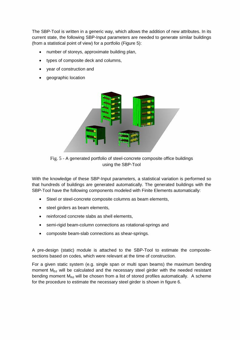
The SBP-Tool is written in a generic way, which allows the addition of new attributes. In its
current state, the following SBP-Input parameters are needed to generate similar buildings
(from a statistical point of view) for a portfolio (Figure 5):
number of storeys, approximate building plan,
types of composite deck and columns,
year of construction and
geographic location
Fig. 5 - A generated portfolio of steel-concrete composite office buildings
using the SBP-Tool
With the knowledge of these SBP-Input parameters, a statistical variation is performed so
that hundreds of buildings are generated automatically. The generated buildings with the
SBP-Tool have the following components modeled with Finite Elements automatically:
Steel or steel-concrete composite columns as beam elements,
steel girders as beam elements,
reinforced concrete slabs as shell elements,
semi-rigid beam-column connections as rotational-springs and
composite beam-slab connections as shear-springs.
A pre-design (static) module is attached to the SBP-Tool to estimate the composite-
sections based on codes, which were relevant at the time of construction.
For a given static system (e.g. single span or multi span beams) the maximum bending
moment MEd will be calculated and the necessary steel girder with the needed resistant
bending moment MRd will be chosen from a list of stored profiles automatically. A scheme
for the procedure to estimate the necessary steel girder is shown in figure 6.

Fig. 6 – 3D-FE model (left) for a composite frame. Static system of red part is shown in the
middle and an extract of the available profiles is shown on the right.
One of the most important aspects of modeling composite structures are the connections
between different materials (steel and concrete) and different composite members (beams
to columns). To model the beam-slab connections between the steel girder and concrete
slab and the semi-rigid beam-column connections, shear springs and rotational springs are
used respectively and modeled with the Finite Element software SLang. In figure 7 a three
and a four storey frame building is shown.
Fig. 7 – FE-models for a three and four storey steel-concrete composite frame building
THE PORTFOLIO SIMULATION
To perform the time history analysis with the required efficiency and speed, a parallel
implementation of Dorka's substructure algorithm [Dorka 1991, 2002], [Bayer et al. 2005] is
needed and given in Figure 8 as a flowchart. On the left is shown the linear control
mechanism and on the right the flowchart of substructure algorithm.

Fig. 8 – Substructure algorithm with digital feedback and error force compensation, [Dorka
2002]
This algorithm is a discrete formulation of the dynamic equilibrium equation (1):
(1)
Its integration constants and are variables. With = 0.5 and = 0.25, it becomes the
well-known Newmark scheme. It also accommodates experimental and non-linear
numerical restoring forces fr+fs through a parallel sub-stepping process within each time
step, thus avoiding time-consuming matrix inversions and iterations. Therefore, this
algorithm, which is called “Open hybrid simulation library” (OpenHySL), can take
advantage of multi-core and multi-processor computers using parallel libraries and other
optimizations, resulting in solving 10000 DOFs in 43,94 ms per time step on a regular
laptop computer [Obón Santacana 2012]. This is because the sub-stepping within each
time step does not cause any significant reduction in performance due to its parallel
implementation if an adequate number of cores or processors are available.
The time histories are stored in a HDF5 format with all necessary information for the time
parameters (date, duration, number of DOF, number of time steps and duration of time
step) and for the time integration (acceleration, velocity, displacement and stresses) for
further processing, e.g. Matlab.
ILLUSTRATIVE EXAMPLE
To demonstrate this developed approach to estimate economic losses for single risks or
whole portfolios, an illustrative example for a 3 storey office building is chosen. This case
study is conducted with a return period of 475 only, but by using several return periods, for
2
r s
d u duM +C +Ku = p(t)+ f + f
dt dt

example 10, 20, 50, 100, 200, 1000 and 2000 years, a loss curve for a single risk or
portfolio can be produced.
Loss curves are the ratio between repair costs and return period and they are an important
tool for the insurance and reinsurance industry for calculating the local premium. An
economic loss of a single risk is reached much earlier than the mechanical collapse, so it is
important to notice that the focus of this study lies on economic aspects not safety aspects.
The following assumptions are made to demonstrate this approach on a 3 storey-office
building located in the city centre of Potenza (Italy). To describe the hazard for this
building, two parameters are used: the local soil and the peak ground acceleration (PGA).
For the region of Potenza, the reference PGA has a value of 0,275g for a return period of
475 years. For this seismic hazard, time histories in x- and y-direction are generated
artificially and are shown in Figure 9 with a maximum of ca. 3 m/s².
Fig. 9 – Artificially generated time histories in x- and y-direction for the chosen location
(Potenza, Italy) and seismic hazard level
The office building was generated with the SBP-Tool based on the following specific criteria
(compare general criteria chapter 5):
number of storeys: 3 storeys, storey height 4m
approximate building plan: 21m by 6m,
types of composite deck: Solid steel-concrete composite deck with steel H-sections
types of columns: Steel columns
year of construction: 1972 (This defines the building code to be used by the pre-
design (static) module)
geographic location: Potenza, Italy
The pre-design module of the SBP-tool specifies the columns and beams. For this
illustrative example, the profiles are HEA 500 (column) and IPE 400 (beam).
With this information, a FE-model is automatically created with SLang. For this example,
the model was ported to SAP2000 manually in order to use this program’s advanced
visualization capabilities, which Slang is lacking. SAP2000 cannot be used for a full risk

analysis because it cannot utilize the efficient and fast substructure algorithm (Fig. 8),
which is required for a risk simulation within a reasonable time frame.
In SAP2000, a typical plastic hinge is color-coded with its elastic limit in purple, its elastic-
plastic limit in yellow and its plastic limit in brown (Fig. 10). Additional colors were defined
here to describe three damage levels: blue for light damage, light blue for moderate
damage and green for total damage. These must refer to different levels of repair costs in
order to estimate the total damage cost for the whole structure. In this example, they have
been defined close to relevant mechanical states, with a certain need for repair. E.g. the
beginning of global yield will require at least minor repairs after an earthquake whereas
excessive yield will cause the replacement of the corner.
Fig. 10 – Definition of a plastic hinge with elastic limit (purple), elastic-plastic limit (yellow),
plastic limit (brown) and three damage levels (blue, light blue and green).
Fig. 11 – Left: Deformed shape for the sample building from the SAP2000 analysis with
color-coded corners according to Fig. 10 showing many corners with moderate to severe
damage: This structure is likely to be a total economic loss although it will not collapse.

Obviously the function for the repair cost is not linear and steps are not uncommon. In
order to describe the repair function realistically, repair processes must be studied in detail
for the different damage levels, which was not done here. Therefore, the results presented
in Fig. 11 are only an illustration of the process.
It may be said that most likely this 3-storey office building is a total economic loss for this
seismic hazard level although collapse is not to be expected: The hinges in the first floor
are completely plasticized and many other hinges are at least moderately damaged.
Therefore, the repair costs will most likely exceed the value of the structure.
CONCLUSION
Reliable seismic damage and loss simulation not only requires sophisticated seismological
ground models, but foremost detailed structural models, since damage and repair needs
depend on the dynamic characteristics and the local non-linear structural behavior. Virtual
building portfolios consisting of thousands of FE models can now be generated with the
SBP-Tool developed at the University of Kassel. Their seismic risk can be assessed within
a reasonable time frame by using an efficient algorithm, which has been developed for
hybrid simulations in combination with parallel computing.
In order to validate such sophisticated FE-models, mechanically consistent scaling [Dorka
2013] may be used with advantage since it preserves local behavior in a global analysis
without sacrificing computational speed. This has been shown for welded composite beam-
column connections under static loading [Amorntipsakul 2013] and further work is under
way to extend it to cyclic loading.
This will also enable a realistic analysis of local repair costs as a function of certain local
mechanical states that are reached under a certain seismic hazard. This may then lead to
a realistic assessment of economic risk for such structures. Then, realistic virtual portfolios
can be created for steel-concrete composite frame buildings in order to assess damage
costs in regions where no or little event data are available.
REFERENCES
Bayer, V., Dorka, U. E., Füllekrug, U. and Gschwilm J. (2005). On real-time pseudo-dynamic substructure
testing: algorithm, numerical and experimental results”. Aero. Sc. and Tech(9): 223-232.
Brzev, S., Scawthorn. C., Charleson, A.W., Jaiswal, K. (2012) Interim Overview of GEM Building Taxonomy
V2.0, GEM Foundation
Dorka, U.E., Heiland, D. (1991).“ Fast online earthquake simulation using a novel pc supported measurement
and control concept”, Proc. 4th Int. Conf. Structural Dynamics, Southhampton: 636-645.
Dorka, U. E. (2002). “Hybrid experimental - numerical simulation of vibrating structures”, Proceedings of the
International Workshop WAVE 2002: 183 - 191. Okayama, Japan.
Dorka, U. E (2013). “Mechanically consistent scaling of composite beam-column joints”, Advances in
Structural Engineering Vol. 15 No. 9, 1609-1618. DUOWEI, Web page
http://www.duowei.net.cn/en/images/userfiles/1351148949_170.jpg, Accessed 27th
of June 2013 GEM, Web page
http://www.globalquakemodel.org/, Accessed 27th
of February 2013 HDF5, Web page
http://www.hdfgroup.org/HDF5/, Accessed 27th
of February 2013 Mazzieri, I., Stupazzini, M ., Guidotti, R., Smerzini, C. (2013). “SPEED-Spectral Elements in Elastodynamics
with Discontinuous Galerkin: a non-conforming approach for 3D multi-scale problmens”, International

Journal for Numerical Methods in Engineering(2013) ol. 15 No. 9, 1609-1618. itecnico di Milano
Mühlhausen, A., Dorka, U., Smolka, A. and Stupazzini, M. (2011). Improving Seismic Risk Assessment for
the Insurance industry by using 3-D Finite Element Modelling. The 2011 World Congress on Advances in
Structural Engineering and Mechanics, Seoul, South Korea
Mühlhausen, A., Dorka, U., Smolka, A. and Stupazzini, M. (2012). Seismic Risk Assessment for Masonry
Buildings based on Discriminant Analysis of a Virtual Database. Proceeding of the 15th World
Conference on Eartquake Engineering, Lisbon, Portugal
Obón-Santacana, F. and Dorka, U.E. (2012). Effects of Large Numerical Models in Continuous Hybrid
Simulation. Proceeding of the the 15th World Conference on Earthquake Engineering, September 12-17,
2012, Lisbon, Portugal.
SLang – The Sturctural Language (2004), Veit Bayer, Maik Brehm, Christian Bucher, et. Al. Documentation.
Institute of Structural Mechanics - Bauhaus-University Weimar