Embed Size (px)
Citation preview
SimradCP40/42/50 MKIIDGPS Chartplotter
183.0200.202 English
01154.05
Note!Insert or remove C-MAP cartridges ONLY through CHART menu or when unit is off.All electronic navigation equipment is subject to external factors beyond the control of themanufacturer. Therefore such equipment must be regarded as an aid to navigation. Theprudent navigator will, for that reason, never rely on a single source for position fixing andnavigation.
MOB ‘MAN OVERBOARD’ function
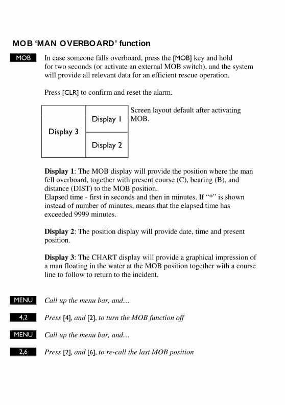
MOB In case someone falls overboard, press the [MOB] key and holdfor two seconds (or activate an external MOB switch), and the systemwill provide all relevant data for an efficient rescue operation.
Press [CLR] to confirm and reset the alarm.
Display 1
Display 3
Display 2
Screen layout default after activatingMOB.
Display 1: The MOB display will provide the position where the manfell overboard, together with present course (C), bearing (B), anddistance (DIST) to the MOB position.Elapsed time - first in seconds and then in minutes. If “*” is showninstead of number of minutes, means that the elapsed time hasexceeded 9999 minutes.
Display 2: The position display will provide date, time and presentposition.
Display 3: The CHART display will provide a graphical impression ofa man floating in the water at the MOB position together with a courseline to follow to return to the incident.
MENU Call up the menu bar, and…
4,2 Press [4], and [2], to turn the MOB function off
MENU Call up the menu bar, and…
2,6 Press [2], and [6], to re-call the last MOB position
CP40/42/50 MKII DGPS Chartplotter Table of contents
1. Introduction and system familiarization1.1 Introduction and system
familiarization, 51.2 Safety summary, 6
2. Fundamentals & initial start-up2.1 Fundamentals of the PAGE and WINdow system, 72.2 Key functions, 102.3 Menu bar, 122.4 Menu layout, 132.5 Choice of symbols, 142.6 Naming of routes, points, etc., 142.7 Initial start-up, 152.8 Turn power off, 16
3. Chart menus and INFO windows3.1 Chart menu, 173.1.1 Charts, 173.2 C-MAP cartridges, 203.3 INFO windows, 223.3.1 Cursor inactive, 223.3.2 Cursor not placed on object or user data, 233.3.3 Cursor placed on waypoint, 243.3.4 Cursor placed on route leg or line leg, 253.3.5 Cursor placed on routepoint or linepoint, 263.3.6 Cursor placed on trackpoint, 273.3.7 Cursor placed on target, 283.3.8 GOTO function, 293.3.9 PLOT function, 303.4 Chart setup, 32
4. Position menus4.1 Position display, 354.2 Set & drift, 394.3 Speed diagram, 404.4 Dual speed display, 414.5 Wind display, 424.6 MOB position, 444.7 Satellite status, 454.8 DGPS setup, 474.9 DSC alarm, 49
5. Waypoint / route menus5.1 WP list, 515.1.1 Delete waypoint via menu, 525.2 Routes stored in the memory, 525.2.1 Delete route via menu, 545.3 Route calculation, 555.4 Lines stored in the memory, 565.4.1 Delete lines via menu, 575.5 Start / stop track, 585.6 Tracks stored in the memory, 595.6.1 Delete tracks via menu, 605.7 Targets stored in the memory, 605.7.1 Delete target via menu, 615.8 Data transfer via DataCard or disc, 62
6. Navigation menus6.1 NAV menu (NAV inactive), 656.1.1 - Navigation display, 656.2 NAV menu – (NAV active), 676.2.1 - Navigation display, 686.2.2 - Navigation setup, 696.2.3 – Turn NAV off, 696.2.4 – ETA & AVN, 696.2.5 – Set & drift trim display, 716.2.6 – Waypoint advance, 716.3 Anchor guard, 726.4 MOB navigation, 736.5 Navigation examples, 73
CP40/42/50 MKII DGPS Chartplotter Table of contents
6.5.1 Chart/cursor navigation, 746.5.2 Waypoint navigation, 756.5.3 Route navigation, 766.5.4 Track navigation, 78
7. ECHO and SPECIAL menus7. Echo menu, 817.1 Depth & temperature diagram, 817.2 Special menu, 837.2.1 Speed alarm, units & language, 837.2.2 Interface setup, NMEA, 857.2.3 Interface setup, alarm/log, 897.2.4 Decca lanes, 907.2.5 Loran C, 917.2.6 Display color, 927.2.7 Factory settings, 93
8. Installation and service8.1 Installation of CP40, 958.2 Installation of CP50, 978.3 Place of installation of display unit, 998.4 Installation of DS40/50, 998.4.1 Operation of DS40/50, 1008.5 Installation of antenna, 1018.6 Electrical connections, 1028.6.1 Power supply connections, 1038.6.2 Fuse, 1038.6.3 NMEA0183 interface conn., 1038.7 Optional connections, 1048.8 Preventive maintenance, 1058.9 Repair and service, 1068.10 Troubleshooting, 1078.11 Specifications, 108
Appendix AGlossary of terms, 111
Appendix BList of datums, 115
Appendix CC-MAP attributes, 117
Index, 123
CE Declaration, 127
International warranty, 129
List of Simrad distributors
CP40/42/50 MKII Introduction and safety summary Chapter 1
5
1.1 Introduction and system familiarization
Congratulations on your purchase of SIMRAD CP40/42/50 MKII DGPSChartplotter - a combination of the latest GPS receiver technology andbuilt-in differential receiver for accurate positioning and prepared forSDGPS, plus: detailed cartography; all in a unique slim-line design with a10” TFT (CP40), a 10” ATFT (CP42), or 14” TFT (CP50) large LCDdisplay in color.
The CP40/42/50 MKII chart system includes a built-in world chart forrough planning and overview. The choice of chart system best suitable forthe CP40/42/50 MKII was carefully singled out to be the C-MAP NTmini cards. The optional C-MAP charts are available world-wide at yourlocal Simrad dealer.
The Global Positioning System is at this time and age the most commonsystem used for navigation and positioning all over the world. Not only formaritime use, but also for land-based applications and aviation.The satellite-based system has been developed and is operated by the USDepartment of Defense in order to provide an accurate and reliableservice, which include a 24-hour global coverage.The GPS system consists of approx. 24 satellites which orbit around theEarth at an altitude of approx. 20,200 km. The satellites transmit perfectlysynchronized data. However, depending on the position, the signals willreach the receiver at a slightly different time. By adding the measured timedifference to the known position of the satellites it is possible to calculatethe ship’s position to within a few meters.
DS40/42/50 Dual Station for the CP40/42/50 is available in 10” black &white or TFT/ATFT color, or in 14” in TFT color.
How to use this manual? The manual is written for the products:CP40, CP42 and CP50, which all share the same type of software.From hereon, these models are referred to as: CPXX.It is a good idea if you make yourself familiar with the key functions,menu structure and rotation of pages (screens) described in chapter 2before you start out, and then proceed with section 2.7 Initial start-up.For quick location of a certain term, please check the ”Glossary of terms”and the ”Index” at the back of the manual.
CP40/42/50 MKII Introduction and safety summary Chapter 1
6
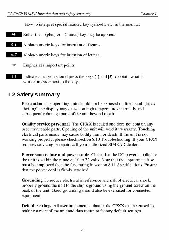
How to interpret special marked key symbols, etc. in the manual:
+/- Either the + (plus) or – (minus) key may be applied.
0-9 Alpha-numeric keys for insertion of figures.
A-Z Alpha-numeric keys for insertion of letters.
Emphasizes important points.
1,3 Indicates that you should press the keys [1] and [3] to obtain what iswritten in italic next to the keys.
1.2 Safety summary
Precaution The operating unit should not be exposed to direct sunlight, as“boiling” the display may cause too high temperatures internally andsubsequently damage parts of the unit beyond repair.
Quality service personnel The CPXX is sealed and does not contain anyuser serviceable parts. Opening of the unit will void its warranty. Touchingelectrical parts inside may cause bodily harm or death. If the unit is notworking properly, please check section 8.10 Troubleshooting. If your CPXXrequires servicing or repair, call your authorized SIMRAD dealer.
Power source, fuse and power cable Check that the DC power supplied tothe unit is within the range of 10 to 32 volts. Note that the appropriate fusemust be employed (see the fuse rating in section 8.11 Specifications. Ensurethat the power cord is firmly attached.
Grounding To reduce electrical interference and risk of electrical shock,properly ground the unit to the ship’s ground using the ground screw on theback of the unit. Good grounding should also be exercised for connectedequipment.
Default settings All user implemented data in the CPXX can be erased bymaking a reset of the unit and thus return to factory default settings.
CP40/42/50 MKII Fundamentals & initial start-up Chapter 2
7
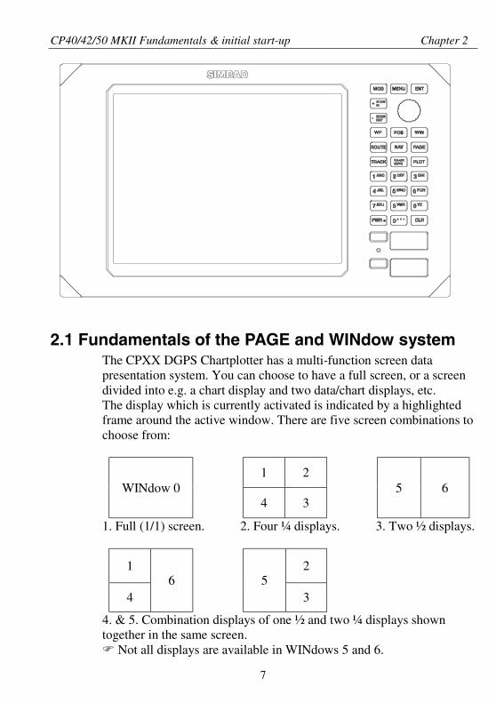
2.1 Fundamentals of the PAGE and WINdow systemThe CPXX DGPS Chartplotter has a multi-function screen datapresentation system. You can choose to have a full screen, or a screendivided into e.g. a chart display and two data/chart displays, etc.The display which is currently activated is indicated by a highlightedframe around the active window. There are five screen combinations tochoose from:
1 2WINdow 0
4 35 6
1. Full (1/1) screen. 2. Four ¼ displays. 3. Two ½ displays.
1 2
46 5
3
4. & 5. Combination displays of one ½ and two ¼ displays showntogether in the same screen.
Not all displays are available in WINdows 5 and 6.
CP40/42/50 MKII Fundamentals & initial start-up Chapter 2
8
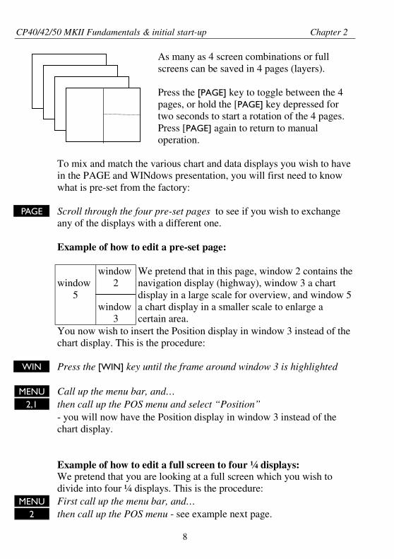
As many as 4 screen combinations or fullscreens can be saved in 4 pages (layers).
Press the [PAGE] key to toggle between the 4pages, or hold the [PAGE] key depressed fortwo seconds to start a rotation of the 4 pages.Press [PAGE] again to return to manualoperation.
To mix and match the various chart and data displays you wish to havein the PAGE and WINdows presentation, you will first need to knowwhat is pre-set from the factory:
PAGE Scroll through the four pre-set pages to see if you wish to exchangeany of the displays with a different one.
Example of how to edit a pre-set page:
window5
window2
window3
We pretend that in this page, window 2 contains thenavigation display (highway), window 3 a chartdisplay in a large scale for overview, and window 5a chart display in a smaller scale to enlarge acertain area.
You now wish to insert the Position display in window 3 instead of thechart display. This is the procedure:
WIN Press the [WIN] key until the frame around window 3 is highlighted
MENU Call up the menu bar, and…2,1 then call up the POS menu and select “Position”
- you will now have the Position display in window 3 instead of thechart display.
Example of how to edit a full screen to four ¼ displays:We pretend that you are looking at a full screen which you wish todivide into four ¼ displays. This is the procedure:
MENU First call up the menu bar, and…2 then call up the POS menu - see example next page.
CP40/42/50 MKII Fundamentals & initial start-up Chapter 2
9
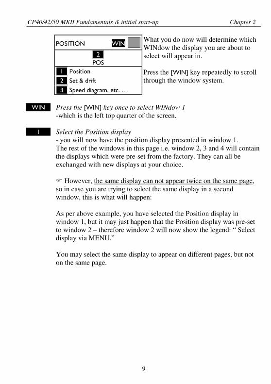
POSITION
WIN
_2_POS
_1_ Position
_2_ Set & drift
_3_ Speed diagram, etc. …
What you do now will determine whichWINdow the display you are about toselect will appear in.
Press the [WIN] key repeatedly to scrollthrough the window system.
WIN Press the [WIN] key once to select WINdow 1-which is the left top quarter of the screen.
1 Select the Position display- you will now have the position display presented in window 1.The rest of the windows in this page i.e. window 2, 3 and 4 will containthe displays which were pre-set from the factory. They can all beexchanged with new displays at your choice.
However, the same display can not appear twice on the same page,so in case you are trying to select the same display in a secondwindow, this is what will happen:
As per above example, you have selected the Position display inwindow 1, but it may just happen that the Position display was pre-setto window 2 – therefore window 2 will now show the legend: “ Selectdisplay via MENU.”
You may select the same display to appear on different pages, but noton the same page.
CP40/42/50 MKII Fundamentals & initial start-up Chapter 2
10
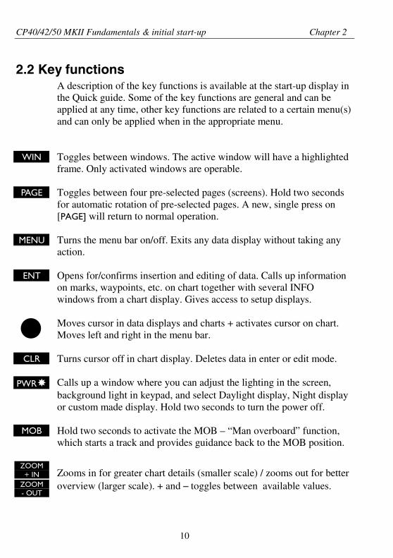
2.2 Key functionsA description of the key functions is available at the start-up display inthe Quick guide. Some of the key functions are general and can beapplied at any time, other key functions are related to a certain menu(s)and can only be applied when in the appropriate menu.
WIN Toggles between windows. The active window will have a highlightedframe. Only activated windows are operable.
PAGE Toggles between four pre-selected pages (screens). Hold two secondsfor automatic rotation of pre-selected pages. A new, single press on[PAGE] will return to normal operation.
MENU Turns the menu bar on/off. Exits any data display without taking anyaction.
ENT Opens for/confirms insertion and editing of data. Calls up informationon marks, waypoints, etc. on chart together with several INFOwindows from a chart display. Gives access to setup displays.
Moves cursor in data displays and charts + activates cursor on chart.Moves left and right in the menu bar.
CLR Turns cursor off in chart display. Deletes data in enter or edit mode.
PWR Calls up a window where you can adjust the lighting in the screen,background light in keypad, and select Daylight display, Night displayor custom made display. Hold two seconds to turn the power off.
MOB Hold two seconds to activate the MOB – “Man overboard” function,which starts a track and provides guidance back to the MOB position.
ZOOM+ IN Zooms in for greater chart details (smaller scale) / zooms out for better
ZOOM- OUT
overview (larger scale). + and – toggles between available values.
CP40/42/50 MKII Fundamentals & initial start-up Chapter 2
11
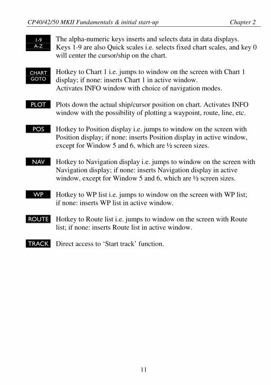
1-9A-Z
The alpha-numeric keys inserts and selects data in data displays.Keys 1-9 are also Quick scales i.e. selects fixed chart scales, and key 0will center the cursor/ship on the chart.
CHARTGOTO
Hotkey to Chart 1 i.e. jumps to window on the screen with Chart 1display; if none: inserts Chart 1 in active window.Activates INFO window with choice of navigation modes.
PLOT Plots down the actual ship/cursor position on chart. Activates INFOwindow with the possibility of plotting a waypoint, route, line, etc.
POS Hotkey to Position display i.e. jumps to window on the screen withPosition display; if none: inserts Position display in active window,except for Window 5 and 6, which are ½ screen sizes.
NAV Hotkey to Navigation display i.e. jumps to window on the screen withNavigation display; if none: inserts Navigation display in activewindow, except for Window 5 and 6, which are ½ screen sizes.
WP Hotkey to WP list i.e. jumps to window on the screen with WP list;if none: inserts WP list in active window.
ROUTE Hotkey to Route list i.e. jumps to window on the screen with Routelist; if none: inserts Route list in active window.
TRACK Direct access to ‘Start track’ function.
CP40/42/50 MKII Fundamentals & initial start-up Chapter 2
12
2.3 Menu bar
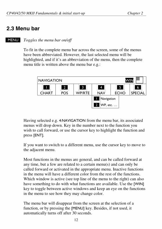
MENU Toggles the menu bar on/off
To fit in the complete menu bar across the screen, some of the menushave been abbreviated. However, the last selected menu will behighlighted, and if it’s an abbreviation of the menu, then the completemenu title is written above the menu bar e.g.:
NAVIGATION
WIN
_1_
CHART
_2_
POS
_3_
WP/RTE
_4_
NAV
_5_
ECHO
_6_
SPECIAL_1_ Navigation
_2_ WP, etc. …
Having selected e.g. 4:NAVIGATION from the menu bar, its associatedmenus will drop down. Key in the number next to the function youwish to call forward, or use the cursor key to highlight the function andpress [ENT].
If you want to switch to a different menu, use the cursor key to move tothe adjacent menu.
Most functions in the menus are general, and can be called forward atany time, but a few are related to a certain menu(s) and can only becalled forward or activated in the appropriate menu. Inactive functionsin the menu will have a different color from the rest of the functions.Which window is active (see top line of the menu to the right) can alsohave something to do with what functions are available. Use the [WIN]key to toggle between active windows and keep an eye on the functionsin the menu to see how they may change color.
The menu bar will disappear from the screen at the selection of afunction, or by pressing the [MENU] key. Besides, if not used, itautomatically turns off after 30 seconds.
CP40/42/50 MKII Fundamentals & initial start-up Chapter 2
13
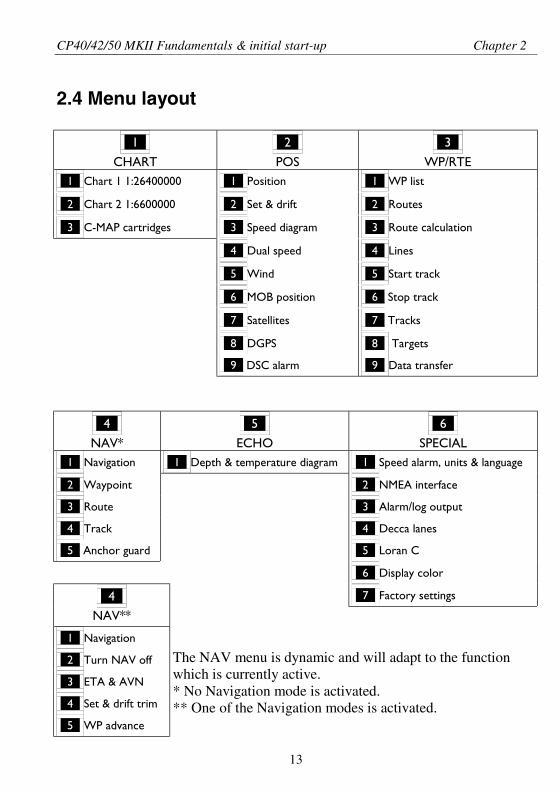
2.4 Menu layout
_1_
CHART
_2_
POS
_3_
WP/RTE_1_ Chart 1 1:26400000 _1_ Position _1_ WP list
_2_ Chart 2 1:6600000 _2_ Set & drift _2_ Routes
_3_ C-MAP cartridges _3_ Speed diagram _3_ Route calculation
_4_ Dual speed _4_ Lines
_5_ Wind _5_ Start track
_6_ MOB position _6_ Stop track
_7_ Satellites _7_ Tracks
_8_ DGPS _8_ Targets
_9_ DSC alarm _9_ Data transfer
_4_
NAV*
_5_
ECHO
_6_
SPECIAL_1_ Navigation _1_ Depth & temperature diagram _1_ Speed alarm, units & language
_2_ Waypoint _2_ NMEA interface
_3_ Route _3_ Alarm/log output
_4_ Track _4_ Decca lanes
_5_ Anchor guard _5_ Loran C
_6_ Display color
_7_ Factory settings_4_
NAV**
_1_ Navigation
_2_ Turn NAV off
_3_ ETA & AVN
_4_ Set & drift trim
_5_ WP advance
The NAV menu is dynamic and will adapt to the functionwhich is currently active.* No Navigation mode is activated.** One of the Navigation modes is activated.
CP40/42/50 MKII Fundamentals & initial start-up Chapter 2
14
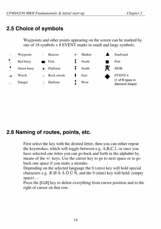
2.5 Choice of symbols
Waypoints and other points appearing on the screen can be marked byone of 18 symbols + 8 EVENT marks in small and large symbols:
2.6 Naming of routes, points, etc.
First select the key with the desired letter, then you can either repeatthe keystrokes, which will toggle between e.g. A,B,C,1, or once youhave selected one letter you can go back and forth in the alphabet bymeans of the +/- keys. Use the cursor key to go to next space or to goback one space if you make a mistake.Depending on the selected language the 0 (zero) key will hold specialcharacters e.g. Æ Ø Å Ä Ö Ü Ñ, and the 9 (nine) key will hold: (emptyspace) . -Press the [CLR] key to delete everything from cursor position and to theright of cursor on that row.
Waypoint
Red buoy
Green buoy
Wreck
Danger
Beacon
Fish
Platform
Rock awash
Harbour
Marker
North
South
East
West
Starboard
Port
MOB
EVENT 4(1 of 8 types indiamond shape)
CP40/42/50 MKII Fundamentals & initial start-up Chapter 2
15
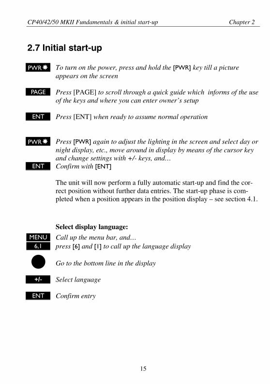
2.7 Initial start-up
PWR To turn on the power, press and hold the [PWR] key till a pictureappears on the screen
PAGE Press [PAGE] to scroll through a quick guide which informs of the useof the keys and where you can enter owner’s setup
ENT Press [ENT] when ready to assume normal operation
PWR Press [PWR] again to adjust the lighting in the screen and select day ornight display, etc., move around in display by means of the cursor keyand change settings with +/- keys, and…
ENT Confirm with [ENT]
The unit will now perform a fully automatic start-up and find the cor-rect position without further data entries. The start-up phase is com-pleted when a position appears in the position display – see section 4.1.
Select display language:MENU Call up the menu bar, and…
6,1 press [6] and [1] to call up the language display
Go to the bottom line in the display
+/- Select language
ENT Confirm entry
CP40/42/50 MKII Fundamentals & initial start-up Chapter 2
16
2.8 Turn power off
PWR Call up INFO window, and…
PWR Press and hold until screen turns black
The CPXX is now turned off. All data and setups are saved and storedin the internal memory and, of course, will be available next time theunit is turned on.
CP40/42/50 MKII Chart menus and INFO windows Chapter 3
17
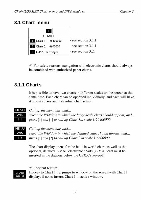
3.1 Chart menu
_1_
CHART_1_ Chart 1 1:26400000 - see section 3.1.1.
_2_ Chart 2 1:6600000 - see section 3.1.1.
_3_ C-MAP cartridges - see section 3.2.
For safety reasons, navigation with electronic charts should alwaysbe combined with authorized paper charts.
3.1.1 Charts
It is possible to have two charts in different scales on the screen at thesame time. Each chart can be operated individually, and each will haveit’s own cursor and individual chart setup.
MENU Call up the menu bar, and…WIN select the WINdow in which the large-scale chart should appear, and…1,1 press [1] and [1] to call up Chart 1in scale 1:26400000
MENU Call up the menu bar, and…WIN select the WINdow in which the detailed chart should appear, and…1,2 press [1] and [2] to call up Chart 2 in scale 1:6600000
The chart display opens for the built-in world chart, as well as theoptional, detailed C-MAP electronic charts (C-MAP cart must beinserted in the drawers below the CPXX’s keypad).
Shortcut feature:CHARTGOTO
Hotkey to Chart 1 i.e. jumps to window on the screen with Chart 1display; if none: inserts Chart 1 in active window.
CP40/42/50 MKII Chart menus and INFO windows Chapter 3
18
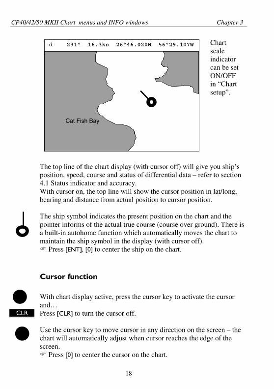
d 231° 16.3kn 26°46.020N 56°29.107W
Cat Fish Bay
The top line of the chart display (with cursor off) will give you ship’sposition, speed, course and status of differential data – refer to section4.1 Status indicator and accuracy.With cursor on, the top line will show the cursor position in lat/long,bearing and distance from actual position to cursor position.
The ship symbol indicates the present position on the chart and thepointer informs of the actual true course (course over ground). There isa built-in autohome function which automatically moves the chart tomaintain the ship symbol in the display (with cursor off).
Press [ENT], [0] to center the ship on the chart.
Cursor function
With chart display active, press the cursor key to activate the cursorand…
CLR Press [CLR] to turn the cursor off.
Use the cursor key to move cursor in any direction on the screen – thechart will automatically adjust when cursor reaches the edge of thescreen.
Press [0] to center the cursor on the chart.
Chartscaleindicatorcan be setON/OFFin “Chartsetup”.
CP40/42/50 MKII Chart menus and INFO windows Chapter 3
19
In data displays the cursor will be shown in form of a ruling boxaround the active field.
Zoom function – with cursor on, the zoom function will zoom aroundthe cursor. With cursor off, the zoom function will zoom around theship´s position.
ZOOM + IN Zoom in for details (smaller scale)
ZOOM- OUT Zoom out for overview (greater scale)
1-9 Use one of the shortcut keys to quickly change the chart scale:
Press [1] = 1:6.600.000,[4] = 1:200.000,[7] = 1:6.000,
[2] = 1:2.000.000,[5] = 1:60.000,[8] = 1:2.000,
[3] = 1:600.000,[6] = 1:20.000,[9] = 1:600
Chart details may not be available in all scales in all areas. Non-covered areas will be marked as hatched or all blue with coordinategrid (with grid set to AUTO in chart setup), depending on the actualscale. See section 3.4 Chart setup for more details on what you mightwant to see in the chart and not see.
The built-in world chart can be zoomed up/down in six steps from ascale of approx. 1:33,000,000 to 1:2,000,000.
An over-zoom function enables you to zoom beyond the chart, whichautomatically is switched off and replaced by a lat/long coordinategrid. In this mode the scale can go down to 1:600.
CP40/42/50 MKII Chart menus and INFO windows Chapter 3
20
3.2 C-MAP cartridges
On the front of the CPXX below the keypad are two small watertightdrawers wherein you place the C-MAP cartridge(s) you wish to load.
Do not attempt to insert or remove cartridges unless the CPXX isturned off, or chart reading is in stand-by:
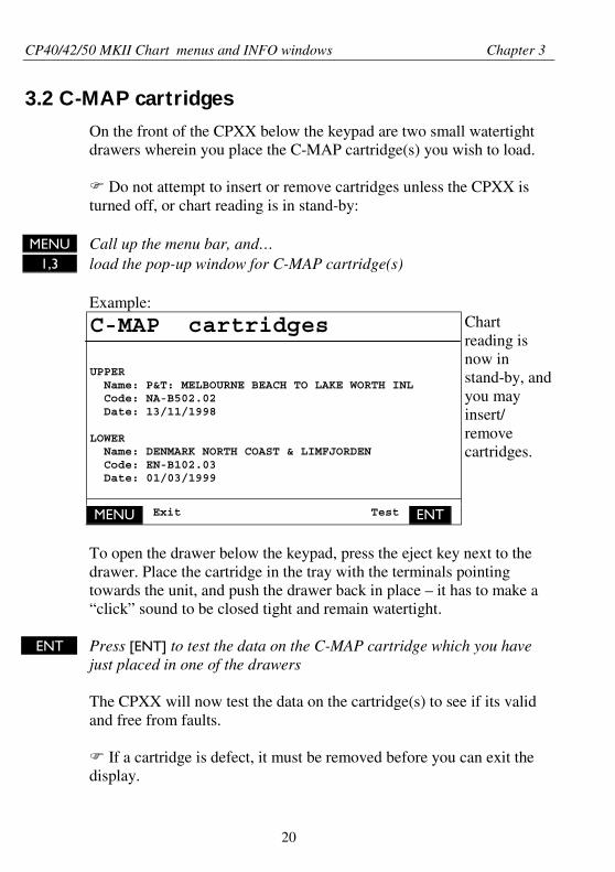
MENU Call up the menu bar, and…1,3 load the pop-up window for C-MAP cartridge(s)
Example:
C-MAP cartridges
UPPER Name: P&T: MELBOURNE BEACH TO LAKE WORTH INL Code: NA-B502.02 Date: 13/11/1998
LOWER Name: DENMARK NORTH COAST & LIMFJORDEN Code: EN-B102.03 Date: 01/03/1999
Chartreading isnow instand-by, andyou mayinsert/removecartridges.
MENU Exit Test ENT
To open the drawer below the keypad, press the eject key next to thedrawer. Place the cartridge in the tray with the terminals pointingtowards the unit, and push the drawer back in place – it has to make a“click” sound to be closed tight and remain watertight.
ENT Press [ENT] to test the data on the C-MAP cartridge which you havejust placed in one of the drawers
The CPXX will now test the data on the cartridge(s) to see if its validand free from faults.
If a cartridge is defect, it must be removed before you can exit thedisplay.
CP40/42/50 MKII Chart menus and INFO windows Chapter 3
21
MENU Return to chart display
In addition to the larger boundaries of the world chart there will beseparate boundary lines for the individual charts stored on the samecartridge. However, the boundary lines for the C-MAP chart areas canbe turned off, so they will not be visible on the chart – refer to Chartsetup.Other chart areas can quickly be reached by means of the zoom keys:
ZOOM- OUT Zoom out until desired area becomes visible
Move cursor to approximate area, and…
ZOOM+ IN Zoom in
The chart will automatically start to move when cursor reaches theedge of the screen. When cursor is switched off [CLR], the chart willreturn to ship’s position.
See also section 3.4 Chart setup.
CP40/42/50 MKII Chart menus and INFO windows Chapter 3
22
3.3 INFO windows
A number of pop-up INFO windows are available mainly from activechart display. Only a few of the functions in the INFO windows can beaccessed from data displays and other displays. Refer to sections 3.3.x.
3.3.1 Cursor inactive
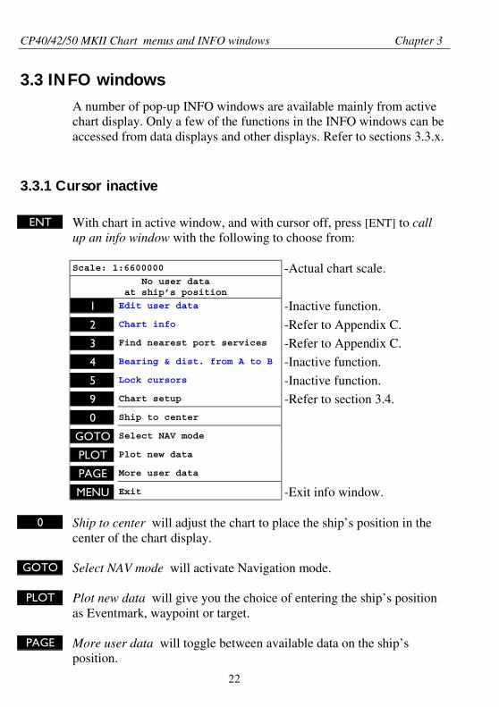
ENT With chart in active window, and with cursor off, press [ENT] to callup an info window with the following to choose from:
Scale: 1:6600000 -Actual chart scale.No user data
at ship’s position
1 Edit user data -Inactive function.
2 Chart info -Refer to Appendix C.3 Find nearest port services -Refer to Appendix C.
4 Bearing & dist. from A to B -Inactive function.
5 Lock cursors -Inactive function.
9 Chart setup -Refer to section 3.4.
0 Ship to center
GOTO Select NAV mode
PLOT Plot new data
PAGE More user data
MENU Exit -Exit info window.
0 Ship to center will adjust the chart to place the ship’s position in thecenter of the chart display.
GOTO Select NAV mode will activate Navigation mode.
PLOT Plot new data will give you the choice of entering the ship’s positionas Eventmark, waypoint or target.
PAGE More user data will toggle between available data on the ship’sposition.
CP40/42/50 MKII Chart menus and INFO windows Chapter 3
23
3.3.2 Cursor active but not placed on any object or data
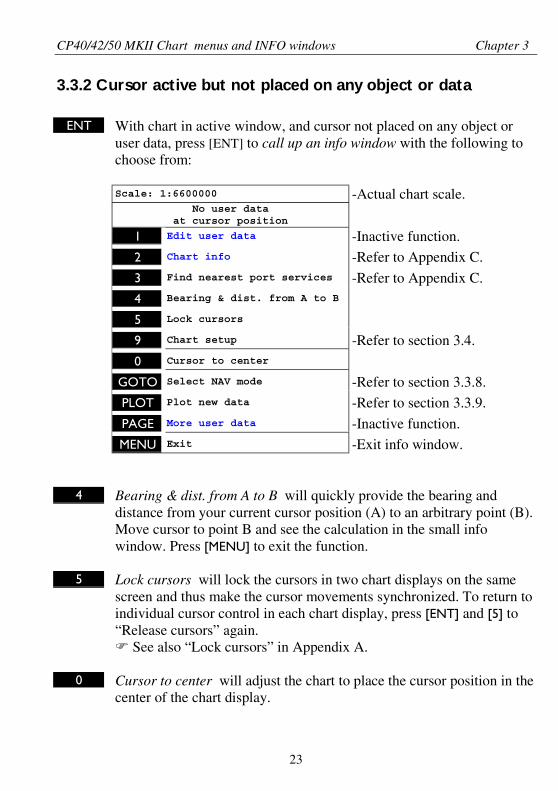
ENT With chart in active window, and cursor not placed on any object oruser data, press [ENT] to call up an info window with the following tochoose from:
Scale: 1:6600000 -Actual chart scale.No user data
at cursor position
1 Edit user data -Inactive function.
2 Chart info -Refer to Appendix C.
3 Find nearest port services -Refer to Appendix C.4 Bearing & dist. from A to B
5 Lock cursors
9 Chart setup -Refer to section 3.4.
0 Cursor to center
GOTO Select NAV mode -Refer to section 3.3.8.PLOT Plot new data -Refer to section 3.3.9.
PAGE More user data -Inactive function.MENU Exit -Exit info window.
4 Bearing & dist. from A to B will quickly provide the bearing anddistance from your current cursor position (A) to an arbitrary point (B).Move cursor to point B and see the calculation in the small infowindow. Press [MENU] to exit the function.
5 Lock cursors will lock the cursors in two chart displays on the samescreen and thus make the cursor movements synchronized. To return toindividual cursor control in each chart display, press [ENT] and [5] to“Release cursors” again.
See also “Lock cursors” in Appendix A.
0 Cursor to center will adjust the chart to place the cursor position in thecenter of the chart display.
CP40/42/50 MKII Chart menus and INFO windows Chapter 3
24
3.3.3 Cursor placed on waypoint
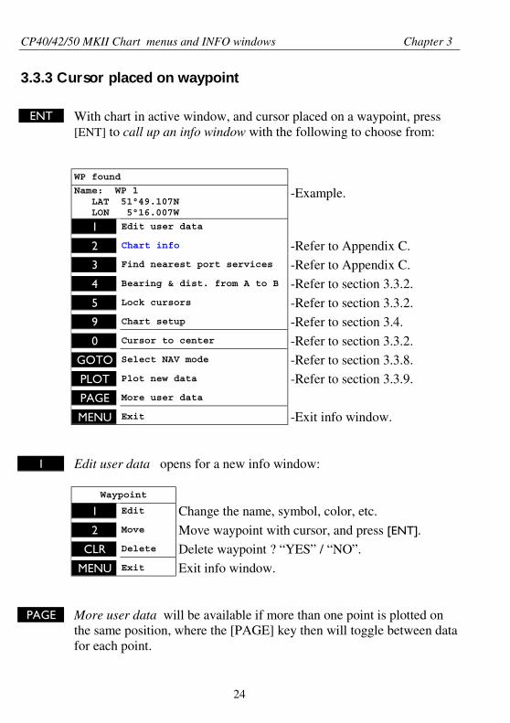
ENT With chart in active window, and cursor placed on a waypoint, press[ENT] to call up an info window with the following to choose from:
WP found
Name: WP 1 LAT 51°49.107N LON 5°16.007W
-Example.
1 Edit user data
2 Chart info -Refer to Appendix C.3 Find nearest port services -Refer to Appendix C.
4 Bearing & dist. from A to B -Refer to section 3.3.2.
5 Lock cursors -Refer to section 3.3.2.9 Chart setup -Refer to section 3.4.
0 Cursor to center -Refer to section 3.3.2.GOTO Select NAV mode -Refer to section 3.3.8.
PLOT Plot new data -Refer to section 3.3.9.
PAGE More user data
MENU Exit -Exit info window.
1 Edit user data opens for a new info window:
Waypoint
1 Edit Change the name, symbol, color, etc.
2 Move Move waypoint with cursor, and press [ENT].
CLR Delete Delete waypoint ? “YES” / “NO”.
MENU Exit Exit info window.
PAGE More user data will be available if more than one point is plotted onthe same position, where the [PAGE] key then will toggle between datafor each point.
CP40/42/50 MKII Chart menus and INFO windows Chapter 3
25
3.3.4 Cursor placed on route leg or line leg
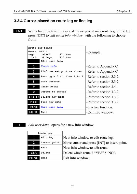
ENT With chart in active display and cursor placed on a route leg or line leg,press [ENT] to call up an info window with the following to choosefrom:
Route leg found
Name: RTE 1Leg: B336° 77.16nmTotal: 4 legs 215.6nm
-Example.
1 Edit user data
2 Chart info -Refer to Appendix C.
3 Find nearest port services -Refer to Appendix C.4 Bearing & dist. from A to B -Refer to section 3.3.2.
5 Lock cursors -Refer to section 3.3.2.
9 Chart setup -Refer to section 3.4.
0 Cursor to center -Refer to section 3.3.2.
GOTO Select NAV mode -Refer to section 3.3.8.PLOT Plot new data -Refer to section 3.3.9.
PAGE More user data -Inactive function.MENU Exit -Exit info window.
1 Edit user data opens for a new info window:
Route leg
1 Edit leg New info window to edit route leg.2 Insert point Move cursor and press [ENT] to insert point.
3 Edit New info window to edit route.CLR Delete Delete whole route ? “YES” / “NO”.
MENU Exit Exit info window.
CP40/42/50 MKII Chart menus and INFO windows Chapter 3
26
3.3.5 Cursor placed on routepoint or linepoint
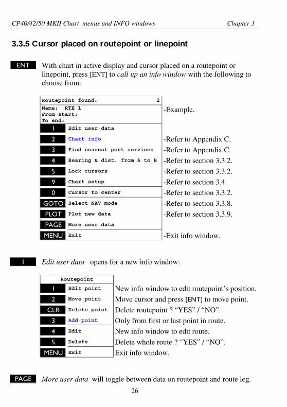
ENT With chart in active display and cursor placed on a routepoint orlinepoint, press [ENT] to call up an info window with the following tochoose from:
Routepoint found: 2
Name: RTE 1From start:To end:
-Example.
1 Edit user data
2 Chart info -Refer to Appendix C.
3 Find nearest port services -Refer to Appendix C.4 Bearing & dist. from A to B -Refer to section 3.3.2.
5 Lock cursors -Refer to section 3.3.2.
9 Chart setup -Refer to section 3.4.
0 Cursor to center -Refer to section 3.3.2.
GOTO Select NAV mode -Refer to section 3.3.8.PLOT Plot new data -Refer to section 3.3.9.
PAGE More user data
MENU Exit -Exit info window.
1 Edit user data opens for a new info window:
Routepoint
1 Edit point New info window to edit routepoint’s position.2 Move point Move cursor and press [ENT] to move point.
CLR Delete point Delete routepoint ? “YES” / “NO”.3 Add point Only from first or last point in route.
4 Edit New info window to edit route.
5 Delete Delete whole route ? “YES” / “NO”.
MENU Exit Exit info window.
PAGE More user data will toggle between data on routepoint and route leg.
CP40/42/50 MKII Chart menus and INFO windows Chapter 3
27
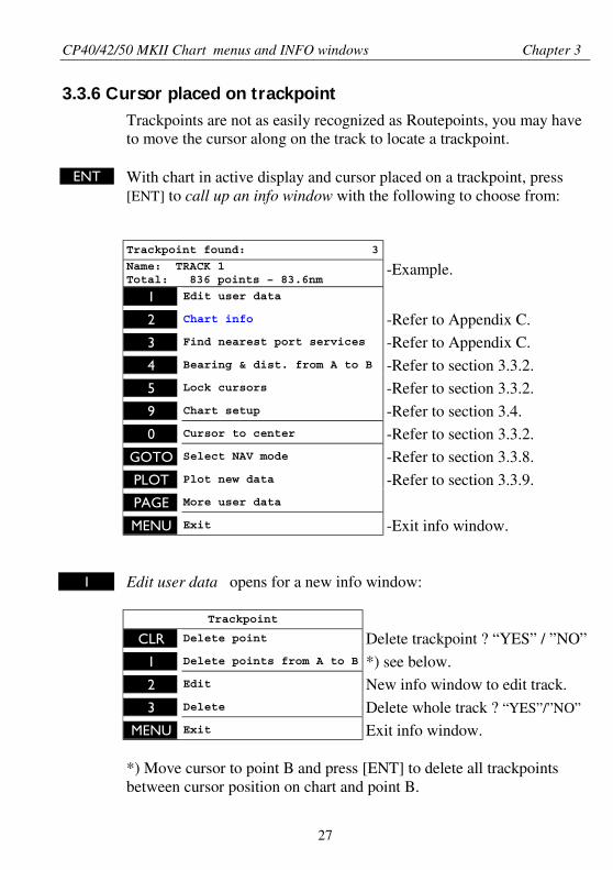
3.3.6 Cursor placed on trackpoint
Trackpoints are not as easily recognized as Routepoints, you may haveto move the cursor along on the track to locate a trackpoint.
ENT With chart in active display and cursor placed on a trackpoint, press[ENT] to call up an info window with the following to choose from:
Trackpoint found: 3
Name: TRACK 1Total: 836 points – 83.6nm
-Example.
1 Edit user data
2 Chart info -Refer to Appendix C.
3 Find nearest port services -Refer to Appendix C.
4 Bearing & dist. from A to B -Refer to section 3.3.2.5 Lock cursors -Refer to section 3.3.2.
9 Chart setup -Refer to section 3.4.0 Cursor to center -Refer to section 3.3.2.
GOTO Select NAV mode -Refer to section 3.3.8.
PLOT Plot new data -Refer to section 3.3.9.PAGE More user data
MENU Exit -Exit info window.
1 Edit user data opens for a new info window:
Trackpoint
CLR Delete point Delete trackpoint ? “YES” / ”NO”
1 Delete points from A to B *) see below.
2 Edit New info window to edit track.
3 Delete Delete whole track ? “YES”/”NO”
MENU Exit Exit info window.
*) Move cursor to point B and press [ENT] to delete all trackpointsbetween cursor position on chart and point B.
CP40/42/50 MKII Chart menus and INFO windows Chapter 3
28
PAGE More user data if cursor is placed on a MOB track you can togglebetween data on MOB symbol and data on MOB track.
The symbol and track are edited separately.
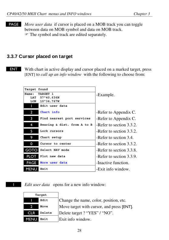
3.3.7 Cursor placed on target
ENT With chart in active display and cursor placed on a marked target, press[ENT] to call up an info window with the following to choose from:
Target found
Name: TARGET 1 LAT 57°40.636N LON 10°34.767W
-Example.
1 Edit user data
2 Chart info -Refer to Appendix C.
3 Find nearest port services -Refer to Appendix C.
4 Bearing & dist. from A to B -Refer to section 3.3.2.
5 Lock cursors -Refer to section 3.3.2.
9 Chart setup -Refer to section 3.4.0 Cursor to center -Refer to section 3.3.2.
GOTO Select NAV mode -Refer to section 3.3.8.
PLOT Plot new data -Refer to section 3.3.9.
PAGE More user data -Inactive function.
MENU Exit -Exit info window.
1 Edit user data opens for a new info window:
Target
1 Edit Change the name, color, position, etc.
2 Move Move target with cursor, and press [ENT].
CLR Delete Delete target ? “YES” / “NO”.
MENU Exit Exit info window.
CP40/42/50 MKII Chart menus and INFO windows Chapter 3
29
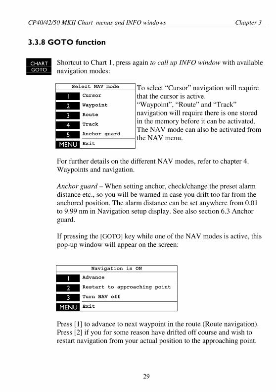
3.3.8 GOTO function
CHARTGOTO
Shortcut to Chart 1, press again to call up INFO window with availablenavigation modes:
Select NAV mode
1 Cursor
2 Waypoint
3 Route
4 Track
5 Anchor guard
MENU Exit
To select “Cursor” navigation will requirethat the cursor is active.“Waypoint”, “Route” and “Track”navigation will require there is one storedin the memory before it can be activated.The NAV mode can also be activated fromthe NAV menu.
For further details on the different NAV modes, refer to chapter 4.Waypoints and navigation.
Anchor guard – When setting anchor, check/change the preset alarmdistance etc., so you will be warned in case you drift too far from theanchored position. The alarm distance can be set anywhere from 0.01to 9.99 nm in Navigation setup display. See also section 6.3 Anchorguard.
If pressing the [GOTO] key while one of the NAV modes is active, thispop-up window will appear on the screen:
Navigation is ON
1 Advance
2 Restart to approaching point
3 Turn NAV off
MENU Exit
Press [1] to advance to next waypoint in the route (Route navigation).Press [2] if you for some reason have drifted off course and wish torestart navigation from your actual position to the approaching point.
CP40/42/50 MKII Chart menus and INFO windows Chapter 3
30
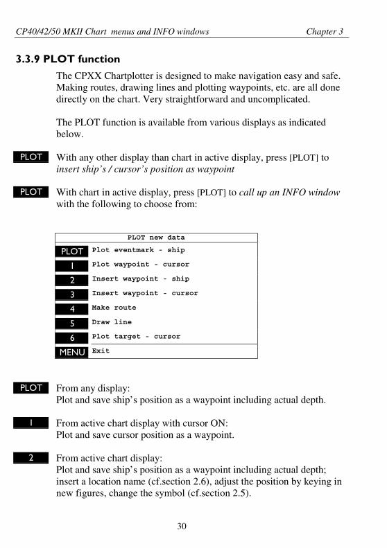
3.3.9 PLOT function
The CPXX Chartplotter is designed to make navigation easy and safe.Making routes, drawing lines and plotting waypoints, etc. are all donedirectly on the chart. Very straightforward and uncomplicated.
The PLOT function is available from various displays as indicatedbelow.
PLOT With any other display than chart in active display, press [PLOT] toinsert ship’s / cursor’s position as waypoint
PLOT With chart in active display, press [PLOT] to call up an INFO windowwith the following to choose from:
PLOT new data
PLOT Plot eventmark - ship
1 Plot waypoint - cursor
2 Insert waypoint - ship
3 Insert waypoint - cursor
4 Make route
5 Draw line
6 Plot target - cursor
MENU Exit
PLOT From any display:Plot and save ship’s position as a waypoint including actual depth.
1 From active chart display with cursor ON:Plot and save cursor position as a waypoint.
2 From active chart display:Plot and save ship’s position as a waypoint including actual depth;insert a location name (cf.section 2.6), adjust the position by keying innew figures, change the symbol (cf.section 2.5).
CP40/42/50 MKII Chart menus and INFO windows Chapter 3
31
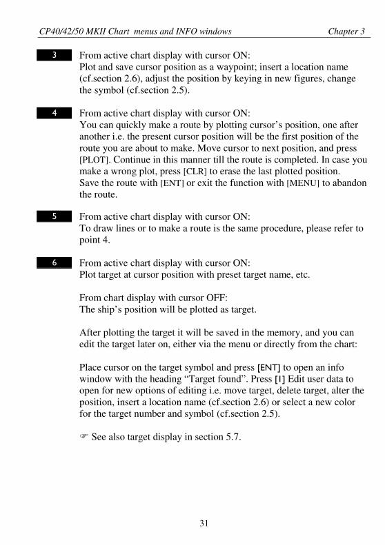
3 From active chart display with cursor ON:Plot and save cursor position as a waypoint; insert a location name(cf.section 2.6), adjust the position by keying in new figures, changethe symbol (cf.section 2.5).
4 From active chart display with cursor ON:You can quickly make a route by plotting cursor’s position, one afteranother i.e. the present cursor position will be the first position of theroute you are about to make. Move cursor to next position, and press[PLOT]. Continue in this manner till the route is completed. In case youmake a wrong plot, press [CLR] to erase the last plotted position.Save the route with [ENT] or exit the function with [MENU] to abandonthe route.
5 From active chart display with cursor ON:To draw lines or to make a route is the same procedure, please refer topoint 4.
6 From active chart display with cursor ON:Plot target at cursor position with preset target name, etc.
From chart display with cursor OFF:The ship’s position will be plotted as target.
After plotting the target it will be saved in the memory, and you canedit the target later on, either via the menu or directly from the chart:
Place cursor on the target symbol and press [ENT] to open an infowindow with the heading “Target found”. Press [1] Edit user data toopen for new options of editing i.e. move target, delete target, alter theposition, insert a location name (cf.section 2.6) or select a new colorfor the target number and symbol (cf.section 2.5).
See also target display in section 5.7.
CP40/42/50 MKII Chart menus and INFO windows Chapter 3
32
3.4 Chart setup
CHARTGOTO Hotkey to Chart 1
ENT
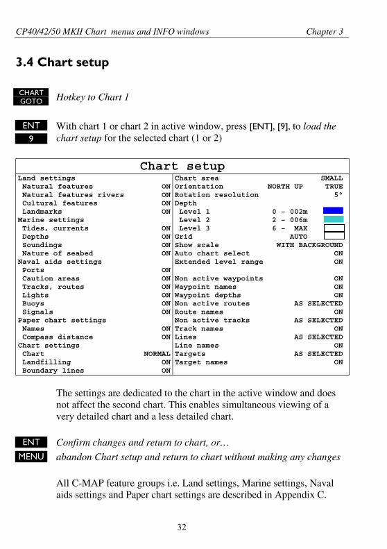
9With chart 1 or chart 2 in active window, press [ENT], [9], to load thechart setup for the selected chart (1 or 2)
Chart setupLand settings Natural features Natural features rivers Cultural features LandmarksMarine settings Tides, currents Depths Soundings Nature of seabedNaval aids settings Ports Caution areas Tracks, routes Lights Buoys SignalsPaper chart settings Names Compass distanceChart settings Chart Landfilling Boundary lines
ONONONON
ONONONON
ONONONONONON
ONON
NORMALONON
Chart area SMALLOrientation NORTH UP TRUERotation resolution 5°Depth Level 1 0 – 002m Level 2 2 – 006m Level 3 6 – MAXGrid AUTOShow scale WITH BACKGROUNDAuto chart select ONExtended level range ON
Non active waypoints ONWaypoint names ONWaypoint depths ONNon active routes AS SELECTEDRoute names ONNon active tracks AS SELECTEDTrack names ONLines AS SELECTEDLine names ONTargets AS SELECTEDTarget names ON
The settings are dedicated to the chart in the active window and doesnot affect the second chart. This enables simultaneous viewing of avery detailed chart and a less detailed chart.
ENT Confirm changes and return to chart, or…MENU abandon Chart setup and return to chart without making any changes
All C-MAP feature groups i.e. Land settings, Marine settings, Navalaids settings and Paper chart settings are described in Appendix C.
CP40/42/50 MKII Chart menus and INFO windows Chapter 3
33
All user data in the CPXX system are described below.
To obtain a “cleaner” view of the chart details, you can turn some ofthe settings OFF if they do not contribute to the clarity of the chart areayou wish to explore. All the listed objects that can be turned on and offspeaks for themselves – they are either “shown on the chart” or “notshown on the chart”.
Chart settings
Chart can be set to NORMAL, COMPRESSED and CHART OFF:NORMAL - will show the normal amount of details in the selected chartscale.COMPRESSED - will ordinarily provide more details in the same scale.CHART OFF - will only show all the user-made data such as waypoints,routes, lines and tracks, etc.
Landfilling can be ON or OFF. When OFF there will be no specialcolor to indicate where the land on the chart is (if any) i.e. land will beall blue.
Boundary lines will indicate available C-MAP chart areas.
Chart area can be set to LARGE, MEDIUM or SMALL:LARGE – Opens a large chart area for pan and scroll. Chart re-drawtime is standard.MEDIUM – Opens a medium-size chart area for pan and scroll.Chart re-draw time is faster than standard.SMALL – Opens a small chart area for pan scroll. Chart re-draw time isthe fastest.
Orientation can be set to NORTH UP, HEAD UP or NAV UP, and themode can be RELATIVE or TRUE motion.NORTH UP – The chart will always be presented as north up.HEAD UP – The chart will automatically turn, so your actual course(COG) is up. If a compass is connected, the reference will automatic-ally change to heading (compass).NAV UP – The chart will automatically turn, so your bearing to desti-nation is up.
To enable chart rotation, the chart cursor must be turned off [CLR].
CP40/42/50 MKII Chart menus and INFO windows Chapter 3
34
TRUE motion – The ‘ship’ will move across the chart.RELATIVE motion – (Chart area will default to MEDIUM). The ‘ship’ islocked to the center of the screen and the chart will move.
Rotation resolution can be set to adjust the chart for each 5, 10, 15, 20or 25° changes in present course or heading.
Depth – Level 1, 2 and 3 are identified by different colors. The numberof meters in the levels can be changed. The colors are preset in thePalette setup, section 7.2.6.
Grid the LAT/LON grid can be set AUTO/ON/OFF. The color of thegrid is preset in Palette setup, section 7.2.6.
Show scale ON will add a small line to the chart display indicating thatthe length of the line equals a certain number of nautical miles/km.
Auto chart select When sailing with “Auto chart select” ON and cursorturned OFF, the scale will automatically change to the chart which isavailable. But when set to OFF, then the selected scale will remain,also when sailing “out of the chart”.
Extended level range ON will provide a higher level of chart detailswhen zooming in and out of scales.
The rest of the objects in the chart setup, from Non active waypointsand down to the last line Target names can all be:ON = shown on chart orOFF = not shown on chart, orAS SELECTED = which means that the choice of having a certainroute shown on the display can be made via the menu e.g. [MENU], [3]WP/RTE, [2] Routes and [ENT] – where Course line can be set ON orOFF.
CP40/42/50 MKII Position menus Chapter 4
35
4. Position menu
_2_
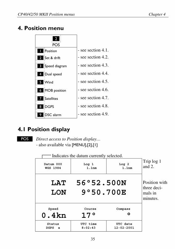
POS_1_ Position - see section 4.1.
_2_ Set & drift - see section 4.2.
_3_ Speed diagram - see section 4.3.
_4_ Dual speed - see section 4.4.
_5_ Wind - see section 4.5.
_6_ MOB position - see section 4.6.
_7_ Satellites - see section 4.7.
_8_ DGPS - see section 4.8.
_9_ DSC alarm - see section 4.9.
4.1 Position display
POS Direct access to Position display…- also available via [MENU],[2],[1]
Indicates the datum currently selected.
Datum 000WGS 1984
Log 1 1.1nm
Log 2 1.1nm
LAT 56°52.500NLON 9°50.700E
Speed Course Compass
0.4kn 17° °StatusDGPS a
UTC time8:02:43
UTC date12-02-2001
Trip log 1and 2.
Position withthree deci-mals inminutes.
CP40/42/50 MKII Position menus Chapter 4
36
Speed indicates Speed over ground.
Course, magnetic or true.
Depth or Compass from external sensor.
UTC or local time and dateTime and date in UTC – Universal Time Coordinates – is equal tostandard time in London (GMT). UTC is not affected by the localsummertime adjustments.
Status indicator for reception of satellites:a(A)= good, b(B)= acceptable, c(C)= fair, or *= no update - see also“Status indicator and accuracy” below.
With DGPS receiver built-in or connected:dGPS= differential data received.DGPS= corrected differential data received.
Status indicator and accuracySmall letters (a,b,c,) indicate that SA is active, and the positionaccuracy is expected to be better than 100 meters in 95% of the time.Capital letters indicate that SA is OFF, and the position accuracy isthen expected to be 15 meters or better in 95% of the time.dGPS indicates that differential data is received, either via built-indifferential receiver or from external receiver.And DGPS indicates that the position is corrected by the differentialdata. The accuracy will typically be 3-5 meters.
In order to utilize the high accuracy of the GPS system, it is necessaryto align the lat/long calculations to the paper charts you are using.Refer to Position setup display on next page.
When using C-MAP electronic charts, the datum will be alignedautomatically.
CP40/42/50 MKII Position menus Chapter 4
37
Position setup
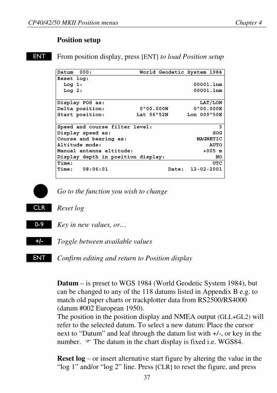
ENT From position display, press [ENT] to load Position setup
Datum 000: World Geodetic System 1984Reset log: Log 1: 00001.1nm Log 2: 00001.1nm
Display POS as: LAT/LONDelta position: 0°00.000N 0°00.000EStart position: Lat 56°52N Lon 009°50E
Speed and course filter level: 3Display speed as: SOGCourse and bearing as: MAGNETICAltitude mode: AUTOManual antenna altitude: +005 mDisplay depth in position display: NOTime: UTCTime: 08:06:01 Date: 12-02-2001
Go to the function you wish to change
CLR Reset log
0-9 Key in new values, or…
+/- Toggle between available values
ENT Confirm editing and return to Position display
Datum – is preset to WGS 1984 (World Geodetic System 1984), butcan be changed to any of the 118 datums listed in Appendix B e.g. tomatch old paper charts or trackplotter data from RS2500/RS4000(datum #002 European 1950).The position in the position display and NMEA output (GLL+GL2) willrefer to the selected datum. To select a new datum: Place the cursornext to “Datum” and leaf through the datum list with +/-, or key in thenumber. The datum in the chart display is fixed i.e. WGS84.
Reset log – or insert alternative start figure by altering the value in the“log 1” and/or “log 2” line. Press [CLR] to reset the figure, and press
CP40/42/50 MKII Position menus Chapter 4
38
the numeric keys 0-9 to alter the figure.
Display position as – the position can be shown in latitude/longitude,Loran C or decca coordinates (after selecting chain). Toggle with +/-.
Delta position – some paper charts do not indicate a datum, but insteadthey have a notation to an offset or delta position to WGS84.Use numeric keys to key in the position correction.
Start position – can be inserted if exact start position is known.
Speed and course filter level – there is a filter of 10 steps available(0= fast response, 9= stable readout).
Display speed as – SOG Speed Over Ground or STW Speed ThroughWater. Toggle with +/-.
to receive STW information from external instrument (via NMEAport) will require that NMEA sentence VHW and “Log speed sensor”are set to ON in. Refer to section 7.2.1 and 7.2.2.
Course and bearing – readings of course and bearing can be made ineither MAGNETIC or TRUE. Toggle with +/-.
Altitude mode – is preset to automatic, but can be changed to manual.Toggle with +/-.
Manual antenna altitude – is preset to 5m. Insert actual antennaheight if manual altitude mode is selected. This value will not beshown anywhere else, but will be used for computations.
Display depth in position display – if set to YES, then the depth willbe shown when NMEA depth data is received from connected depthinstrument.When set to NO, then “Compass” from connected sensor (compass)will be shown instead.
Time – can be set to UTC or local. Toggle with +/-.Correct actual time and date by means of the numeric keys.
CP40/42/50 MKII Position menus Chapter 4
39
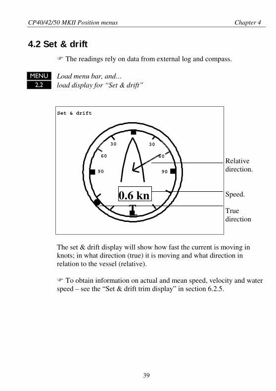
4.2 Set & drift
The readings rely on data from external log and compass.
MENU Load menu bar, and…2,2 load display for “Set & drift”
Set & drift
0.6 knT
Relativedirection.
Speed.
Truedirection
The set & drift display will show how fast the current is moving inknots; in what direction (true) it is moving and what direction inrelation to the vessel (relative).
To obtain information on actual and mean speed, velocity and waterspeed – see the “Set & drift trim display” in section 6.2.5.
30
60
90
30
60
90
CP40/42/50 MKII Position menus Chapter 4
40
S 6.2kn V 4.8kn W 2.2kn
[kn] 13:49 14:04 14:19 10
8
6
4
2
0
SD: S *.*kn T***° R***° WIND:*.*ms ***°R
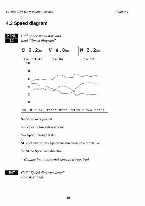
4.3 Speed diagram
MENU Call up the menu bar, and…2,3 load “Speed diagram”
S= Speed over ground.
V= Velocity towards waypoint.
W= Speed through water.
SD (Set and drift)*= Speed and direction, true or relative.
WIND*= Speed and direction.
* Connection to external sensors is required.
ENT Call “Speed diagram setup”- see next page
CP40/42/50 MKII Position menus Chapter 4
41
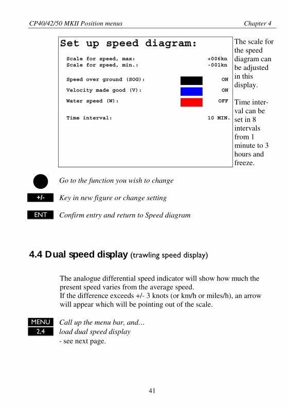
Set up speed diagram: Scale for speed, max: +006kn Scale for speed, min.: -001kn
Speed over ground (SOG): ON
Velocity made good (V): ON
Water speed (W): OFF
Time interval: 10 MIN.
The scale forthe speeddiagram canbe adjustedin thisdisplay.
Time inter-val can beset in 8intervalsfrom 1minute to 3hours andfreeze.
Go to the function you wish to change
+/- Key in new figure or change setting
ENT Confirm entry and return to Speed diagram
4.4 Dual speed display (trawling speed display)
The analogue differential speed indicator will show how much thepresent speed varies from the average speed.If the difference exceeds +/- 3 knots (or km/h or miles/h), an arrowwill appear which will be pointing out of the scale.
MENU Call up the menu bar, and…2,4 load dual speed display
- see next page.
CP40/42/50 MKII Position menus Chapter 4
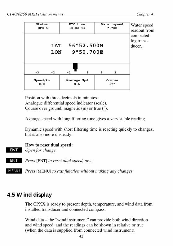
42
Status GPS a
UTC time10:02:43
Water speed*.*kn
LAT 56°52.500NLON 9°50.700E
-3 -2 -1 1 2 3
Speed/kn0.8
Average Spd0.6
Course17°
Water speedreadout fromconnectedlog trans-ducer.
Position with three decimals in minutes.Analogue differential speed indicator (scale).Course over ground, magnetic (m) or true (°).
Average speed with long filtering time gives a very stable reading.
Dynamic speed with short filtering time is reacting quickly to changes,but is also more unsteady.
How to reset dual speed:ENT Open for change
ENT Press [ENT] to reset dual speed, or…
MENU Press [MENU] to exit function without making any changes
4.5 Wind display
The CPXX is ready to present depth, temperature, and wind data frominstalled transducer and connected compass.
Wind data – the “wind instrument” can provide both wind directionand wind speed, and the readings can be shown in relative or true(when the data is supplied from connected wind instrument).
CP40/42/50 MKII Position menus Chapter 4
43
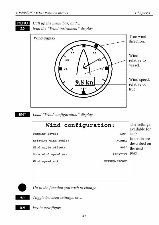
Wind display
9.8 knT
MENU Call up the menu bar, and…2,5 load the “Wind instrument” display
ENT Load “Wind configuration” display
Wind configuration:Damping level: LOW
Relative wind scale: NORMAL
Wind angle offset: 000°
Show wind speed as: RELATIVE
Wind speed unit: METERS/SECOND
The settingsavailable foreachfunction aredescribed onthe nextpage.
Go to the function you wish to change
+/- Toggle between settings, or…
0-9 key in new figure
True winddirection.
Windrelative tovessel.
Wind speed,relative ortrue.
30
60
90
30
60
90
CP40/42/50 MKII Position menus Chapter 4
44
ENT Confirm entry and return to Wind display
Damping level – can be set to LOW, MEDIUM or HIGH. The higherlevel the more steady and slow reacting reading.
Relative wind scale – can either be set to NORMAL (0-180°) orMAGNIFIED (0-60°).
Wind angle offset – can be from 0 to 360°.
Show wind speed as – TRUE or RELATIVE.
Wind speed unit – can be either METERS/SECOND, KNOTS,KILOMETERS/HOUR or MILES/HOUR.
4.6 MOB position
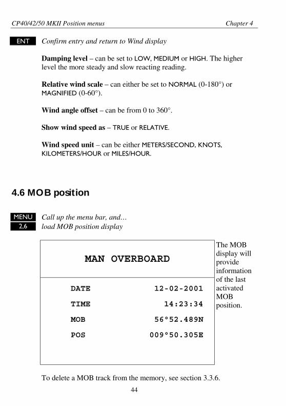
MENU Call up the menu bar, and…2,6 load MOB position display
MAN OVERBOARD
DATE 12-02-2001
TIME 14:23:34
MOB 56°52.489N
POS 009°50.305E
The MOBdisplay willprovideinformationof the lastactivatedMOBposition.
To delete a MOB track from the memory, see section 3.3.6.
CP40/42/50 MKII Position menus Chapter 4
45
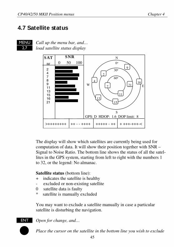
4.7 Satellite status
MENU Call up the menu bar, and…2,7 load satellite status display
The display will show which satellites are currently being used forcomputation of data. It will show their position together with SNR –Signal to Noise Ratio. The bottom line shows the status of all the satel-lites in the GPS system, starting from left to right with the numbers 1to 32, or the legend: No almanac.
Satellite status (bottom line):+ indicates the satellite is healthy- excluded or non-existing satellite0 satellite data is faulty* satellite is manually excluded
You may want to exclude a satellite manually in case a particularsatellite is disturbing the navigation.
ENT Open for change, and…
Place the cursor on the satellite in the bottom line you wish to exclude
GPS: D HDOP: 1.6 DOP limit: 8
SATnr
>++++++++ ++ - - ++++ +++++ - ++ + +++-+++-<
247891113151621
60°
30°
W E
SNR0 50 100
S
0°
N
7
2
4
9
1113
15
1621
CP40/42/50 MKII Position menus Chapter 4
46
��������������
���� ������
����������
�� ����
������
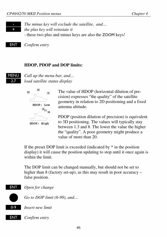
HDOP: High
HDOP: Low
- The minus key will exclude the satellite, and…+ the plus key will reinstate it
- these two plus and minus keys are also the ZOOM keys!
ENT Confirm entry
HDOP, PDOP and DOP limits:
MENU Call up the menu bar, and…2,7 load satellite status display
The value of HDOP (horizontal dilution of pre-cision) expresses “the quality” of the satellitegeometry in relation to 2D positioning and a fixedantenna altitude.
PDOP (position dilution of precision) is equivalentto 3D positioning. The values will typically staybetween 1.3 and 8. The lower the value the higherthe “quality”. A poor geometry might produce avalue of more than 20.
If the preset DOP limit is exceeded (indicated by * in the positiondisplay) it will cause the position updating to stop until it once again iswithin the limit.
The DOP limit can be changed manually, but should not be set tohigher than 8 (factory set-up), as this may result in poor accuracy –false position.
ENT Open for change
Go to DOP limit (6-99), and…
0-9 Insert new limit
ENT Confirm entry
CP40/42/50 MKII Position menus Chapter 4
47
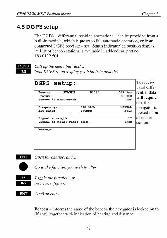
4.8 DGPS setup
The DGPS – differential position corrections – can be provided from abuilt-in module, which is preset to full automatic operation, or fromconnected DGPS receiver – see ‘Status indicator’ in position display.
List of beacon stations is available in addendum, part no.183.0122.501.
MENU Call up the menu bar, and…2,8 load DGPS setup display (with built-in module)
DGPS setup:
Beacon: SKAGEN B312° D87.3nm Status: LOCKED Beacon is monitored: YES
Frequency: 298.5kHz MANUAL Bit rate: 100bps AUTO
Signal strength: 17 Signal to noise ratio (SNR): 23dB
Message:
To receivevalid diffe-rential datawill requirethat thenavigator islocked in ona beaconstation.
ENT Open for change, and…
Go to the function you wish to alter
+/- Toggle the function, or…0-9 insert new figures
ENT Confirm entry
Beacon – informs the name of the beacon the navigator is locked on to(if any), together with indication of bearing and distance.
CP40/42/50 MKII Position menus Chapter 4
48
Status – can either be:LOCKED = locked on a beacon and receiving differential data.NOT LOCKED = not locked on a beacon and receiving no differentialdata.NOT INSTALLED = there is no built-in DGPS module in unit.NOT IN USE = external DGPS receiver applied.
Beacon is monitored – YES or NO.If YES it should be safe to rely on the received differential data,because the beacon station’s performance is under observation.If NO, then you have to use the received differential data with caution,as there is no guarantee it is not faulty.
Frequency – the frequency of the beacon station can be set manually ifknown. However, when left in AUTO the navigator will always searchfor the nearest station with a good signal strength.
Bit rate – indicates bits per second, and can be set manually to 25, 50,100 or 200 bps.
Signal strength – a good signal strength is 20 and up.
Signal to noise ratio (SNR) – should be 8dB and up.
Message – type 16 message will be displayed when received from theDGPS system. The contents of this message could be something to dowith the performance of the system. Temporarily out of service, etc.
CP40/42/50 MKII Position menus Chapter 4
49
4.9 DSC alarm (feature prepared for future DSC VHF)
To receive a DSC Alarm and Message from VHF will require thatthe chartplotter is connected to a compatible Simrad Shipmate VHFradiotelephone, which is expected to be launched in the beginning ofyear 2001.
The message from the VHF will appear in a pop-up window togetherwith an acoustic alarm. Press [CLR] to reset the alarm.
To view the last received message:
MENU Call up the menu bar, and…2,9 press [2] and [9] to call up the message display

CP40/42/50 MKII Position menus Chapter 4
50
CP40/42/50 MKII Waypoint/route menus Chapter 5
51
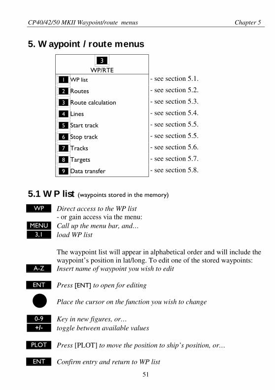
5. Waypoint / route menus
_3_
WP/RTE_1_ WP list - see section 5.1.
_2_ Routes - see section 5.2.
_3_ Route calculation - see section 5.3.
_4_ Lines - see section 5.4.
_5_ Start track - see section 5.5.
_6_ Stop track - see section 5.5.
_7_ Tracks - see section 5.6.
_8_ Targets - see section 5.7.
_9_ Data transfer - see section 5.8.
5.1 WP list (waypoints stored in the memory)
WP Direct access to the WP list- or gain access via the menu:
MENU Call up the menu bar, and…3,1 load WP list
The waypoint list will appear in alphabetical order and will include thewaypoint’s position in lat/long. To edit one of the stored waypoints:
A-Z Insert name of waypoint you wish to edit
ENT Press [ENT] to open for editing
Place the cursor on the function you wish to change
0-9 Key in new figures, or…+/- toggle between available values
PLOT Press [PLOT] to move the position to ship’s position, or…
ENT Confirm entry and return to WP list

CP40/42/50 MKII Waypoint/route menus Chapter 5
52
Plot new waypoints with the [PLOT] key. Refer to section 3.3.9.
5.1.1 Delete waypoints via menu
WP Hotkey to WP list
+/- Select waypoint you wish to delete
ENT Press [ENT] to open for editing
WIN Press [WIN] to delete waypoint
CLR Confirm entry and return to WP list
Edit waypoints directly on the chart via info windows. Refer tosection 3.3.3.
5.2 Routes stored in the memory
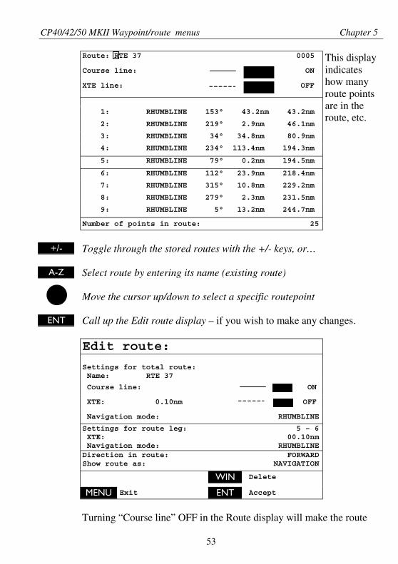
The route list will keep a record of all the saved routes in the system.It will provide information on number of waypoints in the route, etc.
To make new routes you need a chart in the active window, placethe cursor where you wish to place the first routepoint, and press[PLOT]. Then follow the instructions in the info windows. Refer tosection 3.3.9.
To delete a route, refer to section 5.2.1.
Routes can also be edited directly on the chart via info windows. Referto section 3.3.4 and 3.3.5.
ROUTE Direct access to the Route list- or gain access via the menu:
MENU Call up the menu bar, and…3,2 load route display - see example next page.
CP40/42/50 MKII Waypoint/route menus Chapter 5
53
Route: RTE 37 0005
Course line: ON
XTE line: OFF
1: RHUMBLINE 153° 43.2nm 43.2nm
2: RHUMBLINE 219° 2.9nm 46.1nm
3: RHUMBLINE 34° 34.8nm 80.9nm
4: RHUMBLINE 234° 113.4nm 194.3nm
5: RHUMBLINE 79° 0.2nm 194.5nm
6: RHUMBLINE 112° 23.9nm 218.4nm
7: RHUMBLINE 315° 10.8nm 229.2nm
8: RHUMBLINE 279° 2.3nm 231.5nm
9: RHUMBLINE 5° 13.2nm 244.7nm
Number of points in route: 25
This displayindicateshow manyroute pointsare in theroute, etc.
+/- Toggle through the stored routes with the +/- keys, or…
A-Z Select route by entering its name (existing route)
Move the cursor up/down to select a specific routepoint
ENT Call up the Edit route display – if you wish to make any changes.
Edit route:
Settings for total route: Name: RTE 37
Course line: ON
XTE: 0.10nm OFF
Navigation mode: RHUMBLINE
Settings for route leg: 5 – 6 XTE: 00.10nm Navigation mode: RHUMBLINEDirection in route: FORWARDShow route as: NAVIGATION
WIN Delete
MENU Exit ENT Accept
Turning “Course line” OFF in the Route display will make the route
CP40/42/50 MKII Waypoint/route menus Chapter 5
54
invisible on the screen. Put it back on the screen by turning it ONagain. The course line and XTE line can be changed in color – thereare a total of 14 colors to choose from, and 9 different line types.
If the XTE distance is not the same in all legs, the value will be *.*instead of the 0.10nm. Navigation mode can be either Rhumbline orGreat circle, or … if not the same in all legs in a route, the mode willbe: COMPOSITE.
Show route as: NAVIGATION for navigational data in the route display(example on the previous page), or POINTS for a list of route pointstogether with the points’ position in lat/lon and the XTE limit.
Place the cursor on the function you wish to change
0-9 Key in new figures, and…+/- toggle between available values
ENT Confirm entry
5.2.1 Delete route via menu
ROUTE Hotkey to Route list
+/- Select the route you wish to delete
ENT Press [ENT] to open for editing
WIN Press [WIN] to delete route
CLR Confirm
Edit routes directly on the chart via info windows. Refer to section3.3.4 and 3.3.5.
CP40/42/50 MKII Waypoint/route menus Chapter 5
55
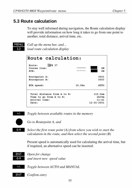
5.3 Route calculation
To stay well informed during navigation, the Route calculation displaywill provide information on how long it takes to go from one point toanother, total distance, arrival time, etc.
MENU Call up the menu bar, and…3,3 load route calculation display
Route calculation: Route: RTE 37 Course line: ON XTE: ON
Routepoint A: 0001 Routepoint B: 0003
ETA speed: 10.0kn AUTO
Total distance from A to B: 110.5nm Time to go from A to B: 2h35m Arrival time: 11:41 Date: 12-02-2001
+/- Toggle between available routes in the memory
Go to Routepoint A, and
0-9 Select the first route point (A) from where you wish to start thecalculation in the route, and then select the second point (B)
Present speed is automatically used for calculating the arrival time, butif required, an alternative speed can be inserted:
ENT Open for change0-9 and insert new speed value
+/- Toggle between AUTO and MANUAL
ENT Confirm entry
CP40/42/50 MKII Waypoint/route menus Chapter 5
56
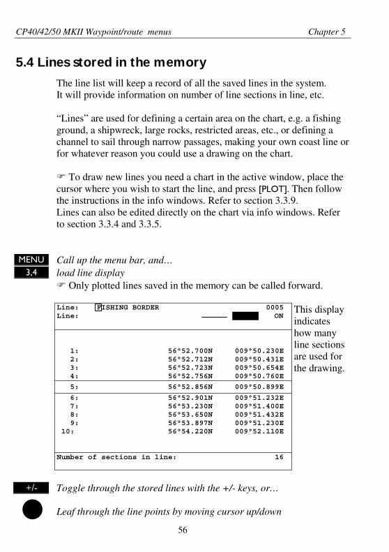
5.4 Lines stored in the memory
The line list will keep a record of all the saved lines in the system.It will provide information on number of line sections in line, etc.
“Lines” are used for defining a certain area on the chart, e.g. a fishingground, a shipwreck, large rocks, restricted areas, etc., or defining achannel to sail through narrow passages, making your own coast line orfor whatever reason you could use a drawing on the chart.
To draw new lines you need a chart in the active window, place thecursor where you wish to start the line, and press [PLOT]. Then followthe instructions in the info windows. Refer to section 3.3.9.Lines can also be edited directly on the chart via info windows. Referto section 3.3.4 and 3.3.5.
MENU Call up the menu bar, and…3,4 load line display
Only plotted lines saved in the memory can be called forward.
Line: FISHING BORDER 0005Line: ON
1: 56°52.700N 009°50.230E 2: 56°52.712N 009°50.431E 3: 56°52.723N 009°50.654E 4: 56°52.756N 009°50.760E
5: 56°52.856N 009°50.899E
6: 56°52.901N 009°51.232E 7: 56°53.230N 009°51.400E 8: 56°53.650N 009°51.432E 9: 56°53.897N 009°51.230E 10: 56°54.220N 009°52.110E
Number of sections in line: 16
This displayindicateshow manyline sectionsare used forthe drawing.
+/- Toggle through the stored lines with the +/- keys, or…
Leaf through the line points by moving cursor up/down
CP40/42/50 MKII Waypoint/route menus Chapter 5
57
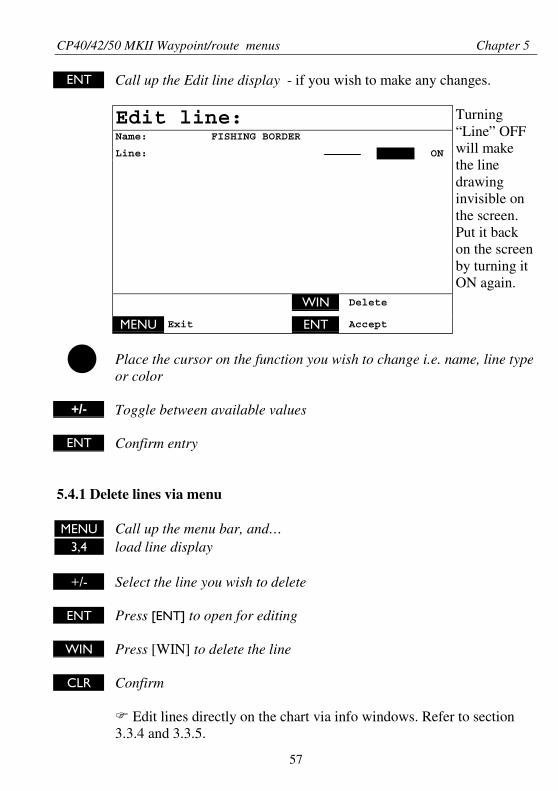
ENT Call up the Edit line display - if you wish to make any changes.
Edit line:Name: FISHING BORDER
Line: ON
Turning“Line” OFFwill makethe linedrawinginvisible onthe screen.Put it backon the screenby turning itON again.
WIN Delete
MENU Exit ENT Accept
Place the cursor on the function you wish to change i.e. name, line typeor color
+/- Toggle between available values
ENT Confirm entry
5.4.1 Delete lines via menu
MENU Call up the menu bar, and…3,4 load line display
+/- Select the line you wish to delete
ENT Press [ENT] to open for editing
WIN Press [WIN] to delete the line
CLR Confirm
Edit lines directly on the chart via info windows. Refer to section3.3.4 and 3.3.5.
CP40/42/50 MKII Waypoint/route menus Chapter 5
58
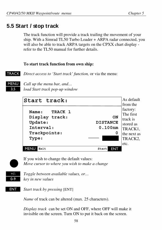
5.5 Start / stop track
The track function will provide a track trailing the movement of yourship. With a Simrad TL50 Turbo Loader + ARPA radar connected, youwill also be able to track ARPA targets on the CPXX chart display -refer to the TL50 manual for further details.
To start track function from own ship:
TRACK Direct access to ‘Start track’ function, or via the menu:
MENU Call up the menu bar, and…3,5 load Start track pop-up window
Start track:
Name: TRACK 1 Display track: ON Update: DISTANCE Interval: 0.100nm Trackpoints: 0 Type:
As defaultfrom thefactory:The firsttrack isstored asTRACK1,the next asTRACK2,etc.
MENU Exit Start ENT
If you wish to change the default values:Move cursor to where you wish to make a change
+/- Toggle between available values, or…0-9 key in new values
ENT Start track by pressing [ENT]
Name of track can be altered (max. 25 characters).
Display track can be set ON and OFF, where OFF will make itinvisible on the screen. Turn ON to put it back on the screen.
CP40/42/50 MKII Waypoint/route menus Chapter 5
59
Update of the track can be performed by distance in nautical miles, orby time interval.
Type of track line i.e. full, dotted, etc. has 9 different types to choosefrom in 15 different colors.
To stop track:MENU Call up the menu bar, and…
3,6 load Stop track pop-up window
ENT Press [ENT] to stop the highlighted track
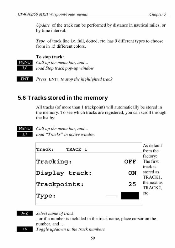
5.6 Tracks stored in the memory
All tracks (of more than 1 trackpoint) will automatically be stored inthe memory. To see which tracks are registered, you can scroll throughthe list by:
MENU Call up the menu bar, and…3,7 load “Tracks” in active window
Track: TRACK 1
Tracking: OFF
Display track: ON
Trackpoints: 25
Type:
As defaultfrom thefactory:The firsttrack isstored asTRACK1,the next asTRACK2,etc.
A-Z Select name of track- or if a number is included in the track name, place cursor on thenumber, and …
+/- Toggle up/down in the track numbers
CP40/42/50 MKII Waypoint/route menus Chapter 5
60
ENT Open for change
“Display track” can be set ON/OFF, where OFF will make it invisibleon the screen. Turn ON to put it back on the screen.
+/- Toggle between available values
ENT Confirm changes
5.6.1 Delete tracks via menu
MENU Call up the menu bar, and…3,7 load track display
+/- Select the track you wish to delete
ENT Press [ENT] to open for editing
WIN Press [WIN] to delete the track
CLR Confirm
Edit tracks directly on the chart via info windows. Refer to section3.3.6.
5.7 Targets stored in the memory
The CPXX can display the bearing and distance of up to three targetsat a time in relation to the vessel e.g. harbors or important navigationalpoints. A target is a fixed point on the chart which can be plotted by thecursor or from the ship’s position, or keyed in via the keypad.
Set up targetsThe plotted target position is automatically preset to actual position ofship, or to cursor position when the chart display is active and thecursor is on – see INFO windows, section 3.3.7.
CP40/42/50 MKII Waypoint/route menus Chapter 5
61
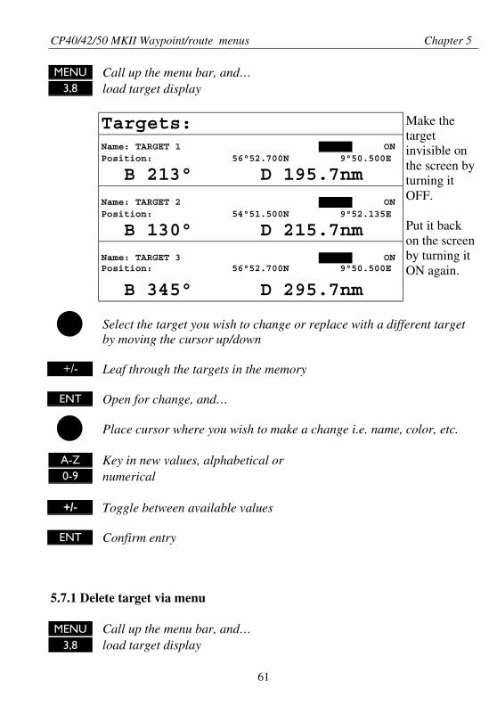
MENU Call up the menu bar, and…3,8 load target display
Targets:Name: TARGET 1 ONPosition: 56°52.700N 9°50.500E
B 213° D 195.7nm
Name: TARGET 2 ONPosition: 54°51.500N 9°52.135E
B 130° D 215.7nm
Name: TARGET 3 ONPosition: 56°52.700N 9°50.500E
B 345° D 295.7nm
Make thetargetinvisible onthe screen byturning itOFF.
Put it backon the screenby turning itON again.
Select the target you wish to change or replace with a different targetby moving the cursor up/down
+/- Leaf through the targets in the memory
ENT Open for change, and…
Place cursor where you wish to make a change i.e. name, color, etc.
A-Z Key in new values, alphabetical or0-9 numerical
+/- Toggle between available values
ENT Confirm entry
5.7.1 Delete target via menu
MENU Call up the menu bar, and…3,8 load target display
CP40/42/50 MKII Waypoint/route menus Chapter 5
62
+/- Select the target you wish to delete
ENT Press [ENT] to open for editing
WIN Press [WIN] to delete the target
CLR Confirm
Edit targets directly on the chart via info windows. Refer to section3.3.7.
5.8 Data transfer via DataCard or disc
Data transfer to and from external memory can be performed via Data-Card, or with a Simrad TL50 Turbo Loader: via an ordinary 1.44Mbdisc.
DataCards and TL50 Turbo Loader are optional equipment availablefrom you local Simrad dealer.How to perform data transfers via TL50 Turbo Loader (inclusive datafrom Shipmate RS2500 Trackplotter) is described in the TL50 manual.
Use the Simrad DataCard or TL50 Turbo Loader to make backup filesof all the user data you have created plus the current setups in theinternal memory of the unit. Do it whenever you have added importantdata, or when you wish to transfer routes and waypoints, etc. to anothercompatible unit.The storage capacity of the DataCard/TL50 disc is divided into twodatabanks of each 450 Kb, meaning that the entire internal memory canbe stored in one databank.
• External memory with data transfer via DataCard:
MENU Call up the menu bar, and…3,9 load the ‘Data transfer’ window
Select the drawer where you have inserted the DataCard i.e. [1] for the
CP40/42/50 MKII Waypoint/route menus Chapter 5
63
upper drawer, and [3] for the lower drawer.
You now have a choice of:[1] DataCard status[3] Save on DataCard[9] Load from DataCard
DataCard status1 Press [1] to find out what data (if any) is stored on the DataCard
The capacity is divided into two databanks: DATABANK 1 and 2which can hold approx. 2 x 450 Kb data. Toggle between the twodatabanks with the +/- zoom keys.
Save on DataCard3 Press [3] to call up a new INFO window where you can see which data
will be transferred i.e. how many routes, waypoints, etc. and how muchspace it will take up in bytes + percentage of max. storage capacity.Choose which databank you wish to transfer the data to (use the +/-zoom keys).The actual date and time will be saved with the data transfer.A name can be added for easy identification later on.
ENT Press [ENT] to activate ‘Save on DataCard’
You will now receive a warning that existing data on the DataCard,in the databank you have chosen, will be overwritten. You can not ‘addmore information’ to data already transferred. Whenever transferringdata either from an XX40/42/50 MKII to Databank 1 or 2 on DataCard,or from Databank 1 or 2 on DataCard to an XX40/42/50 MKII, the datapackage will replace the entire capacity in the receiving unit, exceptwhen a TL50 Turbo Loader is connected to the unit, then you candecide how much data you want to transfer - refer to TL50 manual
Load from DataCard9 Press [9] to call up a new INFO window where you can see which data
is stored in Databank 1 or 2 on the DataCard - see example of displayon next page, without TL50 connected.
CP40/42/50 MKII Waypoint/route menus Chapter 5
64
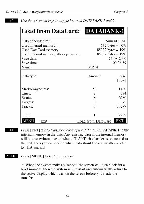
+/- Use the +/- zoom keys to toggle between DATABANK 1 and 2
Load from DataCard: DATABANK-1
Data generated by: Simrad CP40Used internal memory: 672 bytes = 0%Used DataCard memory: 85332 bytes = 19%Used internal memory after operation: 85332 bytes = 19%Save date: 24-08-2000Save time: 09:26:59Name: MR14
Data type Amount Size
Marks/waypoints: 52
[byte]
1120Lines: 2 284Routes: 8 6280Targets: 3 72Tracks: 5 75287
Setup: 1 2289
Exit Load from DataCard
ENT Press [ENT] x 2 to transfer a copy of the data in DATABANK 1 to theinternal memory in the unit. Any existing data in the internal memorywill be overwritten, except when a TL50 Turbo Loader is connected tothe unit, then you can decide which data should be overwritten - referto TL50 manual
MENU Press [MENU] to Exit, and reboot
When the system makes a ‘reboot’ the screen will turn black for abrief moment, then the system will re-start and automatically return tothe active display which was on the screen before you made thetransfer.
MENU ENT
CP40/42/50 MKII NAV menus & navigation examples Chapter 6
65
6.1 NAV menu – (NAV inactive)
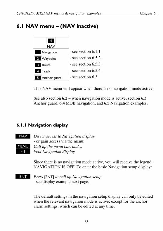
_4_
NAV_1_ Navigation - see section 6.1.1.
_2_ Waypoint - see section 6.5.2.
_3_ Route - see section 6.5.3.
_4_ Track - see section 6.5.4.
_5_ Anchor guard - see section 6.3.
This NAV menu will appear when there is no navigation mode active.
See also section 6.2 – when navigation mode is active, section 6.3Anchor guard, 6.4 MOB navigation, and 6.5 Navigation examples.
6.1.1 Navigation display
NAV Direct access to Navigation display- or gain access via the menu:
MENU Call up the menu bar, and…4,1 load Navigation display
Since there is no navigation mode active, you will receive the legend:NAVIGATION IS OFF. To enter the basic Navigation setup display:
ENT Press [ENT] to call up Navigation setup- see display example next page.
The default settings in the navigation setup display can only be editedwhen the relevant navigation mode is active; except for the anchoralarm settings, which can be edited at any time.
CP40/42/50 MKII NAV menus & navigation examples Chapter 6
66
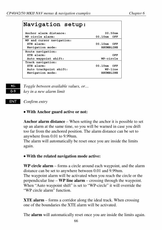
Navigation setup: Anchor alarm distance: 00.50nm WP circle alarm: 00.10nm OFF WP and cursor navigation: XTE alarm: 00.10nm OFF Navigation mode: RHUMBLINE
Route navigation: XTE alarm: OFF Auto waypoint shift: WP-circle Track navigation: XTE alarm: 00.10nm OFF Auto trackpoint shift: WP-line Navigation mode: RHUMBLINE
+/- Toggle between available values, or…0-9 key in a new alarm limit
ENT Confirm entry
•••• With Anchor guard active or not:
Anchor alarm distance – When setting the anchor it is possible to setup an alarm at the same time, so you will be warned in case you drifttoo far from the anchored position. The alarm distance can be set toanywhere from 0.01 to 9.99nm.The alarm will automatically be reset once you are inside the limitsagain.
•••• With the related navigation mode active:
WP circle alarm – forms a circle around each waypoint, and the alarmdistance can be set to anywhere between 0.01 and 9.99nm.The waypoint alarm will be activated when you reach the circle or theperpendicular line – WP line alarm – crossing through the waypoint.When “Auto waypoint shift” is set to “WP-circle” it will override the“WP circle alarm” function.
XTE alarm – forms a corridor along the ideal track. When crossingone of the boundaries the XTE alarm will be activated.
The alarm will automatically reset once you are inside the limits again.
CP40/42/50 MKII NAV menus & navigation examples Chapter 6
67
The alarm distance can be set to anywhere between 0.01 and 9.99nm.In Route navigation the XTE alarm value can be specified for each
route leg – see section 5.2.
Navigation mode – RHUMBLINE navigation is used for shorterdistances, and GREAT CIRCLE for long trips, especially when crossingat high latitudes. COMPOSITE navigation is used when not all legs in aroute are set to the same navigation mode.
Auto waypoint shift – can be set to “WP-circle”, “WP-line” or “OFF”.When set to WP-circle, the system will change to the next waypoint inthe route after passing the circle line (border).When set to WP-line, the system will change to next waypoint in theroute after passing the waypoint line (border).When “Auto waypoint shift” is set to “WP-circle”, then the alarmfunction at the waypoint’s circle will not be activated.
6.2 NAV menu – (NAV active)
_4_
NAV_1_ Navigation - see section 6.2.1.
_2_ Turn NAV off - see section 6.2.3.
_3_ ETA & AVN - see section 6.2.4.
_4_ Set & drift trim - see section 6.2.5.
_5_ WP advance - see section 6.2.6.
This NAV menu will appear when navigation mode is active.If the selected navigation mode is Waypoint navigation, then point5:Waypoint advance will not be available and therefore the color of thetext will differ from the rest of the menu text.
See also section 6.1 NAV menu – (NAV inactive), section 6.3 Anchorguard, 6.4 MOB navigation, and 6.5 Navigation examples.
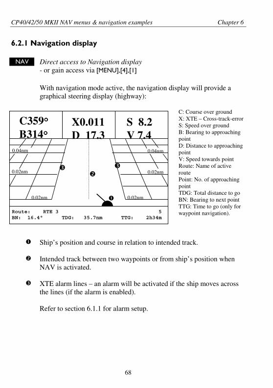
CP40/42/50 MKII NAV menus & navigation examples Chapter 6
68
Route: RTE 3 5BN: 16.4° TDG: 35.7nm TTG: 2h34m
S 8.2V 7.4
C359°°°°B314°°°°
X0.011D 17.3
0.04nm
0.02nm
0.02nm
0.04nm
0.02nm
0.02nm
6.2.1 Navigation display
NAV Direct access to Navigation display- or gain access via [MENU],[4],[1]
With navigation mode active, the navigation display will provide agraphical steering display (highway):
C: Course over groundX: XTE – Cross-track-errorS: Speed over groundB: Bearing to approachingpointD: Distance to approachingpointV: Speed towards pointRoute: Name of activeroutePoint: No. of approachingpointTDG: Total distance to goBN: Bearing to next pointTTG: Time to go (only forwaypoint navigation).
Ship’s position and course in relation to intended track.
Intended track between two waypoints or from ship’s position whenNAV is activated.
XTE alarm lines – an alarm will be activated if the ship moves acrossthe lines (if the alarm is enabled).
Refer to section 6.1.1 for alarm setup.
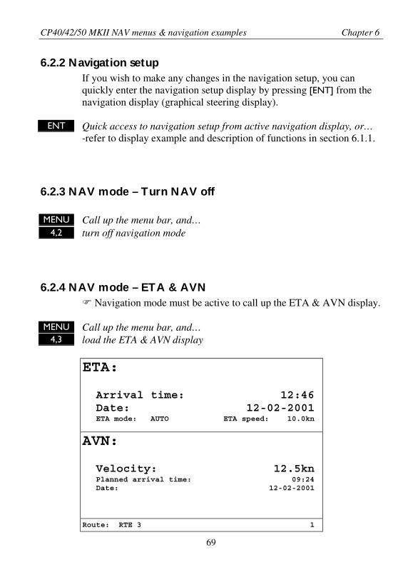
CP40/42/50 MKII NAV menus & navigation examples Chapter 6
69
6.2.2 Navigation setupIf you wish to make any changes in the navigation setup, you canquickly enter the navigation setup display by pressing [ENT] from thenavigation display (graphical steering display).
ENT Quick access to navigation setup from active navigation display, or…-refer to display example and description of functions in section 6.1.1.
6.2.3 NAV mode – Turn NAV off
MENU Call up the menu bar, and…4,2 turn off navigation mode
6.2.4 NAV mode – ETA & AVNNavigation mode must be active to call up the ETA & AVN display.
MENU Call up the menu bar, and…4,3 load the ETA & AVN display
ETA:
Arrival time: 12:46 Date: 12-02-2001 ETA mode: AUTO ETA speed: 10.0kn
AVN:
Velocity: 12.5kn Planned arrival time: 09:24 Date: 12-02-2001
Route: RTE 3 1
CP40/42/50 MKII NAV menus & navigation examples Chapter 6
70
ETA – Estimated Time of Arrival - refers to the inserted local time,and can be calculated to any point used for navigation.
AVN – Approximate Velocity Necessary – is automatically calculatedin knots after you key in the planned arrival time and date.
In route navigation the approaching point and present speed overground (AUTO) is automatically used for the calculation.
You can change to any waypoint in the route and also insert an alterna-tive ETA speed (MANUAL).
ENT Open for change – in route navigation the approaching point isautomatically suggested and present speed is used for calculation.
If required – go to, and…
0-9 Insert alternative routepoint – only in Route navigation.
Go to ETA mode, and…
+/- Select AUTO or MANUAL
Go to AVN, and…
0-9 Insert time and date
ENT Confirm entry
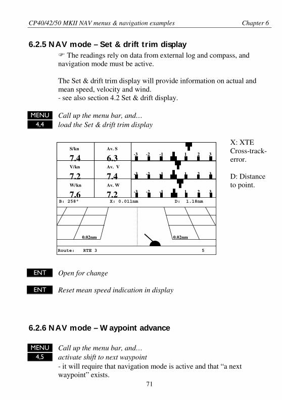
CP40/42/50 MKII NAV menus & navigation examples Chapter 6
71
6.2.5 NAV mode – Set & drift trim displayThe readings rely on data from external log and compass, and
navigation mode must be active.
The Set & drift trim display will provide information on actual andmean speed, velocity and wind.- see also section 4.2 Set & drift display.
MENU Call up the menu bar, and…4,4 load the Set & drift trim display
X: XTECross-track-error.
D: Distanceto point.
ENT Open for change
ENT Reset mean speed indication in display
6.2.6 NAV mode – Waypoint advance½
MENU Call up the menu bar, and…4,5 activate shift to next waypoint
- it will require that navigation mode is active and that “a nextwaypoint” exists.
Route: RTE 3 5
-3 -2 -1 1 2 3
-3 -2 -1 1 2 3
B: 258° X: 0.011nm D: 1.18nm
-3 -2 -1 1 2 3
W/kn
7.6Av. W
7.2
Av. V
7.4V/kn
7.2
Av. S
6.3S/kn
7.4
0.02nm0.02nm
CP40/42/50 MKII NAV menus & navigation examples Chapter 6
72
6.3 Anchor guard
MENU Call up the menu bar, and…4,5 activate the anchor guard function
- the chart display will provide an impression of the vessel’s position inrelation to the alarm circle.
To check/change the preset alarm distance:NAV Direct access to Navigation display
- or gain access via the menu:MENU Call up the menu bar, and…
4,1 load the navigation display
ENT Press [ENT] to call up the navigation setup display
Move cursor to the Anchor alarm distance
0-9 Enter new value with numeric keys
ENT Confirm the change
To turn Anchor guard off again:
MENU Call up the menu bar, and…4,2 turn anchor guard off
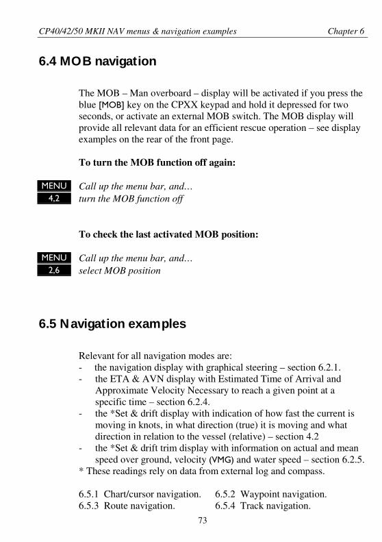
CP40/42/50 MKII NAV menus & navigation examples Chapter 6
73
6.4 MOB navigation
The MOB – Man overboard – display will be activated if you press theblue [MOB] key on the CPXX keypad and hold it depressed for twoseconds, or activate an external MOB switch. The MOB display willprovide all relevant data for an efficient rescue operation – see displayexamples on the rear of the front page.
To turn the MOB function off again:
MENU Call up the menu bar, and…4,2 turn the MOB function off
To check the last activated MOB position:
MENU Call up the menu bar, and…2,6 select MOB position
6.5 Navigation examples
Relevant for all navigation modes are:- the navigation display with graphical steering – section 6.2.1.- the ETA & AVN display with Estimated Time of Arrival and
Approximate Velocity Necessary to reach a given point at aspecific time – section 6.2.4.
- the *Set & drift display with indication of how fast the current ismoving in knots, in what direction (true) it is moving and whatdirection in relation to the vessel (relative) – section 4.2
- the *Set & drift trim display with information on actual and meanspeed over ground, velocity (VMG) and water speed – section 6.2.5.
* These readings rely on data from external log and compass.
6.5.1 Chart/cursor navigation. 6.5.2 Waypoint navigation.6.5.3 Route navigation. 6.5.4 Track navigation.
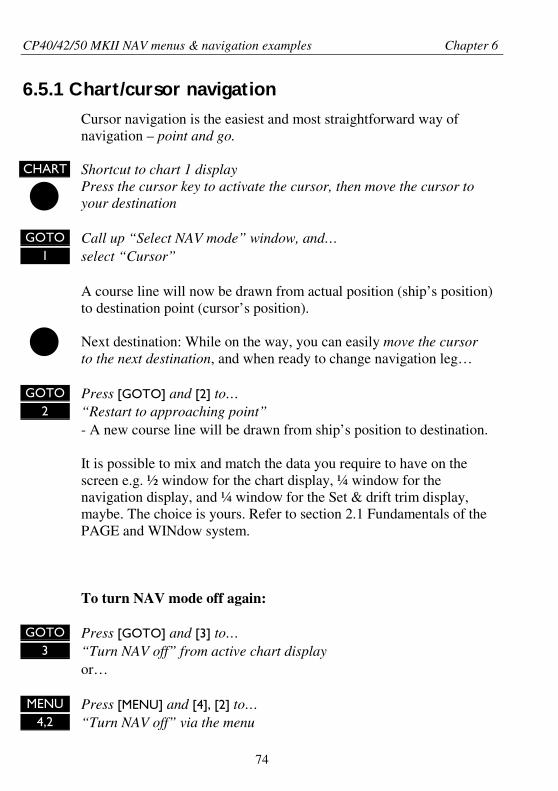
CP40/42/50 MKII NAV menus & navigation examples Chapter 6
74
6.5.1 Chart/cursor navigation
Cursor navigation is the easiest and most straightforward way ofnavigation – point and go.
CHART Shortcut to chart 1 displayPress the cursor key to activate the cursor, then move the cursor toyour destination
GOTO Call up “Select NAV mode” window, and…1 select “Cursor”
A course line will now be drawn from actual position (ship’s position)to destination point (cursor’s position).
Next destination: While on the way, you can easily move the cursorto the next destination, and when ready to change navigation leg…
GOTO Press [GOTO] and [2] to…2 “Restart to approaching point”
- A new course line will be drawn from ship’s position to destination.
It is possible to mix and match the data you require to have on thescreen e.g. ½ window for the chart display, ¼ window for thenavigation display, and ¼ window for the Set & drift trim display,maybe. The choice is yours. Refer to section 2.1 Fundamentals of thePAGE and WINdow system.
To turn NAV mode off again:
GOTO Press [GOTO] and [3] to…3 “Turn NAV off” from active chart display
or…
MENU Press [MENU] and [4], [2] to…4,2 “Turn NAV off” via the menu
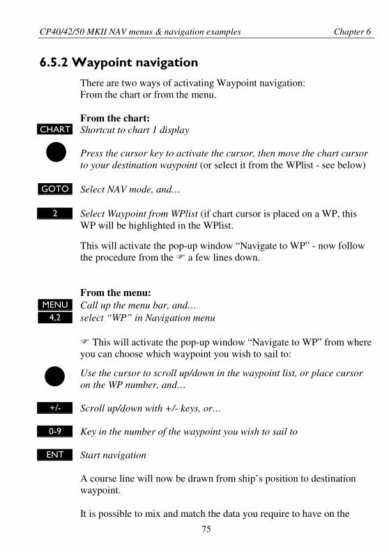
CP40/42/50 MKII NAV menus & navigation examples Chapter 6
75
6.5.2 Waypoint navigation
There are two ways of activating Waypoint navigation:From the chart or from the menu.
From the chart:CHART Shortcut to chart 1 display
Press the cursor key to activate the cursor, then move the chart cursorto your destination waypoint (or select it from the WPlist - see below)
GOTO Select NAV mode, and…
2 Select Waypoint from WPlist (if chart cursor is placed on a WP, thisWP will be highlighted in the WPlist.
This will activate the pop-up window “Navigate to WP” - now followthe procedure from the a few lines down.
From the menu:MENU Call up the menu bar, and…
4,2 select “WP” in Navigation menu
This will activate the pop-up window “Navigate to WP” from whereyou can choose which waypoint you wish to sail to:
Use the cursor to scroll up/down in the waypoint list, or place cursoron the WP number, and…
+/- Scroll up/down with +/- keys, or…
0-9 Key in the number of the waypoint you wish to sail to
ENT Start navigation
A course line will now be drawn from ship’s position to destinationwaypoint.
It is possible to mix and match the data you require to have on the
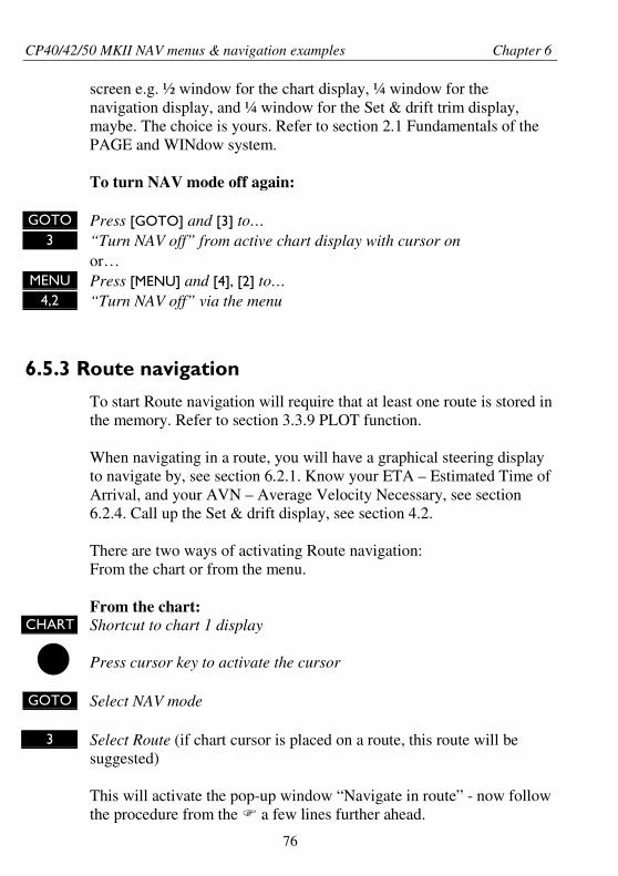
CP40/42/50 MKII NAV menus & navigation examples Chapter 6
76
screen e.g. ½ window for the chart display, ¼ window for thenavigation display, and ¼ window for the Set & drift trim display,maybe. The choice is yours. Refer to section 2.1 Fundamentals of thePAGE and WINdow system.
To turn NAV mode off again:
GOTO Press [GOTO] and [3] to…3 “Turn NAV off” from active chart display with cursor on
or…MENU Press [MENU] and [4], [2] to…
4,2 “Turn NAV off” via the menu
6.5.3 Route navigation
To start Route navigation will require that at least one route is stored inthe memory. Refer to section 3.3.9 PLOT function.
When navigating in a route, you will have a graphical steering displayto navigate by, see section 6.2.1. Know your ETA – Estimated Time ofArrival, and your AVN – Average Velocity Necessary, see section6.2.4. Call up the Set & drift display, see section 4.2.
There are two ways of activating Route navigation:From the chart or from the menu.
From the chart:CHART Shortcut to chart 1 display
Press cursor key to activate the cursor
GOTO Select NAV mode
3 Select Route (if chart cursor is placed on a route, this route will besuggested)
This will activate the pop-up window “Navigate in route” - now followthe procedure from the a few lines further ahead.
CP40/42/50 MKII NAV menus & navigation examples Chapter 6
77
From the menu:MENU Call up the menu bar, and…
4,3 select “ROUTE” in Navigation menu
This will activate the pop-up window “Navigate in route” fromwhere you can choose which route you wish to select for navigation:
+/- Scroll up/down in the route list until the correct route number / nameappears
Use the cursor to move around in the window if anything needs to bechanged – such as Direction in route, etc.
0-9 Key in the number of the waypoint you wish to sail to
ENT Start navigation
A course line will now be drawn from ship’s position to the firstwaypoint in the route.
It is possible to mix and match the data you require to have on thescreen e.g. ½ window for the chart display, ¼ window for thenavigation display, and ¼ window for the Set & drift trim display orETA & AVN display, maybe. The choice is yours. Refer to section 2.1Fundamentals of the PAGE and WINdow system.
GOTO Pressing [GOTO] from chart display during navigation will activate anINFO window with the following functions to choose from:1. Advance (to next waypoint in route)2. Restart to approaching point (in case you have drifted off course)3. Turn NAV OFF.
MENU Pressing [MENU] and [4], from an active data display during navigation4 will give access to the following displays / feature:
1. Navigation display2. Turn NAV off3. ETA & AVN4. Set & drift trim5. WP advance
CP40/42/50 MKII NAV menus & navigation examples Chapter 6
78
6.5.4 Track navigation
A track is created by a series of trackpoints connected by track lines.Using a track for navigation is somewhat like navigating in a routewith many waypoints.
To start Track navigation will require that at least one track is storedin the memory. Tracks which are not yet completed can not be used fornavigation. Refer to section 5.5 Start / Stop track.
When navigating in a track, you will have a graphical steering displayto navigate by, see section 6.2.1. Know your ETA – Estimated Time ofArrival, and your AVN – Average Velocity Necessary, see section6.2.4. Call up the Set & drift display, see section 4.2.
There are two ways of activating Track navigation:From the chart or from the menu.
From the chart:CHART Load chart display in active window, and…
Press cursor key to activate the cursor
GOTO Select NAV mode
4 Select Track (if chart cursor is placed on a track, this track will besuggested).
This will activate the pop-up window “Navigate in track” - now followthe procedure from the a few lines further ahead.
From the menu:MENU Call up the menu bar, and…
4,4 select “TRACK” in Navigation menu
This will activate the pop-up window “Navigate in track” from
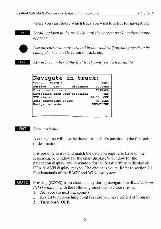
CP40/42/50 MKII NAV menus & navigation examples Chapter 6
79
where you can choose which track you wish to select for navigation:
+/- Scroll up/down in the track list until the correct track number / nameappears
Use the cursor to move around in the window if anything needs to bechanged – such as Direction in track, etc.
0-9 Key in the number of the first trackpoint you wish to sail to
Navigate in track:Track: TRACK 1 0001Bearing: 224° Distance: 0.000nmDirection in track: FORWARDNavigation from your position: YESXTE alarm: 00.10 OFFAuto trackpoint shift: WP-lineNavigation mode: RHUMBLINE
ENT Start navigation
A course line will now be drawn from ship’s position to the first pointof destination.
It is possible to mix and match the data you require to have on thescreen e.g. ½ window for the chart display, ¼ window for thenavigation display, and ¼ window for the Set & drift trim display orETA & AVN display, maybe. The choice is yours. Refer to section 2.1Fundamentals of the PAGE and WINdow system.
GOTO Pressing [GOTO] from chart display during navigation will activate anINFO window with the following functions to choose from:1. Advance (to next trackpoint)2. Restart to approaching point (in case you have drifted off course)3. Turn NAV OFF.
CP40/42/50 MKII NAV menus & navigation examples Chapter 6
80
MENU Pressing [MENU] and [4], from an active data display during navigation4 will give access to the following displays / feature:
1. Navigation display2. Turn NAV off3. ETA & AVN4. Set & drift trim5. WP advance
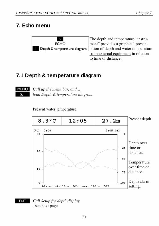
CP40/42/50 MKII ECHO and SPECIAL menus Chapter 7
81
7. Echo menu
_5_ECHO
_1_ Depth & temperature diagram
The depth and temperature “instru-ment” provides a graphical presen-tation of depth and water temperaturefrom external equipment in relationto time or distance.
7.1 Depth & temperature diagram
MENU Call up the menu bar, and…5,1 load Depth & temperature diagram
Present water temperature.
8.3°C 12:05 27.2m
[°C] 7:00 7:05 [m] 30 - - 0
- 25 20 -
- 50
10 - - 75
0 - - 100 Alarm: min 10 m ON. max 100 m OFF
Present depth.
Depth overtime ordistance.
Temperatureover time ordistance.
Depth alarmsetting.
ENT Call Setup for depth display- see next page.
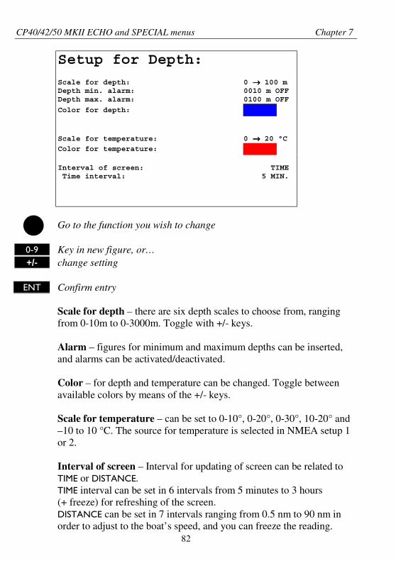
CP40/42/50 MKII ECHO and SPECIAL menus Chapter 7
82
Setup for Depth:
Scale for depth: 0 →→→→ 100 mDepth min. alarm: 0010 m OFFDepth max. alarm: 0100 m OFF
Color for depth:
Scale for temperature: 0 →→→→ 20 °C
Color for temperature:
Interval of screen: TIME Time interval: 5 MIN.
Go to the function you wish to change
0-9 Key in new figure, or…+/- change setting
ENT Confirm entry
Scale for depth – there are six depth scales to choose from, rangingfrom 0-10m to 0-3000m. Toggle with +/- keys.
Alarm – figures for minimum and maximum depths can be inserted,and alarms can be activated/deactivated.
Color – for depth and temperature can be changed. Toggle betweenavailable colors by means of the +/- keys.
Scale for temperature – can be set to 0-10°, 0-20°, 0-30°, 10-20° and–10 to 10 °C. The source for temperature is selected in NMEA setup 1or 2.
Interval of screen – Interval for updating of screen can be related toTIME or DISTANCE.TIME interval can be set in 6 intervals from 5 minutes to 3 hours(+ freeze) for refreshing of the screen.DISTANCE can be set in 7 intervals ranging from 0.5 nm to 90 nm inorder to adjust to the boat’s speed, and you can freeze the reading.
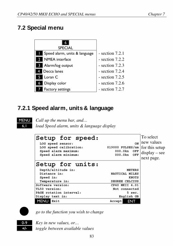
CP40/42/50 MKII ECHO and SPECIAL menus Chapter 7
83
7.2 Special menu
_6_SPECIAL
_1_ Speed alarm, units & language - section 7.2.1_2_ NMEA interface - section 7.2.2_3_ Alarm/log output - section 7.2.3_4_ Decca lanes - section 7.2.4_5_ Loran C - section 7.2.5_6_ Display color - section 7.2.6_7_ Factory settings - section 7.2.7
7.2.1 Speed alarm, units & language
MENU Call up the menu bar, and…6,1 load Speed alarm, units & language display
Setup for speed: LOG speed sensor: ON LOG speed calibration: 019000 PULSES/nm Speed alarm maximum: 000.0kn OFF Speed alarm minimum: 000.0kn OFF
To selectnew valuesfor this setupdisplay – seenext page.
Setup for units: Depth/altitude in: METERS Distance in: NAUTICAL MILES Speed in: KNOTS Temperature in: DEGREE CELCIUSSoftware version: CP40 MKII 4.01TL50 version: Not connectedPAGE rotation interval: 5 sec.Display text in: English GB
MENU Exit Accept ENT
go to the function you wish to change
0-9 Key in new values, or…+/- toggle between available values
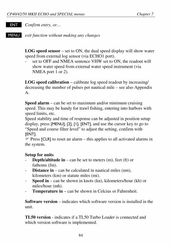
CP40/42/50 MKII ECHO and SPECIAL menus Chapter 7
84
ENT Confirm entry, or…
MENU exit function without making any changes
LOG speed sensor – set to ON, the dual speed display will show waterspeed from external log sensor (via ECHO1 port).- set to OFF and NMEA sentence VHW set to ON, the readout will
show water speed from external water speed instrument (viaNMEA port 1 or 2).
LOG speed calibration – calibrate log speed readout by increasing/decreasing the number of pulses per nautical mile – see also AppendixA.
Speed alarm – can be set to maximum and/or minimum cruisingspeed. This may be handy for trawl fishing, entering into harbors withspeed limits, etc.Speed stability and time of response can be adjusted in position setupdisplay, press [MENU], [2], [1], [ENT], and use the cursor key to go to“Speed and course filter level” to adjust the setting, confirm with[ENT].
Press [CLR] to reset an alarm – this applies to all activated alarms inthe system.
Setup for units- Depth/altitude in – can be set to meters (m), feet (ft) or
fathoms (fm).- Distance in – can be calculated in nautical miles (nm),
kilometers (km) or statute miles (mi).- Speed in – can be shown in knots (kn), kilometers/hour (kh) or
miles/hour (mh).- Temperature in – can be shown in Celcius or Fahrenheit.
Software version – indicates which software version is installed in theunit.
TL50 version - indicates if a TL50 Turbo Loader is connected andwhich version software is implemented.
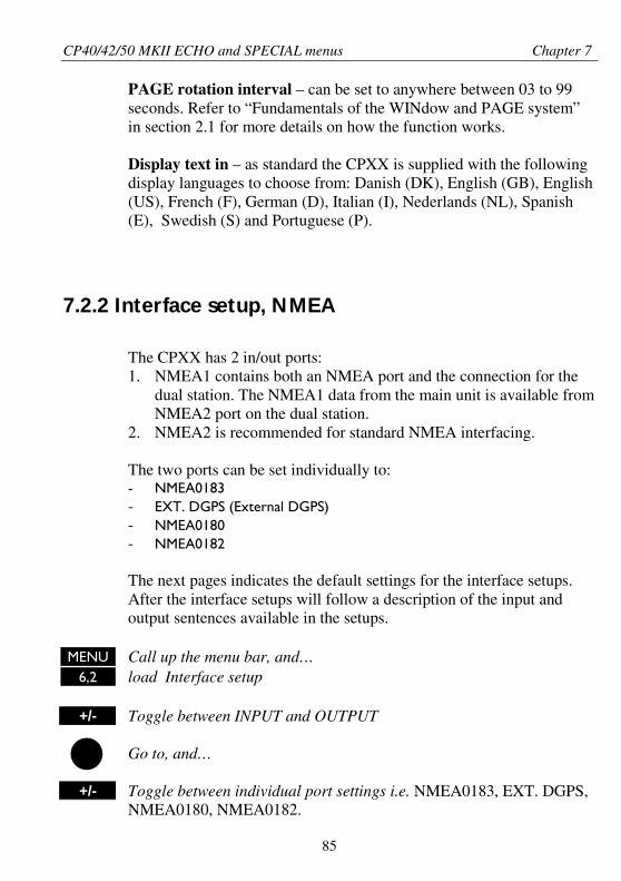
CP40/42/50 MKII ECHO and SPECIAL menus Chapter 7
85
PAGE rotation interval – can be set to anywhere between 03 to 99seconds. Refer to “Fundamentals of the WINdow and PAGE system”in section 2.1 for more details on how the function works.
Display text in – as standard the CPXX is supplied with the followingdisplay languages to choose from: Danish (DK), English (GB), English(US), French (F), German (D), Italian (I), Nederlands (NL), Spanish(E), Swedish (S) and Portuguese (P).
7.2.2 Interface setup, NMEA
The CPXX has 2 in/out ports:1. NMEA1 contains both an NMEA port and the connection for the
dual station. The NMEA1 data from the main unit is available fromNMEA2 port on the dual station.
2. NMEA2 is recommended for standard NMEA interfacing.
The two ports can be set individually to:- NMEA0183- EXT. DGPS (External DGPS)- NMEA0180- NMEA0182
The next pages indicates the default settings for the interface setups.After the interface setups will follow a description of the input andoutput sentences available in the setups.
MENU Call up the menu bar, and…6,2 load Interface setup
+/- Toggle between INPUT and OUTPUT
Go to, and…
+/- Toggle between individual port settings i.e. NMEA0183, EXT. DGPS,NMEA0180, NMEA0182.
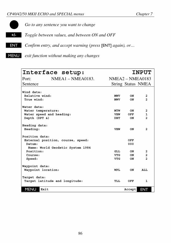
CP40/42/50 MKII ECHO and SPECIAL menus Chapter 7
86
Go to any sentence you want to change
+/- Toggle between values, and between ON and OFF
ENT Confirm entry, and accept warning (press [ENT] again), or…
MENU exit function without making any changes
Interface setup: INPUTPort: NMEA1 – NMEA0183. NMEA2 – NMEA0183Sentence String Status NMEA
Wind data: Relative wind: MWV ON 2 True wind: MWV ON 2
Water data: Water temperature: MTW ON 2 Water speed and heading: VHW OFF 1 Depth (DPT &) DBT ON 2
Heading data: Heading: VHW ON 2
Position data: External position, course, speed: OFF Datum: 000 Name: World Geodetic System 1984 Position: GLL ON 2 Course: VTG ON 2 Speed: VTG ON 2
Waypoint data: Waypoint location: WPL ON ALL
Target data: Target latitude and longitude: TLL OFF 1
MENU Exit Accept ENT
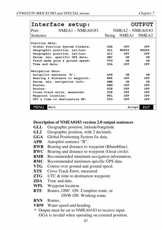
CP40/42/50 MKII ECHO and SPECIAL menus Chapter 7
87
Interface setup: OUTPUTPort: NMEA1 – NMEA0183. NMEA2 – NMEA0183Sentence String NMEA1 NMEA2
Position data: Global Position System fixdata: GGA OFF OFF Geographic position, Lat/Lon: GLL WGS84 WGS84 Geographic position, Lat/Lon: GL2 OFF OFF Recom. min. specific GPS data: RMC ON ON Track made good & ground speed: VTG ON ON Time and date: ZDA OFF OFF
Navigation data: Autopilot sentence ‘B’: APB ON ON Bearing & distance to waypoint: BWR OFF OFF Recom. min. navigation info: RMB ON ON Routes: RNN OFF OFF Routes: RTE OFF OFF Cross-track error, measured: XTE OFF OFF Waypoint location: WPL OFF OFF UTC & time to destination WP: ZTG OFF OFF
MENU Exit Accept ENT
Description of NMEA0183 version 2.0 output sentencesGLLGL2GGAAPBBWRBWCRMBRMCVTG
Geographic position, latitude/longitude.Geographic position, with 2 decimals.Global Positioning System fix data.Autopilot sentence “B”.Bearing and distance to waypoint (Rhumbline).Bearing and distance to waypoint (Great circle).Recommended minimum navigation information.Recommended minimum specific GPS data.Course over ground and ground speed.
XTEZTGZDAWPL
Cross-Track-Error, measuredUTC & time to destination waypoint.Time and date.Waypoint location.
RTE
RNNVHW
Routes, ONC ON Complete route, orONW ON Working route.
Routes.Water speed and heading.
Output must be set to NMEA0183 to receive input.GGA is invalid when operating on external position.
CP40/42/50 MKII ECHO and SPECIAL menus Chapter 7
88
Description of NMEA0183 instrument inputWPLTLLMTWVHWHDTHDGHDMVWTVWRMWVDBSDBKDBTDPT
Waypoint data. (will only be updated every 5 seconds)Target data. (will only be updated every 5 seconds)Water temperature.Water speed and heading.Heading, TrueHeading, Deviation and VariationHeading, MagneticTrue wind speed and angle.Relative wind speed and angle.Wind speed and angle.Depth below surface.Depth below keel.Depth below transducer.Depth, including offset.
Description of NMEA0183 external position, heading and speedinputGLLRMARMCGGAVTG
Geographic position, latitude/longitude.Recommended minimum specific Loran C data.Recommended minimum specific GPS data.Global Positioning System fix data.Track made good (course) and ground speed.
Input is only valid when output is set to NMEA0183.
The external position can be set to OFF, ON, or Dead reckoning whereyou can enter a speed value.
When set to Dead reckoning, the system can function as a Navigationsimulator, which can be used for demonstration purpose or forpracticing ‘live’ navigation in ‘off season’. See further details inAppendix A under ‘Navigation simulator’.
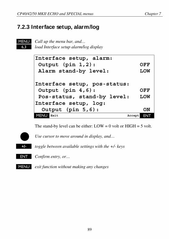
CP40/42/50 MKII ECHO and SPECIAL menus Chapter 7
89
7.2.3 Interface setup, alarm/log
MENU Call up the menu bar, and…6,3 load Interface setup alarm/log display
Interface setup, alarm: Output (pin 1,2): OFF Alarm stand-by level: LOW
Interface setup, pos-status: Output (pin 4,6): OFF Pos-status, stand-by level: LOWInterface setup, log: Output (pin 5,6): ONMENU Exit Accept ENT
The stand-by level can be either: LOW = 0 volt or HIGH = 5 volt.
Use cursor to move around in display, and…
+/- toggle between available settings with the +/- keys
ENT Confirm entry, or…
MENU exit function without making any changes
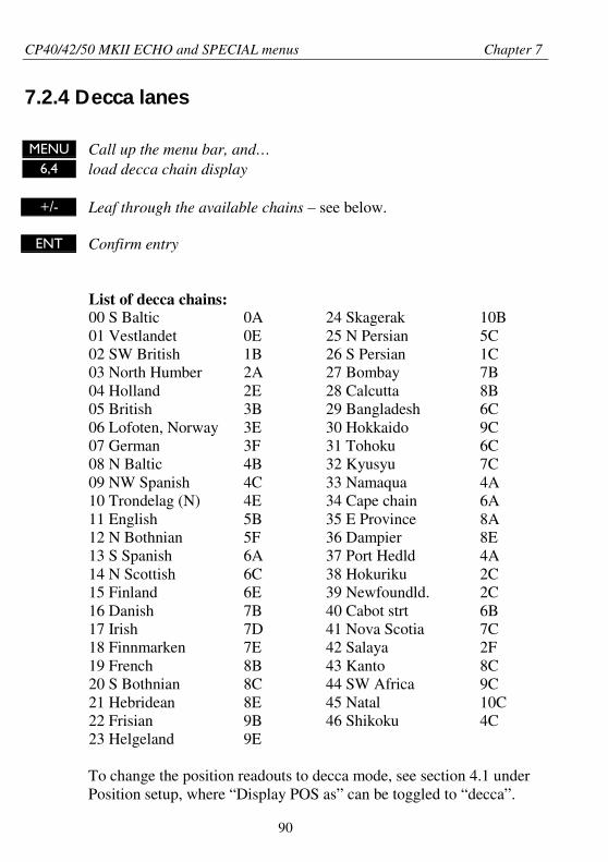
CP40/42/50 MKII ECHO and SPECIAL menus Chapter 7
90
7.2.4 Decca lanes
MENU Call up the menu bar, and…6,4 load decca chain display
+/- Leaf through the available chains – see below.
ENT Confirm entry
List of decca chains:00 S Baltic01 Vestlandet02 SW British03 North Humber04 Holland05 British06 Lofoten, Norway07 German08 N Baltic09 NW Spanish10 Trondelag (N)11 English12 N Bothnian13 S Spanish14 N Scottish15 Finland16 Danish17 Irish18 Finnmarken19 French20 S Bothnian21 Hebridean22 Frisian23 Helgeland
0A0E1B2A2E3B3E3F4B4C4E5B5F6A6C6E7B7D7E8B8C8E9B9E
24 Skagerak25 N Persian26 S Persian27 Bombay28 Calcutta29 Bangladesh30 Hokkaido31 Tohoku32 Kyusyu33 Namaqua34 Cape chain35 E Province36 Dampier37 Port Hedld38 Hokuriku39 Newfoundld.40 Cabot strt41 Nova Scotia42 Salaya43 Kanto44 SW Africa45 Natal46 Shikoku
10B5C1C7B8B6C9C6C7C4A6A8A8E4A2C2C6B7C2F8C9C10C4C
To change the position readouts to decca mode, see section 4.1 underPosition setup, where “Display POS as” can be toggled to “decca”.
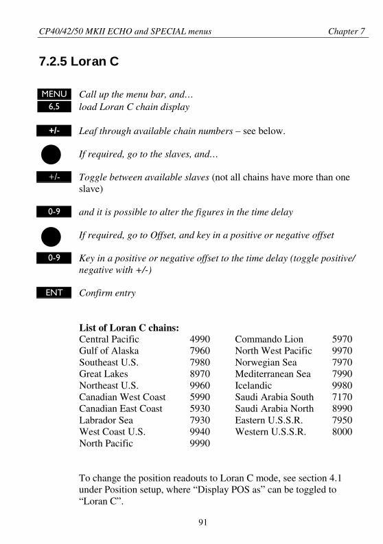
CP40/42/50 MKII ECHO and SPECIAL menus Chapter 7
91
7.2.5 Loran C
MENU Call up the menu bar, and…6,5 load Loran C chain display
+/- Leaf through available chain numbers – see below.
If required, go to the slaves, and…
+/- Toggle between available slaves (not all chains have more than oneslave)
0-9 and it is possible to alter the figures in the time delay
If required, go to Offset, and key in a positive or negative offset
0-9 Key in a positive or negative offset to the time delay (toggle positive/negative with +/-)
ENT Confirm entry
List of Loran C chains:Central PacificGulf of AlaskaSoutheast U.S.Great LakesNortheast U.S.Canadian West CoastCanadian East CoastLabrador SeaWest Coast U.S.North Pacific
4990796079808970996059905930793099409990
Commando LionNorth West PacificNorwegian SeaMediterranean SeaIcelandicSaudi Arabia SouthSaudi Arabia NorthEastern U.S.S.R.Western U.S.S.R.
597099707970799099807170899079508000
To change the position readouts to Loran C mode, see section 4.1under Position setup, where “Display POS as” can be toggled to“Loran C”.
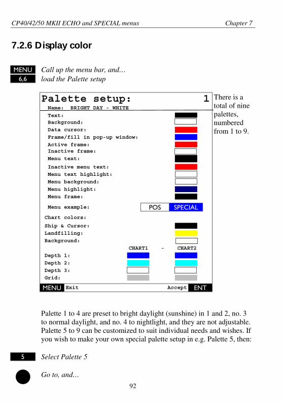
CP40/42/50 MKII ECHO and SPECIAL menus Chapter 7
92
7.2.6 Display color
MENU Call up the menu bar, and…6,6 load the Palette setup
Palette setup: 1 Name: BRIGHT DAY - WHITE
Text: Background:
Data cursor:
Frame/fill in pop-up window:
Active frame: Inactive frame:
Menu text:
Inactive menu text:
Menu text highlight:
Menu background:
Menu highlight:
Menu frame:
Menu example: POS SPECIAL
There is atotal of ninepalettes,numberedfrom 1 to 9.
Chart colors:
Ship & Cursor:
Landfilling:
Background:
CHART1 - CHART2
Depth 1:
Depth 2:
Depth 3:
Grid:
MENU Exit Accept ENT
Palette 1 to 4 are preset to bright daylight (sunshine) in 1 and 2, no. 3to normal daylight, and no. 4 to nightlight, and they are not adjustable.Palette 5 to 9 can be customized to suit individual needs and wishes. Ifyou wish to make your own special palette setup in e.g. Palette 5, then:
5 Select Palette 5
Go to, and…
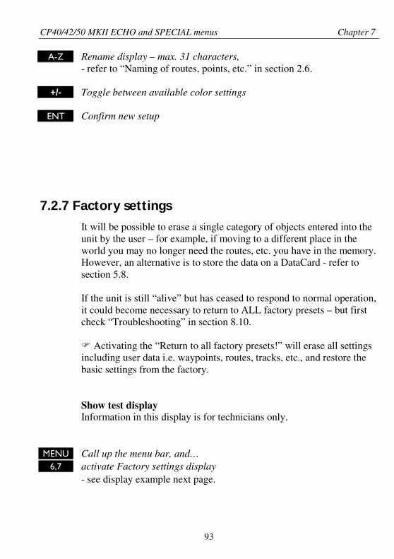
CP40/42/50 MKII ECHO and SPECIAL menus Chapter 7
93
A-Z Rename display – max. 31 characters,- refer to “Naming of routes, points, etc.” in section 2.6.
+/- Toggle between available color settings
ENT Confirm new setup
7.2.7 Factory settings
It will be possible to erase a single category of objects entered into theunit by the user – for example, if moving to a different place in theworld you may no longer need the routes, etc. you have in the memory.However, an alternative is to store the data on a DataCard - refer tosection 5.8.
If the unit is still “alive” but has ceased to respond to normal operation,it could become necessary to return to ALL factory presets – but firstcheck “Troubleshooting” in section 8.10.
Activating the “Return to all factory presets!” will erase all settingsincluding user data i.e. waypoints, routes, tracks, etc., and restore thebasic settings from the factory.
Show test displayInformation in this display is for technicians only.
MENU Call up the menu bar, and…6,7 activate Factory settings display
- see display example next page.
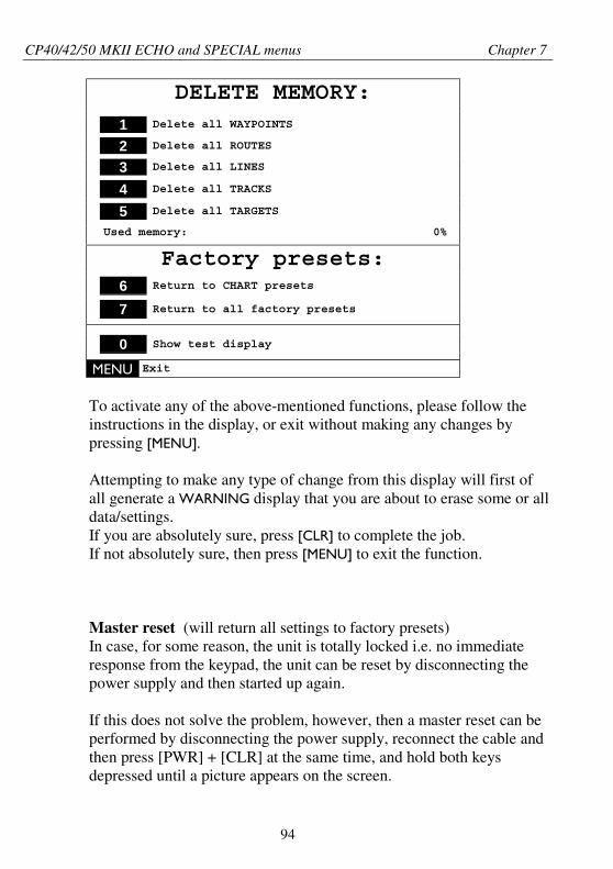
CP40/42/50 MKII ECHO and SPECIAL menus Chapter 7
94
DELETE MEMORY:
1 Delete all WAYPOINTS
2 Delete all ROUTES
3 Delete all LINES
4 Delete all TRACKS
5 Delete all TARGETS
Used memory: 0%
Factory presets:6 Return to CHART presets
7 Return to all factory presets
0 Show test display
MENU Exit
To activate any of the above-mentioned functions, please follow theinstructions in the display, or exit without making any changes bypressing [MENU].
Attempting to make any type of change from this display will first ofall generate a WARNING display that you are about to erase some or alldata/settings.If you are absolutely sure, press [CLR] to complete the job.If not absolutely sure, then press [MENU] to exit the function.
Master reset (will return all settings to factory presets)In case, for some reason, the unit is totally locked i.e. no immediateresponse from the keypad, the unit can be reset by disconnecting thepower supply and then started up again.
If this does not solve the problem, however, then a master reset can beperformed by disconnecting the power supply, reconnect the cable andthen press [PWR] + [CLR] at the same time, and hold both keysdepressed until a picture appears on the screen.
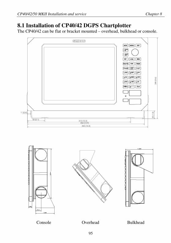
CP40/42/50 MKII Installation and service Chapter 8
95
8.1 Installation of CP40/42 DGPS ChartplotterThe CP40/42 can be flat or bracket mounted – overhead, bulkhead or console.
Console Overhead Bulkhead
245
(9.6
)25
(1.0
)
312 (12 .3)354 (13 .9)
365 (14 .4)
52 (2 .1 )
11 (0 .4 )
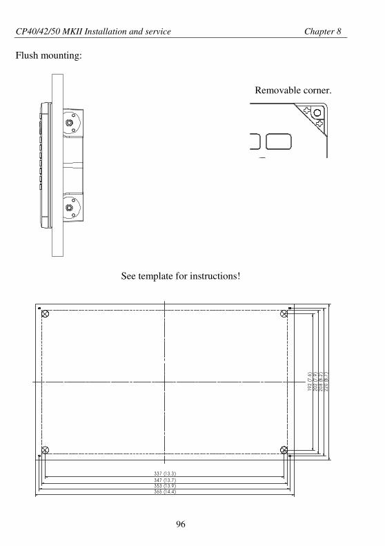
CP40/42/50 MKII Installation and service Chapter 8
96
Flush mounting:
Removable corner.
See template for instructions!
337 (13 .3 )347 (13 .7 )353 (13 .9 )365 (14 .4 )
192
(7.6
)20
2(7
.9)
208
(8.2
)22
0(8
.7)
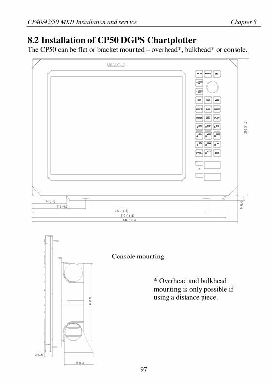
CP40/42/50 MKII Installation and service Chapter 8
97
295
(11.
6)
74 (2 .9)
116 (4 .6)376 (1 4.8)
419 (1 6.5)
445 (1 7.5)
9(0
.4)
8.2 Installation of CP50 DGPS ChartplotterThe CP50 can be flat or bracket mounted – overhead*, bulkhead* or console.
Console mounting
* Overhead and bulkheadmounting is only possible ifusing a distance piece.
2 0 (0.8)
196
(7.7
)
7 5 (3 .0)
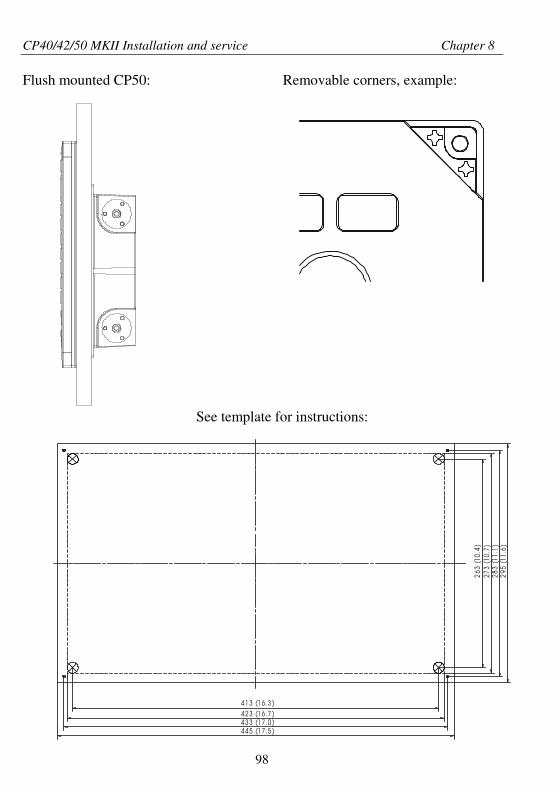
CP40/42/50 MKII Installation and service Chapter 8
98
Flush mounted CP50: Removable corners, example:
See template for instructions:
41 3 (1 6 .3 )
263
(10.
4)
42 3 (1 6 .7 )43 3 (1 7 .0 )44 5 (1 7 .5 )
273
(10.
7)28
3(1
1.1)
295
(11.
6)
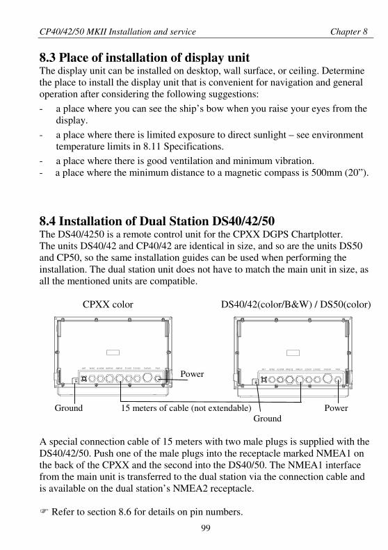
CP40/42/50 MKII Installation and service Chapter 8
99
8.3 Place of installation of display unitThe display unit can be installed on desktop, wall surface, or ceiling. Determinethe place to install the display unit that is convenient for navigation and generaloperation after considering the following suggestions:
- a place where you can see the ship’s bow when you raise your eyes from thedisplay.
- a place where there is limited exposure to direct sunlight – see environmenttemperature limits in 8.11 Specifications.
- a place where there is good ventilation and minimum vibration.- a place where the minimum distance to a magnetic compass is 500mm (20”).
8.4 Installation of Dual Station DS40/42/50The DS40/4250 is a remote control unit for the CPXX DGPS Chartplotter.The units DS40/42 and CP40/42 are identical in size, and so are the units DS50and CP50, so the same installation guides can be used when performing theinstallation. The dual station unit does not have to match the main unit in size, asall the mentioned units are compatible.
CPXX color DS40/42(color/B&W) / DS50(color)
Power
Ground 15 meters of cable (not extendable) PowerGround
A special connection cable of 15 meters with two male plugs is supplied with theDS40/42/50. Push one of the male plugs into the receptacle marked NMEA1 onthe back of the CPXX and the second into the DS40/50. The NMEA1 interfacefrom the main unit is transferred to the dual station via the connection cable andis available on the dual station’s NMEA2 receptacle.
Refer to section 8.6 for details on pin numbers.
AN T W I N D AL AR M N M E A2 N M E A1 E CH O1 E CH O2 R AD A R P W R AN T W I N D AL AR M N M E A 2 N M E A 1 E CH O1 E CH O2 R AD AR P W R
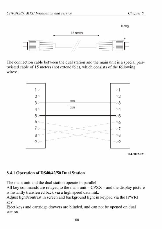
CP40/42/50 MKII Installation and service Chapter 8
100
The connection cable between the dual station and the main unit is a special pair-twisted cable of 15 meters (not extendable), which consists of the followingwires:
104.3002.023
8.4.1 Operation of DS40/42/50 Dual Station
The main unit and the dual station operate in parallel.All key commands are relayed to the main unit – CPXX – and the display pictureis instantly transferred back via a high speed data link.Adjust light/contrast in screen and background light in keypad via the [PWR]key.Eject keys and cartridge drawers are blinded, and can not be opened on dualstation.
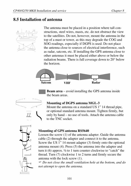
CP40/42/50 MKII Installation and service Chapter 8
101
5
6
7
21
3
4
8.5 Installation of antenna
The antenna must be placed in a position where tall con-structions, steel wires, masts, etc. do not obstruct the viewto the satellites. Do not, however, mount the antenna in thetop of a mast or tower, as this may degrade the COG andSOG readings, especially if DGPS is used. Do not placethe antenna close to sources of electrical interference, suchas radar, satcom, etc. If installing the GPS antenna close toother antennas it must be placed either above or below theradiation beams. There is full coverage down to 20° belowthe horizon.
Beam area – avoid installing the GPS antenna insidethe beam areas.
Mounting of DGPS antenna MGL-3Mount the antenna on a standard US 1” 14 thread pipe,or optional standard antenna mount. Tighten firmly, butonly by hand – no use of tools. Attach the antenna cableto the TNC socket.
Mounting of GPS antenna RS5640Loosen the screw (1) of the antenna adapter. Guide the antennacable (2) through the adapter and connect it to the antenna.Screw the US 1” 14 mount adapter (3) firmly onto the optionalantenna mount (4). Press (5) the antenna into the adapter andturn it (6) approx. ½ to 1 turn counter clockwise to “catch” thethread. Turn (7) clockwise 1 to 2 turns and firmly secure theantenna with the lock screw (1).
Do not close the small ventilation hole at the bottom, and donot attempt to open the antenna.
VHFSatcom Radar
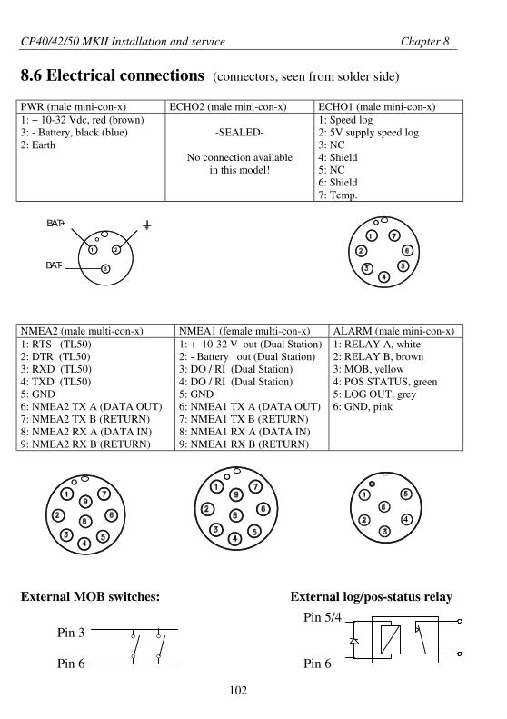
CP40/42/50 MKII Installation and service Chapter 8
102
° °
° °
8.6 Electrical connections (connectors, seen from solder side)
PWR (male mini-con-x) ECHO2 (male mini-con-x) ECHO1 (male mini-con-x)1: + 10-32 Vdc, red (brown)3: - Battery, black (blue)2: Earth
-SEALED-
No connection availablein this model!
1: Speed log2: 5V supply speed log3: NC4: Shield5: NC6: Shield7: Temp.
NMEA2 (male multi-con-x) NMEA1 (female multi-con-x) ALARM (male mini-con-x)1: RTS (TL50)2: DTR (TL50)3: RXD (TL50)4: TXD (TL50)5: GND6: NMEA2 TX A (DATA OUT)7: NMEA2 TX B (RETURN)8: NMEA2 RX A (DATA IN)9: NMEA2 RX B (RETURN)
1: + 10-32 V out (Dual Station)2: - Battery out (Dual Station)3: DO / RI (Dual Station)4: DO / RI (Dual Station)5: GND6: NMEA1 TX A (DATA OUT)7: NMEA1 TX B (RETURN)8: NMEA1 RX A (DATA IN)9: NMEA1 RX B (RETURN)
1: RELAY A, white2: RELAY B, brown3: MOB, yellow4: POS STATUS, green5: LOG OUT, grey6: GND, pink
External MOB switches: External log/pos-status relay
Pin 5/4Pin 3
Pin 6 Pin 6
°BAT-
BAT+ °
° °
4
CP40/42/50 MKII Installation and service Chapter 8
103
8.6.1 Power supply connectionsThe internal voltage regulator will allow the CPXX to operate normally over thepower supply voltage range from 10 to 32 Vdc. Connection between the CPXXand the external power supply is accomplished by means of the supplied powercable, which is approximately 1.5 meters long.
After connecting the cable to the power source, push the plug as far as it will gointo the three pin receptacle marked “PWR” on the rear of the cabinet and turnthe plug’s coupling ring clockwise until it makes a click.
8.6.2 FuseWarning! A fuse should always be installed to protect the unit.Using a fuse which is not specified for your equipment can cause it to blow theinstant the CPXX is switched on or it will not protect the equipment as intended– see fuse rating in section 8.11 Specifications.
8.6.3 NMEA0183 interface connectionsNMEA0183 interface connections are made to the receptacle marked “NMEA1”or “NMEA2” on the rear of the cabinet – turn the plug’s coupling ring clockwiseuntil it stops.
The CPXX must be turned off while connecting/disconnecting the interfacecable.
CP40/42/50 MKII Installation and service Chapter 8
104
8.7 Optional connections
General e.g. Autopilot or performance instrumentsCPXX NMEAPin 6 White TX A (DATA OUTPin 7 Brown TX B (RETURN)Pin 8 Yellow RX A (DATA IN)Pin 9 Green RX B (RETURN)
EQ40/50 EchosounderCPXX NMEA EQ40/50 NMEAPin 6 White TX A (DATA OUT) Pin 8 Yellow RX A (DATA IN)Pin 7 Brown TX B (RETURN) Pin 9 Green RX B (RETURN)Pin 8 Yellow RX A (DATA IN) Pin 6 White TX A (DATA OUT)Pin 9 Green RX B (RETURN) Pin 7 Brown TX B (RETURN)
RS2800 Color TrackplotterCPXX NMEA RS2800 Port 1 to 4Pin 6 White TX A (DATA OUT) Pin 5Pin 7 Brown TX B (RETURN) Pin 9
Differential Beacon Receiver (Set Interface to EXT. DGPS)CPXX NMEAPin 8 Yellow RX A (DATA IN)Pin 9 Green RX B (RETURN)
IS11 (Dataline) Data BoxCPXX NMEA Data BoxPin 6 White TX A (DATA OUT) + Radio nav inputPin 7 Brown TX B (RETURN) -Pin 8 Yellow RX A (DATA IN) WHT NMEA bus toPin 9 Green RX B (RETURN) GRN repeaters
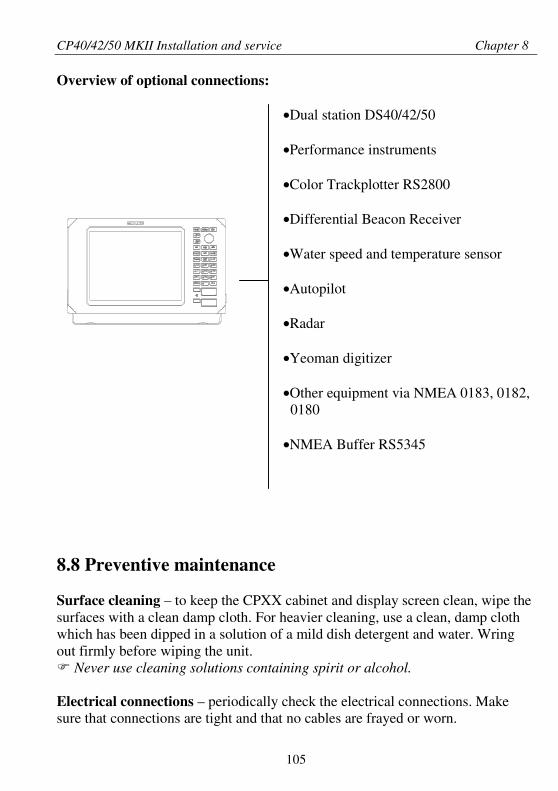
CP40/42/50 MKII Installation and service Chapter 8
105
Overview of optional connections:
•Dual station DS40/42/50
•Performance instruments
•Color Trackplotter RS2800
•Differential Beacon Receiver
•Water speed and temperature sensor
•Autopilot
•Radar
•Yeoman digitizer
•Other equipment via NMEA 0183, 0182,0180
•NMEA Buffer RS5345
8.8 Preventive maintenance
Surface cleaning – to keep the CPXX cabinet and display screen clean, wipe thesurfaces with a clean damp cloth. For heavier cleaning, use a clean, damp clothwhich has been dipped in a solution of a mild dish detergent and water. Wringout firmly before wiping the unit.
Never use cleaning solutions containing spirit or alcohol.
Electrical connections – periodically check the electrical connections. Makesure that connections are tight and that no cables are frayed or worn.
CP40/42/50 MKII Installation and service Chapter 8
106
8.9 Repair and service
The CPXX is sealed and does not contain any user serviceable parts. Opening ofthis unit will void its warranty. If the CPXX requires servicing or repair, call yourauthorized SIMRAD dealer, but first check section 8.10 Troubleshooting.
Spare parts – fuses may be bought from a chandler or a marine supply store.Use only fuses specified for this unit – see 8.11 Specifications.If you require a SIMRAD part, please contact your authorized dealer.
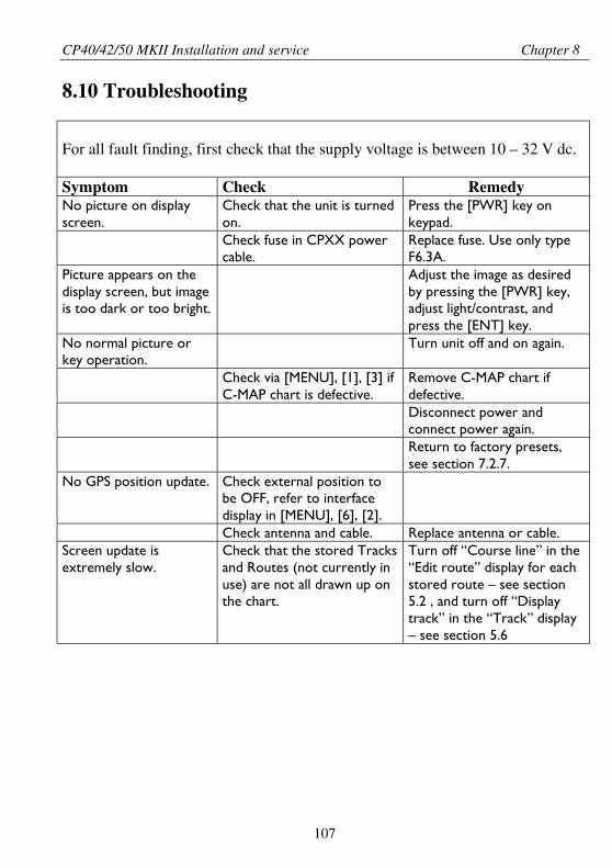
CP40/42/50 MKII Installation and service Chapter 8
107
8.10 Troubleshooting
For all fault finding, first check that the supply voltage is between 10 – 32 V dc.
Symptom Check RemedyNo picture on displayscreen.
Check that the unit is turnedon.
Press the [PWR] key onkeypad.
Check fuse in CPXX powercable.
Replace fuse. Use only typeF6.3A.
Picture appears on thedisplay screen, but imageis too dark or too bright.
Adjust the image as desiredby pressing the [PWR] key,adjust light/contrast, andpress the [ENT] key.
No normal picture orkey operation.
Turn unit off and on again.
Check via [MENU], [1], [3] ifC-MAP chart is defective.
Remove C-MAP chart ifdefective.Disconnect power andconnect power again.Return to factory presets,see section 7.2.7.
No GPS position update. Check external position tobe OFF, refer to interfacedisplay in [MENU], [6], [2].Check antenna and cable. Replace antenna or cable.
Screen update isextremely slow.
Check that the stored Tracksand Routes (not currently inuse) are not all drawn up onthe chart.
Turn off “Course line” in the“Edit route” display for eachstored route – see section5.2 , and turn off “Displaytrack” in the “Track” display– see section 5.6
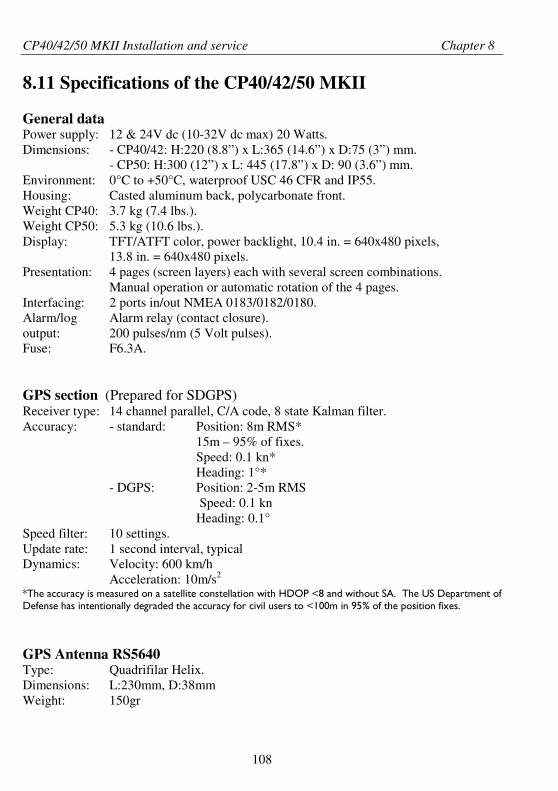
CP40/42/50 MKII Installation and service Chapter 8
108
8.11 Specifications of the CP40/42/50 MKII
General dataPower supply: 12 & 24V dc (10-32V dc max) 20 Watts.Dimensions: - CP40/42: H:220 (8.8”) x L:365 (14.6”) x D:75 (3”) mm.
- CP50: H:300 (12”) x L: 445 (17.8”) x D: 90 (3.6”) mm.Environment: 0°C to +50°C, waterproof USC 46 CFR and IP55.Housing: Casted aluminum back, polycarbonate front.Weight CP40: 3.7 kg (7.4 lbs.).Weight CP50: 5.3 kg (10.6 lbs.).Display: TFT/ATFT color, power backlight, 10.4 in. = 640x480 pixels,
13.8 in. = 640x480 pixels.Presentation: 4 pages (screen layers) each with several screen combinations.
Manual operation or automatic rotation of the 4 pages.Interfacing: 2 ports in/out NMEA 0183/0182/0180.Alarm/log Alarm relay (contact closure).output: 200 pulses/nm (5 Volt pulses).Fuse: F6.3A.
GPS section (Prepared for SDGPS)Receiver type: 14 channel parallel, C/A code, 8 state Kalman filter.Accuracy: - standard: Position: 8m RMS*
15m – 95% of fixes.Speed: 0.1 kn*Heading: 1°*
- DGPS: Position: 2-5m RMSSpeed: 0.1 kn
Heading: 0.1°Speed filter: 10 settings.Update rate: 1 second interval, typicalDynamics: Velocity: 600 km/h
Acceleration: 10m/s2
*The accuracy is measured on a satellite constellation with HDOP <8 and without SA. The US Department ofDefense has intentionally degraded the accuracy for civil users to <100m in 95% of the position fixes.
GPS Antenna RS5640Type: Quadrifilar Helix.Dimensions: L:230mm, D:38mmWeight: 150gr
CP40/42/50 MKII Installation and service Chapter 8
109
DGPS Antenna MGL-3Type: Patch (GPS) H-field (diff.).Dimensions: H:75mm, D:127mmWeight: 600gr
Environment: -35°C to +75°C, 95% rel.Mounting: 1” 14 thread (standard US).Cable: 10m RG58 (standard).
Max. 15m RG58 (option).Max. 30m RG213 (option).
Chartplotter sectionChart system: C-MAP NTPresentation: Two charts in different scales on screen simultaneously.
OptionsSunhoodSimrad DataCardsTL50 Turbo LoaderC-MAP electronic charts NT6-channel NMEA Buffer RS5345DS40/42 Dual station, 10” TFT/ATFT color or monochrome LCD screen.DS50 Dual station, 14” color LCD screen.

CP40/42/50 MKII Installation and service Chapter 8
110
CP40/42/50 MKII Glossary of terms Appendix A
111
Glossary of terms
Active display – is the display placed in the window with the highlighted frameon the screen. Only the active display on the screen is operable. Press the [WIN]key to toggle which display (window) should be the active one on the screen withthe highlighted frame. Switch between active displays (windows) as required.
Active window – is recognized by the window on the screen with the highlightedframe. A new active window can be selected via the menu, press [MENU] andtoggle active window by pressing [WIN] repeatedly, then select a new displayfrom one of the menus. The window you selected in the menu bar will now havethe highlighted frame and are therefore the new active window on the screen.
Almanac – a satellite’s almanac data, is data which determines an approximatelane for satellites in orbit. The almanac data is used by the GPS receiver to findand lock onto the satellite signal. The CPXX has a built-in basic almanac.
AVN – Approximate Velocity Necessary – to arrive at a specific waypoint at aspecific time.
Bearing – is the direction of where to go e.g. towards a specific waypoint.
Course – Course Over Ground, magnetic or true. The direction of which thevessel is moving.
dGPS – differential data is received from built-in DGPS module or an externalDGPS Receiver.
DGPS – the position is being corrected by differential data.
ETA – Estimated Time of Arrival – at a specific waypoint if keeping a steadyspeed.
Grid - on chart can be set to AUTO / ON / OFF.ON = the grid is always visible on the chart display.OFF = the grid is turned off and will not show on the chart display.AUTO = the grid will not appear in the ordinary chart display, but will be therewhen in overzoom and when “Chart” is turned off in the Chart setup, whichmeans that there will be no World chart presented and no C-MAP chartspresented – only user-made data such as waypoints, routes, lines and tracks, etc.
CP40/42/50 MKII Glossary of terms Appendix A
112
Great circle – the shortest distance on the globe.
Heading – the direction of which the vessel is pointing.
Interface – the connection between two pieces of equipment.
Lock cursors – will lock the cursors in two chart displays on the same screenand thus make the cursor movements synchronized. When moving the cursor tosearch for e.g. a harbor in one chart (large scale), the other chart (small scale)will automatically follow and thus reveal the details. This process is verydemanding and may take some seconds extra for updating.
LOG speed calibration – the unit is preset to receive 19000 pulses per nauticalmile from the log transducer (paddle wheel). However the figure might have tobe changed to compensate for various transducers and actual water flow passingthe transducer. The correct pulse rate is calculated by:
19000 x indicated speed (e.g. 4kn) = 15.200 pulses/nmactual speed (GPS) (e.g. 5kn)
Measurement units – the user may select the displayed units to be one of thefollowing: m meters
ft feet, 1 foot is 0.3048 metersfm fathoms, 1 fathom is 1.8288 metersnm nautical mile, 1 nm is 1,852 meterskn knots, nautical mile per hourkm kilometer, 1 km is 1,000 meterskh kilometer per hourmi statute mile, 1 mile is 1,609 metersmh mile per hour
MENU – the selection of main menus will be shown in the upper part of thescreen. Leaf through the menus by means of the cursor key and select thehighlighted menu by pressing the [ENT] key, or use the numerical keys toactivate one of the menus.
Navigation simulator - the chartplotter function features a built-in navigationsimulator which can be used for demonstration purpose or for practicing ‘live’navigation in ‘off season’.Navigation to cursor or waypoint, in route or in track is started as described in
CP40/42/50 MKII Glossary of terms Appendix A
113
chapter 6. The navigation simulator is started via the NMEA interface setup:Press [MENU],[6],[2]; go to ‘OFF’ next to ‘External position, course, speed:’and press the [+] zoom key twice to toggle to: Dead reck.; move cursor to theright and enter a speed value of e.g. 10 knots; press [ENT] twice.The ship symbol will now ‘sail’ to the point of destination directly or via theroute you have selected and you can see how the alarms and automatic waypointshift all work, as if you were sailing yourself. You can also simulate making atrack trailing the ship or plotting eventmarks, etc. as the ship is ‘sailing’.
NMEA – National Marine Electronics Association. The NMEA is anorganization of manufacturers of marine electronics equipment. They haveadopted the NMEA0183 as a standard for communications between various typesof marine electronic equipment.
Port side – left (red). Opposite to Starboard – right (green).
Release cursors – see “Lock cursors”.
Restart to approaching point – will automatic re-calculate the navigation datafrom current position to approaching point.
Rhumbline – is the straight line to a waypoint on a chart.
Route name – each route can be given a name for easy identification.
Speed – Speed Over Ground, measured in knots, kilometers, and miles.
Starboard side – right (green). Opposite to Port – left (red).
TFT display – Thin-Film Transistor (Active matrix).
Trackpoint advance – will automatically shift to the next trackpoint in the trackand provide new steering details (Track navigation).
UTC – Universal Time Coordinates, which is equal to standard time in London(GMT). UTC is not affected by the local summertime adjustments.
Velocity (VMG) – speed towards approaching waypoint.
CP40/42/50 MKII Glossary of terms Appendix A
114
Waypoint advance – will automatically shift to the next waypoint in the routeand provide new steering details (Route navigation).
Waypoint name – a name can be added to each waypoint for easy identification.
WPplot – instant storage of actual position as a waypoint.
XTE – Cross-Track-Error (-Distance), measured magnitude of the position errorperpendicular to the intended track.
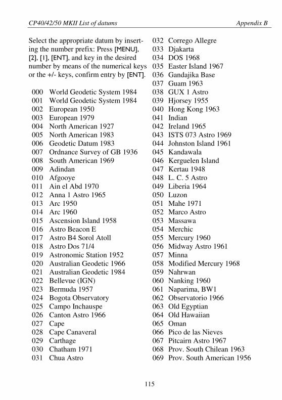
CP40/42/50 MKII List of datums Appendix B
115
032 Corrego Allegre033 Djakarta034 DOS 1968035 Easter Island 1967036 Gandajika Base
Select the appropriate datum by insert-ing the number prefix: Press [MENU],[2], [1], [ENT], and key in the desirednumber by means of the numerical keysor the +/- keys, confirm entry by [ENT].
037 Guam 1963000 World Geodetic System 1984 038 GUX 1 Astro001 World Geodetic System 1984 039 Hjorsey 1955002 European 1950 040 Hong Kong 1963003 European 1979 041 Indian004 North American 1927 042 Ireland 1965005 North American 1983 043 ISTS 073 Astro 1969006 Geodetic Datum 1983 044 Johnston Island 1961007 Ordnance Survey of GB 1936 045 Kandawala008 South American 1969 046 Kerguelen Island009 Adindan 047 Kertau 1948010 Afgooye 048 L. C. 5 Astro011 Ain el Abd 1970 049 Liberia 1964012 Anna 1 Astro 1965 050 Luzon013 Arc 1950 051 Mahe 1971014 Arc 1960 052 Marco Astro015 Ascension Island 1958 053 Massawa016 Astro Beacon E 054 Merchic017 Astro B4 Sorol Atoll 055 Mercury 1960018 Astro Dos 71/4 056 Midway Astro 1961019 Astronomic Station 1952 057 Minna020 Australian Geodetic 1966 058 Modified Mercury 1968021 Australian Geodetic 1984 059 Nahrwan022 Bellevue (IGN) 060 Nanking 1960023 Bermuda 1957 061 Naparima, BW1024 Bogota Observatory 062 Observatorio 1966025 Campo Inchauspe 063 Old Egyptian026 Canton Astro 1966 064 Old Hawaiian027 Cape 065 Oman028 Cape Canaveral 066 Pico de las Nieves029 Carthage 067 Pitcairn Astro 1967030 Chatham 1971 068 Prov. South Chilean 1963031 Chua Astro 069 Prov. South American 1956
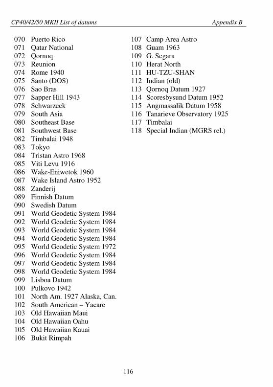
CP40/42/50 MKII List of datums Appendix B
116
070 Puerto Rico 107 Camp Area Astro071 Qatar National 108 Guam 1963072 Qornoq 109 G. Segara073 Reunion 110 Herat North074 Rome 1940 111 HU-TZU-SHAN075 Santo (DOS) 112 Indian (old)076 Sao Bras 113 Qornoq Datum 1927077 Sapper Hill 1943 114 Scoresbysund Datum 1952078 Schwarzeck 115 Angmassalik Datum 1958079 South Asia 116 Tanarieve Observatory 1925080 Southeast Base 117 Timbalai081 Southwest Base 118 Special Indian (MGRS rel.)082 Timbalai 1948083 Tokyo084 Tristan Astro 1968085 Viti Levu 1916086 Wake-Eniwetok 1960087 Wake Island Astro 1952088 Zanderij089 Finnish Datum090 Swedish Datum091 World Geodetic System 1984092 World Geodetic System 1984093 World Geodetic System 1984094 World Geodetic System 1984095 World Geodetic System 1972096 World Geodetic System 1984097 World Geodetic System 1984098 World Geodetic System 1984099 Lisboa Datum100 Pulkovo 1942101 North Am. 1927 Alaska, Can.102 South American – Yacare103 Old Hawaiian Maui104 Old Hawaiian Oahu105 Old Hawaiian Kauai106 Bukit Rimpah
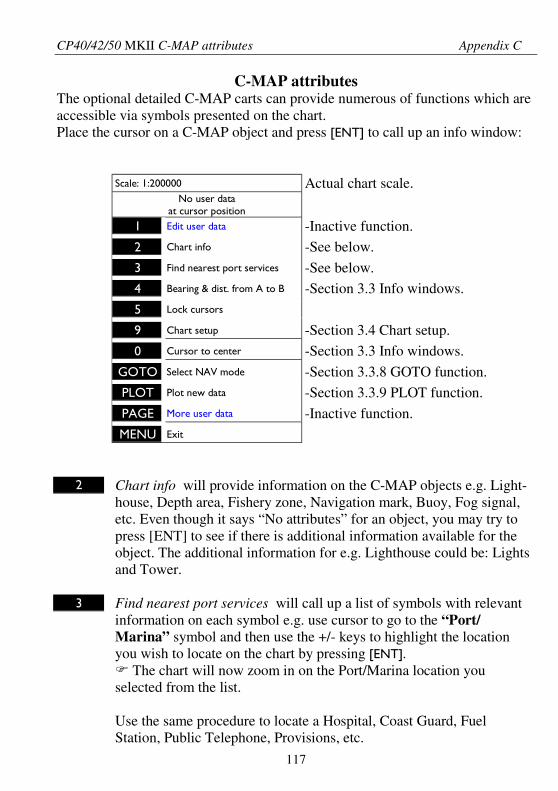
CP40/42/50 MKII C-MAP attributes Appendix C
117
C-MAP attributesThe optional detailed C-MAP carts can provide numerous of functions which areaccessible via symbols presented on the chart.Place the cursor on a C-MAP object and press [ENT] to call up an info window:
Scale: 1:200000 Actual chart scale.No user data
at cursor position
1 Edit user data -Inactive function.
2 Chart info -See below.
3 Find nearest port services -See below.4 Bearing & dist. from A to B -Section 3.3 Info windows.
5 Lock cursors
9 Chart setup -Section 3.4 Chart setup.
0 Cursor to center -Section 3.3 Info windows.
GOTO Select NAV mode -Section 3.3.8 GOTO function.PLOT Plot new data -Section 3.3.9 PLOT function.
PAGE More user data -Inactive function.MENU Exit
2 Chart info will provide information on the C-MAP objects e.g. Light-house, Depth area, Fishery zone, Navigation mark, Buoy, Fog signal,etc. Even though it says “No attributes” for an object, you may try topress [ENT] to see if there is additional information available for theobject. The additional information for e.g. Lighthouse could be: Lightsand Tower.
3 Find nearest port services will call up a list of symbols with relevantinformation on each symbol e.g. use cursor to go to the “Port/Marina” symbol and then use the +/- keys to highlight the locationyou wish to locate on the chart by pressing [ENT].
The chart will now zoom in on the Port/Marina location youselected from the list.
Use the same procedure to locate a Hospital, Coast Guard, FuelStation, Public Telephone, Provisions, etc.
CP40/42/50 MKII C-MAP attributes Appendix C
118
Tide information
To gain access to the tide information, you first have to located the tide symbol –a shape of a diamond with a T in the middle – on the chart. Place the cursor onthe symbol, and press [ENT].
The info window (see previous page) will appear on the screen. Press [2] Chartinfo to call up the Tide height information.
In most places there are two high and two low tides per day. The heights of thehigh tides, or the low tides, may not be the same. The height of the tide varieswith the time of year.
Object name is the location name of the Tide station.
Time zone: -1 indicates that the local time is 1 hour less than the standard timein London (GMT).
The low and high tides are shown for one day at a time. The 24-hour timeschedule will always run from 00 hours to 24 hours each day. The informationprovided will always be for the present day.
However, if you wish to see the low and high tides for a different date – in thepast or in the future – it is possible to change the date:
Day In the display there will be a red box cursor on the number of theday in the month. Toggle to a different number (date) with the +/-keys.
Month Use the cursor to go to the present month. Toggle to a differentmonth with the +/- keys.
Year Use the cursor to go to the year. Toggle to a different year with the+/- keys.
The last four lines in the Tide display will inform of Begin Twilight, Sunrise,Sunset and End Twilight for the present day.
CautionThe tide information system is quite accurate. However, the predictions are

CP40/42/50 MKII C-MAP attributes Appendix C
119
subject to variables, which, like the weather, are beyond the control of man.The tide predictions are based on normal weather conditions. Hurricanes andstrong winds will often have a strong influence on the water level, which canvary several meters.
Changes in a coast line, either due to natural erosion, major storms or larger man-made constructions, like breakwaters or dredged canals, can also have influenceon the local tide situation.
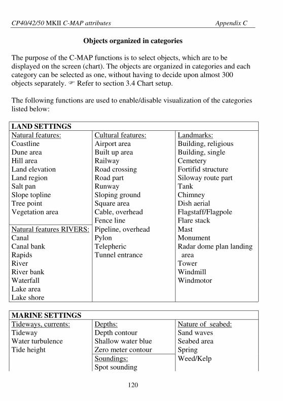
CP40/42/50 MKII C-MAP attributes Appendix C
120
Objects organized in categories
The purpose of the C-MAP functions is to select objects, which are to bedisplayed on the screen (chart). The objects are organized in categories and eachcategory can be selected as one, without having to decide upon almost 300objects separately. Refer to section 3.4 Chart setup.
The following functions are used to enable/disable visualization of the categorieslisted below:
LAND SETTINGSNatural features:CoastlineDune areaHill areaLand elevationLand regionSalt panSlope toplineTree pointVegetation area
Cultural features:Airport areaBuilt up areaRailwayRoad crossingRoad partRunwaySloping groundSquare areaCable, overheadFence line
Landmarks:Building, religiousBuilding, singleCemeteryFortifid structureSiloway route partTankChimneyDish aerialFlagstaff/FlagpoleFlare stack
Natural features RIVERS:CanalCanal bankRapidsRiverRiver bankWaterfallLake areaLake shore
Pipeline, overheadPylonTelephericTunnel entrance
MastMonumentRadar dome plan landingarea
TowerWindmillWindmotor
MARINE SETTINGSTideways, currents:TidewayWater turbulenceTide height
Depths:Depth contourShallow water blueZero meter contour
Nature of seabed:Sand wavesSeabed areaSpring
Soundings:Spot sounding
Weed/Kelp
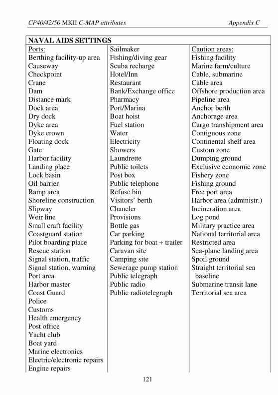
CP40/42/50 MKII C-MAP attributes Appendix C
121
NAVAL AIDS SETTINGSPorts:Berthing facility-up areaCausewayCheckpointCraneDamDistance markDock areaDry dockDyke areaDyke crownFloating dockGateHarbor facilityLanding placeLock basinOil barrierRamp areaShoreline constructionSlipwayWeir lineSmall craft facilityCoastguard stationPilot boarding placeRescue stationSignal station, trafficSignal station, warningPort areaHarbor masterCoast GuardPoliceCustomsHealth emergencyPost officeYacht clubBoat yardMarine electronicsElectric/electronic repairsEngine repairs
SailmakerFishing/diving gearScuba rechargeHotel/InnRestaurantBank/Exchange officePharmacyPort/MarinaBoat hoistFuel stationWaterElectricityShowersLaundrettePublic toiletsPost boxPublic telephoneRefuse binVisitors’ berthChanelerProvisionsBottle gasCar parkingParking for boat + trailerCaravan siteCamping siteSewerage pump stationPublic telegraphPublic radioPublic radiotelegraph
Caution areas:Fishing facilityMarine farm/cultureCable, submarineCable areaOffshore production areaPipeline areaAnchor berthAnchorage areaCargo transhipment areaContiguous zoneContinental shelf areaCustom zoneDumping groundExclusive economic zoneFishery zoneFishing groundFree port areaHarbor area (administr.)Incineration areaLog pondMilitary practice areaNational territorial areaRestricted areaSea-plane landing areaSpoil groundStraight territorial seabaseline
Submarine transit laneTerritorial sea area
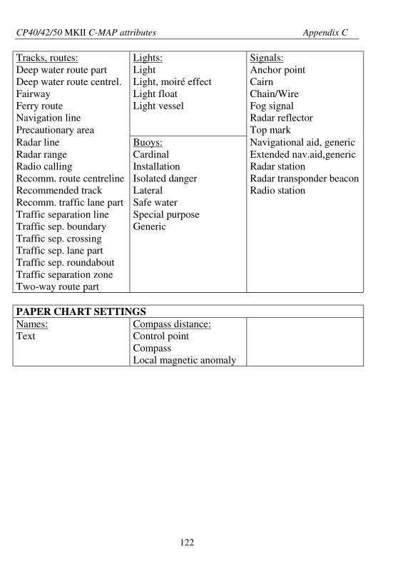
CP40/42/50 MKII C-MAP attributes Appendix C
122
Tracks, routes:Deep water route partDeep water route centrel.FairwayFerry routeNavigation linePrecautionary area
Lights:LightLight, moiré effectLight floatLight vessel
Signals:Anchor pointCairnChain/WireFog signalRadar reflectorTop mark
Radar lineRadar rangeRadio callingRecomm. route centrelineRecommended trackRecomm. traffic lane partTraffic separation lineTraffic sep. boundaryTraffic sep. crossingTraffic sep. lane partTraffic sep. roundaboutTraffic separation zoneTwo-way route part
Buoys:CardinalInstallationIsolated dangerLateralSafe waterSpecial purposeGeneric
Navigational aid, genericExtended nav.aid,genericRadar stationRadar transponder beaconRadio station
PAPER CHART SETTINGSNames:Text
Compass distance:Control pointCompassLocal magnetic anomaly
CP40/42/50 MKII DGPS Chartplotter Index
123
Active display 111Active window 7,111Agents end of manualAlarms,- anchor 66- reset 84- speed 83- WP-circle 66- WP-line 66- XTE 66,68,113Almanac 45,111Anchor guard 29,72Antenna,- altitude mode 38- installation 101
CE declaration 127Chart menu 17- auto chart select 32- built-in world chart 19- chart info 117- chart presets 93- chart scales 19- C-MAP attributes 32,117- color of ship/cursor symbol 92- depth levels 32- extended level range 32- find nearest port services 117- grid 32,111- lines on chart 32- lock/release cursors 22,112- orientation 32- rotation resolution 32- routes on chart 32- setup 32- show scale 32- targets on chart 32- tide information 118- tracks on chart 32- waypoints on chart 32
C-MAP,- attributes 117- cartridges 20
C-MAP - continued,- insertion/removal 20- port information 117- tide information 118
Combination displays 7Contrast and light settings 10Course and bearing 38Cursor function 18,22,23- cursor color 32- navigation 29,74
Data transfer via DataCard or disc 62Datum 35,37- list 115Daylight 92Dead reckoning 88,Decca lanes 90Delete memory 93Depth,-depth & temperature diagram 81- display depth in position display 38DGPS setup 47- external DGPS 48- list of beacon stations 47Display color 92DOP limit 46DSC alarm 49Dual station,- connection cable 99,100- operation 100
Echo menu 81Electrical connections,- external log/pos-status relay 102- external MOB switches 102- fuse 103- NMEA interface 103- optional 104- power supply 103
Factory settings 93
Global Positioning system 5
CP40/42/50 MKII DGPS Chartplotter Index
124
Glossary of terms 111GOTO function 29
HDOP limit 46
Info windows 22- bearing & dist. from A to B 22- chart info 117- chart setup 22- edit user data 22- find nearest port services 117- lock/release cursors 22- more user data 22- plot new data 22- select NAV mode 22- ship to center 22Initial start-up 15Installation,- antenna 101- CP40 95- CP50 97- DS40/50 99Interface setup, alarm/log 89Interface setup 85Introduction 5
Key functions 10Key symbols in the manual 6
Language 15,83Light and contrast settings 10Lines,- delete all lines 93- draw line 30- edit 25,57- linepoints 26- stored in the memory 56Local time and date 36Log 35- reset 37Log speed calibration 83,112Log speed sensor 83Loran C 91
Magnetic course 35Maintenance 105Master reset 94Measurement units 83,112Memory 93Menu bar 12- inactive functions 12Menu layout 13MOB function back of front cover- external switches 102- navigation 71- position 44
Naming of routes, points, etc. 14Navigation,- advance 29,71- arrival time 55- auto waypoint shift 67- composite 67- display 65,68- ETA & AVN display 69- examples 73- Great Circle 67,112- highway 68- orientation: HEAD UP 33 NAV UP 33 NORTH UP 33- restart to approaching point 29,113- Rhumbline 53,67- set & drift 39- set & drift trim display 69- setup 66- simulator 88,112- time to go from A to B 55- total distance from A to B 55- turn NAV off 29,69NAV menu,- NAV active 67- NAV inactive 65NAV modes,- anchor guard 29,72- cursor 29,74- navigation examples 73
CP40/42/50 MKII DGPS Chartplotter Index
125
NAV modes - continued,- route 29,76- track 29,78- waypoint 29,75Nightlight 92
PAGE system 7- preset pages 8- rotation interval 83Palette setup 92PDOP limit 46PLOT function 30- plot new data 30Port services on chart 117Position menu 35- decca lanes 38,90- display 35- latitude/longitude 38- loran C 38,91- setup 37- start position 38Power off 16Power on 15
Quick guide 10
Repair and service 106Routes,- calculation 55- course line 53- delete all routes 93- delete via menu 54- direction in route 53- edit 25,53- make route 30- stored in the memory 52- menu 51- navigation 29,74- routepoints 26- show route as NAVIGATION 54- show route as POINTS 54
Safety summary 6Satellite status 45
Set & drift 39Set & drift trim display 71Ship symbol 18- color 32Software version 83Spare parts 106Special menu 83Specifications 108Speed,- alarm 83- average 42- diagram 40- display speed as 38- dual speed display 41- filter level 38- indicator 42- over ground 35,40- setup 83- through water 40,42Status indicator and accuracy 36Symbols 14
Targets,- delete all targets 93- delete via menu 61- edit via chart 28- plot cursor position as target 30- stored in the memory 60Tide information on chart 118TL50 version 83Tracks,- auto trackpoint shift in track 66,79- delete all tracks 93- delete via menu 60- edit via chart 27- delete points from A to B 27- function 58- navigation 29,78- start track 58- stop track 59- stored in the memory 59- trackpoints 27- with TL50 Turbo Loader 58Troubleshooting 107
CP40/42/50 MKII DGPS Chartplotter Index
126
True course 35
UTC time 36
Velocity towards waypoint 40
Warranty 129Waypoints,- auto waypoint shift in route 66- delete all waypoints 93- delete via menu 52- edit via chart 24- list 51- menu 51- move to ship’s position 51- navigation 29,75- plot waypoint 30Wind display 42WINdow system 7- inactive functions 12
Zoom function 19- over-zoom function 19
Simrad Shipmate ASØstre Allé 6DK-9530 StøvringDenmark
John LarsenExcecutive Vice President
Simrad Shipmate AS
Declaration of Conformity
The EMC Directive, Article 10 (1)
Undersigned are herewith declaring, that
Product: SIMRAD CP40/42DGPS Chartplotter
is in accordance with the protection requirements in
the EMC Directive 89/336/EØF of May 3rd, 1989
Employed harmonized standards:
EN 60945:1993 / Amd.1:1993
Støvring February 15, 2001
Simrad Shipmate ASØstre Allé 6DK-9530 StøvringDenmark
John LarsenExcecutive Vice President
Simrad Shipmate AS
Declaration of Conformity
The EMC Directive, Article 10 (1)
Undersigned are herewith declaring, that
Product: SIMRAD CP50DGPS Chartplotter
is in accordance with the protection requirements in
the EMC Directive 89/336/EØF of May 3rd, 1989
Employed harmonized standards:
EN 60945:1993 / Amd.1:1993
Støvring February 15, 2001
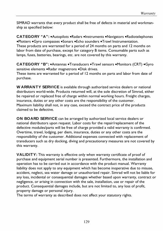
Warranty
129
SIMRAD warrants that every product shall be free of defects in material and workman-ship as specified below:
CATEGORY “A”: •Autopilots •Radars •Instruments •Navigators •Radiotelephones•Plotters •Gyro compasses •Sonars •Echo sounders •Trawl Instrumentation.These products are warranted for a period of 24 months on parts and 12 months onlabor from date of purchase, except for category B items. Consumable parts such aslamps, fuses, batteries, bearings, etc. are not covered by this warranty.
CATEGORY “B”: •Antennas •Transducers •Trawl sensors •Monitors (CRT) •Gyrosensitive elements •Radar magnetrons •Disk drives.These items are warranted for a period of 12 months on parts and labor from date ofpurchase.
WARRANTY SERVICE is available through authorized service dealers or nationaldistributors world-wide. Products returned will, at the sole discretion of Simrad, eitherbe repaired or replaced free of charge within normal working hours. Freight charges,insurance, duties or any other costs are the responsibility of the customer.Maximum liability shall not, in any case, exceed the contract price of the productsclaimed to be defective.
ON BOARD SERVICE can be arranged by authorized local service dealers ornational distributors upon request. Labor costs for the repair/replacement of thedefective modules/parts will be free of charge provided a valid warranty is confirmed.Overtime, travel, lodging, per diem, insurance, duties or any other costs are theresponsibility of the customer. Additional expenses connected with replacement oftransducers such as dry docking, diving and precautionary measures are not covered bythis warranty.
VALIDITY: This warranty is effective only when warranty certificate of proof ofpurchase and equipment serial number is presented. Furthermore, the installation andoperation has to be carried out in accordance with the product manual. Warrantyliability does not apply to any equipment which has become inoperative due to misuse,accident, neglect, sea water damage or unauthorized repair. Simrad will not be liable forany loss, incidental or consequential damages whether based upon warranty, contract ornegligence, or arising in connection with the sale, installation, use or repair of theproduct. Consequential damages include, but are not limited to, any loss of profit,property damage or personal injury.The terms of warranty as described does not affect your statutory rights.
WA
RR
AN
TY
CA
RD
TO
BE
RE
TA
INE
DB
YT
HE
OW
NE
R
____
____
____
____
____
____
____
____
____
____
____
___
____
____
____
____
____
____
____
____
____
____
_O
WN
ER
VE
SS
EL
____
____
____
____
____
____
____
____
____
____
____
___
____
____
____
____
____
____
____
____
____
____
_A
DD
RE
SS
HO
ME
PO
RT
____
____
____
____
____
____
____
____
____
____
___
TY
PE
____
____
____
____
____
____
____
____
____
____
____
____
____
____
__E
QU
IPM
EN
T__
____
____
____
____
____
____
____
____
____
____
____
____
____
____
____
____
____
__
____
____
____
____
____
____
____
____
____
____
____
____
____
____
____
____
____
____
____
____
____
____
____
____
____
____
____
____
____
____
YE
S:_
____
___
NO
:___
____
_D
AT
EO
FP
UR
CH
AS
ED
AT
EO
FIN
ST
AL
LA
TIO
NIN
ST
RU
CT
ION
FO
RU
SE
GIV
EN
___________________________________________
AU
TH
OR
IZE
DIN
ST
AL
LE
R/D
EA
LE
RS
TA
MP
Sim
rad
Shi
pmat
eA
SØ
stre
Allé
6D
K-9
530
Stø
vrin
gD
enm
ark
SE
RIA
LN
O.
SIM
RA
Dw
arra
nts
that
ever
ypr
oduc
tsh
allb
efr
eeof
defe
cts
inm
ater
iala
ndw
orkm
ansh
ipas
spec
ifie
dov
erle
af:
tear
out
WA
RR
AN
TY
CA
RD
To
bem
aile
dto
the
NA
TIO
NA
LD
IST
RIB
UT
OR
(see
over
leaf
)to
geth
erw
ith
the
inst
alla
tion
repo
rtW
ITH
IN14
DA
YS
from
the
date
ofin
stal
lati
on.
____
____
____
____
____
____
____
____
____
____
____
___
____
____
____
____
____
____
____
____
____
____
_O
WN
ER
VE
SS
EL
____
____
____
____
____
____
____
____
____
____
____
___
____
____
____
____
____
____
____
____
____
____
_A
DD
RE
SS
HO
ME
PO
RT
____
____
____
____
____
____
____
____
____
____
____
___
____
____
____
____
____
____
____
____
____
____
_T
YP
E
____
____
____
____
____
____
____
____
____
____
____
____
____
____
__E
QU
IPM
EN
T__
____
____
____
____
____
____
____
____
____
____
____
____
____
____
____
____
____
__
____
____
____
____
____
____
____
____
____
____
____
____
____
____
____
____
____
____
____
____
____
____
____
____
____
____
____
____
____
____
____
____
____
____
____
____
____
____
DA
TE
OF
PU
RC
HA
SE
DA
TE
OF
INS
TA
LL
AT
ION
____
____
____
____
____
____
____
____
____
____
____
____
____
____
____
____
____
____
____
____
(CU
STO
ME
R’S
SIG
NA
TU
RE
)(D
EA
LE
R’S
SIG
NA
TU
RE
)
Sim
rad
Shi
pmat
eA
SØ
stre
All
é6
DK
-953
0S
tøvr
ing
Den
mar
k
SE
RIA
LN
O.

NA
TIO
NA
LS
IMR
AD
DIS
TR
IBU
TO
R:
____
____
____
____
____
____
____
____
____
____
____
____
____
____
____
____
____
____
_
____
____
____
____
____
____
____
____
____
____
____
____
____
____
____
____
____
____
_
____
____
____
____
____
____
____
____
____
____
____
____
____
____
____
____
____
____
_
____
____
____
____
____
____
____
____
____
____
____
____
____
____
____
____
____
____
_
ST
AM
PH
ER
E