Embed Size (px)
Citation preview
Simplify CAN bus implementations with chokeless transceivers
Maxwell RobertsonApplications Manager
Industrial Interface groupTexas Instruments
2 Simplify CAN bus implementations with chokeless transceivers April 2016
Chokeless CAN transceivers allow system designers to reduce size, cost, and complexity of CAN bus implementations while meeting stringent automotive EMC requirements.
With the density of electronics in automobiles increasing each year, it is important to ensure that in-vehicle networks maintain a high level of performance with respect to electromagnetic compatibility (EMC). This ensures that various sub-systems will continue to function as intended when integrated into a larger solution and operated in a typical (noisy) environment. Although there are many different in-vehicle networking standards and a variety of different EMC requirements from automotive original equipment manufacturers (OEMs), this paper focuses on a topic that has proved to be particularly challenging: radio frequency (RF) emissions from a controller area network (CAN) bus.
CAN uses balanced, differential signaling in order
to send binary data at baud rates of up to 1 Mbps
(or higher, if the “flexible data rate” variant is used).
Ideally, using differential signaling prevents the
external coupling of any noise. Since each half of
the differential pair (referred to as CANH and CANL)
vary symmetrically, noise contributions of each will
destructively interfere. However, no CAN transceiver
is perfectly ideal, and small asymmetries between
the CANH and CANL signals can give rise to a
differential signal that is not perfectly balanced.
When this occurs, the common-mode component
of the CAN signal (the average of both CANH
and CANL) will no longer be a constant DC value.
Instead, it will exhibit data-dependent noise.
Two primary types of imbalance can lead to this
noise. One is a mismatch between the steady-state
common-mode voltage levels that occur during the
dominant (driven) and recessive (high-impedance)
states. Another is a difference in the timing between
CANH and CANL signals as they transition between
these two states.
The steady-state mismatch results in a noise pattern
that resembles a scaled version of the CAN data
itself. This noise pattern is broad in its frequency
content, appearing as a series of evenly-spaced
discrete spectral lines that extend down to very low
frequencies. The timing mismatch results in a noise
pattern consisting of short pulses or disturbances
that occur whenever there is an edge transition in
the data. This noise pattern tends to have spectral
content primarily at higher frequencies.
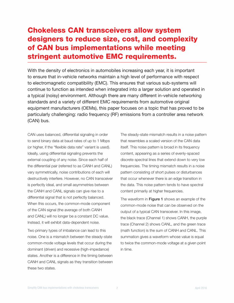
The waveform in Figure 1 shows an example of the
common-mode noise that can be observed on the
output of a typical CAN transceiver. In this image,
the black trace (Channel 1) shows CANH, the purple
trace (Channel 2) shows CANL, and the green trace
(math function) is the sum of CANH and CANL. This
summation gives a waveform whose value is equal
to twice the common-mode voltage at a given point
in time.
3 Simplify CAN bus implementations with chokeless transceivers April 2016
The common-mode waveform shows both types
of noise: high-frequency noise corresponding to
dominant-to-recessive/recessive-to-dominant
transitions, and low-frequency noise corresponding
to mismatched dominant and recessive
common modes.
Since the common-mode portion of the signal
can couple (through radiated or conducted paths)
onto other components in a system (or to external
systems), this common-mode noise directly impacts
emissions performance. The conducted emissions
of this device, which are measured per Engineering
Services for Industrial Electrical Engineering/
Electronics (IBEE) Zwickau methodology, are plotted
along with a common automotive original equipment
manufacturer (OEM) limit line in Figure 2.
The transceiver’s output emissions exceed the OEM
requirements in both low-frequency and
high-frequency regions. In order to lower the
emissions to a satisfactory level, some external
filtering must be used.
The most commonly-used filter component in CAN
buses is a common-mode choke (as shown in
Figure 3). A common-mode choke is constructed
out of two coils of wire that share a common core.
The direction of each coil’s windings is arranged
such that common-mode currents (that is, currents
flowing in the same direction through each coil)
have magnetic fluxes that share the same polarity.
This allows for the choke to act as an inductor for
common-mode signals, giving an impedance that
increases with increasing frequency. Conversely,
differential-mode currents (that is, currents flowing in
opposite directions through each coil) will have their
magnetic fluxes interact with opposite polarities.
For a balanced waveform like a CAN signal, the
opposing magnetic fluxes from each coil will be
equal in magnitude and therefore no net flux will
accumulate in the core. This results in the choke
acting as a short circuit for the CAN signals.
This technique can be very effective in reducing the
emissions of a CAN bus. For example, when the
above device that was shown to be failing emissions
requirements was re-tested with a 51-µH common-
mode choke the performance improved significantly
(Figure 4).
Figure 2: Conducted emissions of a typical CAN transceiver
-40
-30
-20
-10
0
10
20
30
40
50
60
70
0.1 1 10 100 1000
Con
duct
ed N
oise
(dB
µV)
Frequency (MHz)
Figure 3: Common mode choke schematic
Figure 1: Typical CAN transceiver CANH/CANL outputs and common-mode noise
TXD
RXD
5V
1
100nF
0
VIO
2
3
4
8
7
6
5
TXD
GND
VCC
RXD
STB
CANH
CANL
VIO
0
120CANH
CANL
4 Simplify CAN bus implementations with chokeless transceivers April 2016
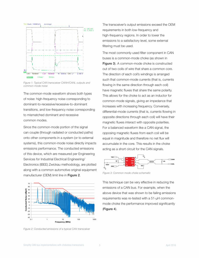
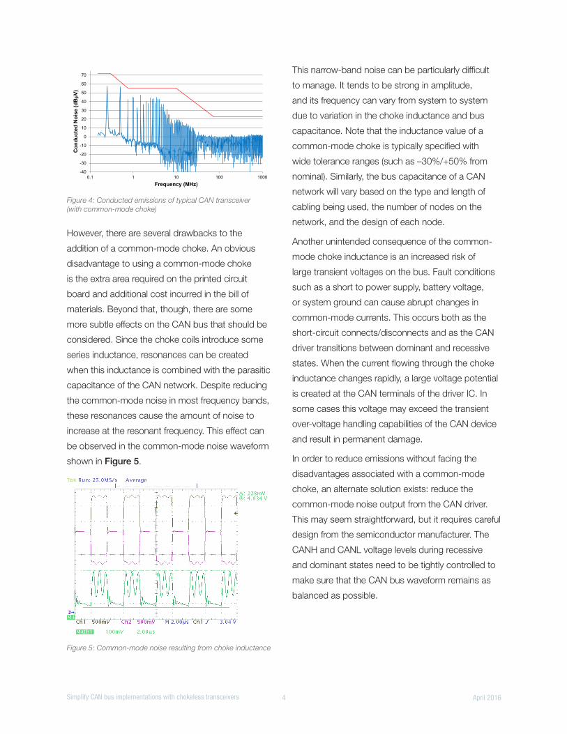
However, there are several drawbacks to the
addition of a common-mode choke. An obvious
disadvantage to using a common-mode choke
is the extra area required on the printed circuit
board and additional cost incurred in the bill of
materials. Beyond that, though, there are some
more subtle effects on the CAN bus that should be
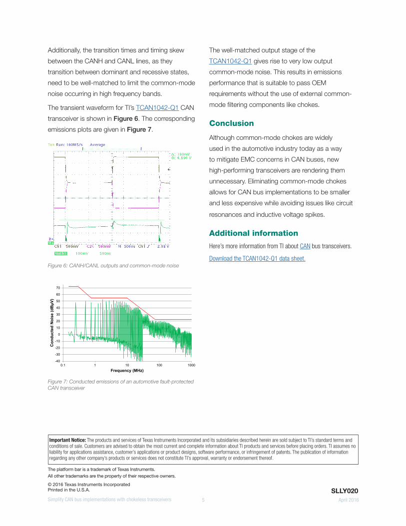
considered. Since the choke coils introduce some
series inductance, resonances can be created
when this inductance is combined with the parasitic
capacitance of the CAN network. Despite reducing
the common-mode noise in most frequency bands,
these resonances cause the amount of noise to
increase at the resonant frequency. This effect can
be observed in the common-mode noise waveform
shown in Figure 5.
This narrow-band noise can be particularly difficult
to manage. It tends to be strong in amplitude,
and its frequency can vary from system to system
due to variation in the choke inductance and bus
capacitance. Note that the inductance value of a
common-mode choke is typically specified with
wide tolerance ranges (such as –30%/+50% from
nominal). Similarly, the bus capacitance of a CAN
network will vary based on the type and length of
cabling being used, the number of nodes on the
network, and the design of each node.
Another unintended consequence of the common-
mode choke inductance is an increased risk of
large transient voltages on the bus. Fault conditions
such as a short to power supply, battery voltage,
or system ground can cause abrupt changes in
common-mode currents. This occurs both as the
short-circuit connects/disconnects and as the CAN
driver transitions between dominant and recessive
states. When the current flowing through the choke
inductance changes rapidly, a large voltage potential
is created at the CAN terminals of the driver IC. In
some cases this voltage may exceed the transient
over-voltage handling capabilities of the CAN device
and result in permanent damage.
In order to reduce emissions without facing the
disadvantages associated with a common-mode
choke, an alternate solution exists: reduce the
common-mode noise output from the CAN driver.
This may seem straightforward, but it requires careful
design from the semiconductor manufacturer. The
CANH and CANL voltage levels during recessive
and dominant states need to be tightly controlled to
make sure that the CAN bus waveform remains as
balanced as possible.
Figure 5: Common-mode noise resulting from choke inductance
Figure 4: Conducted emissions of typical CAN transceiver (with common-mode choke)
-40
-30
-20
-10
0
10
20
30
40
50
60
70
0.1 1 10 100 1000
Con
duct
ed N
oise
(dB
µV)
Frequency (MHz)
5 Simplify CAN bus implementations with chokeless transceivers April 2016
The platform bar is a trademark of Texas Instruments. All other trademarks are the property of their respective owners.
© 2016 Texas Instruments IncorporatedPrinted in the U.S.A.
Important Notice: The products and services of Texas Instruments Incorporated and its subsidiaries described herein are sold subject to TI’s standard terms and conditions of sale. Customers are advised to obtain the most current and complete information about TI products and services before placing orders. TI assumes no liability for applications assistance, customer’s applications or product designs, software performance, or infringement of patents. The publication of information regarding any other company’s products or services does not constitute TI’s approval, warranty or endorsement thereof.
Additionally, the transition times and timing skew
between the CANH and CANL lines, as they
transition between dominant and recessive states,
need to be well-matched to limit the common-mode
noise occurring in high frequency bands.
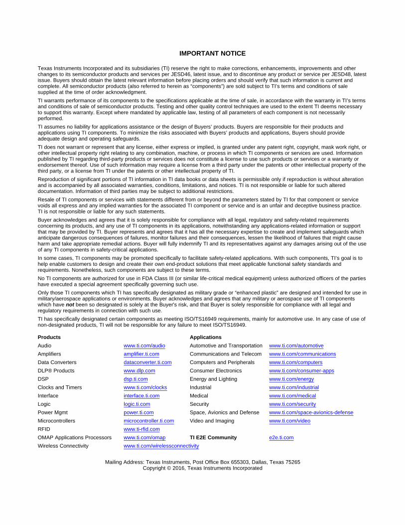
The transient waveform for TI’s TCAN1042-Q1 CAN
transceiver is shown in Figure 6. The corresponding
emissions plots are given in Figure 7.
The well-matched output stage of the
TCAN1042-Q1 gives rise to very low output
common-mode noise. This results in emissions
performance that is suitable to pass OEM
requirements without the use of external common-
mode filtering components like chokes.
Conclusion
Although common-mode chokes are widely
used in the automotive industry today as a way
to mitigate EMC concerns in CAN buses, new
high-performing transceivers are rendering them
unnecessary. Eliminating common-mode chokes
allows for CAN bus implementations to be smaller
and less expensive while avoiding issues like circuit
resonances and inductive voltage spikes.
Additional information
Here’s more information from TI about CAN bus transceivers.
Download the TCAN1042-Q1 data sheet.
SLLY020
Figure 7: Conducted emissions of an automotive fault-protected CAN transceiver
-40
-30
-20
-10
0
10
20
30
40
50
60
70
0.1 1 10 100 1000
Con
duct
ed N
oise
(dB
µV)
Frequency (MHz)
Figure 6: CANH/CANL outputs and common-mode noise
IMPORTANT NOTICE
Texas Instruments Incorporated and its subsidiaries (TI) reserve the right to make corrections, enhancements, improvements and otherchanges to its semiconductor products and services per JESD46, latest issue, and to discontinue any product or service per JESD48, latestissue. Buyers should obtain the latest relevant information before placing orders and should verify that such information is current andcomplete. All semiconductor products (also referred to herein as “components”) are sold subject to TI’s terms and conditions of salesupplied at the time of order acknowledgment.TI warrants performance of its components to the specifications applicable at the time of sale, in accordance with the warranty in TI’s termsand conditions of sale of semiconductor products. Testing and other quality control techniques are used to the extent TI deems necessaryto support this warranty. Except where mandated by applicable law, testing of all parameters of each component is not necessarilyperformed.TI assumes no liability for applications assistance or the design of Buyers’ products. Buyers are responsible for their products andapplications using TI components. To minimize the risks associated with Buyers’ products and applications, Buyers should provideadequate design and operating safeguards.TI does not warrant or represent that any license, either express or implied, is granted under any patent right, copyright, mask work right, orother intellectual property right relating to any combination, machine, or process in which TI components or services are used. Informationpublished by TI regarding third-party products or services does not constitute a license to use such products or services or a warranty orendorsement thereof. Use of such information may require a license from a third party under the patents or other intellectual property of thethird party, or a license from TI under the patents or other intellectual property of TI.Reproduction of significant portions of TI information in TI data books or data sheets is permissible only if reproduction is without alterationand is accompanied by all associated warranties, conditions, limitations, and notices. TI is not responsible or liable for such altereddocumentation. Information of third parties may be subject to additional restrictions.Resale of TI components or services with statements different from or beyond the parameters stated by TI for that component or servicevoids all express and any implied warranties for the associated TI component or service and is an unfair and deceptive business practice.TI is not responsible or liable for any such statements.Buyer acknowledges and agrees that it is solely responsible for compliance with all legal, regulatory and safety-related requirementsconcerning its products, and any use of TI components in its applications, notwithstanding any applications-related information or supportthat may be provided by TI. Buyer represents and agrees that it has all the necessary expertise to create and implement safeguards whichanticipate dangerous consequences of failures, monitor failures and their consequences, lessen the likelihood of failures that might causeharm and take appropriate remedial actions. Buyer will fully indemnify TI and its representatives against any damages arising out of the useof any TI components in safety-critical applications.In some cases, TI components may be promoted specifically to facilitate safety-related applications. With such components, TI’s goal is tohelp enable customers to design and create their own end-product solutions that meet applicable functional safety standards andrequirements. Nonetheless, such components are subject to these terms.No TI components are authorized for use in FDA Class III (or similar life-critical medical equipment) unless authorized officers of the partieshave executed a special agreement specifically governing such use.Only those TI components which TI has specifically designated as military grade or “enhanced plastic” are designed and intended for use inmilitary/aerospace applications or environments. Buyer acknowledges and agrees that any military or aerospace use of TI componentswhich have not been so designated is solely at the Buyer's risk, and that Buyer is solely responsible for compliance with all legal andregulatory requirements in connection with such use.TI has specifically designated certain components as meeting ISO/TS16949 requirements, mainly for automotive use. In any case of use ofnon-designated products, TI will not be responsible for any failure to meet ISO/TS16949.
Products ApplicationsAudio www.ti.com/audio Automotive and Transportation www.ti.com/automotiveAmplifiers amplifier.ti.com Communications and Telecom www.ti.com/communicationsData Converters dataconverter.ti.com Computers and Peripherals www.ti.com/computersDLP® Products www.dlp.com Consumer Electronics www.ti.com/consumer-appsDSP dsp.ti.com Energy and Lighting www.ti.com/energyClocks and Timers www.ti.com/clocks Industrial www.ti.com/industrialInterface interface.ti.com Medical www.ti.com/medicalLogic logic.ti.com Security www.ti.com/securityPower Mgmt power.ti.com Space, Avionics and Defense www.ti.com/space-avionics-defenseMicrocontrollers microcontroller.ti.com Video and Imaging www.ti.com/videoRFID www.ti-rfid.comOMAP Applications Processors www.ti.com/omap TI E2E Community e2e.ti.comWireless Connectivity www.ti.com/wirelessconnectivity
Mailing Address: Texas Instruments, Post Office Box 655303, Dallas, Texas 75265Copyright © 2016, Texas Instruments Incorporated