Embed Size (px)
Citation preview
SIMPLIFIED ENGINEERmG GRAPHICS/ AND
THE APPLICATION TO INDUSTRY
By
John Douglas Wilhoit, Jr. I\
Bachelor of Science
Oklahoma State University
Stillwater, Oklahoma
196o
Submitted. to the faculty of the Graduate School of the Okl.aha:ia State University
in p:irtial :f'ul:fillm.ent of the requirements for the degree of MASTER OF SCIENCE
August, 1962
SI -!PL!FIED ENGilfll!&RING GRAPHICS AND
THE APPLICATION TO nrotJSTRY
Associate Professor Read, Departm.ont of Tro.de and Industrial ucatio.n.
Dean of the Graduate School Oklahooa State University
50532l ii
OKLAHOMA STATE UN!VERSI . t
LIBRARY
NOV 13 1962
PREFACE
t'Si.I!l.plified Engineering Graphics and The Application to Industry"
offers a comprehensive study toward an economical method of reducing
drafting cost in industry. The material illustrates methods for solving
graphical problems based UJ?Oil the principles of orthographic projection.
The :material for this thesis has been organized With the full
understanding that all industry has a different viewpoint on simplified
drawing and that little has been accomplished toward standardization of
simplified practices. The ,triter f eels that an intelligent solution to
this problem is of vital necessity and offers the following material
as ~rtial fulfillment to that solution.
The objective is to determine and prove that industry and
technology is ready for simplified engineering graphics and to establish
the necessity for the Anerican Standards Association and the Military
Standards 1>epart!lent to issue standardization bulletins on simplified
engineering graphics.
The writer of this study vTishes to express his appreciation to l_
Professor T. Pete Chapaan, thesis advisor, and Dr. Roy Dugger, United
States Office of Education, for their valuable assistance in the planniI{!;
and completion of this thesis; also to Mr. Joe Ables, Oklahoma State
Supervisor of Technical Training Service, for his advice and suggestions,
and to those in industry who so graciously furnished information for
this study.
Grateful acknowledgement is also made to r:ry pa.rents whose
self-sacrifice made possible the education upon which this thesis is based. iii

&'ratitud.e is extend.ea to nry wife, Rose Marie Wilhoit, to ny
o.au.gb:ter Terry Lyim Wilhoit, and to my son John D. Wilhoit, for their
tolerance, inspiration and encourage~ent throughout the preparation
of' this thesis.
iv
TABIB OF CONTENTS
Chapter
I.
II.
III.
INTRODUCTION . . . • • • • . . . . . . . . . . . . . . . . 1. The Problem Stated • • . . . • • . • • • 2. Purpose of the Study • . . • . • . • . . • • • 3. Need for the Study . . . . . • . • • • . • 4. Extent of the Study • • • . . • . • • . • . • . . .
MULTIVIEW ffi()J]X!TION •• . . . . . . . . . . . . . . . . . l. 2. 3. 4.
Technical Drawing • • • • • • • • • • • • • • • • • Basic Dimensions • • • • • • • • • • • • • • •
• • Conventional Method of Multiview Projection Drafting Objectives • • • • • • • • • • • • • • • •
SIMPLIFIED DRAWING PRACTICES . . . . . . . . . . . . . . . 1 • . 2. 3. 4. 5. 6. 7. 8. 9.
J.O. 11. 12.
Drafting Standards • • • • • • • • • • • • • • • • Acceptance of Simplification ••••••••••• Standard Practices of Simplified Drawing •• Simplified Drafting Applied •••••••••••• Superfluous Views • • • • • • • • • • Elaborate Pictorials • • • • • • • • • •• Synbolic Drawing • • • • • • • • • • • • • • • • • Note Description • • • • • • • •••• Mechanical Drafting Aids ••••••••••••• Te:mpla tes • • • • • • • • • • • • • • • • • • • Coo.plexi ty • • • • • • • • • • • • • • • • Dimension.mg • • • • • • • • • • • • • • . • • • •
IV. PHOTODRAWING • • • • . . . . . . . . . . . . . . . . . l. 2.
Photodrawing as a Form of Simplification ?vlicrofilm. • • • • • • • • • • • • • . • •
• • . . . • • . . .
1
l 2 4 5
7
7 9
12 14
16
16 16 17 18 20 20 23 27 28 30 34 38
42
42 45
V. smMARY, CONCLUSIONS AND RECOMMENDATIONS • • • • • • • • • 46
1. 2. 3.
BIBLIOORAPHY
APPENDICES
Problem Summarized • • Conclusion ••••• Reccnm.endations • •
V
. . . . . . . . . . . . . . . . . . . . . . . . . . . . . . . . . . . . 46 47 55
58
6o
Table
I . II .
III. r.v. v.
VI . VII .
VIII.
Figure
l. 2 . 3. 4. 5. 6. 7. 8 . 9.
10. 11. l2. 13. 15.
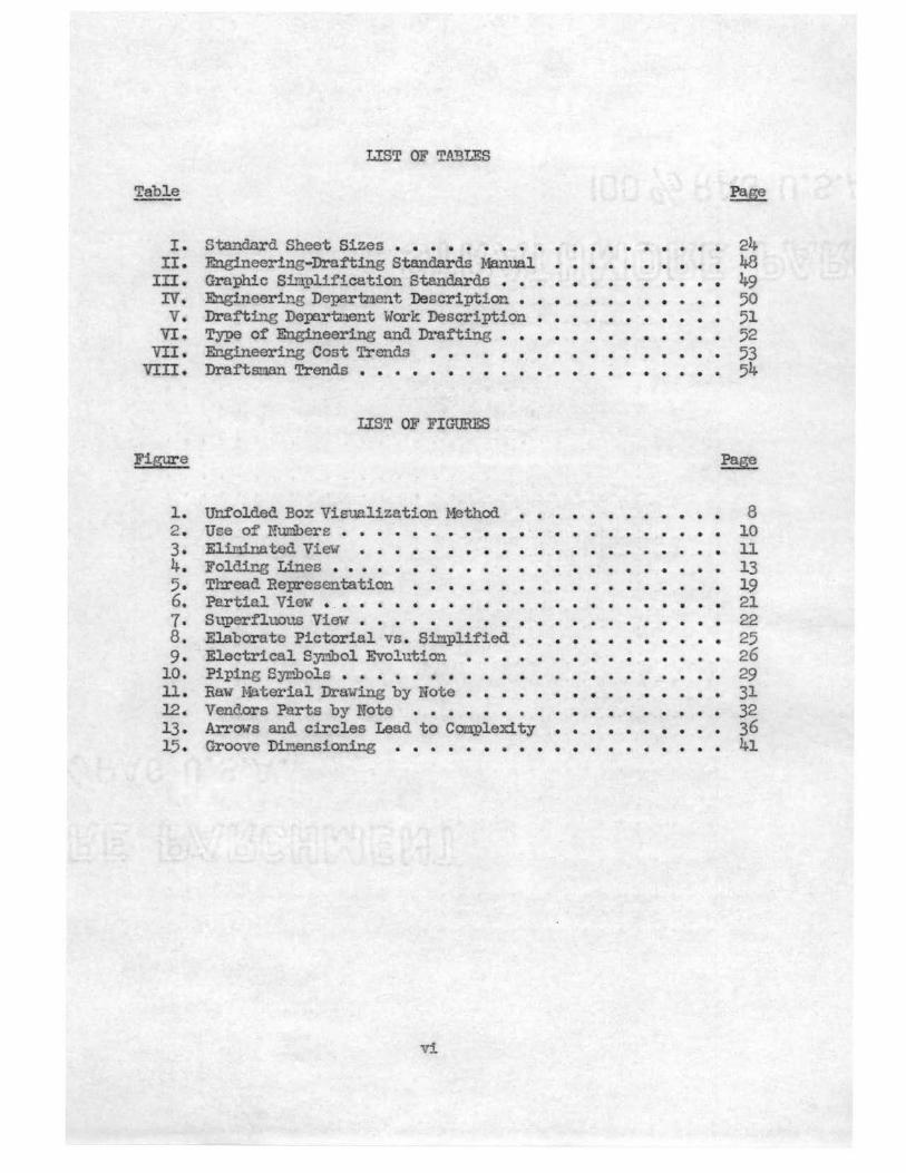
L.!ST OF TA3LES
Standard Sheet Sizes • • • • • • • • • • • • • • • • • • • Engineering-Drafting Standards Manual •••••••••• Graphic Simplification Standar ds ••••••••••••• Engineering Department Description •••••••••• Drafting Dern.rtuent Work Description • • • • • • • • • • • Type of Engineering and Drafting • • • • • • • • • • • Engineering Cost Trends • • • • • • • • • • • Draf'tsman Trends • • • • • • • • • • • • • • • • • • • • •
LIST OF FIGURES
Ur...:f olded Boz Visualization Method. . . . . . . . . . . . . Use of Numbers • • • • • • • .. • • • • • • • • Elininated Vie ••••••••••••••• • • Folding Lines • . . . . • . • • . • . . . • • . • • • . • • Thread Representation • • • • • • • • • • • • Partial View- • . . . • • • • • . . . . • • • . • • • • • Superfluous View • • • • • • • • • • • • • • El.aborate Pictorial vs . Simplified •••••••••••• Electrical Synbol Evolution ••••••••••••• Piping Syr,..bols • • • • • • • • • • • • • • • • • • • • • • Raw Material Dra; · in.g by Note • • • • • • • • • • • • • Vendors Parts by Note • • • • • • • • • Arrows and circles Lead to Complexity •••••••••• Groove Dime:rlsioning • • • • • • • • • • • • • • • • • • •
vi
24 48 49 50 51 52 53 54
8 10 11 13 19 21 22 25 26 29 31 32 36 41
CIIAPrER I
INTRODUCTION
Engineering drawing as we know it today is a graphic language used
by draftsnen and enemeers to convey a description as to the size and
shape of an object. Certain standards are to be maintained by the
draftsman and engineer while performing his drawing task . 1 An
understanding of the theory of projection and dimensioning is essential,
and he must be f'aru.liar with the standards described by the Atierican
Standards and Mill tary Standards publications .
I -1. The Problel!l Stated . The increasing demnd of industry
for the highly skilled technical draftsman has been brought about by
an engineering change. No longe is it the responsibility of the
engineer to prepare ·vhe dr "Wing . The engineer directs the preparation
of the dra.ing and conveys his ideas, ca cu.lntions nud sketches to the
draftsman . A con in ed inspection of the draftsman ' s "ork assures the
engineer that his ideas are conveyed correctly.
The engineer to draftsman ratio is three to one . The purpose of
this thesis is to present a logical sinplification system that would
enable this ratio to be reduced . Less d.raftsnen hours would be necessary
on a working drawing and yet co!Jl!lunicable working relations would exist
with shop and engineer.
laiesecke, Fredrick E. , Mitchell, Alva, and Spencer, Henry C., Tecl:mical Drawing, ed. The Macmillan Company, 1958, p . 1.
2
I-2 . Purpose 2£. the Stud:y:. The success of' a simplification system
depends entirely upon its acceptance by the Anerican Standards
Association and the Military Standards Publication. Industry ' s fear of
simplii'ied engineering graphic:; is based upon the breakdO'Wn of
commtmications between each other . Standardization among all industry,
through the American Standards Association and the Military
Standards Publication, Will renove this fear . An assurance will have
been established that a legible graphic COI:ir:1.unication is assured
throughout the United States. Engineering simplification released
to all industries will enable them to use graphic simplifications l11th
compl ete confidence that each will have a working knowledge of the
other's draWings. This Will allov industries to farm the manufacture
of their product to other manufacturers and utilize simplification
methods of time-saving hours in their own engineering drafting department .
The purpose of this study is not to set forth the simplification
standards, but rather to present the simplification methods and what
they can do 1n this field of endeavor.
Although drafting instrunents and equipment have improved
steadily over the past decades, it was not until recent years that
im.provements in reproduction I ethods were discovered and used as a
1:ieans of sitlpl.t:fying the dra:ftsman' s work. l This cost "time0 saving,
through use of sepias, mylars and other diazo processes, brought
to the attention of' the drai'tsnan that other cost t'tine"-saving
techniques :my be applied to the world of graphics and serious
consideration has been given the improvet:1.ent of conventional drawing
presentation. In years :past, the nornal procedure called for the
inclusion of every detail, rega1~dless of its repetitious or super
fluous nature . This type of thinking was all right for the slow-
moving world ot: yesterday; hovrever, today'.s scientific ,rorld finds the
technician in great demruid. [This shortage of technical :people in the
drafting and design f'ie1d hus brought a need. for simplified procedures.
The general. terz.:po of 011r ind.ust.-x·ial li:f'e began quickening. Larger,
faster, and better r.:iachines have increased production. Prices th'rOUf'.;ll
3
this type of production have bee.."1. louered to tho point where the average
family csn now ai'ford goods tha.t have been com::iderec1 luxury iter1s.
This has increased. competi tio:u bc·tween nanufncturers. Since:, in
conpeti ti vc .m.arketir...g, p.rice i& tho in.portant factor.• m.anui'acturers
sec:rched :for neth.oc"!.s o:r reducing prices. Eni.,«:'l".incoring cost and :productim
cost 'tmrc fou.nd to ce th.e r>rim.r,) :tacto:..~s in tho general cost structure.
(The 1nclust:rie.1 on5inee1·, 1)y rma:n.s o:f tim.e-ztud.y groups, has J)!"oduced
a more oti'icient ];I!:'oductiun shop. Very little thought has been given to
the procedure of sinrplified drafting in the engineerine_ de:pa.:rtnents of
i;.'ldustry~ ._l
r· }Two industrialists, A. rr. Eau and w. I,. Healy of General Elec.tric "--
(Cc-~uthors of §.itr,L)li;f'ied Drni'tine Practices, John Wiley and Sons)
introduced a series ,of concepts that ha·,re had profound effects throUGhout
the industry and :provided t!Zterie.1 f'or controversy.
The q_uestion in the minds of the propo-!lcntr.: of sinplified gr:aphics
has been, uwhat are the minim.um. data necessary :for complete understand-".:)
ing?n~ It is, however, to be answered from. !1311.y different vim,poil'lts.
The following rJaterial in contribution to the problom, is but one view-
point a.n.d. uill be governed by the lir"1 tatior-'5 of the t-1ri ter 's bocltground
and. knowledge. The e1rt.en.t to which sinplified. graphics should be
2Kuller, K. Karl, Electro11.ics Drafting.,, ed. Mo.Grau-Hill Book Corapany, Inc., 1962, P• 193.
govcrnoa. is by the ability of the average nachineshop and fou:rJ.dry
1-rorker to accurately i::.'l.terpret the drawi.11.g 1rlthout errorJ -:.I
Siniplif'ied e:n;zi11eering graphics differs from cn.ginocrine; s;ra_phics
only as an analytic si::11ili:i:'::..catio11 of tha standard. graphics. A definite
~11.our;ht process uu.st bo obs,srvcd by the d:raftsna.n and a loei.cal sequ.o11ce
:aust be followed.. Certain standards r,mst be obserYed before tho e;r'aphic
language of cngineeri'n.g comriunication is achievec.1 universally.
I-3. Heed for the Study. Wiclesprcac1 unrest ensts aaonz
industries specializin.,::; in c;2stoa work for larger industry. This
presents a conmunicatio:.1. problet..::i to their shops anc1 ongineering
clepartraents. The basis for nost o:r thio cor:Ullunico.tion probl0a ca..'1. be
dei'ineci as a breakdmrn of the graphic lancua,ge due to inac1equate
standardization of s:L1!!.plificatio11 p-.i::'ocedures.
The Ara.erican In.sti tute for Deoign and. Drafting through i to
COl:?r:1.ittees ancl journals has been p;;rsistcnt in its interest and
conc0rn for the inp-..covcno:nt of graphic standardization. The Institute
:f":..o:thcr indicates that one solution to the drafting technician crisis
"!:JtlY be overcm10 by standardization and c;raphic siaplifications.3
Only by continual, active study, resulting in rec<Ym:J.Cndations
and 11.odern mtorinls, can :fu.sion of co-.crect nodern sbl:plifications and
The first part of the study 1-ras made to maet tho irmediate necas
oi' the writer for a better undorstand.inr; of the basic :philosophy tha.t
has been credited with tho non-acco:ptance of simplified araphics by
industry. An uu.derctan(J.i:n,1 of this philosophy was l'loeded. i!l order that;
3na;yfield,., John, A.I .D.D. Educational Seminar Paper, A.'YJ.e:rican Institute -:for Desic;n a.11.d Drafti:n5, May, 1961.
5
the 'tlriter nig..'IJ.t :f"omulate a workable plan of endeavor; also, aid in
the establishuent o:f' objectives that would guide him in a feasible
presentation of graphic s:wplifications that would be acceptable to
industry, the American Standards Association, and the Military Standards
Bureau.
The three il:anediate objectives of this study are: (l} to obtain
a backsround o.f infor.Jation. concerning t..l).e non ... acceptance of' engineering
graphics simplification by industry, the American Standards Association,
and the Military Standards Bureau, (2) to analyze the need of acceptance,
and ( 3) to prese..n.t 1-rorkable graphic simplifications, that through
standardization, could roliove the critical demand :f'or drafting and
design tochnicians. This would. be accomplished by decreasing the
nunber of clock hours spent on engineering drawings.
CJ:-4. !bctent 2f ~ Study. The first cha..:pter is a presentation of l._
conventional practices of onf;inecring graphics that ra.ust be tho found.a-
tion or &'l .. aphic simplifications. Tho followinz chapters are feasible
graphic solutions and working drawing examples of si..'ll.plifications based
on the accepted practices used in industry today. The conventional
drawing practices accepted by industry are the soJ:1.e in all industry due
to the bulletins aJ1d releases of or{3i:lnizations such as the American
Standards Association and the Military Standards Bureau. The latter
chapter is a ctmy of the stm1.&ro.s observed and the will:ingness to
accept ei. .. e.phic sillplii'ica. tion stancl.aro.s by ind:v.stry in the Northeastern
Oklahoma A and 11 Colloee area •
The hy:pothesis of this research is that industry is: (1) using
departmental standard manuals., (2) ready for graphic simplifications,
(3) purchasing and us~~ drawing templates f'or increasing drafting
efficiency, (4) placing emphasis on simple, concise and instructive
d.ravings rather than elaborate pictorials, ( 5) eliminating superfluous
vievs and dima..11sions, a_r:l.d ( 6) acutely aware of the high engineering
cost due drawing utim.e".
The method of research to be used in substantiating the hypothesis
is a sample survey of industry within a 250-mile rao.ius of' Miami,
Oklahoma . The type of industry is i.11tended to be quite broad, so that
concl usive evidence may be acquired. on which type of industry is
empl oying standard oanuals, graphic simplifications, extensive template
usage and whether or not the templates are furnished by the company;
al so, if the engineer to draftsman ratio is actually three to one . The
survey and accompanying letter are included in the Appendices A and B.
Types of industry in.eluded in the survey are manufacturer s of'
aircraft, automotive tires, drilling rigs , batter ies, missle engines,
refrigerators, air conditioners, heating units, lead and zink, truck
trail ers, oil and gasoline, and steel . Service companies and
organizations such as electrical power, natural gas, geological survey
and state engineers were also included in the sample .
The accepted technical drauing standards and objectives supplying
a backgromid for the study will be presented in Chapter rQ
6
ClIAPTER II
MOLTIVIEW DRAWilJG
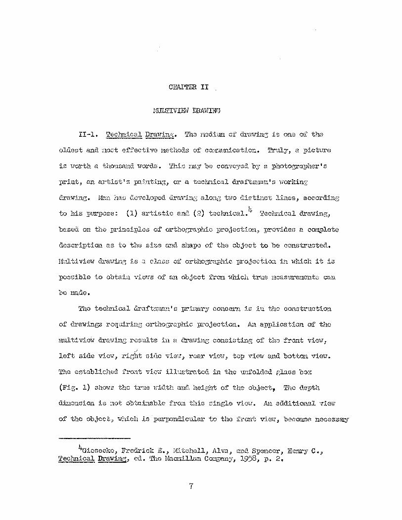
II-1. Technical Drawin:o;. The l":Looitmt cf d:rawinc: is one of the
oldest and uost effective methods o:f' 0.01-mnunication. Truly, a pictv.xa
is worth a. thousand words. This nay be convoyed. by a photographer's
:print, an artist's painting, or a technical. draftsman's working
drawing. Man has a.eveloped dr,nring along two distin.ct li.."'1.es, according
to his purpose: ( 1) artistic and ( 2) technical. 4 Technical cLT'tlwing,
based on the :principles of' orthoc;raphic projection, provides a. complete
description. as to the size an.d shape or the object to be constructed.
Multiview drawin13 is a clo.ss o:f orthographic projection in which it is
possible to obtai:n vlews of' an object frOJ'11 which true measurements can
be made.
The technical d.raf'ts:ma.n' s primary concern is in the construction
of drawings requiring orthographic projection. An application of the
mu.lti vie-tv drawing resuJ:ts in a d.rawine consisting of the front view 1
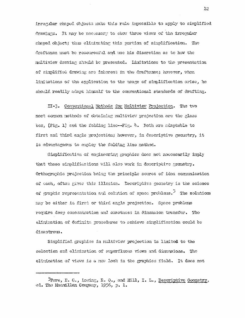
/
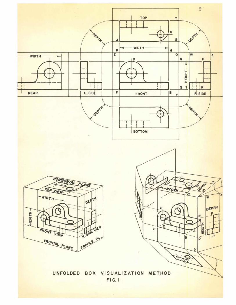
left side view, right sicle view., rear viaw, top view· and bottor:1 view.
The established front view illustrated. in the unfolded glass box
(Fig.. l) shows tho true wiclth and height of the object, The depth
din.onsion is not obtainable from this sLT1gl.e viou.. An a.a.di tional view·
of the object, which is · perpendicular to the front vimr, becomes necessmy·
4Giesecke., Fredrick E., ifdtchell., Alva., an.d Spencer, Henry c • ., Technical. DraWing, ed.. The Macmillan Cor.'.\I)any, 1958, p. 2,.
7
- -WIDTH
I I 1
REAR
TOP
I I 1
(:)~ ;,o>.
J ,s,
K WIDTH
H z
I I I I I I
L. SID F FRONT B
~~ ~ Q .+ •• -
1 I 1 I
BOTTOM
UNFOLDED BOX VISUALIZATION METHOD
Fl G. I
8
T
~~ s ~ Q
0 w X N p
Q
to obtain the depth diuension . Tlis viev , known as the top view, also
appears with the width dimension while the height appears only in the
front view.
9
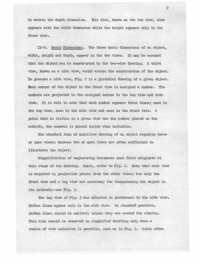
II-2 . Basic Dimensions . The three basic dimensions of an object,
Width, height and depth, appear in the two views . It may be assumed
that the object can be constructed by the two-view drawing. A thir d
view, known as a side view., would assure the construction of the object .
To procure a side view, Fig. 2 is a pictorial drawing of a given object .
Each corner of the object in the front view is assigned a nun.bar . The
numbers are projected to the assigned corner in the top view and side
view. It is well to not e that each number appears three times; once in
the top view, once in the side vie't and once in the front view. A
point that is visible in a given view has the mun.bar placed on the
outside., the numeral is placed inside when invisible .
The standard form of 11ultiview drawing of an object requires three
or more views; whereas two or 11ore views are often sufficient to
illustrate the object.
Simplification of engineering documents must first originate at
this stage of the drawing. Again, refer to Fig. 2 . Note that each view
is acquired by projection points from. the other views; but only the
front view and a top view are necessary for dir.iensioning the object in
its entirety--see Fig. 3.
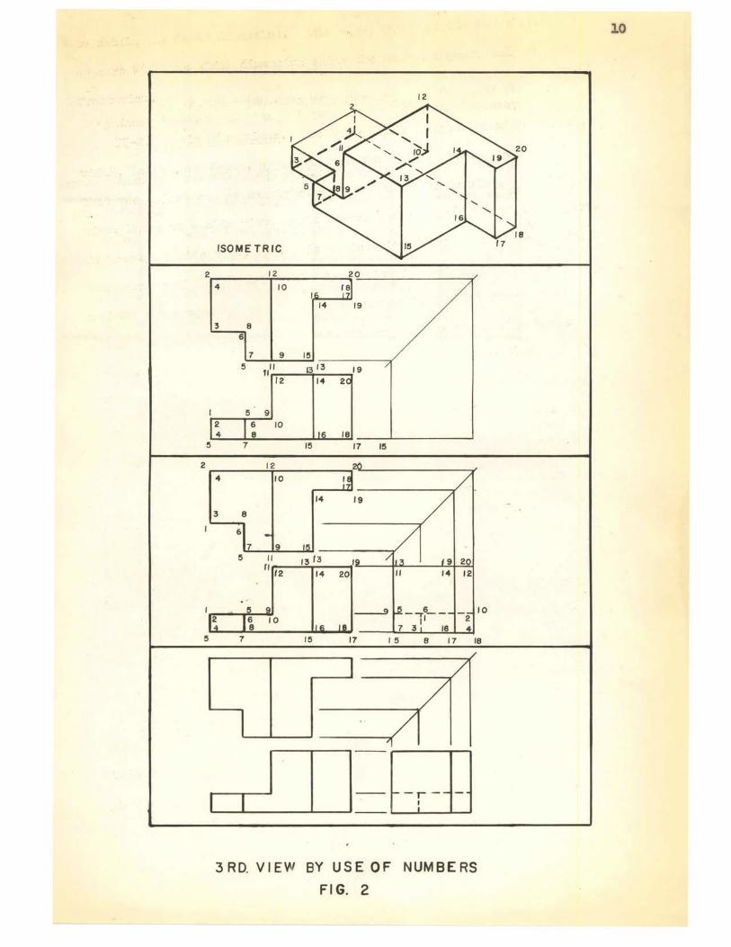
The top view of Fig. 3 was se lected in preference to the side view .
Hidden lines appear only in the side view. In standard practice,
hidden lines should be omitted; unless they are needed for clarity.
This rul.e should be observed in si.I:i.pl ified drafting only when a
choice of view selection is possible, such as in Fig. 3. Quite often
2
5
2
5
12
ISOMETRIC
12 20
4 10 re
14 19
3 8 6
7 9 15
5 fill 13 13 19 12 14 2
5 9 2 6 10 4 8 18
7 15 17 15
12
4 10
14 19
3 8
6
7 5 13 13 9 20
14 20 14 12
-,6 __ - JO ,1 2
7 3 16 7 15 17 15 8 17 18
3 RD. VIEW BY USE OF NUMBERS
FIG. 2
10
--rtl!CD r
-
-
j ~Im
u a:: 1-LtJ ~ 0 (/)
~ w >
a z w
1-~~1 t
LO,~ ~ w
L -> Q.
0 I-
-ELIMINATED VIEW
FIG. 3
a,(~
~
t "'Iv
J~,mL
11
3 UJ ->
-IN I-z
C\I 0 a:: u.
-
12
irrecular sr.i.aped objects 1,1.ake this r-1.1.le im1'.JOssible to apply to sinipli:f'ied.
shapec1 object; tllu.s 0lirtlnt1.tin~ this portion of sinlplii'ica.tion. The
{!.raftmiltln. uust bo resourcG:t'tU and use his discretion. as to how the
mu..tiview drawing shou.lc1 be presented. Linitations to the :presentation
li"ti:tations of the application to the usaee of sim:t,lif"icat:ton arise., he
should. readily aD.apt r.r!.qsolf to the conventional standards of dra:fting.
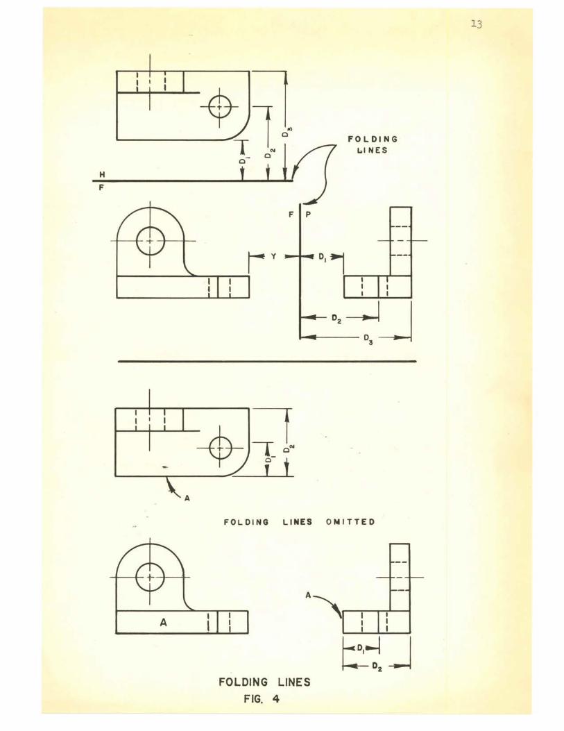
II-3. Conventional Methods~ Multiview Projection. The tvo
aost common. r1ethocls of' obtainiz1g :w.u.ltivie1:r ;projcct::i'..011 a.re the (3'lass
box, (Fig. 1) and tho i'oldLrtg J.ine--:rn,g. 4. Both are adaptable to
first and thircl angle projection; however, in descriptive ge0'.:;1.etry, it
is advan.tageoiw to enplo;y the folding line :method.
Simplification of en(Sineoring g,,1:~a:pb.ics does not necossaril;:i· iuply
that those sinrili:f:i.c:ations 1till alr;o work in doscrirJ'dve ,zeametry.
Orthoc;ra:phic projocticm bcin;; the principle source of id.ea corIO.unication
of oach., ofte:n giv0s this illv:.S:i.on. Descrirstive geonetry i.s the science
of t~aphic reproso::1t;a tior:i. aml solution of' SJ?3CO prohleu.s.? The solutiom
nay be either in. first or third. angle proj:act:i.on. Spc·1co :problmlS
x·ecp,'.ire deep concentration an~- mwotnosG ill dinension transfer. The
alinination of dc.f'i::rlt~ ::vrocedures to ochievo sinplification could. be
disastrous e
Sinplified graphics in a1u.tiview :projection is limited to the
selection exr.d clinination of superfluou.s iriows and dimonsions. The
elini:n.a:tion o:f views is a new loolc in tho graphics ±':told. It does not
5Fare, E. G • ., Loving, R. o., and Hill, I. L., Descriptive Geometr~, ed. Tho Macrlillar1. Company, 1956, :p. 1.
I I I
H
F
I I I
A
A
FOLDING L..I NES
FOLDING LINES OMITTED
FOLDING LINES
FIG. 4
13
14
ma,tter ho1 well a dra Ting is presented, if it lacks simplicity and
instruction, the purpose is defeated. Conplexity of views that are
superfluous requires time of the blueprint reader and introduces the
potential error involved in the intricate reading of the blueprint .
Simplification of multiviews can lead to a number oi' significant
iilprovements . Where it is applied, output can be increased and efficiency
improved measurably. The engineering-draftsman ratio previously stated
can possibly be reduced and the technician shortage may be relieved in
this manner.
II-4 . Drafting Objectives . The draftsman must treat an engineer~
drawing as a highly technical docur:ient and not as a work of art. Too
often the necessity of a view is not analyzed; and the draftsoa.n will
consider it sacr ilege not to show the three principle views of an
object. The beauty of the drawing receives the emphasis, and the
efficiency along with the intended purpose, meets with failure .
A drawing fully executed will possess four qualities; simplicity,
legibility, accuracy and neatness. There can be no cocipramise with this
ftm.drunental concept . It nust have enough lines to ccnvey what was in
the mind of its creator, no more, 110 less. 6 It must be legible as well
as simple, permitting the cOr!mon shop man to interpret its meaning.
Accuracy must be of the highest quality. Projection and. dimensional.
errors can be costly to industrial manufacturing concerns. The
draftsman should strive for neatness. If the drawing is to have
accuracy and legibility, it is essential that neatness be of the utmost
importance in the mind of the creator .
6iiau, A. H., "Row ti Simplify Engineering Drawing", ed. The ~ Age, December 27, 1958.
15
Emphasis on creative thinking is the major part of an engineer ' s
or drafts.r.ian's job. The drawing is a mnor part of the job. If' less
tine is spent on tho drawing, more time may be allowed for creative
thinking. Simplification and standardization of docum.ental drawing is
the answer to this "time" problen.
Simplification of forms, such as bills of material that accompany
the multivie11 working drawing, is another means of ti:r.i.e saving. They
govern the form and determne the work flow through engineering and
production. Simplification of the design of these forms through the
areas of operation definitely result in tine saving.
Standardizing sinplifications, other than elininating superfluous
views, must be considered. The existing views and dimensions are also
subjects for simplifications; however, before partial views, non-
elaborate pictorials, synbols, photography and nechauical aids are
discussed, the draftsman and ensineer should be cautioned. Over
simplification, without standardization, can break down the flow of
comt1unication and defeat the time saving purpose. Again, the question
presented in Chapter I by Rau and Healy, "What are the nininu.un data
necessary for complete understanding?117 must be asked before undertaking
the graphic simplification of an engineering document .
Proposed sil1plified drawing practices and siI:q>lified graphic
exanples will be presented in Chapter III .
1 Healy, W. L., Rau, A. H. , Simplified Drafting Practice, ed . John Wiley and Sons, 1953,
CHAPTER III
SIMPLIFIED DRAWING PRACTICES
III-1. Draftin5 Standards. Drafting roon standards are far
different fron those of yesteryear. Techniques have been revised and
drawing papers are being replaced with synthetics such as r:iylar and other
polyester films . Opaque white paper and manila. paper were the accepted
engineering document naterials; whereas today, the diazo process has
elininated this :material from. all drafting departments . All drawings
were inked in with carefully graduated lines . To further achieve an
artistic look, colored inks were used . Every bol t, nut, etc., was
drawn in complete detail . The lettering resembled that of a coDmercial
artist with fancy frills and, quite often, not too legible. Time was
of no importance and drafting costs were never considered as an important
iten to engineering.
Today, time is money and American industry is looking for all
valid cost reductions. The engineering and drafting departnents are
no exceptions to this rule, they must be restricted to the bounds of
a budget .
Competitive nanufacturing brought about cost-conscious
engineering and drafting departnents. ~hading, shadowing and coloring
is beginning to disapp~3r and. eventually most ink drawing will probably
be the exception, rather than the rule .
III-2. Acceptance of Sinplification. Industry is beginning to
16
17
feel that drafting practices should be further simplified. The
individual company procedures of simplification have produced poor
drai'ting and ill ogical theory . The damage from this type of si.nplifi
cation has been inflicted on companies that are hesitant to use simpli
fication imtil it has been accepted by the American Standards
Association or Mill tary Standards . To further examine the penalty
inflicted on the hesitant company, one must analyze their predicament .
A company under goverll!!lent contract cannot use any form of simplified
drawing . All drafting procedures must meet the requirements of the
Military Standards publications and blueprints of individual p;irts .
A bill of materials must accompany the purchase requisition . Standard
purchased parts, taken from vendors' catalogs are included in the demand.
If simplified drafting was used by the vendor, it would be necessary
for the ccmpany, which is under government contract, to redraw the part,
observing the practices of the Military Standards . This is not only a
cost burden but also one of time . The results of this would be that
they are sympathetic With the basic idea, but under government contract
would not be receptive to any pha.se of simplified drafting. The
immediate answer in overcori.ing this undesirable situation lies with the
acceptance or complete rejection of simpl ified drafting by the two
recognized standards co:mmi ttees, American Standards Association and
Military Standards Publication .
III- 3. Standard Practices 2f Simplified Drawing . A summary of
practices advocated in simplified drai'ting is as follows:
1. Word description on a drawing form should replace the drawing
wherever practicable .
2. Eliminate an unnecessary view.
3. Draw partial views wherever possible.
4. Draw half views of syx:unetrical parts.
5. Coord.ina ted preplanning of drawings.
6. Establish a standard parts cross index systeI:1.
7. Avoid elaborate pictorials and repetitive details.
8. Represent bolts, nuts, rivets and other hardware by center
lines.
9. Omit section lines wherever possible.
10. Represent holes by neans of center lines on bolt circles.
11. Use simple delineations for comnon objects. (Symbols)
12. Use free-hand drawing uhorever :practicable.
18
13. Keep letterine to a trl.nimun and avoid lettering instruments.
14. Use tine-saving devices such as templates and overlays,
wherever practicable.
15. Use photography when applicable to drafting .
16. Use cannon abbreviations and symbols .
17. Use :preprinted engineering forms and fade-out guide line
papers.
III-4. Sin;plified Drafting Applied. The application of the above
practices are simple and, quite often, the normal reaction of the
draftsman's thinking. Thread symbols-, for example, are one form of'
simplified drafting that bas been accepted by both the American
Standards Association and Military Standards. The symbol is the same
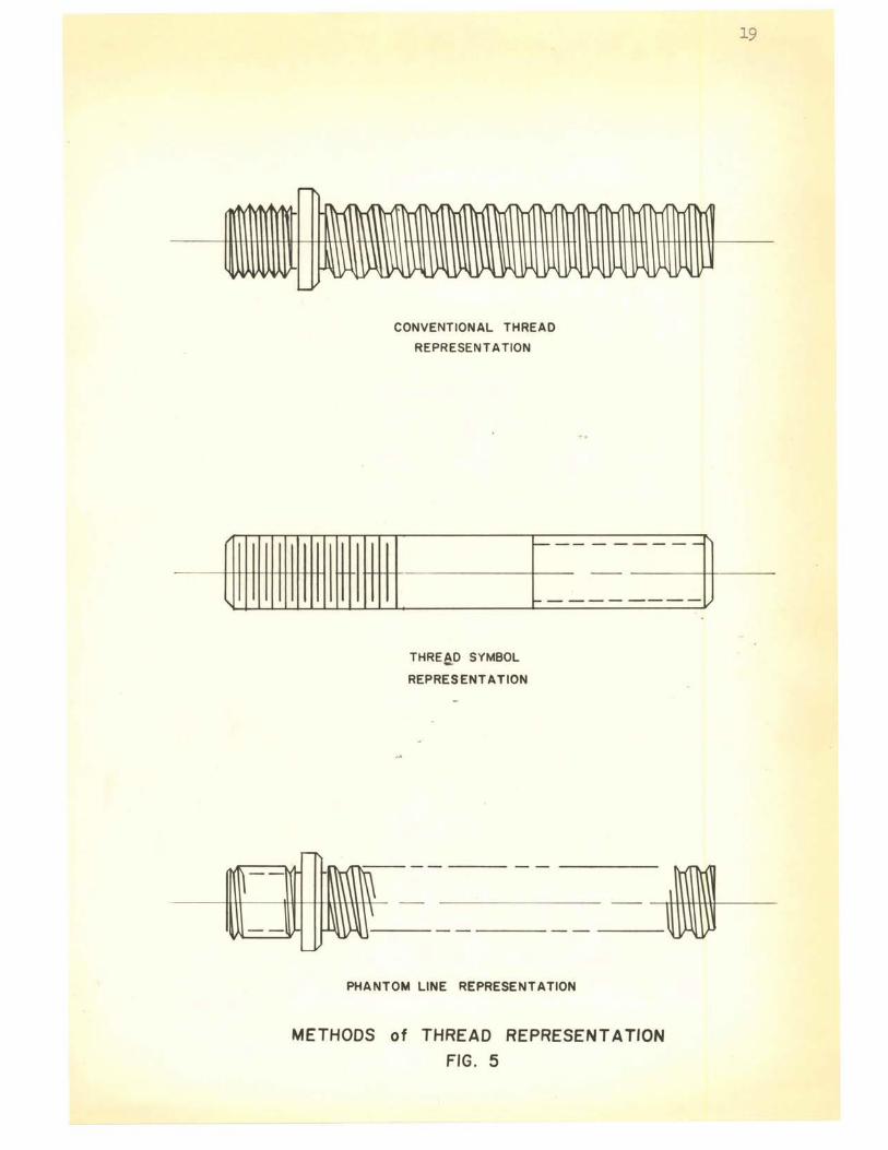
for all thread forms, such as, V, square, acme, unified, etc. Fig. 5
illustrates the use of the symbol, the phantom line, and the conventional
method of drawing threads. Time savings are greatl y increased by the
use of the thread synbols.
-~ '
..... ~
:1 nn nnFln n n i1 n n
I 1 \
~~~l § ~ ~ II..~ L '- I-
CONVENTIONAL THREAD
REPRESENTATION
~11111111111111 M++++-t--11111 -----[ -----~--]
THREaD SYMBOL
REPRESENTATION
PHANTOM LINE REPRESENTATION
METHODS of THREAD REPRESENTATION
FIG. 5
19
20
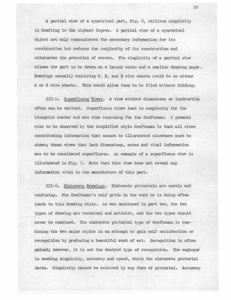
A partial view of a syrn.etrical part, Fig. 6, utilizes sinplicity
in drafting to the highest degree. A partial view of a sym.etrical
object not only Caru!tunicates the necessary information for its
construction but reduces the con~lexity of its construction and
eliminates the potential of errors . The simplicity of a partial view
allows the :part to be drawn on a larger scale and a smller drawing pa.pet'.
Drawings normally requiring C, D, and E size sheets could be on either
A or B size sheets. T'ais would allow them to be filed without folding.
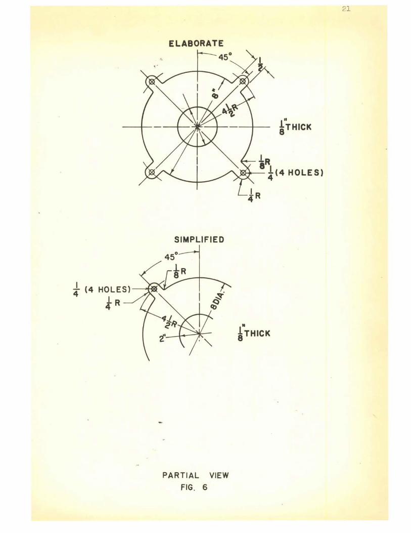
III-5. Superi'luous Views. A view without dimensions or instructicn
often can be or1itted. Superfluous views lead to complexity for the
blueprint reader and are tine consuming for the draftsman. A general
rule to be observed by the simplified style draftsman is that all views
contributing information that cannot be illustrated elsewhere must be
shown; those views that lack dimensions, notes and vital information
are to be considered superfluous. An example of a superfluous view is
illustrated in Fig. 7. Note that this view does not reveal any
information vital to the manufacture of this part.
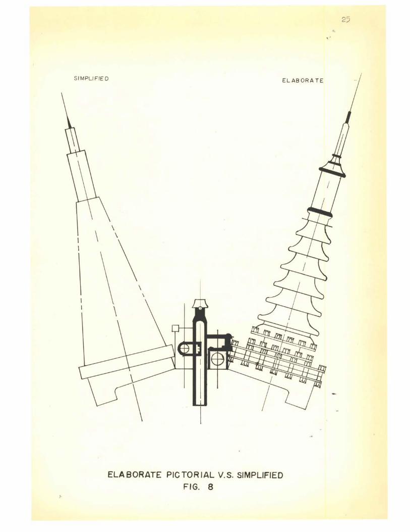
III-6. Elaborate Drawings. Elaborate pictorials are costly and
confusing. The draftsnan' s self :pride in the work he is doing often
leads to this drawing style. As was mentioned in part two, the two
types of drawing are technical and artistic, and the two types should
never be combined. The elaborate pictorial type of draf'tsnan is com
bining the two najor styles in an attempt to gain self satisfaction or
recognition by producing a beautiful work of art. Recognition is often
gained; however, it is not the desir ed type of recognition. The employer:"
is seeking simplicity, accuracy and. speed, which the elaborate pictorial
lacks. Simplicity cannot be achieved by any form of pictorial. Accuracy
J (4 HOLES)-~
!R
ELABORATE
SIMPLIFIED
45°
PARTIAL VIEW
FIG. 6
21
lR W11"-
8 !<4 HOLES)
• ~THICK
I I I I I I I
-----
i----
-
Cl) ::)
0 ::) ...J u. er u.J a. ::) en
~
------
-
-----
·,-
1· qa>
I C\J
TJ 2
j
-Iv v
f IOl<X>
t
l1
I{) l<X>
L
l-11 4
SUPERFLUOUS VIEW FIG. 7
22
21. 2
10la:>
t
_j .L ~ 2
,..,, <X)
C\J
- -( + I
\_L/' t -Iv -
I _J -
23
is quite often lost by the emplo;yment of perspective to gain the
natural shape and appearance of the object as it would be seen by one's
normal visua:Lization. Speed is sacrificed when artistic abilities are
used. Art should be restricted to the production illustration department,
and there used in a linited nanner for catalogs, part sheets and
brochures. Manufacturing and :production are not interested in
beautifully executed drawings and layouts. Their objective is to
receive a complete, concise, sinple and accurate engineering drawing on
time. Fig. 8 is an example of simplified versus elaborate pictorial.
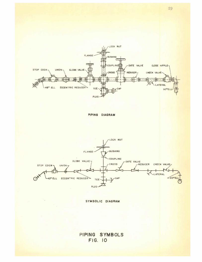
III-7. Symbolic DraWing. S;ymbology in the graphics field has
developed in an evolutionary manner. The more prominent fields employ
ing s;ymbols are the piping drafting, electrical and electronic drafting,
and architectural drafting (plum.bing, wiring and heating-air condition~
facilities); while others are still experimenting with the detail of
limitations.
The limitations concerning most manufacturers are those of
standardization. Again, may we state that symbology has developed
in an evolutionary nanner and, in so doing, has created the revisions
of many symbols. An example of s;ymbol evolution is the inductor and
capacitor, Fig. 9. Note that the inductor (a) resembles the actual
industor, as if it were a picture, (b) is the first simplification; but
still resembles the part itself, (c) and (d) are both approved standard
symbols for induction coils with emphasis being p~.aced on (o). The
capacitor has followed much the same evolution pattern With the emphasis
being placed on (e).
Symbol standardization faces difficulty today because of the
elapsed time before a forn of standardization was introduced. An
24
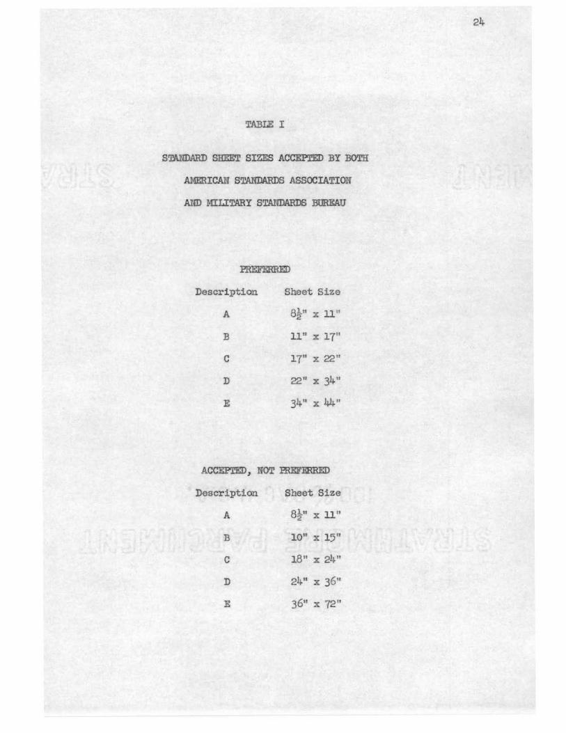
TABLE I
STANDARD SHEET SIZES ACCEPI'ED BY BOTH
AMERICAN STANDARDS ASSOCIATION
AND MILITARY STANDARDS BUREAU
PREFERRED
Description Sheet Size
A Bi" X 11"
B 11" X 17"
C lT' X 22"
D 22" X 34"
E 34 11 X 44"
ACCEPTED, NOT PREFERRED
Description Sheet Size
A stu 2 X 11"
B 10" X 15"
C 18 11 X 24"
D 2411 X 36"
E 36" X 72 11
SIMPLIFIED ELABORATE
\ \ \
ELABORATE PICTORIAL V.S. SIMPLIFIED FIG. 8
25

INDUCTORS
OLD DRAWING SIMPLIFIED DRAWING
(A) ( B)
(A)A.'H,(B) APPROVED STANDARDS FOR INDUCTOR SYMBOLS TODAY
-----1)-f -
TODAY'S STANDARD
---+---IDt,-_--
SYMBOL S04ETIMES
USED P'OR
ELECT ROL YT IC CA.PA Cl TOR
CAPAC I TORS
-1-1-OLD SYMBOL
=1--OLD SYMBOL STILL USED IN
INDUSTRIAL !:'.LE 'TRONICS
FIELD
ELECTRICAL SYMBOL EVOLUTION
FIG. 9
26
27
ex.ample, such as Fig. 9, indicates that the inductor symbol accepted
by the American Standards Association can be either {c) or (d). The
adnission of this statenent is to adrtit that standardization does not
exist with our standardizing bodies. The point made i n the above
ex.ample is a simple one; standardiurti~n, to be effective, oust be a well
thought out plan and enunciated. well in advance of industrial acceptance.
Once industry bccones the instigator, it :i.s inevitable that standardiza
tion will neet with the difficulties in establishing adopted policies.
This difficulty has occurred in synbolic electrical and electronic
drawing . Standardization by the Anerican Standards Association, ASA
y32 .2-1954, ASA YI5 .l, ASA y32.9-1943, ASA z32 .2.3-1949 and ASA Yl0.9-
1953, has served as the guiding factor for accepted procedures . The
sinplicity of synbolic piping drawing is illustrated by Fig. 10. Note
that symbol interpretation is aided by the naning of each part . This
should not be standard procedure for sinplified drafting practice and
should be eliminated f'rom. an industrial type drawing. Part names are
permissable but should not be reconmended . If a full utilization of
drafting simplifications is realized, the elimination of part names must
be onitted fron the drawing.
An additional tine saving procedure can be employed by the use of
teI:1plates. Both symbolic and conventional tenplates are available from
various nanufacturers, such as Rapidesign Incorporated. The utilization
of teuplates should be encouraged _in industrial drafting depirtments
and will be discussed further in section III-10.
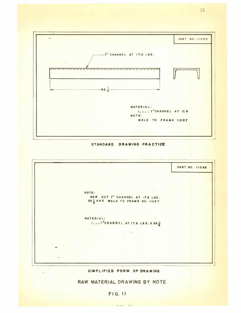
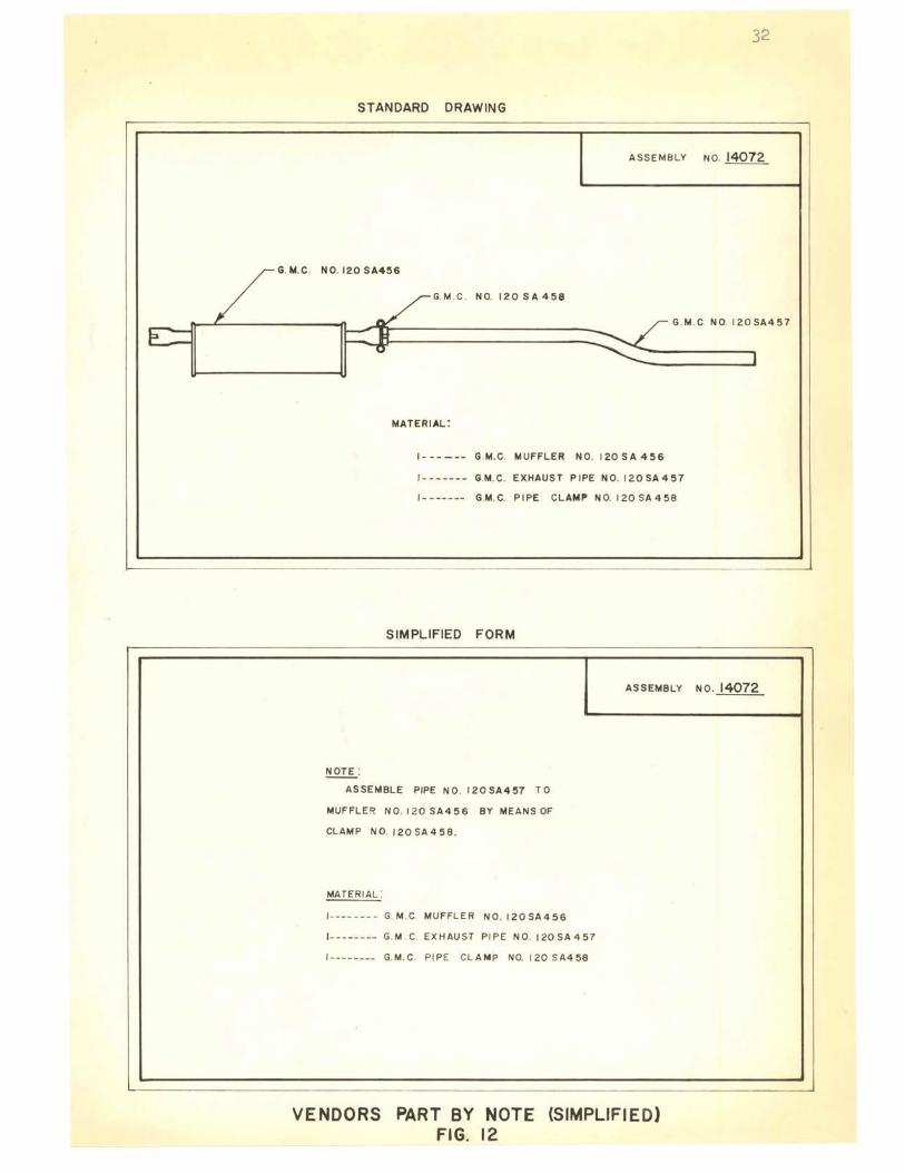
III-8. Note Descriptions. Views, and quite often a drawing in its
entirety, can be eliminated by a note. This procedure is utilizing
simplified drafting practices to the utmost extremities . Successful
28
usage of this type of simplification is dependent upon simple parts in
the raw stage and vendors ' itens . I t should never be attempted on parts
requiring drilling, wchining, welding, or other intricate shop
procedures . Full realization of this practice is limited; however, nany
drawing hours and I!l.anufacturing cost can be reduced by its practice.
The conventional multiview drawing, compared with the simplified
note method, is illustrated in Fig. 11 and 12. Each are complimented
with exact detailed communication to the blueprint reader. A bill of
materials will accoo.pany both to the nanufacturer ' s shop. The note,
however si!nilar it may be to the bill of t1aterials, should not replace
this description. In m.ost engineering and drafting depnrtnents a part,
regardless of its simple design, requires a give!l part nun.ber. Once
this number has been issued, a drawing of the part must be drawn and a
permanent document filed .
The sir.lplicity of the note system makes it desirable, but discretion
should be employed. Misuse can lead to conmunication breakdown between
shop and engineering, and create r:rany undesirable situations for
liaison personnel .
III-9. Mechanical Drafting Aids. Mechanicel aids simplify drafting.
Automation designs for other phases 0£ industry have been r eflected back
to the drafting field . The design.er has realized that autonation can be
used to help relieve the draftsman shortage. The Boeing Company has met
this challenge and has partially completed one innovation that will ease
the load of the engineer and draftsnan. This innovation has been named
a "Plotter-Verifier" which is capable of drafting from instruction
dictated by computer tapes. This nachine was constructed originally for
verifying magnetic tapes, used for nur.ierical control machining; but it
PIPING DIAGRAM
FLANGE
GLOBE
SYMBOLIC DIAGRAM
PIPING FIG.
SYMBOLS 10
VALVE REDUCER
CLOSE NIPPLE
29

30
also has the capability of making line drawings, airfoils, three-view
\ drawings of parts, charts, or any other drawing that can be defined
through the use of computed point data .8 The tape computer has a ball
point pen that responds to instruction from the tape and noves in the
quadrant directions of x, y , and z. A savings in tim.e and an increase
in accuracy are significant benefits . An added feature is that once the
taper is prepared, it can be catalogued and s tored . At any future time
the drawing can be reproduced within seven to ten minutes .
Other more connon nechanical aids incl ude drafting machines,
mechanical pencils, electric erasers, electric calculating o.achines,
electric drafting typewriters, plastic cutout templates, cellulose
acetate appliques, self-adhering layout tapes, etc . The echanical aids
are probably the nost recognized tine savers ; however, a very important
complimentary feature is the reduction of the mental and physical efforts
of the draftsman .
III-10. TerJ.Plates . A large selection of templates are available
for specialized needs. A template may be found for drawing any symbol
that has been approved by either American Standards Association or
Military Standards. The tenplates receiving the nost popularity are
the circle and ellipse; however, there are others that justly deserve
their place on a drafting board .
Util izing the tine saving templates is the r esponsibility of al l
simplified type draftsmen . The template is accurate and, in most
cases, to a closer tolerance than can be drawn by the draftsman.
Srielson, L8onard A. , "Training For Change in Drafting and Design," ed. Reproduction Engineer, July, 1961, p . 250 .
~
'
-
r L
31
I PAR T NO. 11056
;- 7" CHANNEL . AT I 7. 6 LBS .
I
I - -I/ ~ I
I 36 4
MATERIAL :
1--- - 7"CHANNEL AT 17. 8
NOTE :
WELD TO FRAME I 10 ll 7
_ _j
STANDARD DRAWING PRACTlot
I
I PART NO. 110158
NOTE,
SAW CUT 7 11 CHANNEL AT 17.6 LBS. 36iAND WELD TO FRAME NO . 110~7
MATERIAL•
1 ___ 7"cHAHNE L AT 17. 6 LBS . X38t
SIMPLIFIED FORM Of' DR-AWING
RAW MATERIAL DRAWING BY NOTE
Fl G . . 11
I
- ~
32
STANDARD DRAWING
ASSEMBLY NO. 14072
G. M. C. NO. 120 SA456
G. M. C . N 0. I 2 0 SA 4 5 8
G. M. C. NO. 120SA457
MATERIAL'.
1------ G.M.C . MUFFLER NO. 120SA456
1------- G.M. C. EXHAUST PIPE N0. 120SA457
1------- G.M. C. PIPE CLAMP NO. 120 SA458
SIMPLIFIED FORM
~ : ASSEMBLE PIPE NO . 120SA457 TO
MUFFLER N 0. 120 SA4 5 6 BY MEANS OF
CLAMP NO. 120SA458.
MATERIAL:
1- --- - --- G. M.C. MUFFLER NO. 120SA456
1- ------- G.M . C. EXHAUST PIPE NO. 120SA457
1-------- G.M.C. PIPE CLAMP NO. 120 SA458
ASSEMBLY NO. 14072
VENDORS PART BY NOTE (SIMPLIFIED) FIG. 12
33
The shapes of some tenplates are so designed that they replace the
45c triangle, 30°-60° triangle, and French curve; thus, eliminating
the expense of purchasing two devices, plus, decreasing the number of
instruoents required on the drawing board while working. The templates
are generally made of .030 inch matte finish mathematical quality
plastic, giving them a durable finish.
An additional feature of interest to the simplified type draftsman
is the specially designed template which 1Dlly be ordered in quantity, per
custo er ' s specification. This can prove to be beneficial for use on
co pany insignias, title blocks and special notes that are placed on
each drawing. The aid of a tenplate allows the draftsnan to trace
rather than draw this special material. Cost of the special template
may often be prohibitive ; however, a cost analysis of the job often
reveals that the special template will warrant the high cost involved.
An extensive selection of' templates to aid engineers and
draftsmen are available by r:ianufacturers, such as Rapidesign, Post,
Handy, Roark, Dietzgen, Timely, Keuffel and Esser, and Wrico.
Lettering templates are also avail able but are not recommended for
use by the simplified draftsman. Contrary to other templates, they are
more time consuming than the free-hand style of lettering. With the
emphasis being placed on drawing time, the simplified type draftsman
should practice a legible, neat, modified gothic style of free-hand
lettering. The aid of an Ames Lettering Guide, or equivalent, should
be employed. With this instrument, unifol'I!lly spaced sets of guide lines
are accurately and easily constructed. The choice of different ratios
for the spacing within each set of guide lines is provided. These ratics
allow various sizes of inclined or vertical type of letters to be nade .
Lettering devices, other than Ames, may be :purchased. They are the
Braddock and Wrico. Es ch is incorporated into a 45° triangle, which makes
it universal for other uses.
The sin.plified draftsman should keep well informed on new template
products being placed on the market . He should diligently employ
templates wherever possible and be familiar with the various time
snving qualities of each template . The template may be regarded as one
of the most in.portant instruments used by the sir.lplified style draftsman.
III-11. Complexity. Complex parts can be described more readily
and economically with a drawing than by conversation. The purpose of an
engineering drawing that demands an engineer or draftsman's explanation to
accomp:tny the drawing is defeated before it leaves the drawing board.
Costly revisions are generally inevitable and will be necessary before
the part can be manufactured economically.
Complexity can be obtained within a drawing by such simple things as
line weights, arrows, notes, circles, etc . To avoid this type of com
plexity, the draftsman must adopt certain simplified practices. Some
of the najor practices have been discussed in the preceeding :paragraphs.
It should be accepted that the large tine savings are achieved by the
major practices; however, there is much to be said in behalf of the
small minute practices.
Architectural draftsnen have been credited as the first to eliminate
the arrowhead. This small but quite significant symbol, indicating the
extent of a di:nension or leader, has long been a proble:o for the
beginning draftsnan. Its size and shape has varied from one draftsnan
to another. Anerican Standards Association recommends that a uniform
size and style be naintained. The l ength of' one-eighth inch should be
average and the width appro:xil!lately one-third of the length. They shoul d
be tmiform in size and style throughout the drawing; regardless of the
size of drawing or the length of the dimension.
Arrowheads should be omitted except where necessary for clarity.
35
When arrowheads are drawn by the dozens in ter:cts of the "time" needed to
draw each, they add up to a sizeable amotmt of drafting tine . To
simplify and initiate a oore controllable means of indicating the extent
of a dinension or leader, the architect has introduced the point method.
Much can be said in favor of the simplicity and uniformity of the point
method. These favorable facts are: experience is not a necessity for
the construction; a sharp pencil lead is not necessary; simple one-strolB
construction; prints well; envolves no side arm movenents; and is clear,
distinct and tmiform. See Fig. 13. The conventional arrowhead can
offer no advantages over the point nethod.s, and is indeed a "time
consumer" conpared with the point.
Another conplexity is the circle placed around the material
identification nll!!lber and revision letters. The significance of the
circle is to allow the number to stand out and set it off fron the
other features on the drawing. See Fig. 13. However valid this may
seen, no proof can be given for this reasoning. An experienced blue
print reader will first read his print, next the bill of materials and
then revision block. At this point he will correlate the three and
will be faniliar enough with the drawing to isolate most material
numbers that ere of significant value. The circle, to the blueprint
reader, has served no value other than indicating completeness. This
type of completenf-lss is not desired or necessary in simplified drawing.
The final comploxi ty to be discussed is li~1e weights. This is
important to both the technical and sinplified style drafts . en. Althougi
line weights are a problem in inking as well as in pencil, the latter

23
22 21
25 26
30_/
27
ARROWS AND CIRCLES LEAD
TO COMPLEXITY
FIG. 13
37
will be of the oost inportance to the sinplified draftsman. We nornally
think of ink drawings being in other forns than simplified. This should
not imply that inld!'...c; of simplified drawings is not perm ssable . It
should be understood that simplified drawing is enployed as a "tine
saver" and i nking drawings is a "time consUI:ter"; therefore, it is not
likely that the corn ny desiring to speed up their drafting department,
would slow theI:1 down by using inks.
P ncil lines should be sharp and uniforn the enti re length of the
line. The distinction between object lines, hid.den lines, center lines
and guide lines should be pronounced. The simplified draftsman will
use this oediun to boldly present the outline of the objecv being
drawn. This will capture the blueprint reader's eye and inmediately
concentrate his attention on the construction procedures of the part.
This line should be o:r medium width and very black.
Of secondary eapbasis is the hi dden line. This is the part of the
object which is hidden fran the selected view presentation. It is a
dashed line and is classed with that of the auxiliary lines. The
darkness and width of the line is slightly less than that of the object
line.
Center lines should be used to indicate axes of synetrical objects,
bolt circles, and po.ths of motion .
In simplified dra:fting, the center line is used nore extensively
than in conventional drafting. As was illustrated in Fig. 6, the center
line shows syr.nuetry of the partial and in Fig . 8, the center lines re
present the basic outline of the elaborate part . To illustrate the
center line, a long dash; which may vary in length :f'rom. three-fourths
inch to one and one half inches, is followed by a short, one-eighth
dash line, with a one-sixteenth inch space between them. The line
should be thin enough to co trast well with the existing lines; but
dark enoug.11 to reproduce well .
Guid linas, co struction lines, or prelillina y lines should be
drawn dark enough for the draftsman to see, but lig~1t enough that they
becone invisible at e.n arm's length. In sin.plified drawing,. these
l ines should ~ever be erased w:ereas in conventional drafting, they are
often erased.
When drawing e line, the pencil should be incli ea at about 6o0 in the
direction tho li.."l.c is being drawn. Rotate the pencil very slowly
between the thumb and index finger . Never push the pencil; but it
should be pulled at the sal!le inclinatio;.1 for the full length of the
line. This will mai:::1tain a straight u..'liforLl line and uill aid in
preserving a conical point on the pencil. Sharpening the pencil often
will improve line weig..11.ts and control uniformity .
III-12. Dimensioning. Af'ter the shape of the object has been
illustrated by orthographic or pictorial views, it becomes necessary
to place dimensions on the drawing that describe the size of the
object.
The dimensions placed on the drawing are those required for
producing the object represented. Bef'ore dimensioning the drawing,
the draftsman should study the part f'rom the machinist or pattern
makers viewpoint . A nental picture should be formed and the dimensions
. arranged to best give the in:formatJ.on in the simplified form .
are:
The factors to be considered in simpl ified dimensioning practices
l. Dimensioning Technique . The first requisite is a thorough
knowledge of the function of the object and the procedure for
39
producing the part . A system.zed pattern of SJ?0cing dimensions,
"the na.king of arrowheads, and the placing of notes, becomes an
integral 1)8.rt of t_ e d.rnftmnan ' s visual p.:ct:urc .
2 . Placc1 en of Dimensions. A Tactical sL1pl e arrongenent ilith
raaxi l.lGl egibili ty should be ac_1ieved. T'1e :plac-..nent should
be a logical nd prnctlcal itc.:i from the blue rint reader's
vicupoint.. The three basic d.iuensions introduced in Part 6,
height, wid nd depth, s. ould be pl aced in the sane
arrange ent on ach object of each drawing . This sinplificati<ll
allo s the blueprint reac.er to readily pick out the three major
di ensions by scanniIG t e draw.:. g .
j. Standard Dillensioning Fcuturee. The utilization of dinensionil'.l!
standard:;, such as, Ililitar;; Standard lA, SA, and 8B,9 and
.American Staudards Asaoci tion Ylli- .5-1957 should be er:iployed. 10
4. Choice of Dinensions . The first choice of din1ensions is
deternined by the function of the :part; secondly it is deter-
mined by the I!lanufacturing process; and the final consideration
is placed on the review of the existing dinensioning to see if
improve ents can be made from the standpoint of shop procedures.
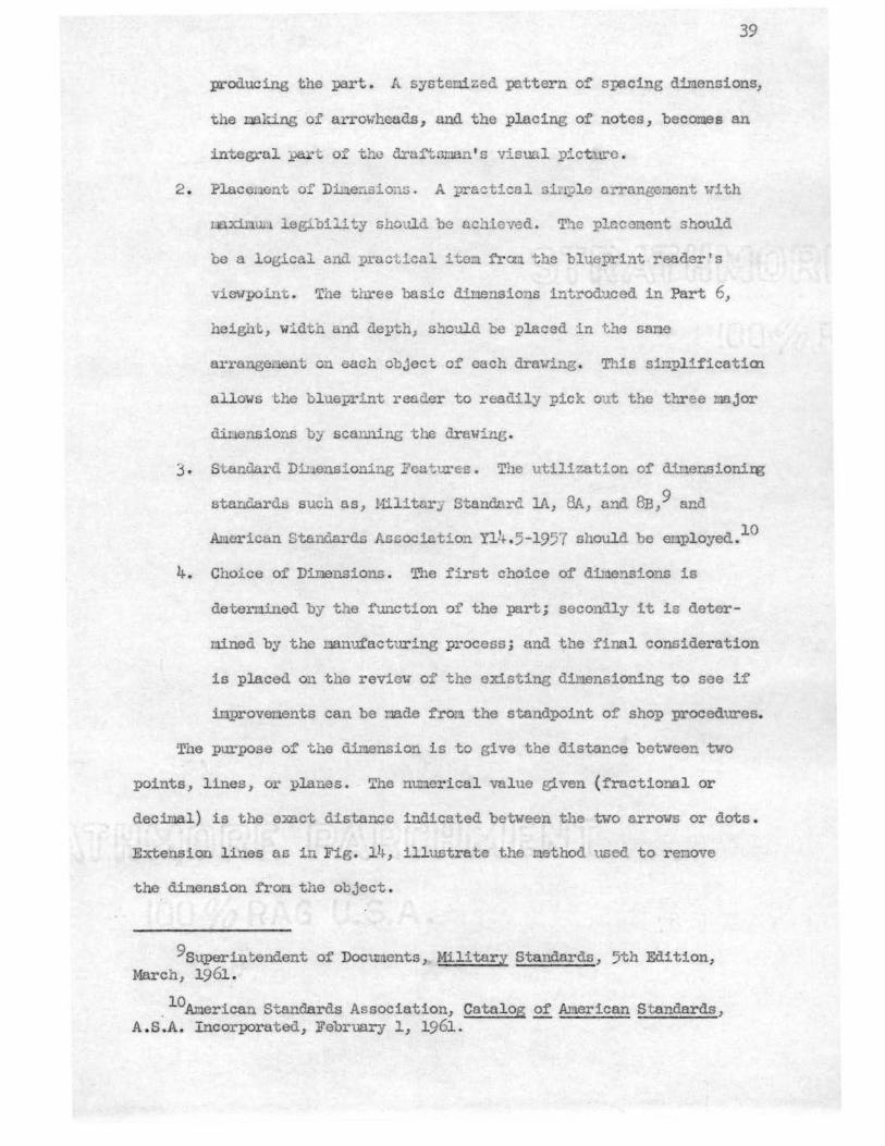
The purpo e oft e dimension is to give the distance between two
points, l ines, or planes. The numerical v l ue given (fractional or
decimal) is the e:mct distance indicated between the two arrows or dots .
Extension lines as in Fig. 14, i l ustrate the method used to remove
the dimension fro the object.
9superin tendent of Documents, Military Standards, 5th Edition, March, 1961.
. 10American Standards Association, Catalog of American Standards, A. S.A. Incorporated, February 1, 1961.
Dimension reuoval allows t e blurprint r ader a m.o:re legible
reading of the drawing and permits the object lines to stand out.
Di. ensiou line ·, e1:te_ sion lines, and leade 'S are clravn with the
su e line weight. A uediUll ha cl pencil, such as, a 4 to 6H should be
40
used and a sharp lead ould be 1.'.laintuined . A fine full line the same
wiut· of ceu ·er :in will be the result, and a sharp contrast will
exist betwe n these lL es and the object l ines .
Over sili1plificatio.a of di ensioning practice can become hazardous .
Sinplified diuensioning uust no be thought of as tho deletion of
dinensions, but rather a concise , systematic neans of dimension placing.
The unifor.u1ity of basic ditlension placing between one drawing and
another is this i'oru of simplifi ntion.
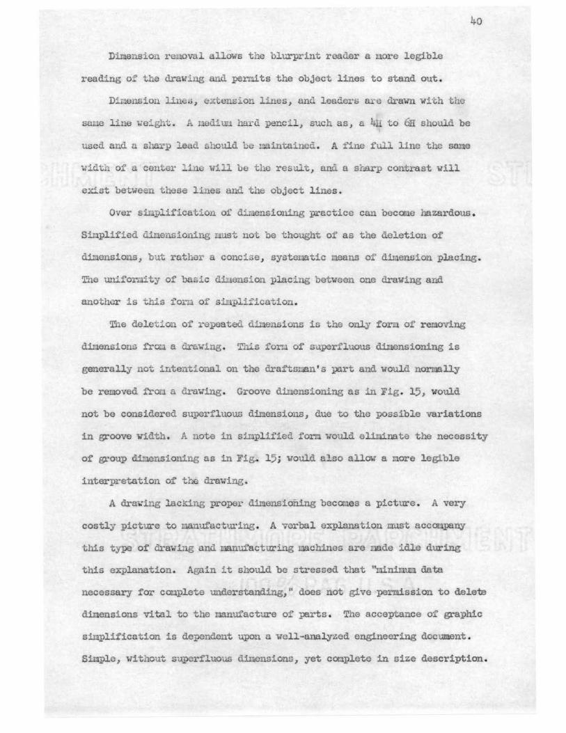
T"ne deletion of repeated dinensions is the only for~ of removing
dinensions fro:::i a dra:wing . This forn of superfluous d.il.lensioning is
generally not intentional on the dxaftsman's po.rt and would normally
be removed fror.i a drawing. Groove dinensioning as in Fig. 15, would
not be considered superfluous dimensions, due to the possible variations
in groove width. A note in sinplii'ied fern would olir.rl.nate the necessity
of group dinensioning as in FigJ 15; would also allow a more legible
interpretation of the drawing.
A dxa-wing l.acldng proper dimensioning becomes a pictm-e. A very
costly picture to Llanufacturing. A verbal explanation ml.1st acconpa:ny
this type of ch·awing and manufacturing machines are nade idle during
this explanation. Again it should be stressed that "mnim.um data
necessary for conplete understanding," does not give permission to delete
diI:J.ensions vl tal to the oonufacture of µ:irts . The acceptance of graphic
simplif'ication is dependent upon a well-analyzed engineering document .
Simple, without superfluous dinonsions, yet complete in size description.
41 -
l t
I I
I I _ j
I I I -
I
EXTENSION LINES
1 _,
I
It'l l CX)
i I I l_ • I • .]_ L _ :-----.l· =:J
DIM ENSI ON LI N E S
DIMENSION EXTENSIONS
Fl G. 14
I --- ~ -
~~ DIM F NSI ONS
I I I
L I X .l 8 8
DIMENSION BY NOTE
GROOVE DIMENSIONING
Fl G. 15
CHAPI'ER IV
PHOTODRAWnm AS A FORM OF SIMPLIFICATION
IV-1. Photodra.wing. Photodrawing, as a simplified drawing
procedure, is the nethod of making and using photographs to convey
dillension, identification, position and spatial-relationship information
i n the same manner as engineering drawings. It is very sinilar to
conventional drawing. The only difference is that the draf tsman has
made a photograph of the subject matter rather than a pencil drawing.
The photodrawing method of simplification is dependent upon the
object being built before being dravn . Usually this is not the case;
but in certain aspects of r esearch and develoP!!lent this situation does
exist . However, nanufacturing revisions of a part are often completed
before the original drawing is revised. This is an ideal situation for
photodrawing. The term. 11 simplified drawing11 applies to any subject to
be dravn, whether it be a simple tool or a complex ma.chine. When the
subject exists before the final drawing is made, a natural situation for
photodrawing exists. Countless hours of costly drafting time may be
saved through simplification methods . Furtherm.ore, the use of photodraw
ing has resulted in two oajor achievenents . These are unfailing
photographic accuracy and infinite subject detail.
The process is quite inexpensive, relative to drafting time . More
pictures can be used-,.to show prospective and concealed detail, whereas
with drawing, the number would be restricted due to the costly drafting
42
time involved •11
The advantages of photodrawings are numerous; but the most
significant advantage is that they promote quick understanding and correct
action by the ultimate user. Other uses are of equal value, but
restricted to a specific job. They are: high speed photography used to
record mechanical motions which are happening too fast for the human
eye to observe; black and white and also color photographs can be used 1P
record for analysis, the stress patterns formed when a plastic replica
of a part is subjected to undue stress .
When making the photographs for a photodrawing, it would be well
if an experienced draftsnan were the photographer . However, in the
absence of such a draftsnan, a draftsnan may serve as a consultant to
an experienced photographer and assist him in achieving the desired
angle for the photodrawing.12
The procedure for making a photodrawing is as follows: the
draftsman would first take a few basic measurements and then take as
many photograph,s as is deemed necessary. Usually an elevation, plan,
and an isometric photograph will suffice for most subjects. With the
photographs and basic dimensions, the draftsman can now prepare an
accurate drawing of the subject, should the occasion arise . This would
be done only if the object photographed was placed on a production basis.
Equip!lent edifications are quite often nade in the field. It is
not feasible for the draftsman to take the master document and make the
changes or additions under field conditions . A hand sketch of the
llKupler, Dale, 11Photodrawing", The Kodak Bulletin, May, 1961.
l2Eastm.an Kodak ComJ)8Ily, ''What' s a Photodrawing", ed. The Kodak COinJ;8SS, 2:1-12, 1961.
44
modification is generally employed. This is returned to the drawing
board and the changes are na.de on the master document. This is not only
time consuming, but leaves an opportunity for errors and the possibility
of vital dimensions being ov rlooked.
A photodrawing is extremely valuable from the standpoint of acctll'acy
and detail. Overlooked dimensions can be readily scaled and a rettll'n to
the field is elirtl.nated.
When first preparing photographs for use in photodrauings, a
photographic supplier should be consulted. Continuous revisions in the
field of photography are taking place each day, and the process and
procedure used today will change tonorrow.
Maxinum quality is essential. The photographs used for photodrewing
require considerable magnification, therefore, the utnost in shar:pness,
detail, and contrast ust be achieved.
The use of long focal length lenses helps to reduce the distortion
of converging and diverging lines. This effect is usually apparent in
a box camera snap shot taken in a small room. Vertical lines become
distorted and a"f>pear to lean outward. This must be eliminated before
scaling of the photod.rawing is achieved.
Continuous tone proof prints should be nade f'ron all of the
negatives in order to ascertain which photographs contain the desired
views and necessary detail. It is usually quite difficult to make these
decisions by looking at the image in the grotmd glass of the camera .
T king extra pictures gives assurance thet the whole story is on record.
Making proof prints is good economy, as all of the photographs
nade will not always be required. Proof prints will help nake the
decision as to what is necessary for photod.rawing, and which are of no
value other than a photograph.
The negatives should be cropped to the des ired size and a final
screen positive made on a matte polyester film . The size change involved ,
when converting the continuous tone negative to halftone positives, uill
necessitate the use of an enlarger or a process canera . Due to large
magnifications involved in naking nest photodrawings, a pmrerful l ight
source in the ca!!lera, or enlarger, will be helpful in overcoming long
exposure times .
The process as stated above , complete ; an enlarged screen positive
inage of the nodel on a natte polyester film gives a desirable positive
tte surface for the draft.sr:ian to work on. The addition of pencil
lines can be nade or the deletion of existing lines can be achieved by
eraser or cutting blade . The screened inaee is desirable, in that it
produces a far superior quality on diazo and blueprint paper than does
a continuous tone image .
IV-2 . Microfilm. Microfilming was :first conceived for the purpose
of miniaturazation and space conservation. However, there are additional
advantages to microfilm that apply to engineering simplification
procedures. They do not necessaril y appl y to drawing simplifications,
but do apply when drawings are old and worn and normally would need to
be redrawn before being restored to active use . The Ilicrofilm aperture
can be enlarged to normal drawing size, a positive matte polyester film
made, and a workabl e tlrawing achieved . Intermediate cost can be cut
considerabl y by this restoring process .
The photodrawing as a form of simplification and the dependency of
prerequisites before satisfactorily fulfilling graphic simplifications
was presented in Chapter r.v.
CHAP..!.'ER V
SUMMARY, CONCWSIONS, AND RECOMMENDATIONS
The purpose of this study was to collect data pertaining to
engineering graphics sinplification and the application and acceptance
of these simplifications by indust:i]Jpresent and give proof that
o·nplified drawing is a functional working drawing with purpose in each
and every line, legend, note and view placed on the drawina; and to
give justification for the elir.iination of superfluous views, elaborate
pictorials, hidden lines, and repetitive detail-:} .--Graphics sinplified, as this problem has presented, is an analytic
approach to the standard procedures based on sound engineering graphics ,
to relieve the t~e stress placed on to ay's engineer and drafts:i:ian.
~ata for the study were obtained by visiting various types of
industr;-/ , and a survey th.at was nailed to engineers and dra:'tsnen who
work directly with ·he problem presented • . r V -1. Problen Su:rinarized. Q. study was made on simplified engineering
graphics and the application to industry within a 250-mil~ radius of
Miami, Oklahoma':) The probleI!l was found to be quite ccmplex and it is
not in.plied that f£hapter III is t~ graphic standards to be accepted
by industry, AI.1erican Standards Association or the Military Standards
Bureau. The survey taken does indicate that fomdation does exist for
graphic simplification and the need is evident.
Ghe approach made by this study was based on sound engineering
graphics taken from recognized authorities in the field of study, and
46
47
by standards now recognized by the American Standards Association and
Mil itary Standards Bureau.
V- 2 . Conclusions . The f'ollow'ing conclusions were nade froo. this
study based on the results obtained.:
l. The average engineer to draftsman ratio is three to one .
~ . Engineering Standar d Manual s are being used in most engineering
documents .
• Engineering Standar d Manuals are made current as the revision
is being initiated.
4. I ndustr y Looks to the American Standards Association and the
Military Standards Btn"eau for the rules of standardization of
engineering graphics .
\ . Industry is lax in providing their personnel 'With standard
nanuals of company graphic policy.
6. Accuracy of engineering drawing is sacrificed to speed up
certain jobs having deadlines .
"( . Industry has no place for the draftsman with fancy frills added
to his drawing .
The draftsmn' s work is creative.
9 . Simplification standards are needed{;_nd wanted by the draftsman
and engine~ _
10. Industry is not using sinple deleneations for common objects .
n. The utilizing of drawing templates is applrent to the draftsman .
This is verified by the draftsman ' s f'Urnishing his own templates .
12. Inked drawings ar e almost obsolete, vi th the exception of
mapping and production illustration.
13 . Engineering departments are utilizing pre-printed forms .

' l
Each Draftsman Has Personal Copy
' '
Iii ixx 1
1: . ) l
~- ,> •• J -+ -; -.. _1 ___ . --·- kxxx' xxzxx Follows Military l xx;xxx, xxxxx Standards l .xxxxx; xx:oa . ·-·-· ---· ·----· ·---~ .. :a:xxxl
r ,
' ~~~!OOCCl:XX~~!£X::CO~~~ Mad.o Current~ Per Revision~ ~~.JOr.L~.
Revised Sem.i-Year.ly
:Revised Monthly
I \ ~ ! ; . 1. ; 1 I i !
!x:ioc·· ··--·+--··r ··-·· t··-- · + ····- ·----r-xxxxxxxx lxxx Sta..11.dards Manual xxxxxzxx ;x For Engineering De:partnent :x:.ioooax; '~--.----- .......... ___ ·-------------..... _ _. _________ .xx;xm
I . I -1--............. ,, ..•.. •.-•..• .,.
t!i
~ ;xx; !xx;
' : ! • •J i '.f :,-..... ..,...,..
I 8 ca
~ H ~ H H t5 ~ H
~
~ .fj
~ tQ
C)
I ~
~~Jci: ···,. ---····--·,···J ""°' .j.XXX1crl ~ Realize A Need For Graphic' xn.s--oocx..'lOOCK: Simplification Standards XXX:lCPO~::!OPPL.. • ·- .. , . --i X:,SS~
i i~i : ' ' A:re Now Using Simple I x )
Deleneations for CorJm.on Objects }Dtt ·; ,.,,,.., ___ i
~i
Are Viol~ting Simpli:ficatia."1. ' Methoa.s x
Lr . :.,,':,.
.l
. L__ i ·-·+··· .J ·---~; \y,.xxxxJ::x:coorxxxx Simplificationx ixx! k.xx1oacr:::a:~ Are Neede . x..~: iXZ,Y.,.X."{~--!'O'"..;;;,?,JQ.qqt.. .. .. ! ---- ... ·-·-.,- ~ ........ J .}'-XX:
XX:~r7--~XY~~,--· ,_ ·0s1·-v,·-=-J-~- ---,~~-.~, ! -----~~--~- - .t.X!~J ! :kX:O~~O.O-:..JDO: ~
:1:xx;;x.:ia.:::r.xx:xxxxx Work is Creative i x, kxxxxx.."QOl'.1:~oax I x:< ~{:XXX.~~sg _____ ----- _;_ --~L~=?f:
1:reed For Fancy Frills Jt
. t ... brxx:l~~ccc...~x i t • • •
/x:ior.xxxxxxxxx Surrender Accu:tacy • •· iX:lC{..'QtX~,.XX Fo:r: S:pe. ed •• ~ I . *-~tx....xr~-~~ .. ~-~, .. --~-·,~--.~~--~-~·-=----.-.. • •.,
15 s -·"' 15- "\f:' ... 0 ,-._._},
\0 tr\ ,.:j· (Y) (\J
~ ,.a 'M {/l
!l.l tQ
~ 0 f:l.-1
:;~ .:. xx ...
z 0 H
E: 0 H H p;:j 0
E-1 <l!
tr] P=i f:r:J A ~ [-i ~
<"''---l
'> _c~1 ([) r-i 9 H
·-- ·~:;1 ri E ... ~ .. :._.,, ,_ ~ ~ !'.Cl f}; 4~
E-i ,...,., 0 A 8
t.? I] ;~;"; H ~
i ;-..::..1 H e:i
~ lfzj l=t C!J -~ µ:i
--::~ 6-0 rl
E,.'lg.i..neer to Draftsman Hatio Does Not Apply
E:ngince1~ to Draftsiirtn Ratio Less 'i'han l to 3
Ri1[.;°i:t1f;a1t ..{Go- ni~:1ftsrr1Dn Ratio Gr,~ator l to 3
.,__,:--.
6' 0\
Engineer to Dra:ftGl'.11..'Ul B.a.t:i.o of l to 3
;!} 'is- ;:::;.t, ...... ~-::,, .... ~:'1< '..;.;- 8' 8 0
CD t- tC\ -=,"
-'~ 6~ (Y)
"t1':::'J... "'"'-'"'' 'l.:·i""'-o
0 0 (\J r-!
~
I ~ ~
I> ;! H
i m fj Ei ~
A ~
i ~
Coqpany Fut~shes ~la~s
i
cam.rxmy Furnisoos. Drav.tng Instrwionts
: i l
All l)raVings ' I
Inked ,
51
~ ~
1 I
I I
XlOOC
= I xx.a-
. JqX Use Tetiple.te ' x= Lettering I xh:
' x:xr-·
xxx:xx.icotxX •• • • Util i.zation of X:2X 8 &U ux • . • •
Weru,la tes . ~:lOClQCC!o: r- T. ·· T --,
I . '
i --- -- I I
~!- __ 1_.
t} t ~ M
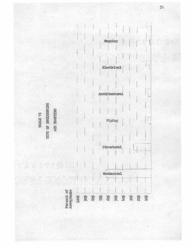
Mapping
, Electrical I i I ' ' I
Architectural I . I I
j
Piping
i !
i 1 St.ructm-ol 1
I 1
I I f f
I! j
____ J I , I
i I
' l _ .. __
52
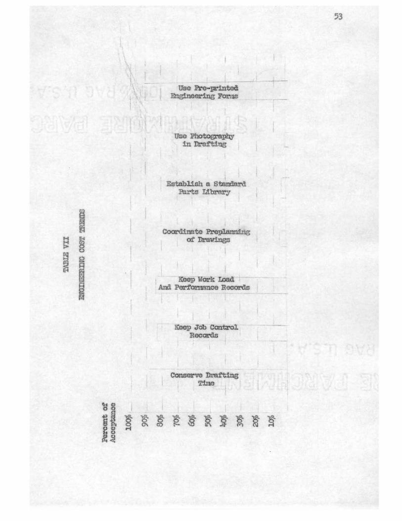
1 I
rs g
al ~ ~ 0\ oc .-, kO 8! :i
Use Pre-pri.ntocl Engineering For;. ~
Uoe Photography in Draft~
l
Establish a Standard ? ...... '"ts Library
Coordimto PreJ.>l,ann:L'tg of Drav:i.ngn
1 . Koep.Work 'U>a.d And Perf'or:mnce Records
-g. co
Keep Job Control Records
Conserve Drafting Tine
~ ~ } ~ t'-- i."\ (Y')
53
~ ~ (\J rt
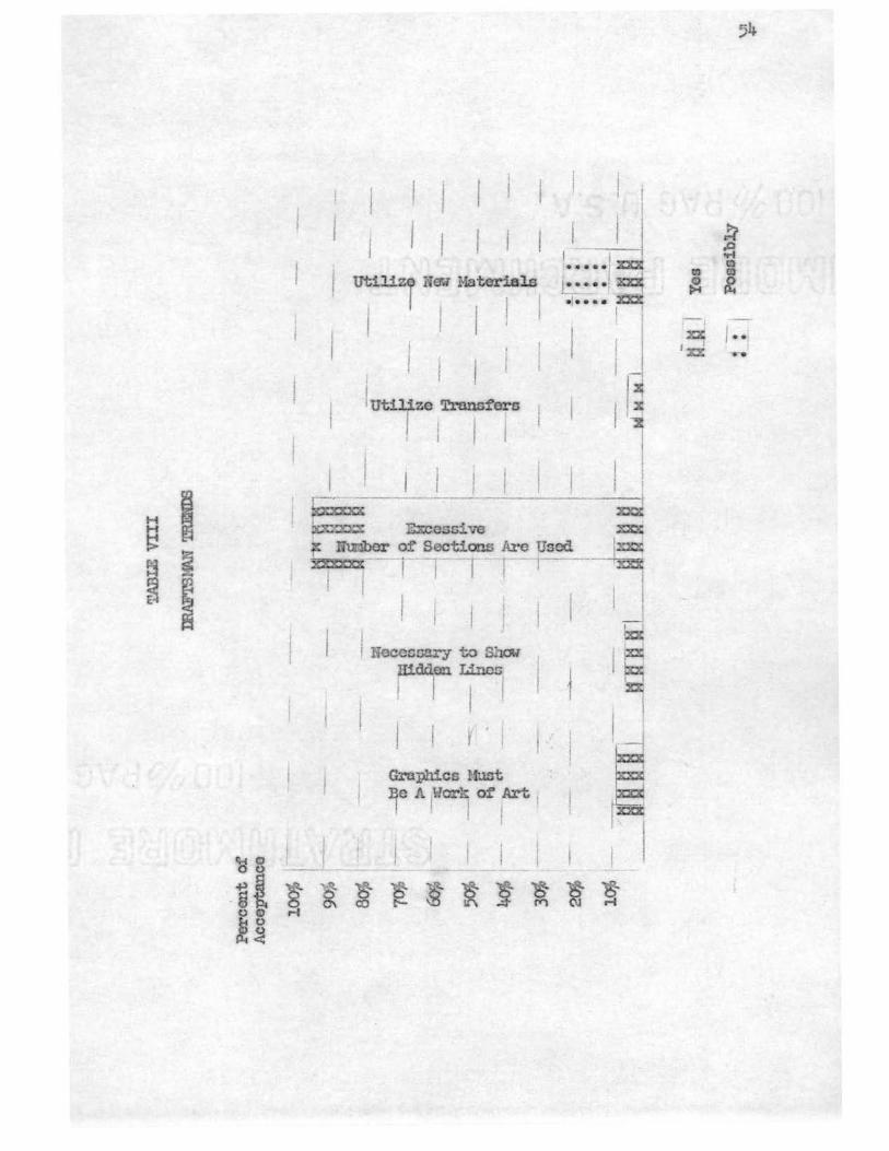
Utiliz Ife-.; Materials I I
1 I
lujze Trans~•
i j I I
~x;-;------· bt..~ Excest::i ve
! . I
I i I I ----! -I •••• •: x:xl4 :·····; ~ ·~1 ..... %XX
I ;
. I
I I~ I ~
! I
.xJ '. Nuriber of' Sections Are Used
~
1~ .... ; ~ -- ·-,-- 1 · - -r · r··- 1
! I , I
! ! I neccsoary to S ow
llidd.on Lines 1 ! I I i 1
r . I Graphics Uuot
~ IF -~
I
:qe A 1.war~ of Art 1
I I j ,~ l I j
-- - -
' ~ / ..
' n
55
14. Standard parts library is being used in uost industries.
15. Photod:revi g .... as not been accepted or utilized by industry.
16. Excessive Ullbers of sections are used to overillustrate a. part.
17. It is not deemed necessary to show hidden lines on a drawing
vhen cl.llri ty is not dop.;.""ndent upon their use.
T'.ae pre- stated conclusions are based on the Tables II, III, IV, V,
VI, VII and VIII cOT.ll)iled i'ron the survey in Appendix B.
V -III. Recormenda tions . The :follatting recOI:l!londations, based on
the research revealed by the industrial survey and personal intervievs,
are:
1. Further stud.i · s be nade to the di vision of time and the engineer
to draft ratio.
· 2 . EliJ:Jinate elaborate pictorial s on working draWin , "Reserve
the right to use pictorials and elaborate views in catalogues
and brochtn"e prosentations . "13
3. Adopt co:1riany standards to eet those of Aneric n Standards
' ~ Association and Mill tnry Standards Bureau.
4. Cross-sectioni r,; should be e:riployed only if clority or
und.erGtnnding is dcponde11t upon it and then only partial cross
soctionillG should be considered.15
5. Superfl uous views that la.ck dinensions or written instruction
thereon should be o:1itted.
13Personal Interview, Production I llustration Departnont H d, Phillips Petroleun Conpany, Bartlesville, Oklahoma, May 29,. 1962.
l.4i.1r1 tten Interview, Huey M. York, Dosign Drn:f'tsna , The EaglePicher Conpany, Joplin, ·lissouri, May 23, 1962.
15 Rau, A. R. , "How to Sinplify Engineering DrawinB, u The Iron Age, Decenber 27, 1958.
56
6. Delineation of COilllOnly used objects are substituted by the use
of synbols traced fron te pllltes .
7. Photodravti.ng should be realized C.."l equirn.ent revisions ond
research projc.cts developed before fol"tla l engineering drawings
er nad.e.16
8 . 'L"Jpin.g should replace fr o-hrnd lettering for extensive parts
list and lengthy inforr:Jative notes .
9. Fl"'eo- hand drawing should replace echanical drawing when the
situatio pornits*
10. Special reproduction papers, ouch an rJ.Ylars, sepias, and other
synthetics should be utilized when the situation pernits .
The followinz reco. enda io sand statenents uero extractad frw
written inter riews :::recoi vod with t e i d.ustrial survey.
''We would welco: e universal accepted sLplification standards .
Presently we are in the process of starting a rJ.a.n l which will, as
far as possible, follm, Ancrican Standards. ttl7
'Whenever applicable, our sta~ da.ros t..avo bee:i nade to conforn to
American Standard rec endations of dra 1ng and drafting room practices. 1118
''Thero is definitely a need for sinplii'ied drafting practices used
in industry. It would bo a sreat asset in savine t:..ne a .d ooney. 1119
·we do not have a standards nanual f'or :procedures} but ve do have
16(No author given), "That ' s A Photodra'W'ing?", The Kodak COI:1].)8ss, February, 1961, .Pl? · l-12 .
17wri tten Interview, Love, K.. B. , Chief Engineer, Rogers Ironvorks Cor.i:pany, Joplin, Missouri, June 8, 1962.
lt\vritten Intor'1iew, Neff, ,linde11, Illustrator, Phill ps Petroleum. Con:. ny, Bartlesville, Oklahor:i..'l, June 10, 1962.
19; ritton I terviev, Huey M. York, Desiga. Draf'tsmn, The EaglePicher Company, Jopl in, Missouri, May 23, 1962.
57
12.rmece..ssary fancies. ••21
nwe a1"e of the or,inion that simplification is good. up to a point ..
Uc think e~::trer:wl~;t ninJ>lifierl 6..raWinc lead.'3 t<") sho;> orrorc. •!22
~--There is no one).n~ ·to fu1af'tsoan ratio. uc.j
A thorough theoretical cfatdy or tt.e _;p:roblen is fa.ckine; therefore,
accepted by uoot ind.us.tries.
20tvri tte:n Interviet-1., Jlllen Aidan., Chief Draftsman, Oklahooa Natural Gas Co::rr.a:ny, !-fay 29, 1962.
Z'-·Writteu In:t.e:r-view, Cupps, Fate, Design Draft.mg Hand, Al-.icrada Pcrtroleu.m. Cor:1J13.ny., Tulsa,. Oklahoma 1 Jm'l:a 2, 1962.
'.BOOID3
Giesecke" Fredrick 3., Mitchell, ,U,,a, and Spencer, 11~.r Dr~w!.ntz;, ed. 'ii1c i-!;.101nillun. CoY..1.:9<-'l...l'.l:y :· 1958., pp. 1-2.
... l,i .,
Uoal:;.:, U. ].,. a."'ldR£rJ., A. R .. 1 rn:t~~lr~inJ~?3:.o.ctiC:_O, ed. Joh:,n. Wiley anrl Sous, 1953.
Kuller, K. K,~rl, El.ectro11i.cs Th."aft;Ln&, ed. McG:rt:i:w·Hill Book Con11any, Inc .. , 1962 7 i;i.' 163.
Pin·-o, E .. C. ~ Lo-vine;, E. P., anti .Hill, I. L., nescri:otiv-0 Gcouct:;:x, ed. '2he Nacnilla:u C~n:oru1.;y, J..956, p.. 1.
Anoricau Sta:uuai'Cls Association, Catalogue of' Auerican Standards, (Mo Aa:chot·s, lfo Pu'blishors Ci ,r::::rn) • ·
C nta logue of Hili tary S tauc1ards, Suporintenclcnt of Docuncnts ,, (I\fo Authors Given), 5th Edi t.ian., March, 1961.
PriHIODICA1~
Bayer, C. H., <!Pro, Case For and A~,inst Si1n2lified Dra:f'tuig, 0 Epczi.a9el"iJ?.££ Grauh:l.c~, :February, 1962.- 2:2, pp. 6-7.
BliJck; Berl D., 11Yievs of E:.'l!3i:neering Grap..riics, ~t Ro,:>rod.uction I.\1:µneer, 1961, pp. 23-21:..
Mille1·, Jorm. B .. , "Cox1., Case For and Aga.ins .. c. S1n.1)li:tier1 DraJ:.""til111, '' En~necrin~ G:..~ph,ici~, Febru&rJ, 1962:. 2:2, W• C--7.
. . .
Rau., A. H., uE'ow to Sinplify E!l(3;inoering Drewing,!? ~ ~ i\m, Docciibor 27, 1958.

s.:Uck:; I'1n.·\~1EJ L. ~ n~~11.T::t "(J~!i:t':fHl Ih:~a\wr"l11{~ ·S::7st,C:]/" 7 D.::::.i.i.r;tl un{~ Dr~1-fi.~i.11{~ l~e:,-.tiz, Octoi,cl·.,. J.{J6l, pp. 1-10.
(\lz) .t\1:t't!101~ Gi ,rc.rn)) ittJ::1frt '.c -n Pl11Jtc:x1:rcrirlz:f;?;'1 , Th~ I{o§.llJ; gp:-·1!}1!E,, I~'L":.:b:t;.~~Icry 1961;1 1):: ...... 1-12 ~

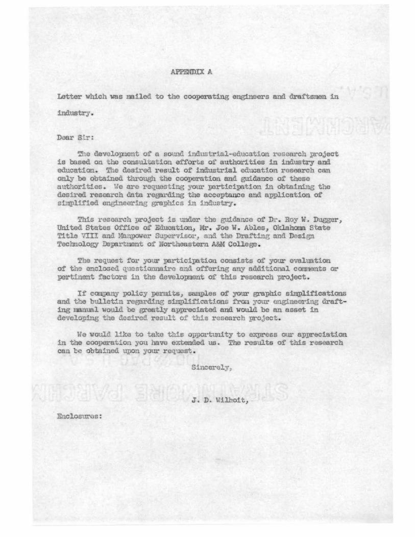
APPENDIX A
Letter which \."as nailed to the cooperating engineers and drai'tsmen 1n
industry .
D r s·r:
'!'ho devolo~ent of a sour industrial-education research project is based on tho consultatio efforts of authorities in ind stry rid eduction. The desired result of industrial ed cation research CQn only bo obtained through the cooperation and guidance of these uthori tics. ~!e ai·e req cstine your :participation in obtaining t e
desired research data regarding the acceptance and application of si. plificd cng.beerine phi.cs in i dustry.
This r sc rch project is '..U'lder the Q.rlda ce of Dr . Roy \ • Dugger, United States Office of Education, Mr. Joe W. Ables, Oklahocra State Title V.!II a d .-:a power Supcrviso .... ·, and t~ e raft i nti ond Design Technology Iepart1 nt of Uortheastorn A&M College.
T.e request for your :participation consists of your evaluation of' t l c enclosed. . ucntio ire end offering any additional cacnents or pcrti ent factors in tho developnent of this research project
If c . ~ny policy porni s, ples of' your graphic sinplif'ieations and t he bu1lct·n rcenrdi1e sicrplifications fro:a your cng:ineorine drafting nual oul.d be greatly ppreciatcd and would be an asset in devclo:ing t~e c~ircd result cf this r esearch project.
We would liko to t 1~0 this pportunity to e:,cprcss our appreciation in the cooperation you have extended us. The results of this rs arch can be obto:ned ur,en your roq st.
Sincerely_
J. D. Wilhoit,
· Enclosur s:
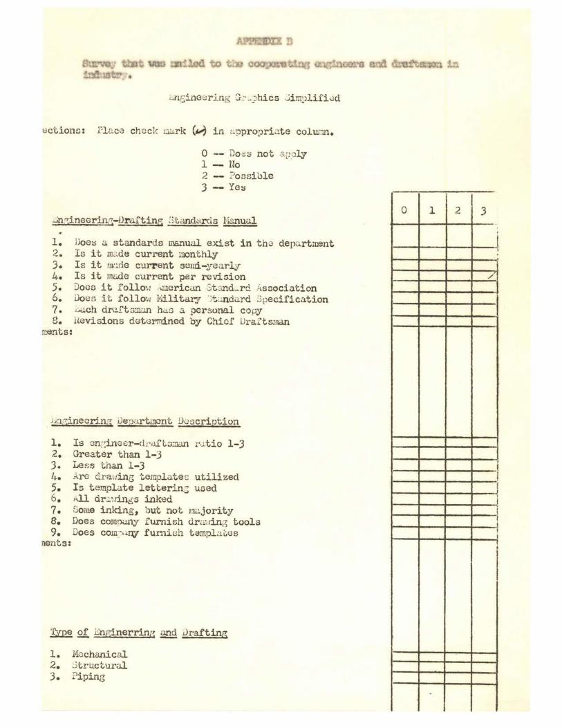
.i, . .:nt;;ineEJ r :ing G:.· -)hies ,:.;i mplif'i l3d
ections: Flr~ce che ck uarlc ~ in ,,;.ppropriJ.te colurm.
0 D Oi;:)S not ::LFoly 1 No ' ) ,._ Possible 3 -- Ye:;
.::;n;i;ineerin~-lJraftinr; .Stcl!ldd.rd.s Ma.nuul
1. Doe:s a. standards 1r1.s.nu.il exist in th;3 depc1.rtment 2. I s it m_o.de current monthly 3. Is it m.:~de current semi-y e arly 4. Is it m~e current per revision 5. Does it follO\J rlluericun 3t:.;',nd.~r d ;.l ssociation 6. ilo~n it follo\'~ Ivlilita:rJ '.>t :.i.ndJ.rd :3pecification 7. Du.Ch dri.!f t sm.:m hi.is s personal copy g. Hevisions det e rmined by Chief Draftsman
ments:
. L~1r:;inecrin;1 J eu::irt,ncnt Duscription
1. Is cn::inecr-cfri.lft.3.n.a.n r,.1tio 1-J 2. Greater than 1-3 J. Less than 1-3 l~. Are drattint; terIT9l at e~ util i zed 5. I s t empl ~te letterinJ used 6. ill dr2.:1ings inked ?. Some i nking, but not mc:.jority 8. Does comn,.my f urnish clr a.:1ing tools 9. Doe s corn~·xi.ny fuY"nish t ampl D.~es
nerrts:
~ of .i!;nginerrin£: ~ Jrafting
1. Mechanical 2. J t ru.cturnl J . Pi ping
0 1 2 3
~ '
/
'
-! l i ! l I I
I
.
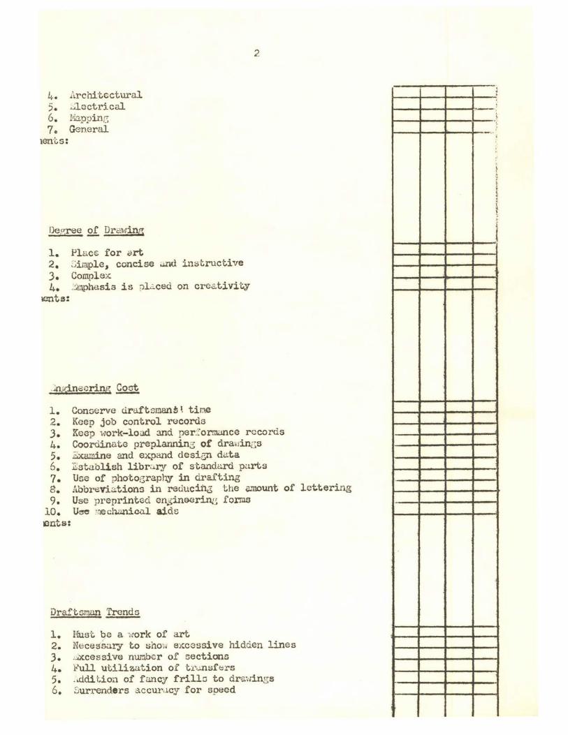
Li.. Architecturill 5. ;.:;lGctrical 6. NappL'1.G 7. General
1ent.s:
De ~rree of Drctwinz
1. Pl~C€ for ~rt 2. Simple, concise .md instructive J. Complex 4. .'.i!nphasis is pl c.ced on creativit,y
lC-"?lts:
1. Conoerve tlru.ftsman!l ~ tine 2. Keep job control r0cords
2
J. Keap work-load 3.nd per:::.'or:rrumce records 4. Coordinate preplarurl.n~ of dra,iincs 5. i;xam.ine and expand desiGil du.ta 6. 1 sta.blish libru.ry of standc.:.rd parts ?. Use of photoz raphy in drafting e. Abbreviations in reducinJ the amount of lettering 9. Use preprinted en$inoorin.t1 forms
10. U:,e mech..:J.nic.:i.l aids ~nts:
Draft.sman Trends
l. Must. be a work of art 2. Neces·sary t.o ~ho;J e1wcssi ve hidden lines J. ,.::Xcessive n1E.1ber of sections 4. l ull utilization of t.:c..m::ift;!'S 5. ..ddit ion of fancy frilla to dra:wings 6 • .Surrenders a.ccur.icy for speed
:: 1-~_..~~i-~~-~ .
t---+--1--~--} ' '
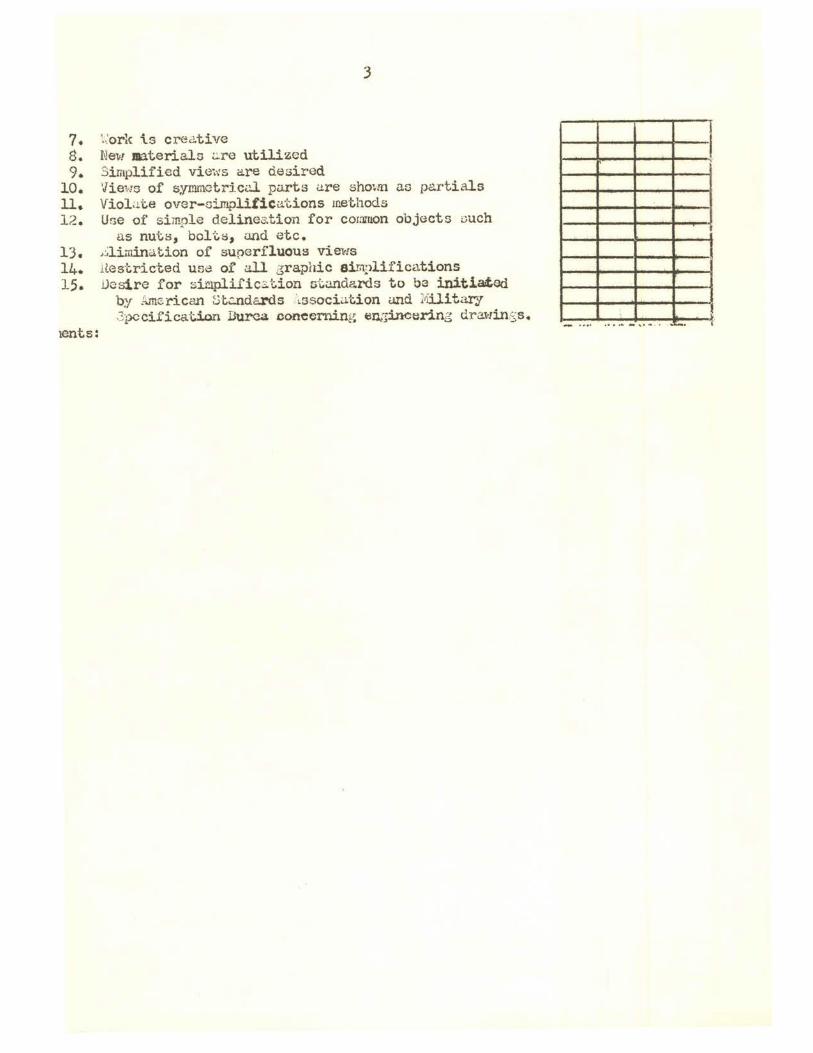
3
7. ~:ork is crec1tive 8. New mteria.ls ..:.re utilized 9. 3implified views are desired
10. 'Jiews of syrnrnctriccl. parts are sho\m as p&rtials 11. Violu.te over-oi.mplifica'i:.ions methods 12. Une of simple delinea.tion for common objecto ouch
us nuts, boltti, and etc. 13. ,~lirnination of superfluous views 14. H.estricted us~ of all 3raphic sim:>lifica.tions 15. Desire for sinlplific:,.tion r;;t,undards to ba initiated
by l.me:.rican ~t..'.a.Ildards d3sociat,ion d.!ld 11.iilitar--.1 3pc cif'i cat.ion Durca concerning en_;:;inceri.ng dra.win; s.
ients:
-~
APPEJ:IDIX C
List of persons who partiCi!Xl ted in the sm-v,ey.
All.en, Aiden, Drafting Read, Oklaho I{atural Gas Com:peny, Oklahona City, Oklahoma.
Autry, Vann, Draftsmn, Capitol Steel Conpany, Noman, Ok.lahom.
Booth, 11:itt"J, Engineer Aid, Goodrich Conpany, Miani, Oklahoma.
Burnhan, Jones L., Draftsnan, Fife Mnnuf'acturing Ca pe.ny, Oklahoon City, Ok:Jmonti.
Clark, Marion E., Draftsnan, Oklahona Geological Survey Cc:npmy, Oklnhom City, Okla.ho
Ctuminghan, Joe, Draf'tsnan, Capitol Steel C~ny, Oklahona City, Oklaho.ca ..
Cupps, Fate, Design Drafting Head, Ar eracla Petrol.ou::i Co:cipany, Tulsa, Oklahona.
Esslinger, R. T., Chief' Dra:f'tsnan, Acn.o Iron Works, Joplin, Missouri.
Ford, Dwight, Draftsnan, Cha:iplin Oil Con:pany, Oklahona City, Oklahot1a ••
Fourier, E·~rl, Design D:raftS!l8.n, George E. Failing Cor:1pru1y, Enid, Oklah0t1a.
Freline, Nick, Production Illustration Read, Phillips Petrol.eU?J COllI)!llly, Bartlesville, Okla.hona
Gobrs, Tb.eodore, Chief Draftsmn, ~err-McGee Oil Con:pany, Oklahono City, Oklahona.
Grubbs, Seth, Engineer, OklahcrJa Iiaturcal Gns Co :IX:lrlY, Tulsa, Oklahoma.
Harris, Donald, DraftS!lEln, D-X Sunray Oil Co:ipany, OklahOl:18 City, Oklahom.
Harris, Douglas, Dra_-f'tsmn, 01'"..lahona City, Oklahom.
Ricks, ~rrion, Instructor, 01'",.J.ahor.ia Cit-; University , Oklahcca City, Oklahom.
Hiret, J. W ., Engineer, Oklo.hona Gas and Electric CotI];nllY., Enid, Okl.ahona.
Hoel, Cl.yde, Drafts1:J:1n, Tinker Air Base , Midwest City , Oklahona.
Lee, Gary, Draftsnan, Kipp-Roderts CoI:I.PWIY, Ui ani., Oklahor:a.
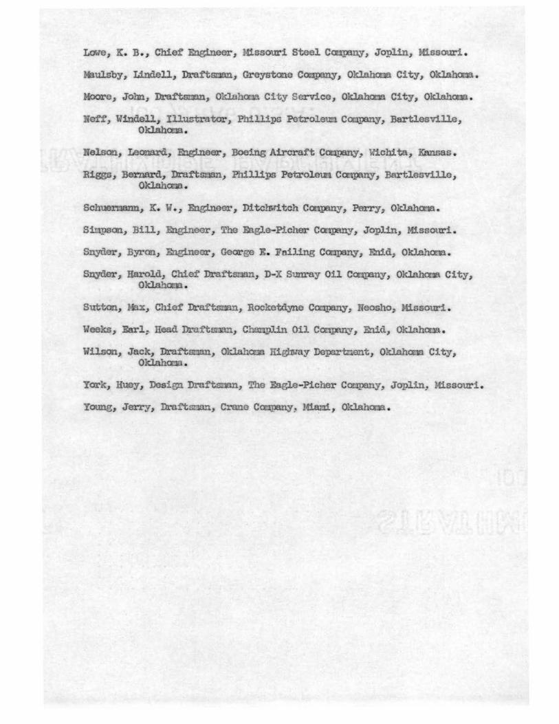
Lawe, K. B., Chief Engineer, Missouri Steel C0t1.piny, Joplin, Missouri.
Maulsby, Lindell, Draftsman, Greystone Com,pany, Oklahoma City, Oklahoma.
City, Oklahaoa.
Noff, 'Windell, Il1ustrator, Phillips Pe-troleuo. Con.pmy, Bartlesville, Oklaha:ia .
el.son, Leonard, Engineer, Boeing Aircraft Com:peny, Wichita, Kansas.
Biggs, Bernard, Drai'tSt1Bn, Phillips Petroleun Ccnl)E\ny, Bartlesville, Oklahana .
Scbuel.'rlmlll, .K. W., Engineer, Ditc!1Witch Campany, PeITy, Oklahcria.
Sittpson, Bill, Engineer, The F.agle-Picher CCl"l.,l)a!l.Y, Joplin, Missouri.
Snyder, Byron, Engineer, George E. Failing CO!JI>anY, Enid, Oklahoma.
Snyder, Harol.d, Chief Draf'tSill.tn, D-X Sunray Oil Co.-:qnny, OklahO!la City, OklahOI.Tl •
Sutton, l , ChiGf Draftsman, Rocket.dyne Caa,pa:ny, ?Jeosho, Missouri.
Weeks, .Earl: Head Dra:ftf!Qa,!l, Charl!>lin Oil ConIBDY, Enid, Oklahooa.
Wilson, Jack, Dra:rtsnan, Oklnhooa Hightray Departnent, Oklahona City, Oklahcna .
York, Huey, Design Draftstl!ln, The Eagle-Picher Coripany, Joplin, Missouri.
Young, Jetty, Dro.:rtsrum, Crane Con:pany ~ Mi.am, Oklaha:ia .
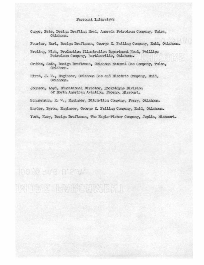
Personal lntervieus
C:a;ppg, Fate, Design Drafting Read, Amerada Petroleum. Company, Tulsat Oklahona.
FotU:'1.er, ])n-1, Design Draf'tsnan, George E. Failing Conpany., Enid, O't.lahotla.
Freling, Nick, Production Illustration DeJ;Ert.i.,-ient Read,, Phillips Petroleum Company, Bartlesville, Oklahoma.
Grubbs, Seth, Design .Dra.i'tsman, 0~ Natural Gas Campany,. Tulsa, Oklahor.1a •
1Iirst: J. \!.., Enginoor, Oklah0".18 Gns and Electric Company, En.ids OklahomA.
Johnson, Loyd, Educational Director, Roeketdyne Division o:f North Anericoo AViation, Ns-osho, Missouri .
Schuermann, K. W. , Eng:ineer-~ Di tchwi tch Conp:tny, Perry, Oklahoma .
Snyder, .B31"on., Engineer, George E. li'ail.ing Company, Enid, Oklahaua .
York, :a:uey, Design Draftsman, The Eagle-Picher Coapany, Joplin, Missouri.