Embed Size (px)
Citation preview

SIMPLIFIED BUILDING MODELS EXTRACTION FROM ULTRA-LIGHT UAVIMAGERY
Olivier Kung1, Christoph Strecha1,2, Pascal Fua1, Daniel Gurdan3, Michael Achtelik3, Klaus-Michael Doth3, Jan Stumpf3
EPFL-CVlab1, Pix4D LLC2, Ascending Technologies GmbH3
KEY WORDS: UAVs, Photogrammetry, 3D Reconstruction, Simplified Building Models
ABSTRACT:
Generating detailed simplified building models such as the ones present on Google Earth is often a difficult and lengthy manual task,requiring advanced CAD software and a combination of ground imagery, LIDAR data and blueprints. Nowadays, UAVs such as theAscTec Falcon 8 have reached the maturity to offer an affordable, fast and easy way to capture large amounts of oblique imagescovering all parts of a building. In this paper we present a state-of-the-art photogrammetry and visual reconstruction pipeline providedby Pix4D applied to medium resolution imagery acquired by such UAVs. The key element of simplified building models extraction isthe seamless integration of the outputs of such a pipeline for a final manual refinement step in order to minimize the amount of manualwork.
1 INTRODUCTION
Virtual globe visualization software such as Google Earth(Google,2011a) are becoming increasingly popular, both on desktop andmobile platforms. They enable many applications in the fields ofnavigation, tourism, but also city and land planning. In additionof displaying detailed 2D vectorial and raster maps on top of dig-ital elevation models, modern virtual globes have the ability torender 3D building models.
These viewers often stream content over the web, for that reasonthe building models need to have the lowest number of polygonsas possible. It is also a matter of processing power, as visual-ization of large cities implies the rendering of a huge amount ofpolygons by the viewer. Finally, to make the most visual sense,these models should capture also the semantics of the building,its main characteristics and properties. In other words it meansthat the polygons should correspond to the human understandingof a building: facades, roof, windows, balcony and so on. TheCityGML standard (Fan et al., 2009) represents objects in vary-ing levels of detail (LOD), where level 1 and 2 correspond to boxmodels without and with roofs, as often encountered on GoogleEarth. Level 3 includes additional architecture details that aresometimes present on specific buildings such as landmarks onGoogle Earth.
As for today, modeling of buildings is usually a difficult lengthymanual task done using CAD software. Data is usually acquiredusing a combination of total station, terrestrial laser scanners,blueprints, airborne LIDAR and imagery (Georgeta Pop, 2008,Karantzalos and Paragios, 2010, Haala and Brenner, 1997) . Mostof these solutions are either very expensive, lengthy, or requireadvanced knowledge in these fields. There have been multipleapproaches which proposed to automate the process of generat-ing level 1 and 2 building models using various algorithms basedpurely on images. However, these techniques are usually lim-ited to very simple buildings’ shape or to over simplified mod-els(Debevec et al., 1996, Zebedin et al., 2008, Zhou and Neu-mann, 2010, Guo et al., 2008, Woo et al., 2008, Melnikova andPrandi, 2011, Nan et al., 2010). At the best of our knowledge, thiscrucial step of generating fully automatically LOD 3 buildings isnot yet solved, and human intervention is still required.
We propose a workflow that drastically reduces the amount anddifficulty of manual labor both in the acquisition process and in
the modeling process. Based purely on images, it removes theneed for blueprints or LIDAR data. Images are aquired by au-tomated UAV, making the whole process fast, easy to deployand affordable, and ensuring a full coverage of the building in-cluding rooftops and facades. These images are then automati-cally processed, outputting a LOD 1 model. Moreover, the posi-tions of the images and dense 3D cloud of points are also gener-ated. These two elements are seamlessly integrated in the CADsoftware Google Sketchup(Google, 2011b), and this integrationgreatly minimizes and simplifies the manual tasks to achieve aLOD 3 model.
The three main elements of this workflow, shown on figure 1, are:
• Acquisition of images using automated UAVs
• Fully automated image processing and LOD 1 model extrac-tion
• Seamless integration in CAD software
Capture of large set of images at all possible views is a per-fect task for micro Unmanned Aerial Vehicles (UAV). Fully au-tonomous UAV have recently become commercially available atvery reasonable cost for civil applications. The advantage ofthese aircrafts is their ease of deployment and retrieval. More-over, UAV such as the AscTec Falcon 8 have the capability oftaking oblique to horizontal imagery, allowing them to captureimages all around a building at different heights.
Recent advances in photogrametry and computer vision have al-lowed to take full advantage of large set of images based onStructure From Motion and Multiview stereoscopy(Strecha et al.,2011). One key element of these algorithms is their ability toautomatically recover the exact position and orientation of largesets of images, together with the parameters of the camera justby analyzing and matching the content of the images and byperforming a bundle adjustment on those matches(Triggs et al.,2000). Taking these parameters as input, dense matching algo-rithms(Furukawa and Ponce, 2009, Furukawa et al., 2010, Fu-rukawa et al., 2011) find as many correspondences as possiblein the images to provide a very dense cloud of point. A LOD 1building model is then automatically extracted from this cloud ofpoints. Pix4D(Pix4d, 2011) is a company which provides such a

Figure 1: Workflow of our method
service applied to UAV imagery which takes into account geolo-calization of the cameras using the GPS tags and introduction ofGround Control Points for better geolocalization.
Modern Computer-aided design (CAD) software such as GoogleSketchup(Google, 2011b) offer powerful and intuitive tools formodeling buildings. However they lack fully automated imageprocessing algorithms to register the images to the scene and gen-erate an automated dense cloud of points. Starting with the au-tomatically computed LOD 1 building model, together with theoverlaid cloud of points reduces greatly the modeling time forhigher level of details. Furthermore, displaying the registered im-ages allows the finest details to be modeled, together with a veryconvenient way to texture the model by a simple projection.
This paper is organized as follows. In section 2, the image ac-quisition using an AscTec Falcon 8 and a swinglet CAM arediscussed. In section 3 the automated image processing algo-rithms are explained. Section 4 presents the seamless integrationof the results of the algorithms with the CAD software GoogleSketchup. The workflow is demonstrated in section 5 on four dif-ferent datasets, three taken by the AscTec Falcon 8 and one witha swingletCAM by Sensefly. We also discuss for each of themthe results of the different steps.
2 IMAGE AQUISITION
In traditional photogrametry, the number of images is minimizedas it adds tedious work to calibrate, register and use for the mod-eling step. With the advent of fast fully automated image pro-cessing, this paradigm is not valid anymore. A larger number ofimages equals an increased likelihood of a precise automatic reg-istration. One of the requirement of these algorithms is a largeoverlap in the order of 60% to 80% between the images. Asdigital cameras equipped with sufficient memory are nowadaysubiquitous, capturing a large amount of images is not a technicalproblem anymore.
Images taken from the ground are inherently unable to captureroof structures. On the other hand, planes and helicopter are waytoo complex and expensive to deploy for capturing images from asingle building. UAVs equipped with a camera are the perfect fitto automatically capture large amounts of images including roofstructures and facades in an easy and affordable way.
2.1 AscTec Falcon 8
The AscTec Falcon 8 produced by Ascending Technologies GmbH,Germany, is an 8 rotors flying platform displayed on Figure 1. ItsSONY NEX-5 system camera records 14MP images. Due to theunique design of the AscTec Falcon 8 the camera is able to facecompletely down, horizontal and completely up, without any of
the rotors compromising the image. The Falcon 8 has a dedi-cated software which handles the flight plan, allowing it to circlearound a point of interest with tilting of the camera to point to thesame target. The mission planning has been automated for theapplication of generating building models. It can easily be doneby the operator while the UAV is airborne with some simple stepsusing the telemetry display of the mobile ground station only. Thefollowing steps are required before the UAV automatically takesall images required for generating a building model. First, the pi-lot has to fly roughly above the center of the building of interest,operationg the AscTec Falcon 8 in GPS assisted mode and usingthe camera pointing down to determine when the UAV is hoveringabove the building. After pressing a button on the mobile groundstation the UAV must now be flown away from the building, untilthe whole building is visible on the camera image. Also the de-sired flying altitude and camera orienation can be selected in thisstep. After pressing a button again the operator is asked to enterthe number of photos desired, which are then evenly distributedon a circle around the building. After that, pressing GO makesthe AscTec Falcon 8 take the first photograph on its current lo-cation and then automatically take all photos on its way aroundthe building. As the whole process can be done without a laptopcomputer it is easy for the operator to change their position in or-der to keep the UAV in visual range throughout the flight, whichis required by law in most countries.
2.2 swingletCam
The swinglet CAM is an electrically-powered 500-gram flyingwing including a full-featured autopilot and an integrated 12 MPstill camera. Its low weight combined with its exible-foam air-frame makes it particularly safe for third parties as it has approx-imately the same impact energy as a medium sized bird. It islaunched by hand, which makes it particularly quick to deploy.
3 IMAGE PROCESSING
UAVs are equipped with GPS, gyroscopes and accelerometerswhich are logged during the flight. Once back on the ground,a software is dedicated to correctly tag the images with GPS andorientation information. The GPS information has a few metersof inaccuracy. By analyzing the images, we can recover the trueposition of the camera, also called Calibration step. Once the po-sitions are know, we can match more pixels across the images togenerate a 3D cloud of point in a step called Dense Matching.The cloud of point is then projected on the z axis to easily detectthe facades and compute the building’s main directions. From thefacade model, the minimum and maximum height in this area canbe found and a box model is then extracted. All of these steps arefully automated and don’t require any extra parameter tunings orother manual step.
3.1 Structure From Motion
In this paper we use the commercial service offered by Pix4D(Pix4d,2011). It takes as input roughly geotagged images, and outputsthe recomputed position of the images together with the parame-ters of the camera. It is presented in form of a web-based servicethat can automatically process up to 1000 images, is fully auto-mated and requires no manual interaction. Ground control pointscan be added for more accurate geo referencement. The softwareperforms the following steps:
• All uploaded images are analyzed individually for keypoints.On a second step these keypoints are compared across im-ages to find matching ones. Most well known in computervision is the SIFT feature matching (Lowe, 2004). Studieson the performance of such feature desciptors are fiven byMikolajzyk et.al (Mikolajczyk and Schmid, 2002). We usehere binary descriptors, which are very efficient and fast tomatch (Strecha et al., 2011).
• The matching points as well as approximate values of theimage position and orientation provided by the UAV autopi-lot are used in a bundle block adjustment (Hartley and Zis-serman, 2004) to recompute the exact position and orienta-tion of the camera for every acquired image.
• Based on this reconstruction, the matching points are veri-fied and their 3D coordinates calculated. The geo-referencesystem is WGS84, based on GPS measurements from theautopilot during the flight.
A report is generated giving statistics about the calibration andgeo referencement.
3.2 Dense Matching
The cloud of points generated in the calibration step consists onlyof keypoints that were successfully matched and verified alongmultiple images. There are potentially many more matches whichcan be verified, producing a much more dense cloud of points. Inthis work, we use the approach by (Furukawa and Ponce, 2009,Furukawa et al., 2010, Furukawa et al., 2011). It is composedof first a image clustering part (CMVS), followed by the actualdense matching algorithm (PMVS). CMVS takes the output ofPix4D as input, then decomposes the input images into a set ofimage clusters of manageable size. These clusters are then passedto the PMVS software. The PMVS algorithms is based on ori-ented patches and are computed by iteratively following thesethree steps:
• Match: edge features from the images are matched alongepipolar geometry and form potential candidates
• Expend: spread the initial matches to nearby pixels and ob-tain a dense set of patches
• Filter: visibility and smoothness constrains are applied toremove matches
The output of this algorithm is a set of points together with theassociated normals.
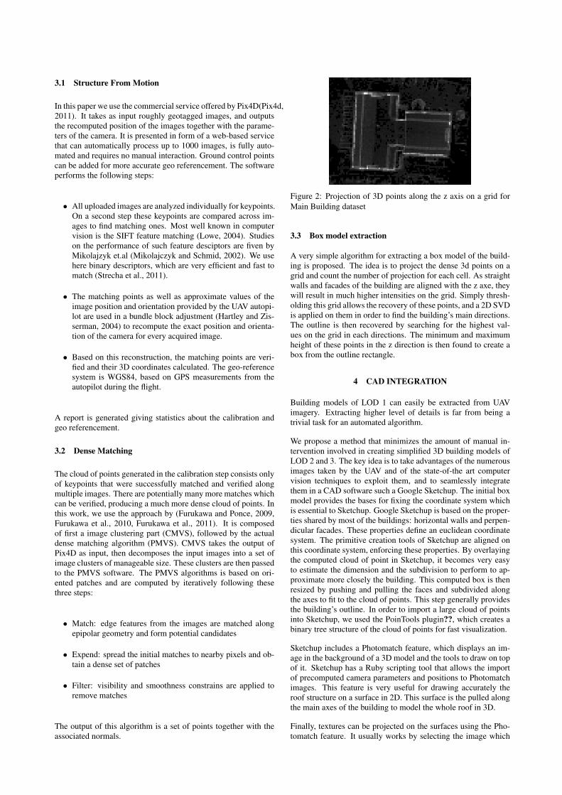
Figure 2: Projection of 3D points along the z axis on a grid forMain Building dataset
3.3 Box model extraction
A very simple algorithm for extracting a box model of the build-ing is proposed. The idea is to project the dense 3d points on agrid and count the number of projection for each cell. As straightwalls and facades of the building are aligned with the z axe, theywill result in much higher intensities on the grid. Simply thresh-olding this grid allows the recovery of these points, and a 2D SVDis applied on them in order to find the building’s main directions.The outline is then recovered by searching for the highest val-ues on the grid in each directions. The minimum and maximumheight of these points in the z direction is then found to create abox from the outline rectangle.
4 CAD INTEGRATION
Building models of LOD 1 can easily be extracted from UAVimagery. Extracting higher level of details is far from being atrivial task for an automated algorithm.
We propose a method that minimizes the amount of manual in-tervention involved in creating simplified 3D building models ofLOD 2 and 3. The key idea is to take advantages of the numerousimages taken by the UAV and of the state-of-the art computervision techniques to exploit them, and to seamlessly integratethem in a CAD software such a Google Sketchup. The initial boxmodel provides the bases for fixing the coordinate system whichis essential to Sketchup. Google Sketchup is based on the proper-ties shared by most of the buildings: horizontal walls and perpen-dicular facades. These properties define an euclidean coordinatesystem. The primitive creation tools of Sketchup are aligned onthis coordinate system, enforcing these properties. By overlayingthe computed cloud of point in Sketchup, it becomes very easyto estimate the dimension and the subdivision to perform to ap-proximate more closely the building. This computed box is thenresized by pushing and pulling the faces and subdivided alongthe axes to fit to the cloud of points. This step generally providesthe building’s outline. In order to import a large cloud of pointsinto Sketchup, we used the PoinTools plugin??, which creates abinary tree structure of the cloud of points for fast visualization.
Sketchup includes a Photomatch feature, which displays an im-age in the background of a 3D model and the tools to draw on topof it. Sketchup has a Ruby scripting tool that allows the importof precomputed camera parameters and positions to Photomatchimages. This feature is very useful for drawing accurately theroof structure on a surface in 2D. This surface is the pulled alongthe main axes of the building to model the whole roof in 3D.
Finally, textures can be projected on the surfaces using the Pho-tomatch feature. It usually works by selecting the image which

Figure 3: EPFL BC building: bundle block adjustment mesh, colorized dense matching 3D points, geolocalized refined textured model
is facing the most a selected surfaces in order to minimize distor-tions, followed by a projection involving a homography from theimage to the surface.
5 RESULTS AND DISCUSSION
We tested this workflow on different datasets: three taken with anAscTec Falcon 8 octocopter and one using a swingletCam wing.The main advantage of the octocopter is the ability to program thetilt the camera during the flight planning, thus allowing to targetthe building during the capture. The swingletCam wing has afixed camera and needs to perform acrobatic figures in order totake oblique imagery. As is it much harder to control, multiplepasses are done, thus capturing many more images.
5.1 Ascending building
In this flight 138 images are captured by the AscTec Falcon 8.Three images from this dataset are show on figure 1 The flightplan is a circle with the camera tilting to target the building. Amedian of 4111 keypoints per images are found. After the match-ing, 131079 3D points are computed and used in the bundle ad-justment. After this step, all images are successfully registered,with a mean reprojection error of 0.7 pixels. The overlap be-tween the images was sufficient for a successful calibration step.The computation of this first step by Pix4D was under an hour,including the uploading time.
The dense matching outputs over 400’000 points, colored anddisplayed in figure /refprocess. The points are extremely denselysampled, which gives the illusion of texture from far away. Glob-ally, most of the parts have been correctly reconstructed. Thisbuilding has two main difficulties for dense matching: very repet-itive texture on the roof and white uniform walls. Repetitive tex-ture can lead to errors such as floating points above the surface.The uniform walls are poorly textured, and thus consistency can-not be checked and no 3D point is computed. There are enoughpoints recovered on the balcony to estimate its size, however thereconstruction is too sparse to accuratly estimate objects such asa table on the balcony. There is a bit of noise in the reconstructionwhich we visually estimate in the orders of 5 to 10 centimeters.
A box model is correctly estimated by projecting the points on agrid and computing the main directions. The modeling processstart from this box. From a front facing image, the roof shapecan be approximated with segments drawn on a registered imageon the front of the box. Extruding this surface models the wholeroof. Other elements of the buildings such as the balcony are ap-proximated by adding primitives to cover all computed dense 3Dpoints. In order to texturize the model, registered images facingthe different walls are chosen in order to minimize the distortionsand simply projected on the selected faces.
This model was submitted for inclusion on Google Earth, andsuccessfully accepted after review. It is now publicly visible atKonrad-Zuse-Bogen 4, 82152 Krailling, Germany.
5.2 Main house and side house
In the two flights, 36 images were captured by the AscTec Falcon8 for each dataset. The flight plans are a circle with the cam-era tilting to target the buildings. A median of 9513 keypointsper images are found. After the matching, 118334 3D points arecomputed and used in the bundle adjustment of the main build-ing shown on figure 4, and 70176 for the side building in figure5. After this step, all images are successfully registered, with amean reprojection error of 0.6 pixels in both cases. The overlapbetween the images was sufficient for a successful automatic cal-ibration step. The computation of this first step by Pix4D wasunder an 20 minutes, including the uploading time.
The dense matching outputs over 200’000 points, colored anddisplayed in figure 4 and 5. The roofs got extremely well recon-structed, with almost no floating pixels due to repetitive texture.The facades were a bit more problematic, due to slightly overex-posed images resulting in poor photometric consistency checksin the dense matching. However the edges between the facadeswere well reconstructed, allowing the understanding of the build-ing’s structure. The box model was successfully extracted in bothcases as can be seen in the figures.
Modeling these building was a more challenging task, as they arecomposed of many geometrical overlapping parts. The manualsteps were first to segment the starting box at places were the fa-cade edges present in the overlaid cloud of point. Using the Pushand Pull tools, the segmented parts can the easily be adjusted tofit the points on the facade. Once the outline of the building iscorrectly set, the roof is drawn on top of registered images andthen pulled along the building’s main directions.
One additional difficulty in these two datasets is that due to theshape of the building, not all parts can be seen in the images. TheUAV should fly twice around the building at two different heightsto capture all the details and texture. It is also interesting to notethat vegetation is very challenging and that the 3D points on treeswere often not computed.
5.3 EPFL BC building
In this flight 458 images were captured by the senseFly Swinglet-Cam. The flight plan is consists of multiple passes over the build-ing and its aera performing acrobatic figures to acquire obliqueimagery. A median of 1980 keypoints per images are found. Af-ter the matching, 377983 3D points are computed and used inthe bundle adjustment, visible in figure 3. After this step, 454images are successfully registered, excluding four blurry images,
with a mean reprojection error of 0.9 pixels. The overlap be-tween the images was sufficient for a successful calibration step.The computation of this first step by Pix4D was under two hours,including the uploading time.
The dense matching step resulted in several millions of pointsfor the whole covered area, and around 200’000 for the building.Because of the repetitive parts of the texture on the roof, somecluster of pixels were floating a few meters above the roof sur-face. Facades are very sparsely reconstructed, mostly due to thefact that the images were not fully oblique and the reflective na-ture of the large windows. The box model however fitted nicelythe facades. The manual part consisted mostly of creating theprimitive for the roof top.
6 CONCLUSIONS AND FUTURE WORK
We presented in this work an approach for extracting simplifiedbuilding models from UAV imagery. Our first remark is to pointout the maturity of automated algorithms for registering and cali-brating large amount of oblique images. This creates a paradigmshift in the photogrametry community, where the goal now is totake as many images as possible instead of selecting a very lim-ited number of points of view. This shift makes UAVs perfectlysuited for the image acquisition process, as they can easily flyaround buildings and take numerous images of all angles.
The dense matching step generates a large amount of measure-ments. However, the quality still depends greatly on the textureof the surfaces to reconstruct. The output is relatively noisy, notuniformly sampled and contains a few outliers. This is not anissue for box model of building, but makes higher level of de-tail modeling not a trivial task for automated algorithm. More-over, simplified building models are related to the semantics ofthe building, a problem which is still far from being solved.
In contrast, we propose to seamlessly include the results of cali-bration and dense matching in the process of refining a box model.This makes the modeling of a building using only imagery pos-sible and minimizes the amount of manual work. Future work isneeded to assess the quality of these reconstruction by compari-son with blueprints for example.
REFERENCES
Debevec, P. E., Taylor, C. J. and Malik, J., 1996. Modeling andrendering architecture from photographs: a hybrid geometry- andimage-based approach. In: Proceedings of the 23rd annual con-ference on Computer graphics and interactive techniques, SIG-GRAPH ’96, ACM, New York, NY, USA, pp. 11–20.
Fan, H., Meng, L. and Jahnke, M., 2009. Generalization of 3dbuildings modelled by citygml. In: W. Cartwright, G. Gartner,L. Meng and M. P. Peterson (eds), Advances in GIScience, Lec-ture Notes in Geoinformation and Cartography, Springer, BerlinHeidelberg, pp. 387–405.
Furukawa, Y. and Ponce, J., 2009. Accurate, dense, and robustmulti-view stereopsis. IEEE Trans. on Pattern Analysis and Ma-chine Intelligence.
Furukawa, Y., Curless, B., Seitz, S. M. and Szeliski, R., 2010.Towards internet-scale multi-view stereo. In: CVPR.
Furukawa, Y., Curless, B., Seitz, S. M. and Szeliski,R., 2011. Clustering views for multi-view stereo.http://grail.cs.washington.edu/software/cmvs.
Georgeta Pop, Alexander Bucksch, B. G., 2008. 3d buildingsmodelling based on a combination of techniques and methodolo-gies.
Google, 2011a. Google earth. http://earth.google.com.
Google, 2011b. Sketchup. http://sketchup.google.com.
Guo, B., Zhang, Z., Shao, Y. and Li, Q., 2008. Building extractionbased on dense stereo match and edison algorithm. In: ISPRS08,p. B3b: 405 ff.
Haala, N. and Brenner, C., 1997. Generation of 3D city mod-els from airborne laser scanning data. EARSEL Workshop onLIDAR remote sensing of land and sea pp. 105–112.
Hartley, R. I. and Zisserman, A., 2004. Multiple View Geometryin Computer Vision. Second edn, Cambridge University Press,ISBN: 0521540518.
Karantzalos, K. and Paragios, N., 2010. Large-scale building re-construction through information fusion and 3-d priors. GeoRS48(5), pp. 2283–2296.
Lowe, D. G., 2004. Distinctive image features from scale-invariant keypoints. Int. J. Comput. Vision 60, pp. 91–110.
Melnikova, O. and Prandi, F., 2011. 3d buildings extraction fromaerial images. In: HighRes11, pp. xx–yy.
Mikolajczyk, K. and Schmid, C., 2002. An affine invariant in-terest point detector. In: Proceedings of the 7th European Con-ference on Computer Vision-Part I, ECCV ’02, Springer-Verlag,London, UK, UK, pp. 128–142.
Nan, L., Sharf, A., Zhang, H., Cohen-Or, D. and Chen, B., 2010.Smartboxes for interactive urban reconstruction. ACM Trans.Graph. 29, pp. 93:1–93:10.
Pix4d, 2011. Hands free solutions for mapping and 3d modeling.http://www.pix4d.com.
Strecha, C., Bronstein, A., Bronstein, M. and Fua, P., 2011. LDA-Hash: improved matching with smaller descriptors. IEEE Trans-actions on Pattern Analysis and Machine Intelligence.
Triggs, B., McLauchlan, P., Hartley, R. and Fitzgibbon, A., 2000.Bundle Adjustment – a Modern Synthesis. In: Vision Algo-rithms: Theory and Practice, pp. 298–372.
Woo, D., Nguyen, Q., Tran, Q., Park, D. and Jung, Y., 2008.Building detection and reconstruction from aerial images. In:ISPRS08, p. B3b: 713 ff.
Zebedin, L., Bauer, J., Karner, K. and Bischof, H., 2008. Fusionof feature- and area-based information for urban buildings model-ing from aerial imagery. In: D. Forsyth, P. Torr and A. Zisserman(eds), Computer Vision ECCV 2008, Lecture Notes in ComputerScience, Vol. 5305, Springer Berlin / Heidelberg, pp. 873–886.10.1007/978-3-540-88693-864.
Zhou, Q.-Y. and Neumann, U., 2010. 2.5d dual contouring: a ro-bust approach to creating building models from aerial lidar pointclouds. In: Proceedings of the 11th European conference on com-puter vision conference on Computer vision: Part III, ECCV’10,Springer-Verlag, Berlin, Heidelberg, pp. 115–128.
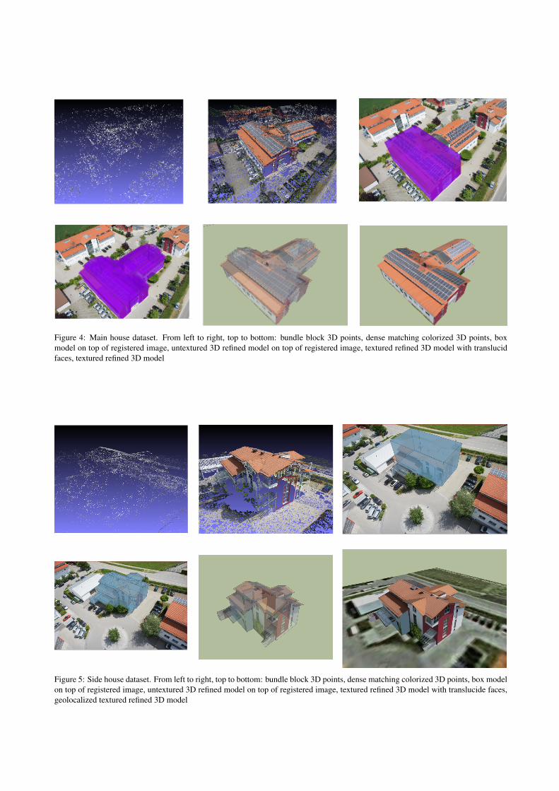
Figure 4: Main house dataset. From left to right, top to bottom: bundle block 3D points, dense matching colorized 3D points, boxmodel on top of registered image, untextured 3D refined model on top of registered image, textured refined 3D model with translucidfaces, textured refined 3D model
Figure 5: Side house dataset. From left to right, top to bottom: bundle block 3D points, dense matching colorized 3D points, box modelon top of registered image, untextured 3D refined model on top of registered image, textured refined 3D model with translucide faces,geolocalized textured refined 3D model