Embed Size (px)
Citation preview
Simplified Mechanical Description ofAVE S-103 - ICE3 Velaro E High Speed
Train
José M. Goicolea
School of Civil Engineering
Technical University of Madrid – UPM
May 2014
Contents
1 Generalities 2
2 Geometry 3
3 Suspension 33.1 Primary suspension . . . . . . . . . . . . . . . . . . . . . . . . 33.2 Secondary suspension . . . . . . . . . . . . . . . . . . . . . . . 4
4 Masses and Inertias 44.1 Axles . . . . . . . . . . . . . . . . . . . . . . . . . . . . . . . . 44.2 Bogies . . . . . . . . . . . . . . . . . . . . . . . . . . . . . . . 44.3 Car bodies . . . . . . . . . . . . . . . . . . . . . . . . . . . . . 5
5 Axle loads 5
DisclaimerThis information has been compiled from various sources and represents in asimplified and average manner the geometrical and mechanical data for the
1
Aptdo. 1. Generalities 2
AVE S-103 (ICE3 Velaro E) high speed train.It is completely unofficial and also not exact, but is deemed to represent
in an approximate manner the high speed cars similar to those from the AVES-103 (ICE3 Velaro E) train. For official data either the train manufacturer(Siemens AG) or the railway operator (RENFE) should be approached. Thedata is provided as is, solely for the use in non-profit mathematical simu-lations. The use of these data and the results which could be eventuallyobtained are the sole responsibility of the user. No liability is accepted forany results obtained from the use of these data nor from any possible errorscontained.
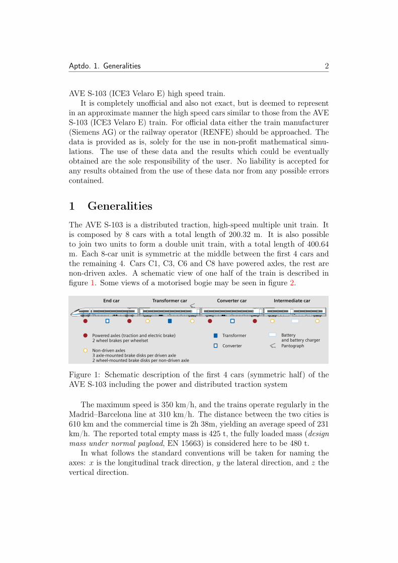
1 GeneralitiesThe AVE S-103 is a distributed traction, high-speed multiple unit train. Itis composed by 8 cars with a total length of 200.32 m. It is also possibleto join two units to form a double unit train, with a total length of 400.64m. Each 8-car unit is symmetric at the middle between the first 4 cars andthe remaining 4. Cars C1, C3, C6 and C8 have powered axles, the rest arenon-driven axles. A schematic view of one half of the train is described infigure 1. Some views of a motorised bogie may be seen in figure 2.
Trainset: The proven concept
The VELARO E is a multiple-unit trainsetin which the traction and all technicalmodules are distributed underflooracross the train. This means that the fulllength of the train is available to thepassengers, offering 20 % more roomthan conventional trains of the sametrain length. The ICE 3 of German Railand the VELARO E are the first Europeanhigh-speed trainsets.
The clear advantage:
Optimized performance characteristics.The trainset concept results in overalloperating advantages:
• Improved leverage of the adhesion coefficient during acceleration be-cause 50 % of the axles are driven
• Capability to run on sections with steeper gradients up to 40 ‰
ed into two trains for different final destinations.
Impressive traction
The VELARO E has four identical, inde-pendent traction units. This principleprovides clear advantages in continuousservice:
• If one traction unit fails, it can be dis-abled without affecting the remainingunits. This enables the train to safely reach its destination with 75 % of its maximum rated traction and brakingpower.
• Low-maintenance three-phase asyn-chronous motors with cage rotors en-sure high availability for productive service.
• To achieve the huge traction power, the transformer rating has beenincreased by 10 % over the ICE 3 ofDB AG.
• Due to the evenly distributed weight across the entire trainset, the load forthe individual wheelset is reduced. This goes easy on the track and reduc-es the maintenance requirements onthe running gear. The load per wheel-set is significantly lower than the in-ternational standard of 17 metric tons.
Additional benefits:
Ultra-smooth ride. The evenly distribut-ed weight also improves the runningcharacteristics and thus the travel com-fort.
• The train length of 200 m has been perfectly chosen in view of the re-quirements of the Technical Specifica-tion of Interoperability (TSI). It meansthat the train can run in double trac-tion – with a total length of 400 m. The positive effect: The VELARO E canrun with two coupled trainsets on a section of the track and then be divid-
Converter
Batteryand battery charger
TransformerPowered axles (traction and electric brake)2 wheel brakes per wheelset
Non-driven axles3 axle-mounted brake disks per driven axle2 wheel-mounted brake disks per non-driven axle
Pantograph
End car Transformer car Converter car Intermediate car
22
InterCity®, ICE International®, ICE®, ICE T®, ICE TD® and ICE-Sprinter® are registered trademarks of German Rail (DB AG).VELARO® is a registered trademark of Siemens AG.
[kN]
300
275
250
225
200
175
150
125
100
75
50
25
0
Tractive effort diagram
1%
2%2,5%
3%
Horizontal
P(wheel, F) = 8800 kW (100% traction)
P(wheel, F) = 6600 kW (75% traction)
P(wheel, F) = 4400 kW (50% traction)
P(wheel, F) = 2200 kW (25% traction)
Figure 1: Schematic description of the first 4 cars (symmetric half) of theAVE S-103 including the power and distributed traction system
The maximum speed is 350 km/h, and the trains operate regularly in theMadrid–Barcelona line at 310 km/h. The distance between the two cities is610 km and the commercial time is 2h 38m, yielding an average speed of 231km/h. The reported total empty mass is 425 t, the fully loaded mass (designmass under normal payload, EN 15663) is considered here to be 480 t.
In what follows the standard conventions will be taken for naming theaxes: x is the longitudinal track direction, y the lateral direction, and z thevertical direction.
Aptdo. 2. Geometry 3
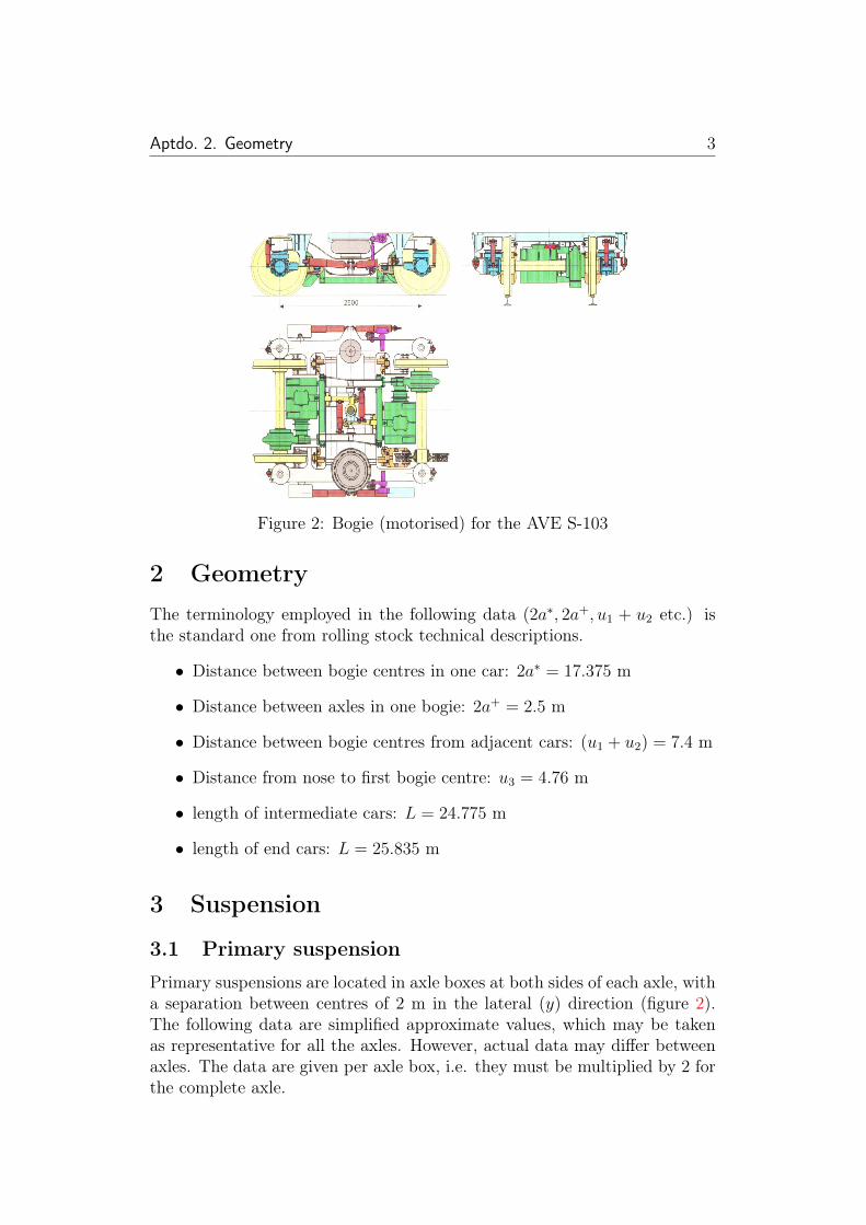
Figure 2: Bogie (motorised) for the AVE S-103
2 GeometryThe terminology employed in the following data (2a∗, 2a+, u1 + u2 etc.) isthe standard one from rolling stock technical descriptions.
• Distance between bogie centres in one car: 2a∗ = 17.375 m
• Distance between axles in one bogie: 2a+ = 2.5 m
• Distance between bogie centres from adjacent cars: (u1 + u2) = 7.4 m
• Distance from nose to first bogie centre: u3 = 4.76 m
• length of intermediate cars: L = 24.775 m
• length of end cars: L = 25.835 m
3 Suspension
3.1 Primary suspension
Primary suspensions are located in axle boxes at both sides of each axle, witha separation between centres of 2 m in the lateral (y) direction (figure 2).The following data are simplified approximate values, which may be takenas representative for all the axles. However, actual data may differ betweenaxles. The data are given per axle box, i.e. they must be multiplied by 2 forthe complete axle.
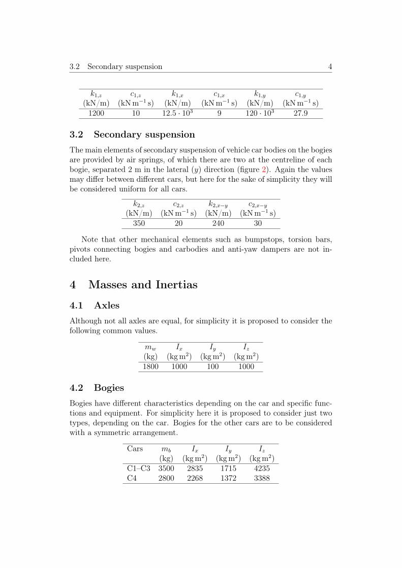
3.2 Secondary suspension 4
k1,z c1,z k1,x c1,x k1,y c1,y(kN/m) (kNm−1 s) (kN/m) (kNm−1 s) (kN/m) (kNm−1 s)1200 10 12.5 · 103 9 120 · 103 27.9
3.2 Secondary suspension
The main elements of secondary suspension of vehicle car bodies on the bogiesare provided by air springs, of which there are two at the centreline of eachbogie, separated 2 m in the lateral (y) direction (figure 2). Again the valuesmay differ between different cars, but here for the sake of simplicity they willbe considered uniform for all cars.
k2,z c2,z k2,x−y c2,x−y
(kN/m) (kNm−1 s) (kN/m) (kNm−1 s)350 20 240 30
Note that other mechanical elements such as bumpstops, torsion bars,pivots connecting bogies and carbodies and anti-yaw dampers are not in-cluded here.
4 Masses and Inertias
4.1 Axles
Although not all axles are equal, for simplicity it is proposed to consider thefollowing common values.
mw Ix Iy Iz(kg) (kgm2) (kgm2) (kgm2)1800 1000 100 1000
4.2 Bogies
Bogies have different characteristics depending on the car and specific func-tions and equipment. For simplicity here it is proposed to consider just twotypes, depending on the car. Bogies for the other cars are to be consideredwith a symmetric arrangement.
Cars mb Ix Iy Iz(kg) (kgm2) (kgm2) (kgm2)
C1–C3 3500 2835 1715 4235C4 2800 2268 1372 3388
4.3 Car bodies 5
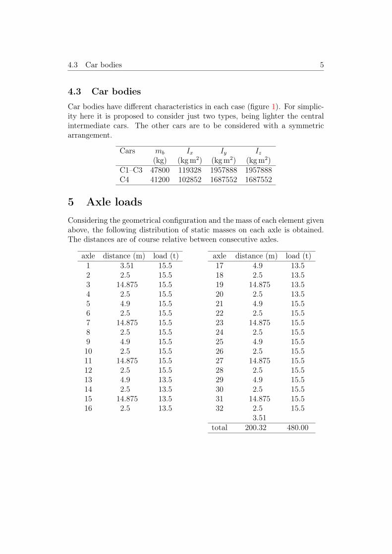
4.3 Car bodies
Car bodies have different characteristics in each case (figure 1). For simplic-ity here it is proposed to consider just two types, being lighter the centralintermediate cars. The other cars are to be considered with a symmetricarrangement.
Cars mb Ix Iy Iz(kg) (kgm2) (kgm2) (kgm2)
C1–C3 47800 119328 1957888 1957888C4 41200 102852 1687552 1687552
5 Axle loadsConsidering the geometrical configuration and the mass of each element givenabove, the following distribution of static masses on each axle is obtained.The distances are of course relative between consecutive axles.
axle distance (m) load (t)1 3.51 15.52 2.5 15.53 14.875 15.54 2.5 15.55 4.9 15.56 2.5 15.57 14.875 15.58 2.5 15.59 4.9 15.510 2.5 15.511 14.875 15.512 2.5 15.513 4.9 13.514 2.5 13.515 14.875 13.516 2.5 13.5
axle distance (m) load (t)17 4.9 13.518 2.5 13.519 14.875 13.520 2.5 13.521 4.9 15.522 2.5 15.523 14.875 15.524 2.5 15.525 4.9 15.526 2.5 15.527 14.875 15.528 2.5 15.529 4.9 15.530 2.5 15.531 14.875 15.532 2.5 15.5
3.51total 200.32 480.00