Embed Size (px)
Citation preview
Simplified Methodology for the Design and Optimization ofThermally Coupled Reactive Distillation SystemsFernando Israel Gomez-Castro,†,‡ Vicente Rico-Ramírez,*,† Juan Gabriel Segovia-Hernandez,‡
Salvador Hernandez-Castro,‡ Guillermo Gonzalez-Alatorre,† and Mahmoud M. El-Halwagi§
†Departamento de Ingenieria Quimica, Instituto Tecnologico de Celaya, Avenida Tecnologico y Garcia Cubas S/N, Celaya,Guanajuato, Mexico 38010‡Departamento de Ingenieria Quimica, Division de Ciencias Naturales y Exactas, Universidad de Guanajuato, Campus Guanajuato,Noria Alta S/N, Guanajuato, Guanajuato, Mexico 36050§The Artie McFerrin Department of Chemical Engineering, Texas A&M University, College Station, Texas, 77843-3122, UnitedStates
ABSTRACT: New intensified schemes have been recently proposed as an attempt to reduce energy requirements andequipment costs in reaction−separation processes. A design methodology for thermally coupled reactive distillation systems isproposed in this work. To design the columns, a method based on the Fenske−Underwood−Gilliland (FUG) equations isproposed and tested. The FUG equations, the mass and energy balances, and the phase equilibrium equations are used toformulate the model of the intensified systems. Such a model is then solved as a nonlinear programming problem; the objectivefunction is the minimization of the heat duty in the column. Biodiesel production through the esterification of oleic acid withsupercritical methanol is used as a case study. Results show the feasibility of obtaining designs with low energy requirements byusing the proposed methodology. Because of nonconvexities present in the formulation, the estimated interlinking flows for thereactive Petlyuk column might not correspond to a minimum for energy requirements. Nevertheless, the resulting designs notonly show low heat duties, with a difference of less than 2% from that minimum, but also have the capacity of achieving thedesired conversion and purities.
1. INTRODUCTION
Recent research efforts in the development of productionprocesses show an increasing concern for the reduction ofenvironmental impact due to human activity. In thoseapproaches, process intensification plays an important role.Process intensification is an area of chemical engineering whosemain goal is finding production alternatives with low energyrequirements, contaminant emissions, and cost. To achieve thatgoal, strategies including multitask equipment and processintegration have been proposed. The basic structure of most ofthe production processes consists of a vessel where a chemicalreaction takes place, consuming reactants and producing one ormore desired products and some undesired byproduct, followedby a separation train. The most widely used separation processis distillation, because there is a lot of knowledge about itsdesign and dynamic performance. Nevertheless, distillation hasan inherent low thermodynamic efficiency (or second lawefficiency, which represents the portion of the total energyentering the system which is actually used to perform theseparation) which derives into high energy requirements forthis operation. For distillation trains, attempts have been madeto enhance the separation efficiency and, as a consequence,reduce their energy requirements. Thermal coupling is amongthese approaches. The increase of the thermodynamic efficiencywhen thermal coupling is incorporated depends on the natureof the mixture,1 but in general, thermally coupled systems havehigher thermodynamic efficiencies than conventional distil-lation sequences.2 Thermal coupling implies the use of columnconfigurations to avoid remixing.3 For ternary mixtures, there
are three structures which have been widely studied: thePetlyuk column or fully thermally coupled sequence (FTCS,Figure 1a), the thermally coupled direct sequence (TCDS,Figure 1b), and the thermally coupled indirect sequence (TCIS,Figure 1c). It has been found that the thermally coupledsystems can reduce energy requirements from 30 to 50% whencompared with conventional sequences4−8 and may showbetter dynamic properties than conventional systems.9−12
Nevertheless, the physical implementation of the Petlyukcolumn is not convenient, because of the unfavorable pressureprofile required for its operation. Instead, a thermodynamicallyequivalent scheme, known as a dividing wall column (DWC),has been used at pilot and industrial scales.13,14 The DWCconsists of a single shell with a metallic plate which divides theshell and redistributes the internal flows of the column (Figure2), although nonwelded structures have been recentlyintroduced.13 Different control strategies for dividing wallcolumns have also been proposed.15,16
A system involving a distillation train and a reactor can beintensified by coupling the reaction and separation systems intoa reactive distillation column. Since both processes take place ina single shell, the equipment costs of reactive distillation arereduced. There are some additional advantages of using reactivedistillation: (i) it is possible to override the chemical
Received: February 18, 2011Revised: July 5, 2012Accepted: August 5, 2012Published: August 6, 2012
Article
pubs.acs.org/IECR
© 2012 American Chemical Society 11717 dx.doi.org/10.1021/ie201397a | Ind. Eng. Chem. Res. 2012, 51, 11717−11730

equilibrium limitations, (ii) selectivity can be enhanced whenmultiple chemical reactions occur, and (iii) the global energyrequirement is reduced when an exothermic reaction takesplace because the heat released by the reaction can be used tovaporize products and/or byproducts.17 Many products havebeen successfully produced in practice by reactive distillation,such as methyl acetate, fatty esters, methyl tert-butyl ether(MTBE), monoethylene glycol, and propylene oxide.18
Different design strategies have been proposed for reactivedistillation. Some of these approaches consist of estimatingcomposition changes for the simultaneous reaction anddistillation processes.19−26 Most of these graphical methodsare useful when dealing with mixtures of up to fourcomponents. On the other hand, mathematical programmingmethods have been proposed for the design and optimizationof reactive distillation columns, usually modeling the system asa mixed integer nonlinear programming (MINLP) prob-lem.27−31 The main advantage of such methods is that theyobtain the optimal (or close to optimal) solution, dependingmainly on the nature of the problem constraints. Even so, themathematical and computational efforts required to reach suchsolutions are significant, and the use of integer variables makesthis task even harder.27 Furthermore, a very accurate initialguess of the solution is usually required to enhance theconvergence of the system. When using nonderivative basedmethods, a good adjustment of the corresponding parameters is
also required. Other approaches include the use of orthogonalcollocation models to transform the mixed integer problem intoan equivalent problem with continuous variables.32−34
Following the success of reactive distillation, reactivethermally coupled systems have been recently studied as analternative for further reduction of fixed and variable costs inproduction processes. Barroso-Munoz et al.35 have proposedthree different configurations to produce ethyl acetate: areactive Petlyuk column, a reactive thermally coupleddistillation system with a side rectifier, and a reactive thermallycoupled distillation system with a side stripper. Mueller andKenig36 analyzed the reactive dividing wall column, which isthermodynamically equivalent to the reactive Petlyuk column,by using equilibrium and nonequilibrium stage models. Theimplementation of a reactive dividing wall column in a pilotplant has also been reported for the production of ethylacetate.37 Gomez-Castro et al.38,39 have shown the feasibility ofusing a reactive Petlyuk column and a reactive thermallycoupled direct sequence to produce biodiesel fuel withsupercritical methanol. Other approaches have been proposedfor using reactive distillation to produce fatty esters(biodiesel);40−43 nevertheless, the use of reactive distillationin high temperature and pressure processes to producebiodiesel has not been extensively considered.
2. THERMALLY COUPLED REACTIVE DISTILLATIONDESIGN
Most of the design approaches for thermally coupled reactivecolumns have been performed by a trial-and-error procedure,with the exception of the work of Kiss et al.,17 where graphicalmethods are applied. Nevertheless, the use of graphicalmethods for mixtures with more than four componentsbecomes difficult or infeasible. Thus, in this work a designmethodology for the reactive dividing wall column (RDWC)and the reactive thermally coupled direct sequence (RTCDS) isproposed. The proposed approach considers mass and energybalances and the use of the Fenske−Underwood−Gillilandequations to determine the number of separation stages. Twosolution strategies are considered. The first approachformulates the complete set of equations as a nonlinearprogramming (NLP) problem which intends to minimize theheat duty. The second strategy formulates only the mass andenergy balances of the various sections of the column as anNLP problem, and then uses the Fenske−Underwood−Gilliland equations to calculate the remaining design variables,i.e., the number of stages, reflux ratio, and location of theinterlinking streams.The proposed methodology can be applied to reactive
mixtures with any number of components, and it simplifiesconsiderably the mathematical effort for the solution of thesystem of equations. Furthermore, it provides an estimate of thenumber of both nonreactive and reactive stages to achieve boththe desired purities and the operating constraints. Results showthat both of the design strategies are able to obtain feasiblesystems with lower energy requirements than that of theconfiguration reported by Gomez-Castro et al.39 (assumed asinitial guess).
3. MODELING EQUATIONS
Our model formulation for the design of the reactive thermallycoupled systems includes mass balances, energy balances, phaseequilibrium relationships, and the design equations.
Figure 1. Thermally coupled distillation sequences: (a) Petlyukcolumn (FTCS); (b) thermally coupled direct sequence (TCDS); (c)thermally coupled indirect sequence (TCIS).
Figure 2. Simplified scheme of a dividing wall column.
Industrial & Engineering Chemistry Research Article
dx.doi.org/10.1021/ie201397a | Ind. Eng. Chem. Res. 2012, 51, 11717−1173011718

3.1. Mass Balances. Consider the reactive distillationcolumn shown in Figure 3, with two feeds and three products.
The column has a nonreactive section (section 1) and a reactivesection (section 2), and from the delimiting tray of those twosections, a side stream is withdrawn. In the reactive section, areversible chemical reaction, νAA + νBB ↔ νCC + νDD, occurs.A material balance for component i on the top of section kresults in
∑ ∑νν
= −⎛⎝⎜
⎞⎠⎟d z F f z Frec reci k
jd i j k j i j
i
r jj r j d i j k, , , , ,
rconv ,r , , ,
(1)
where di,k is the flow of component i at the top of the section k,recd,i,j,k is the value of the recovery factor for component i at thetop of section k from feed Fj, zj,i is the molar composition ofcomponent i in the feed stream Fj, νi is the stoichiometriccoefficient for component i, νrr is the stoichiometric coefficientfor a reference component r (which must be a reactant), andfconv is the expected conversion; the value of fconv can beassumed as the equilibrium conversion. In a similar way, a massbalance for component i at the bottom of section k results in
∑ ∑νν
= −⎛⎝⎜
⎞⎠⎟b z F f z Frec reci k
jb i j k j i j
i
r jj r j b i j k, , , , ,
rconv ,r , , ,
(2)
Consider now the reactive Petlyuk column (RPC) shown inFigure 4. Mass balance equations, eqs 1 and 2, may also beapplied to the main column of the RPC (sections 1 and 2), butthe feed flow rate Fj must be replaced by a total feed flow rateFjT, where
= +F F FV11T 1 (3)
= +F F FL22T 2 (4)
F1T is the pseudofeed stream to section 1 of the maincolumn, consisting of the fresh feed stream F1 and the vaporstream FV1 leaving the prefractionator; similarly, F2T is thepseudofeed stream to section 2 of the main column, consistingof F2 and FL2. Mass balance equations can also be obtained forthe prefractionator of the RPC (section 3) as follows (initialguesses for FL1 and FV2 are needed):
= +fFV1 (FL1 FV2)part (5)
= + −FL2 (FL1 FV2) FV1 (6)
where f part is the partition factor. The partition factor representsthe fraction of the total feed to the prefractionator which leavesthat section as a vapor flow; its value must be determined byenergetic considerations. The initial values for recd,i,j,k, f part, andfconv are in fact unknown, but they can be estimated prior to thedesign procedure through rigorous simulations.39 Nevertheless,since f part is a decision variable directly related to theinterlinking flows, its value is modified through theoptimization strategy, as will be described later.For the RTCDS, consider the system depicted in Figure 5.
The mass balance equations for the main column are also given
by eqs 1 and 2, but in the case of section 3, the total feedinvolves a pseudofeed stream composed by F1 and FL. Thematerial balance for the side rectifier is then given by eq 7:
= − DFL FV r (7)
3.2. Energy Balances. Global energy balances are used tocalculate the heat required to perform the separations. In thecase of the RPC, the total amount of heat entering the maincolumn (Qent,RPC) is given by eq 8.
= + + + +
+
Q h F h F h h Q
Q
FV1 FL2ent,RPC F 1 F 2 FV1 FL2 rxn
reb
1 2
(8)
In eq 8, h is the molar enthalpy of the stream, Qrxn is the heatof reaction, and Qreb is the thermal duty in the reboiler of themain column. The heat of reaction is calculated as follows:
νν
=⎛⎝⎜
⎞⎠⎟Q h f z Fi
i
rrrxn rxn,
rconv r ,F 11
(9)
where rr indicates the reference component for the reactionand hrxn,i is the molar enthalpy of reaction. Similarly, the totalamount of heat leaving the main column (Qout,RPC) is
Figure 3. Reactive distillation column with two feeds and threeproduct streams.
Figure 4. Section distribution for the mass balance in the RPC.
Figure 5. Section distribution for the mass balance in the RTCDS.
Industrial & Engineering Chemistry Research Article
dx.doi.org/10.1021/ie201397a | Ind. Eng. Chem. Res. 2012, 51, 11717−1173011719
= + + + +
+
Q h D h D h B h h
Q
FL1 FV2out,RPC D S B FL1 FV2
COND (10)
where QCOND is the heat removed by the condenser and can becalculated as
∑ λ==
Q V yi
i iCOND1
NC
Vd,(11)
In eq 11 λi is the enthalpy of vaporization for component i,yVd,i is the composition of component i in the vapor enteringthe condenser, and V is the flow rate for such a vapor stream.The reboiler duty is then calculated as
= − + + +
+
Q Q h F h F h h
Q
( FV1 FL2
)
reb out,RPC F 1 F 2 FV1 FL2
rxn
1 2
(12)
Similarly, for the RTCDS, the heat entering the main columnis computed as given by eq 13:
= + + + +Q h F h F h Q QFLent,RTCDS F 1 F 2 FL rxn reb1 2 (13)
The heat leaving the main column of the RTCDS is given by
= + + +Q h D h B h QFVout,RTCDS D B FV COND (14)
Thus, the amount of energy required in the reboiler of thecolumn is
= − + + +Q Q h F h F h Q( FL )reb out F 1 F 2 FL rxn1 2 (15)
3.3. Phase Equilibrium. Phase equilibrium calculations areneeded to perform mass and energy balances. The thermody-namic models used and the number of phases involved willdepend on the system under analysis. For instance, a phi−gamma (Φ−γ) formulation can be used for vapor−liquidequilibrium calculations (VLE), although it is quite common tofind three-phase mixtures (VLLE) in reactive distillationsystems.In the VLE case (which will be used later in our case study),
the equilibrium constant and the activity coefficients of theΦ−γ formulation are given by44
γ= =
ΦK
y
x
P
Pi
i
i i
ieq
sat
(16)
where the activity coefficient has been calculated by using theNRTL model equations. The interaction parameters can beestimated through experimental data or through the help of aprocess simulator.3.4. Design Equations. The use of the Fenske−Under-
wood−Gilliland (FUG) and the Kirkbride equations constitutesthe classical approach for the design of conventional distillationcolumns by shortcut methods. A modified version of thoseequations is used in this work for the design of the thermallycoupled reactive distillation systems; the modifications appliedare described in section 4.
4. DESIGN STRATEGYA modified version of the Underwood equations is used for thedesign of thermally coupled reactive distillation systems. Thissection provides the assumptions made in this work whenapplying the shortcut method based on the FUG and Kirkbrideequations.
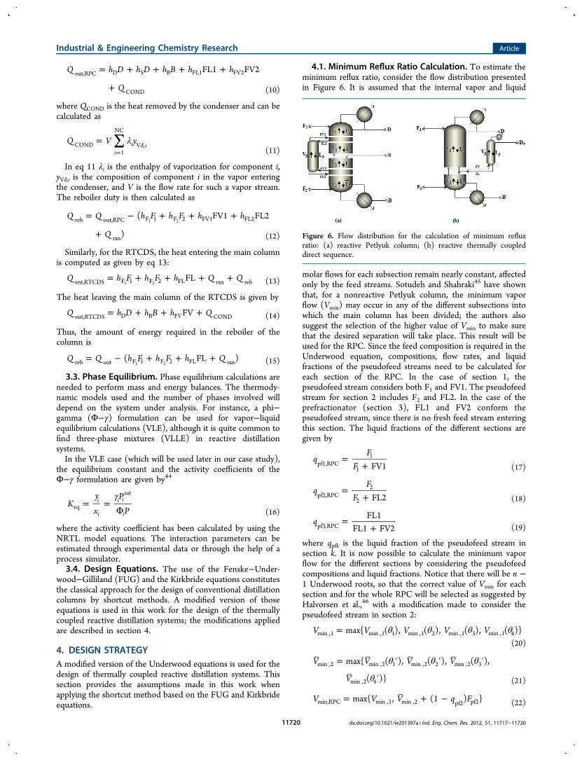
4.1. Minimum Reflux Ratio Calculation. To estimate theminimum reflux ratio, consider the flow distribution presentedin Figure 6. It is assumed that the internal vapor and liquid
molar flows for each subsection remain nearly constant, affectedonly by the feed streams. Sotudeh and Shahraki45 have shownthat, for a nonreactive Petlyuk column, the minimum vaporflow (Vmin) may occur in any of the different subsections intowhich the main column has been divided; the authors alsosuggest the selection of the higher value of Vmin to make surethat the desired separation will take place. This result will beused for the RPC. Since the feed composition is required in theUnderwood equation, compositions, flow rates, and liquidfractions of the pseudofeed streams need to be calculated foreach section of the RPC. In the case of section 1, thepseudofeed stream considers both F1 and FV1. The pseudofeedstream for section 2 includes F2 and FL2. In the case of theprefractionator (section 3), FL1 and FV2 conform thepseudofeed stream, since there is no fresh feed stream enteringthis section. The liquid fractions of the different sections aregiven by
=+
qF
F FV1pf1,RPC1
1 (17)
=+
qF
F FL2pf2,RPC2
2 (18)
=+
qFL1
FL1 FV2pf3,RPC (19)
where qpfk is the liquid fraction of the pseudofeed stream insection k. It is now possible to calculate the minimum vaporflow for the different sections by considering the pseudofeedcompositions and liquid fractions. Notice that there will be n −1 Underwood roots, so that the correct value of Vmin for eachsection and for the whole RPC will be selected as suggested byHalvorsen et al.,46 with a modification made to consider thepseudofeed stream in section 2:
θ θ θ θ=V V V V Vmax{ ( ), ( ), ( ), ( )}min ,1 min ,1 1 min ,1 2 min ,1 3 min ,1 4
(20)
θ θ θ
θ
= ′ ′ ′
′
V V V V
V
max{ ( ), ( ), ( ),
( )}
min ,2 min ,2 1 min ,2 2 min ,2 3
min ,2 4 (21)
= + −V V V q Fmax{ , (1 ) }min,RPC min ,1 min ,2 pf2 pf2 (22)
Figure 6. Flow distribution for the calculation of minimum refluxratio: (a) reactive Petlyuk column; (b) reactive thermally coupleddirect sequence.
Industrial & Engineering Chemistry Research Article
dx.doi.org/10.1021/ie201397a | Ind. Eng. Chem. Res. 2012, 51, 11717−1173011720

where θn and θn′ are the nth Underwood roots for section 1 andsection 2, respectively, Vmin,1(θn) is the minimum vapor flow insection 1 calculated with the Underwood root θn, Vmin,2(θn′) isthe minimum vapor flow in section 2 calculated with theUnderwood root θn′, Fpf2 is the molar flow rate of thepseudofeed stream in section 2, and Vmin,RPC is the minimumvapor flow for the reactive Petlyuk column.Similar assumptions have been made for the calculation of
Vmin in the case of the RTCDS. Section 1 has only one feedstream (F1), but a pseudofeed stream composed by F2 and FLhas been used in the case of section 2. The liquid fraction forthis pseudofeed stream is given by
=+
qF
FLFLpf2,RTCDS
2 (23)
The values for the minimum vapor flow in sections 1 and 2are given by eqs 20 and 21. For section 3 the resultingexpression is given by eq 24.
θ θ θ
θ
= ″ ″ ″
″
V V V V
V
max{ ( ), ( ), ( ),
( )}
min ,3 min ,3 1 min ,3 2 min ,3 3
min ,3 4 (24)
where θn″ is the nth value of the Underwood root in section 3of the RTCDS. Since there are two condensers in thatconfiguration, there will also be two values of Vmin, one for thecondenser of the main column and the other for the condenserof the side rectifier. Those values are estimated by using anapproach similar to that presented for the reactive Petlyukcolumn:
= + −V V V q Fmax{ , (1 ) }min,RTCDS(MC) min ,1 min ,2 pf2 pf2
(25)
=V Vmin,RTCDS(SR) min ,3 (26)
In eq 25, Vmin,RTCDS(MC) is the minimum vapor flow in the maincolumn of the RTCDS, and in eq 26, Vmin,RTCDS(SR) is theminimum vapor flow in the side rectifier of the RTCDS.4.2. Minimum and Actual Number of Stages. The
minimum number of stages for each of the three main sectionsof an RDC is calculated through the Fenske equation in a waysimilar to that in the nonreactive case, which is a significantassumption and the main source of error in this approach.From mass balances, the compositions of both the distillate andthe side stream are known. In the case of section 2 thecompositions of the side stream and of the bottom are alsoknown. For section 3 the required data are the vaporcomposition of the FV1 stream and the liquid composition ofFL2; such data may also be estimated from the mass balances inthe prefractionator. The relative volatilities can be evaluated asthe geometric average of the relative volatilities at the top andbottom of each section.In the case of the RTCDS, calculation of the minimum
number of stages for section 1 can be performed by using thecomposition at the top of the main column and thecomposition of the liquid in equilibrium with the vapor streamFV. For section 2, the compositions used are thosecorresponding to FV and to the bottom of the main column.Finally, for the side rectifier, distillate compositions of section 3and the liquid stream FL compositions are used.Once the minimum number of stages has been calculated,
the basic Gilliland equation (another source of error) is thenused to estimate the actual number of stages. Since the actual
reflux ratio is unknown, a factor “facrd” has been used tocalculate it through the expression RRPC = (facrd)Rmin,RPC. As aninitial guess, this factor has been considered equal to 1.3. Forthe RTCDS, calculation of the actual number of stages isperformed in a similar way, using the factors “facrdc” and“factdcsr” for the main column and the side rectifier,respectively.
4.3. Feed and Product Stages. The Kirkbride equation isused to estimate the feed stages (location of the interlinkingstreams). In order to design the reactive dividing walldistillation column (RDWC), interlinking streams FV1 andFL1 are enforced to be located on the same stage. The sameconstraint applies to FV2 and FL2. The stage distribution forthe RPC is shown in Figure 7a. The numbers of stages N2, N3,
N4, and N5 are computed by using the Kirkbride equation. Thenumber of stages on the prefractionator (N1) was calculated asthe sum of N3 and N4, since those are the stages in which thedividing wall must be installed.In the case of the RTCDS, since the only interlinking stage is
located on the boundary stages between sections 1 and 2, itslocation is implicitly determined by the Gilliland equation, asseen in Figure 7b. Thus, it is not necessary to use the Kirkbrideequation for this system.
5. SOLUTION APPROACHThe design and optimization of the reactive thermally coupledsystems is first posed as an NLP problem which intends tominimize the heat duty in the reboilers (external energyrequirements on the column). The solution of the problem wasobtained by using the CONOPT solver within GAMS. Clearly,the number of stages is an integer variable, but the solution issimplified through the FUG equations so it was assumed to bea continuous variable.Two solution strategies were used. In the first one (method
1), the complete set of equations was solved as an NLP byusing the design variables obtained in the literature39 as initialvalues. The second approach (method 2) considers thesimultaneous solution of only mass balances, energy balances,and equilibrium equations as an NLP problem, also aiming forthe minimum energy requirement; the results obtained werethen used to complete the calculations by applying the designequations with the optimal flows calculated through the NLP.The degrees of freedom in the DWC are the partition factor
in the prefractionator ( fpart), the factor to calculate the actualreflux ratio (facrd), and the interlinking flow rates FL1 and FV2
Figure 7. Stage distribution for the location of the interlinking flows:(a) reactive Petlyuk column; (b) reactive thermally coupled directsequence.
Industrial & Engineering Chemistry Research Article
dx.doi.org/10.1021/ie201397a | Ind. Eng. Chem. Res. 2012, 51, 11717−1173011721

for each component. In the case of the RTCDS, the degrees offreedom are the factor used to calculate the actual reflux ratiofor the main column (facrdc) and the factor used to calculatethe actual reflux ratio for the side rectifier (factdcsr).In general, the optimization problem is represented as
=
≥
Q
f x
g x
min
s.t. ( ) 0
( ) 0
reb
(27)
where Qreb is the thermal duty for a given system, and f(x) andg(x) are the model constraints. The constraints include themass and energy balances, the phase equilibrium equations, andthe design equations for method 1 and the mass and energybalances and the phase equilibrium equations for method 2.Table 1 provides the decision variables for both of the
thermally coupled systems under analysis. Most of the variablesshown in Table 1 have a direct impact on the thermalrequirements of the column. Notice that Table 1 also includessome factors used to calculate the main design variables: forinstance, the actual reflux ratio is determined by the minimumreflux ratio and the reflux factors (facrd, facrdc, and factdcsr);likewise, the composition, molar flow rate, and temperature ofthe interlinking flows are determined by the partition factor( f part).Notice that the optimization model does not consider either
the impact of investment costs in the optimal design or theability of the column to compensate for variations in the activityof the reactions. It has been reported that the use of reactivethermally coupled distillation systems does not necessarilyimply a significant increase in the investment costs.47
Furthermore, not all of the thermal coupling schemes havethe potential of being beneficial in terms of energy savings.48
We could expect the investment cost effect to be negligible withrespect to the utility costs (implicitly considered when
minimizing the thermal duty), but the effect of the activity ofthe reaction needs to be further investigated.Once the optimization strategy (and further sequential
calculations in method 2) provides an estimation of the columnconfigurations (parameters and design variables), a parametricsearch with respect to the main design variables is conducted byusing a process simulator, in order to test and to improve theperformance of the designs obtained by the shortcut method(in terms of energy requirements). The use of a processsimulator with rigorous thermodynamic models and hydraulicequations allows consideration of the effect of parameters suchas the reactive stage holdup, which is neglected by simplifieddesigns based on shortcut methods. Notice that, instead ofusing the reactive stage holdup (which implies a stage-by-stagecalculation), in our shortcut method we propose to incorporatethe reaction into the analysis through the estimation of theoverall conversion of the reactive system; such conversion isthen used in the mass balances. The estimation of the overallconversion will of course have to consider any informationregarding kinetics expressions which are consistent with thereactants involved. The complete design methodology in bothcases is depicted in Figure 8.
6. CASE STUDYThe reactive system studied involves biodiesel production bythe Saka−Dadan method.49 In particular, it consists of theesterification of oleic acid with supercritical methanol toproduce methyl oleate, as described by Gomez-Castro et al.38,39
The chemical reaction proceeds as indicated by eq 28:
+ ↔ +OLAC MeOH MeOL H O2 (28)
where OLAC stands for oleic acid, and MeOH, MeOL, andH2O represent methanol, methyl oleate, and water, respectively.Notice that 1 mol of methyl oleate is produced for each mole ofoleic acid used as reactant. When using eq 9, oleic acid (OLAC)is the reference component for the reaction and, therefore, hrxn,ihas been calculated for i = OLAC as 41 573.23 kJ/kmol.Esterification takes place at 7 MPa and 270 °C.50 The
reaction is reversible; however, the reverse reaction effects aresmall and a yield higher than 90% can be obtained.49 Theanalyzed system includes the four components involved in thereaction (OLAC, MeOH, MeOL, and H2O) as well as a smallamount of glycerol remaining from the two-phase separationprevious to the esterification step.39 It has been reported that,given the pressure and temperature conditions, the esterifica-tion reaction occurs in a single liquid phase;49,51 thus onlyvapor−liquid equilibrium (VLE) calculations are considered forthe phase equilibrium. The compositions for the two feedstreams are presented in Table 2. VLE calculations wereperformed through the Φ−γ model as described by eqs 16−19.Interaction parameters were obtained from the Aspen Oneprocess simulator and are given in Table 3. The parameter Cij isalways assumed as 0.3.The fatty acid rich stream contains waterand glycerol, whereas the methanol feed contains puremethanol. Both feed streams enter the system at 7 MPa and270 °C. The flow rate of the fatty acid feed stream is 267.58kmol/h; the methanol feed is 412.69 kmol/h.
7. RESULTS AND DISCUSSIONBefore the main results of our approach are discussed, thefollowing section provides a summary of the simplifyingassumptions made to complete the design procedure for ourcase study.
Table 1. Decision Variables for the Design of ThermallyCoupled Systems
RDWC
compositions of the interlinking streamstotal molar flow of the interlinking streamstemperature of the interlinking streamsfactor facrd for the calculation of actual reflux ratiopartition factor f part (fraction of feed going to the prefractionator)actual reflux ratio for the main columnnumber of stages in the prefractionatornumber of stages for the nonreactive section in the main columnnumber of stages for the reactive section in the main column
RTCDS
compositions of the interlinking streamstotal molar flow of the interlinking streamstemperature of the interlinking streamsfactor facrdc for the calculation of actual reflux ratioactual reflux ratio for the main columnfactor factdcsr for the calculation of actual reflux ratioactual reflux ratio for the side rectifiernumber of stages for the nonreactive section in the main columnnumber of stages for the reactive section in the main columnnumber of stages in the side rectifier
Industrial & Engineering Chemistry Research Article
dx.doi.org/10.1021/ie201397a | Ind. Eng. Chem. Res. 2012, 51, 11717−1173011722

7.1. Summary of Simplifying Assumptions. Thefollowing is a list of the main assumptions made to designthe thermally coupled reactive configurations applied to thecase study:
1. The esterification reaction occurs in a single liquidphase.49,51
2. Vapor−liquid equilibrium can be represented using aΦ−γ formulation.
3. The location of the methanol feed stream and the oleicacid feed stream is fixed at the bottom and top of themain column, respectively.
4. The pressure remains almost constant at 7 MPa acrossthe main columns of the thermally coupled reactiveconfigurations.
5. Sections with two feed streams are assumed as having asingle pseudostream with the purpose of performingcalculations for minimum reflux and minimum numberof stages.
6. The side stream on the main column of the RDWC islocated on the boundary region between the nonreactivesection and the reactive section.
7. The interlinking stream on the main column of theRTCDS is located on the boundary region between thenonreactive section and the reactive section.
8. All of the variables involved in the optimization strategyare assumed to be continuous.
Further, notice that the presence of nonideal conditions(such as the existence of azeotropes) complicates any approachto the design of reactive separation systems. We believe,however, that the boundaries imposed for those nonidealconditions can be considered a priori on a case-by-case basis, so
Figure 8. Design methodology: (a) method 1; (b) method 2.
Table 2. Compositions of the Feed Streams (mol %)
component fatty acid feed methanol feed
MeOH 0.0000 1.0000H2O 0.4825 0.0000GLI 0.0035 0.0000OLAC 0.5139 0.0000MeOL 0.0000 0.0000
Table 3. Binary Interaction Parameters for the NRTL Equation
Aij
component MeOH H2O GLI MeOL OLAC
MeOH 0.0000 −2.6260 0.0000 0.0000 0.0000H2O 4.8241 0.0000 −1.0937 0.0000 0.0000GLI 0.0000 −0.7026 0.0000 0.0000 0.0000MeOL 0.0000 0.0000 0.0000 0.0000 0.0000OLAC 0.0000 0.0000 0.0000 0.0000 0.0000
Bij
component MeOH H2O GLI MeOL OLAC
MeOH 0.0000 828.3871 559.8946 997.3854 662.8329H2O −1329.5435 0.0000 226.6530 5916.0432 4978.8569GLI −221.4105 157.4594 0.0000 2684.4196 1804.7939MeOL 66.9798 930.1429 2255.1778 0.0000 255.5463OLAC −182.3177 537.2737 1100.3134 −132.5211 0.0000
Industrial & Engineering Chemistry Research Article
dx.doi.org/10.1021/ie201397a | Ind. Eng. Chem. Res. 2012, 51, 11717−1173011723

the existence of azeotropes can be predicted before using anydesign methodology through rigorous simulation or by reactiveresidual curves. For the case study under consideration, thereare no physical or reactive azeotropes reported. In our work,rigorous simulations were performed before the optimizationprocedure. If an azeotrope is predicted or is known to exist insome other system, its presence will affect the maximumpossible recovery, which is a parameter involved in the designstrategy that we proposed here.7.2. Results. The column configurations obtained from
both of the solution methods are presented in Table 4 for the
RDWC. Method 1 is the simultaneous solution of the wholesystem of equations, whereas method 2 corresponds to thesolution of the mass and energy balances and the posteriordesign of the column. In Table 4, Npre is the number of stageson the prefractionator, NMC,calc is the number of stages on themain column as calculated, and NMC,total is the total number ofstages in the main column, including the condenser and thereboiler. For the calculation of the feed stage in the maincolumn of the RDWC, the fatty acid feed F1 has been located instage 2 and the methanol feed is located at the bottom of thecolumn. Those decisions were made in our case study becauseany other configuration of those two feed streams causes failureon the mass balances and drying of the stages on the columnsfor both systems.38,39
Those configurations were tested by simulations on AspenOne by assuming 99 mol % purity for water, 90 mass % purityfor methyl oleate, and 91.33 mol % purity for methanol. Theenergy requirement provided in Table 4 corresponds to theresults of the simulations.After the design variables were estimated through the
proposed approach, a sensitivity analysis was performed withrespect to the main design variables to determine if the designsobtained are the systems with the lowest heat duty; otherwise,the analysis may suggest some modifications to the values ofthe design variables. In the analysis, a residence time of 0.3 h forall the reactive stages has been considered, as proposed in aprevious work.38 Changes in the heat duty when the location ofthe side stream is modified are shown in Figure 9. When theside stream is extracted from the reactive section (instead of theboundary zone between the nonreactive and reactive zones),the heat duty in the column is considerably reduced, passing
through a minimum and then being increased as the sidestream stage gets close to the bottom of the column. Moreover,Figure 10 provides an analysis of the effect of Qreb when the
numbers of reactive and nonreactive stages are increased.Incorporating one additional reactive stage to the initialconfiguration reduces heat duty, but when more reactive stagesare added, no convergence is achieved for the purities specified;this problem is expected to occur, since shortcut models moreeasily satisfy product specifications than rigorous models. Whenmore nonreactive stages are used, a decrease in the thermalduty is observed, but that reduction is not as significant as theone observed when the number of reactive stages is increased.Optimization curves for the interlinking flows are presented inFigure 11a for the design obtained by method 1 and in Figure11b for the design obtained by method 2. The initial valuescorrespond to the interlinking flow rates as calculated by theoptimization methodology. When the interlinking flow rate ischanged, a decrease in heat duty is achieved, but this reductionis minimal (less than 1% relative to the initial value). Thus, theinitial values for the interlinking flow rates are used for the finalconfigurations. After studying the results from the designstrategy and the sensitivity analysis, the final values for thedesign variables for the RDWC were selected and are providedin Table 5. Simulations for a reactive distillation column(RDC1) with a side stream were performed for comparisonpurposes; the RDC1 has the same number of stages as the maincolumn of the RDWC. The results for the RDC1 are alsoincluded in Table 5. The design of the RDWC obtained bymethod 2 (RDWC2) has the lowest heat duty among the threesystems, and even the RDC1 has lower energy requirementsthan the RDWC designed by method 1 (RDWC1). Never-
Table 4. Designs Obtained from the Two Solution Methods,RDWC
method 1 method 2
N1 5 4N2 3 3N3 3 3N4 2 1N5 1 2Npre 5 4NMC,calc 9 9NMC,total 11 11Nreac 8−10 8−10interlinking stages 4, 9 4, 8side stream stage 7 7Rcol 1.027 1.214FL1 (kmol/h) 14.982 6.214FV2 (kmol/h) 62.813 76.185Qreb,sim (kJ/h) 53 083 486.4 46 344 109.2
Figure 9. Variation of energy requirements with respect to changes inthe side stream withdrawal stage (RDWC).
Figure 10. Variation of energy requirements with respect to changes inthe numbers of reactive and nonreactive stages (RDWC).
Industrial & Engineering Chemistry Research Article
dx.doi.org/10.1021/ie201397a | Ind. Eng. Chem. Res. 2012, 51, 11717−1173011724

theless, both of the reactive dividing wall columns have thesame number of stages; notice that the difference between themis only the definition of the interlinking stages. Therefore,according to these results, the design problem of a reactivethermally coupled system seems to be very sensitive to thechanges in any of the design variables (number of reactivestages, location of both the side stream and the interlinkingstages) and care must be taken when solving this kind ofproblem.The values for design variables calculated for the RTCDS are
presented in Table 6. The number of stages needed for the siderectifier is equal to 1, which means that the separation is easy.Given that result, for simulation purposes, an alternative system
including a main column with a flash vaporizer attached insteadof the side rectifier was tested. The system is presented inFigure 12. Purities are specified as 91.29 mass % for methyl
oleate, 99 mol % for water, and 89.9 mol % for methanol. Forthis system, high energy requirements can be observed in Table6, especially for the design obtained by method 2 (RTCDS2).Then, a sensitivity analysis with respect to the main designvariables was also performed, trying to improve the designsobtained through our approach. Figure 13 shows the changes inenergy requirements against changes in the location of theinterlinking flow. When the interlinking streams are locatednear the bottom of the column, the heat duty is reduced. Figure14 presents the results when the numbers of reactive andnonreactive stages are modified; energy requirements areconsiderably reduced if one reactive stage is added to the
Figure 11. Optimization curves for interlinking flows in the RDWC:(a) design obtained by method 1; (b) design obtained by method 2.
Table 5. Final Designs Obtained from the Two Initial Optimal Solutions, RDWC
RDWC1 RDWC2
prefractionator main column prefractionator main column RDC1
N 5 12 4 12 12Rcol 0.6564 1.5640 0.1787 1.3032 1.5278Qcond (kJ/h) 0 29 600 659.0 0 26 758 629.0 29 206 313Qreb (kJ/h) 0 27 468 663.3 0 24 845 934.9 27 099 117.7side stream stage − 10 − 10 10reactive stages − 8−11 − 8−11 8−11conversion (%) − 99.95 − 99.97 99.97interlinking stages 1, 5 5, 10 1, 4 5, 9 −FV2 (kmol/h) − 62.813 − 76.185 −FL1 (kmol/h) − 14.982 − 6.214 −Td (K) 506.94 332.04 506.29 332.03 332.04Tb (K) 510.16 559.94 507.32 561.83 559.92Pd (bar) 69.65 69.65 69.65 69.65 69.65Pb (bar) 69.65 70.34 69.65 70.34 70.34
Table 6. Designs Obtained from the Two Solution Methods,RTCDS
method 1 method 2
N1 7 7N2 3 2N3 1 1NMC,calc 10 9NMC,total 12 11Nsr 1 1Nreac 9−11 9−10interlinking stages 8 8Rcol 1.421 0.01FV (kmol/h) 181.788 181.009Qreb,sim (kJ/h) 42 626 674.5 75 930 163.3
Figure 12. System alternative to RTCDS.
Industrial & Engineering Chemistry Research Article
dx.doi.org/10.1021/ie201397a | Ind. Eng. Chem. Res. 2012, 51, 11717−1173011725

RTCDS2. No more stages could be added due to convergenceproblems. Furthermore, an increment in Nreac was not possiblein the case of the RTCDS1 (a single point appears for reactivestages in the design obtained by using method 1). Notice thatenergy requirements of both of the RTCDS systems becomealmost the same after one additional reactive stage has beenincorporated to the RTCDS2 and the RTCDS1 remainsunchanged. In addition, a slight reduction in energy require-ments is observed in both cases when the number ofnonreactive stages is increased. Changes in the interlinkingstream flow rate are feasible, but they were avoided to maintainthe quality of the stream leaving the side vaporizer withinspecifications. Thus, the FV flow rate was fixed at the valueobtained by the optimization method. The final designs for theRTCDS are presented in Table 7. In this case only the data forthe main column are presented. The side vaporizer operates at7 MPa and 229 °C, with a vapor fraction of approximately 0.96.Again, a reactive distillation column was used to contrast theperformance of the thermally coupled designs. Here, the RDC(RDC2) was designed considering the total number of stages ofthe thermally coupled sequence, i.e., the number of stages onthe main column plus an additional stage for the side vaporizer.Both of the modified designs for the RTCDS are basically thesame, and their energy requirements are quite similar.Furthermore, the equivalent reactive distillation schemepresents considerably higher energy requirements whencompared to the RTCDS configurations.For the purpose of comparison, Table 8 presents the results
obtained for the design of the RDWC using both the shortcutmethod and the rigorous simulation; similarly, a comparison forthe RTCDS is shown in Table 9. The optimal designs obtainedfor the RDWC by the shortcut method and those modified by
the rigorous simulation are quite similar, and the maindifference corresponds to the location of the side stream.Nevertheless, small changes in that variable allow reductions ofabout 48% (method 1) and 46% (method 2) in the energydemand. For the RTCDS, small variations in the location of theinterlinking stage also allow reductions of 38% (method 1) and65% (method 2) in the reboiler duty.The global mass and energy balances for the initial designs
and the optimized designs with the lowest energy requirementsare shown in Table 10; the index “i” represents the initial,nonoptimized designs. Since the different systems are designedto accomplish purity constraints, the material balances do not
Figure 13. Variation of energy requirements with respect to changes inthe interlinking stream withdrawal stage (RTCDS).
Figure 14. Variation of energy requirements with respect to changes inthe number of reactive and nonreactive stages (RTCDS).
Table 7. Final Designs Obtained from the Two InitialOptimal Solutions, RTCDS
RTCDS1, maincolumn
RTCDS2, maincolumn RDC2
N 12 12 13Rcol 1.1898 1.2910 2.6220Qcond (kJ/h) 24 541 002.0 24 687 013.2 40 822
693.0Qreb (kJ/h) 26 227 225.0 26 762 709.2 38 934
856.3side stream stage − − 10reactive stages 9−11 9−11 10−12conversion (%) 99.86 99.88 99.06interlinkingstages
10 10 −
FV (kmol/h) 181.788 181.009 −Td (K) 332.02 332.04 332.04Tb (K) 568.10 568.26 568.32Pd (bar) 69.65 69.65 69.65Pb (bar) 70.34 70.34 70.34
Table 8. Comparison between the Obtained Designs for theRDWC
RDWC1 RDWC2
shortcut rigorous shortcut rigorous
Npre 5 5 4 4NMC 11 12 9 12Nreac 3 4 3 4interlinking stages 4, 9 5, 10 4, 8 5, 9side stream stage 7 10 7 10Rcol 1.027 1.564 1.214 1.303FL1 (kmol/h) 14.982 14.982 6.214 6.214FV2 (kmol/h) 62.813 62.813 76.185 76.185Qreb (kJ/h) 53 083
486.427 468663.3
46 344109.2
24 845934.9
Table 9. Comparison between the Obtained Designs for theRTCDS
RTCDS1 RTCDS2
shortcut rigorous shortcut rigorous
NMC 12 12 11 12Nsr 1 1 1 1Nreac 3 3 2 3interlinkingstages
8 10 8 10
Rcol 1.421 1.1898 0.01 1.291FV (kmol/h) 181.788 181.788 181.009 181.009Qreb (kJ/h) 42 626
674.526 227225.0
75 930163.3
26 762709.2
Industrial & Engineering Chemistry Research Article
dx.doi.org/10.1021/ie201397a | Ind. Eng. Chem. Res. 2012, 51, 11717−1173011726

differ considerably for the product streams, and the differencesin the energy requirements for the analyzed systems dependmainly on the energetic contents of the interlinking streams. Hrepresents the molar enthalpy of each of the correspondingstreams listed in Table 10. Finally, a comparison among theenergy requirements for the initial designs and the optimizeddesigns is presented in Table 11. The reference for the
calculation of the percentage of reduction is the initial designfor a reactive distillation column.39 It is clear that all of theoptimized systems (RDWC1, RDWC2, RTCDS1, andRTCDS2) present considerably lower energy requirementsthan the initial systems. The case of the RDC2 system isinteresting, since its heat duty is even higher than that of theinitial system; this result may indicate that designing an RDCbased on the RTCDS system is not appropriate, perhaps due tothe difference in the side stream phase.
According to our results, the design and optimizationmethodology allows obtaining designs for thermally coupledreactive distillation systems with lower energy demands thanthose of the initial designs obtained by pure parametric analysis.It is clear that the use of the FUG equations to design thecolumns is questionable because such equations were originallydeveloped for conventional distillation, whereas in reactivedistillation different phenomena such as mixing and diffusioncontrolled reactions may modify the performance of theprocess. Nevertheless, since the proposed method onlyconsiders global material and energy balances, it could beexpected that such phenomena have their main effect on theinternal profiles, not on the external data required for thecalculations. Furthermore, the reaction takes place in a singleliquid phase with low mass transfer resistance and high reactionrate, so the mentioned effects can be expected to be lower. Ofcourse, further analysis is needed to determine if suchconsiderations are acceptable for reactions limited byequilibrium or by mass transfer. For the case study presentedhere, the FUG equations have been shown to be useful todetermine an appropriate number of stages for the nonreactivesections but, for the reactive sections, the number of stages islower than the one required. Nevertheless, very small changes,such as increasing the number of stages by just one, allowobtaining the desired purities and conversions. Thus, the FUGmethod may underestimate the design of the reactive section,but only slight modifications were needed to achieve theexpected performance.On the other hand, it has been noticed that the energy
demand for the different analyzed systems has beenconsiderably reduced when manipulating the location of theside stream. This occurs because it has been assumed in thedesign methodology that the side stream is located on theboundary region between the reactive and nonreactive sections;thus the NLP solution presents designs which fulfill such aconstraint. Nevertheless, according to the sensitivity analysis,the side stream must be located inside the reactive section ofthe column to achieve low thermal duty.As expected, for the RTCDS, the results show that method 1
allows obtaining better designs in terms of thermal duty thanmethod 2. However, for the RDWC, the results of method 2are better than those of method 1. In general, simultaneoussolution (method 1) should result in better designs. Never-theless, since the number of stages in method 1 is considered tobe a continuous variable in the optimization strategy, and giventhe high sensitivity of the system to small changes in thestructure, we speculate that the NLP solution for the designequations predicts an inappropriate location for the interlinkingstages in the RDWC; this may be due to the fact that shortcutequations lack significant gradient information that could leadthe design to the actual optimal point. As shown in Table 4,even a small change in the location of the interlinking stagesmay rise to higher energy requirements. Notice that this effectdoes not impact the results for the RTCDS, where theinterlinking stage has been fixed at the boundary regionbetween the reactive and nonreactive sections.
8. CONCLUSIONSA simplified design method for thermally coupled reactivedistillation systems has been presented. The design is based onthe FUG equations; the use of the FUG equations to design thecolumns is of course questionable because such equations wereoriginally developed for conventional distillation. The potential
Table 10. Mass and Energy Balances for the Initial andOptimal Cases
RDCi RD1 RPCi RDWC2 RTCDSi RTCDS1
F1 (kmol/h) 267.63 267.63 267.63 268.76 267.63 267.63
F2 (kmol/h) 412.77 412.77 412.77 412.77 412.77 412.77
D (kmol/h) 265.81 266.65 265.81 268.39 250.15 251.92
S/Dr (kmol/h)
158.76 159.32 158.76 161.48 174.63 174.97
B (kmol/h) 255.83 254.43 255.83 251.65 255.62 253.51
FV1/FV(kmol/h)
− − 20.02 64.98 181.44 181.79
FL1/FL(kmol/h)
− − 31.75 6.21 6.80 6.82
FV2 (kmol/h)
− − 31.75 76.19 − −
FL2 (kmol/h)
− − 43.48 15.03 − −
H − F1 (kJ/kmol)
−472670
−472670
−472670
−472260
−472670
−472670
H − F2 (kJ/kmol)
−193750
−193750
−193750
−193750
−193750
−193750
H − D (kJ/kmol)
−286910
−287900
−287560
−287850
−287920
−287930
H − S/Dr(kJ/kmol)
−239140
−234860
−236420
−235910
−223030
−203430
H − B (kJ/kmol)
−370930
−372370
−371090
−371380
−381280
−381980
H − FV1/FV(kJ/kmol)
− − −217380
−201690
−204230
−203680
H − FL1/FL(kJ/kmol)
− − −298430
−325850
−246670
−236180
H − FV2(kJ/kmol)
− − −207330
−204270
− −
H − FL2 (kJ/kmol)
− − −269220
−257270
− −
Table 11. Comparison of Energy Requirements for theInitial and Optimized Designs
design Qreb (kJ/h) reduction in energy requirements (%)
RDCi 35 053 076.2 0RPCi 31 680 293.7 9.62RTCDSi 27 745 638.2 20.85RDC1 27 099 117.7 22.69RDWC1 27 468 663.3 21.64RDWC2 24 845 934.9 31.84RDC2 38 934 856.3 11.07RTCDS1 26 227 225.0 25.18RTCDS2 26 762 709.2 23.65
Industrial & Engineering Chemistry Research Article
dx.doi.org/10.1021/ie201397a | Ind. Eng. Chem. Res. 2012, 51, 11717−1173011727

effect of phenomena such as mixing and diffusion controlledreactions is being neglected. However, for the case studypresented here, the FUG equations have shown to be useful todetermine an appropriate number of stages for the nonreactivesections and, for the reactive sections, only slight modificationswere needed to achieve the expected performance.The optimization strategy aims to minimize energy require-
ments by adjusting interlinking streams and the reflux ratios.Two solution methods have been proposed. One of the maincomplexities found when solving the complete system ofequations in method 1 occurs in the calculation of theUnderwood roots. On the other hand, different designs areobtained by both solution methods, which is natural becausemethod 1 is a simultaneous approach and method 2 is asequential approach. The designs obtained by both of theproposed methods have been studied through a sensitivityanalysis, aiming to improve the performance of theconfigurations and correct the values of the design variables(if needed).It has been found that, for the RDWC, high energy
requirements are obtained when the side stream is assumedto be located at the boundary region between the nonreactivezone and the reactive zone. Thus, the side stream must belocated in the reactive zone. The same occurs for theinterlinking flow on the RTCDS.As mentioned above, the number of reactive stages calculated
by the FUG equations results slightly lower than the requirednumber to obtain high conversions with low heat duty.However, only one additional reactive stage was necessary in allof the cases to achieve low thermal duty for the reboiler. In thecase of the interlinking flows on the RDWC, changes in energyrequirements, when the flow rates of FL1 and FV2 aremodified, are not significant. The final designs obtained doshow a significant reduction in energy requirements for bothsystems, RDWC and RTCDS, when compared to the initialdesigns.Thus, the proposed methodology allows obtaining proper
designs for the intensified systems under analysis, achieving thedesired purities and conversions with potential low heat duty.The method has been tested with a reaction occurring at a highreaction rate; further analysis is required for reactions limitedby chemical equilibrium. Furthermore, since the reaction underanalysis occurs at high temperature and pressure, additionalanalysis is also required to determine if such a system can besuccessfully operated in practice.
■ AUTHOR INFORMATIONCorresponding Author*E-mail: [email protected]. Tel.: (+52) 461 611 7575, ext156.NotesThe authors declare no competing financial interest.
■ ACKNOWLEDGMENTSThe authors acknowledge the financial support provided byCONACyT, PROMEP, and DGEST (Mexico).
■ NOMENCLATUREdi,k [kmol/h] = molar flow rate of component i at the top ofsection kbi,k [kmol/h] = molar flow rate of component i at the bottomof section k
D [kmol/h] = total molar flow rate of the distillate of themain columnS [kmol/h] = total molar flow rate of the liquid side streamof the main columnB [kmol/h] = total molar flow rate of the bottom of the maincolumnDr [kmol/h] = total molar flow rate of the distillate of theside rectifier in a reactive thermally coupled direct sequencefconv = molar global conversionf part = partition factorFj [kmol/h] = molar flow rate of feed stream jFkT [kmol/h] = molar flow rate of pseudofeed stream tosection kh [kJ/kmol] = molar enthalpy of the streamhrxn,i [kJ/kmol] = molar enthalpy of the reaction, referred tocomponent iKeq = vapor−liquid equilibrium constantPi
sat [Pa] = vapor pressure for component iP [Pa] = total pressure on the systemqpfk = liquid fraction for the pseudofeed stream to section kQCOND [kJ/h] = thermal energy released in the condenserQent [kJ/h] = total amount of heat entering the systemQout [kJ/h] = total amount of heat leaving the systemQreb [kJ/h] = thermal duty in the reboilerQrxn [kJ/h] = heat of reactionrecd,i, j,k = recovery of component i from feed stream j at thetop of section krecb,i, j,k = recovery of component i from feed stream j at thebottom of section kV [kmol/h] = molar flow rate of the vapor entering thecondenserVmin [kmol/h] = minimum vapor flowxi = molar composition of component i in the liquid phaseyi = molar composition of component i in the vapor phaseyVd,i = molar composition of component i in the vaporentering the condenserzj,i = molar composition of component i in feed stream j
Greek SymbolsΦi = corrected fugacity coefficientγi = activity coefficient for component iλi [kJ/kmol] = enthalpy of vaporization for component iνi = stoichiometric coefficient for component iνrr = stoichiometric coefficient for reference component r inthe reactionθn = Underwood root for section 1θn′ = Underwood root for section 2θn″ = Underwood root for section 3
■ REFERENCES(1) Agrawal, R.; Fidkowski, Z. T. Are Thermally Coupled DistillationColumns Always More Efficient for Ternary Distillations? Ind. Eng.Chem. Res. 1998, 37, 3444.(2) Flores, O. A.; Cardenas, J. C.; Hernandez, S.; Rico-Ramírez, V.Thermodynamic Analysis of Thermally Coupled Distillation Sequen-ces. Ind. Eng. Chem. Res. 2003, 42, 5940.(3) Triantafyllou, C; Smith, R. The Design and Optimization of FullyThermally Coupled Distillation Columns. Trans. Inst. Chem. Eng.1992, 70A, 118.(4) Petlyuk, F. B.; Platonov, V. M.; Slavinskii, D. M. Thermodynami-cally Optimal Method for Separating Multicomponent Mixtures. Int.Chem. Eng. 1965, 5 (3), 555.(5) Stupin, W. J.; Lockhart, F. J. Thermally Coupled DistillationACase History. Chem. Eng. Prog. 1972, 68 (10), 71.
Industrial & Engineering Chemistry Research Article
dx.doi.org/10.1021/ie201397a | Ind. Eng. Chem. Res. 2012, 51, 11717−1173011728

(6) Tedder, D. W.; Rudd, D. F. Parametric Studies in IndustrialDistillation: Part I. Design Comparisons. AIChE J. 1978, 24, 303.(7) Glinos, K.; Malone, F. Optimality Regions for Complex ColumnAlternatives in Distillation Systems. Chem. Eng. Res. Des. 1988, 66, 229.(8) Amminudin, K. A.; Smith, R.; Thong, D. Y.-C.; Towler, G. P.Design and Optimization of Fully Thermally Coupled DistillationColumns. Part 1: Preliminary Design and Optimization Methodology.Trans. Inst. Chem. Eng. 2001, 79 (Part A), 701.(9) Hernandez, S.; Jimenez, A. Controllability Analysis of ThermallyCoupled Distillation Systems. Ind. Eng. Chem. Res. 1999, 38, 3957.(10) Jimenez, A.; Hernandez, S.; Montoy, F. A.; Zavala-García, M.Analysis of Control Properties of Conventional and NonconventionalDistillation Sequences. Ind. Eng. Chem. Res. 2001, 40, 3757.(11) Segovia-Hernandez, J. G.; Hernandez, S.; Jimenez, A. ControlBehaviour of Thermally Coupled Distillation Sequences. Tran. Inst.Chem. Eng. 2002, 80, 783.(12) Segovia-Hernandez, J. G.; Hernandez, S.; Rico-Ramirez, V.;Jimenez, A. A Comparison of the Feedback Control BehaviourBetween Thermally Coupled and Conventional Distillation Schemes.Comput. Chem. Eng. 2004, 28, 811.(13) Dejanovic, I.; Matijasevic, Lj.; Olujic, Z. Dividing WallColumnA Breakthrough Towards Sustainable Distilling. Chem.Eng. Process. 2010, 49, 559.(14) Olujic, Z.; Jodecke, M.; Shilkin, A.; Schuch, G.; Kaibel, B.Equipment improvement trends in distillation. Chem. Eng. Process.2009, 48 (6), 1089.(15) van Diggelen, R. C.; Kiss, A. A.; Heemink, A. W. Comparison ofControl Strategies for Dividing-Wall Columns. Ind. Eng. Chem. Res.2010, 49, 288.(16) Kiss, A. A.; Bildea, C. S. A Control Perspective on ProcessIntensification in Dividing-Wall Columns. Chem. Eng. Process. 2011,50, 281.(17) Kiss, A. A.; Pragt, J. J.; Van Strien, C. J. G. Reactive Dividing-Wall ColumnsHow to Get More with Less Resources? Chem. Eng.Commun. 2009, 196, 1366.(18) Taylor, R.; Krishna, R. Modelling Reactive Distillation. Chem.Eng. Sci. 2000, 55, 5183.(19) Buzad, G.; Doherty, M. F. Design of Three-ComponentKinetically Controlled Reactive Distillation Columns Using Fixed-Points Methods. Chem. Eng. Sci. 1994, 49 (12), 1947.(20) Buzad, G.; Doherty, M. F. New Tools for the Design ofKinetically Controlled Reactive Distillation Columns for TernaryMixtures. Comput. Chem. Eng. 1995, 19 (4), 395.(21) Giessler, S.; Danilov, R. Y.; Pisarenko, R. Y.; Serafimov, L. A.;Hasebe, S.; Hashimoto, I. Feasibility Study of Reactive DistillationUsing the Analysis of the Statics. Ind. Eng. Chem. Res. 1998, 37, 4375.(22) Barbosa, D.; Doherty, M. F. The Simple Distillation ofHomogeneous Reactive Mixtures. Chem. Eng. Sci. 1988, 43 (3), 541.(23) Espinosa, J.; Aguirre, P.; Perez, G. Some Aspects in the Designof Multicomponent Reactive Distillation Columns Including Non-reactive Species. Chem. Eng. Sci. 1995, 50 (3), 469.(24) Bessling, B.; Schembecker, G.; Simmrock, K. H. Design ofProcesses with Reactive Distillation Line Diagrams. Ind. Eng. Chem.Res. 1997, 36, 3032.(25) Groemping, M.; Dragomir, R. M.; Jobson, M. ConceptualDesign of Reactive Distillation Columns Using Stage CompositionLines. Chem. Eng. Process. 2004, 43, 369.(26) Sanchez-Daza, O.; Perez-Cisneros, E. S.; Bek-Pedersen, E.; Gani,R. Graphical and Stage-to-Stage Methods for Reactive DistillationColumn Design. AIChE J. 2003, 49 (11), 2822.(27) Stichlmair, J.; Frey, T. Mixed-Integer Nonlineal ProgrammingOptimization of Reactive Distillation Processes. Ind. Eng. Chem. Res.2001, 40, 5978.(28) Jackson, J. R.; Grossmann, I. E. A Disjunctive ProgrammingApproach for the Optimal Design of Reactive Distillation Columns.Comput. Chem. Eng. 2001, 25, 1661.(29) Cardoso, M. F.; Salcedo, R. L.; Feyo de Azevedo, S.; Barbosa, D.Optimization of Reactive Distillation Processes with SimulatedAnnealing. Chem. Eng. Sci. 2000, 55, 5059.
(30) Cheng, J. K.; Lee, H. Y.; Huang, H. S.; Yu, C. C. OptimalSteady-State Design of Reactive Distillation Processes Using SimulatedAnnealing. J. Taiwan Inst. Chem. Eng. 2009, 40, 188−196.(31) Panjwani, P.; Schenk, M.; Georgiadis, M. C.; Pistikopoulos, E.N. Optimal Design and Control of a Reactive Distillation System. Eng.Optim. 2005, 37 (7), 733.(32) Seferlis, P.; Grievink, J. Optimal Design and Sensitivity Analysisof Reactive Distillation Units Using Collocation Models. Ind. Eng.Chem. Res. 2001, 40, 1673.(33) Dalaouti, N.; Seferlis, P. A Unified Modeling Framework for theOptimal Desgn and Dynamic Simulation of Staged ReactiveSeparation Processes. Comput. Chem. Eng. 2006, 30, 1264.(34) Damartzis, T.; Seferlis, P. Optimal Design of Staged Three-Phase Reactive Distillation Columns Using Nonequilibrium andOrthogonal Collocation Models. Ind. Eng. Chem. Res. 2010, 49,3275−3285.(35) Barroso-Munoz, F. O.; S. Hernandez, S.; Segovia-Hernandez, J.G.; Hernandez-Escoto, H.; Aguilera-Alvarado, A. F. ThermallyCoupled Distillation Systems: Study of an Energy-Efficient ReactiveCase. Chem. Biochem. Eng. Q. 2007, 21 (2), 115.(36) Mueller, I.; Kenig, E. Y. Reactive Distillation in a Dividing WallColumn: Rate-Based Modeling and Simulation. Ind. Eng. Chem. Res.2007, 46, 3709.(37) Hernandez, S.; Sandoval-Vergara, R.; Barroso-Munoz, F. O.;Murrieta-Duenas, R.; Hernandez-Escoto, H.; Segovia-Hernandez, J.G.; Rico-Ramirez, V. Reactive Dividing Wall Distillation Columns.Chem. Eng. Process. 2009, 48, 250.(38) Gomez-Castro, F. I.; Rico-Ramirez, V.; Segovia-Hernandez, J.G.; Hernandez, S. Feasibility Study of a Thermally Coupled ReactiveDistillation Process for Biodiesel Production. Chem. Eng. Process. 2010,49, 262.(39) Gomez-Castro, F. I.; Rico-Ramirez, V.; Segovia-Hernandez, J.G.; Hernandez-Castro, S. Esterification of Fatty Acids in a ThermallyCoupled Reactive Distillation Column by the Two-Step SupercriticalMethanol Method. Chem. Eng. Res. Des. 2011, 89, 480−490.(40) Kiss, A. A.; Omota, F.; Dimian, A. C.; Rothenberg, G. TheHeterogeneous Advantage: Biodiesel by Catalytic Reactive Distillation.Top. Catal. 2006, 40, 141.(41) Kiss, A. A.; Dimian, A. C.; Rothenberg, G. Biodiesel by CatalyticReactive Distillation Powered by Metal Oxides. Energy Fuels 2008, 22,598.(42) da Silva, N. de L.; Garcia Santander, C. M.; Batistella, C. B.;Maciel Filho, R.; Wolf Maciel, M. R. Biodiesel Production fromIntegration Between Reaction and Separation System: ReactiveDistillation Process. Appl. Biochem. Biotechnol. 2010, 161, 245.(43) Kiss, A. A. Separative Reactors for Integrated Production ofBioethanol and Biodiesel. Comput. Chem. Eng. 2010, 34, 812.(44) Smith, J. M.; Van Ness, H. C.; Abbott, M. M. Introduction toChemical Engineering Thermodynamics, 6th ed.; McGraw-Hill: NewYork, 2001; in SI units.(45) Sotudeh, N.; Shahraki, B. H. A Method for the Design ofDivided Wall Columns. Chem. Eng. Technol. 2007, 30 (9), 1284.(46) Halvorsen, I. J.; Skogestad, S. Minimum Energy Consumptionin Multicomponent Distillation. 2. Three-Product Petlyuk Arrange-ments. Ind. Eng. Chem. Res. 2003, 42, 605−615.(47) Miranda-Galindo, E. Y.; Segovia-Hernandez, J. G.; Hernandez,S.; Gutierrez-Antonio, C.; Briones-Ramírez, A. Reactive ThermallyCoupled Distillation Sequences: Pareto Front. Ind. Eng. Chem. Res.2011, 50, 926−938.(48) Shah, V. H.; Agrawal, R. Are All Thermal Coupling Linksbetween Multicomponent Distillation Columns Useful from an EnergyPerspective? Ind. Eng. Chem. Res. 2011, 50, 1770−1777.(49) Minami, E.; Saka, S. Kinetics of Hydrolysis and MethylEsterification for Biodiesel Production in Two-Step SupercriticalMethanol Process. Fuel 2006, 85, 2479.(50) Saka, S. NEDO Biodiesel Production Process by SupercriticalMethanol Technologies. Presented at the The 2nd Joint InternationalConference on Sustainable Energy and Development, Bangkok,Thailand, November 2006.
Industrial & Engineering Chemistry Research Article
dx.doi.org/10.1021/ie201397a | Ind. Eng. Chem. Res. 2012, 51, 11717−1173011729

(51) Saka, S.; Kusdiana, D. Biodiesel Fuel from Rapeseed Oil asPrepared in Supercritical Methanol. Fuel 2001, 80, 225.
Industrial & Engineering Chemistry Research Article
dx.doi.org/10.1021/ie201397a | Ind. Eng. Chem. Res. 2012, 51, 11717−1173011730