Embed Size (px)
Citation preview

SIMPLEX® EE1000 SeriesEnglish
Pushbutton Lock Installation InstructionsEspañol
Cerradura de Botones Pulsadores Instrucciones de InstalaciónFrançais
Serrure à Button-Poussoirs Instructions d'installation

2
ETAPA PÁGINA
1 Marcado de la puerta . . . . . . . . . . . . 6
2 Perforación de los agujeros . . . . . . . 6
3 Instalación del pestillo . . . . . . . . . . . . 8
4 Ajuste de la cerradura para puertas de 11⁄2" pulgada (38 mm.) . . . . . . . . 10
5 Ajuste de la cerradura para puertas de 2 pulgadas (51 mm.) . . . . . . . . . 12
6 Cambio de la dirección de apertura de la cerradura . . . . . . . . . 14
7 Alineación de la cerradura exterior . . . . . . . . . . . . . . . . . . . . . . . 16
8 Prueba de la cerradura exterior . . . 16
9 Instalación de la cerradura exterior . . . . . . . . . . . . . . . . . . . . . . . 18
10 Instalación de la cerradura interior . . . . . . . . . . . . . . . . . . . . . . . 18
11 Prueba de la cerradura interior . . . . 20
12 Instalación del cerradero. . . . . . . . . 22
13 Cambio de la combinación . . . . . . . 24
14 Mantenimiento del pestillo. . . . . . . . 26
15 Registro de combinaciones. . . . . . . 28
16 Anulación de una combinación perdida . . . . . . . . . . . . 30
17 Localización y reparación de averías . . . . . . . . . . . . . . . . . . . . 34
Plantilla . . . . . . . . . Centro del manual
Tarjeta de garantía Centro del manual
STEP PAGE
1 Marking the door . . . . . . . . . . . . . . . . 6
2 Drilling the holes . . . . . . . . . . . . . . . . 6
3 Installing the latch . . . . . . . . . . . . . . . 8
4 Adjusting the lock for doors 11⁄2" (38 mm) thick . . . . . . . . . . . . . . 10
5 Adjusting the lock for doors 2" (51 mm) thick . . . . . . . . . . . . . . . 12
6 Changing the hand of the lock . . . . 14
7 Aligning the outside lock . . . . . . . . . 16
8 Testing the operation of the outside lock . . . . . . . . . . . . . . . . . . . 16
9 Installing the outside lock . . . . . . . . 18
10 Installing the inside lock . . . . . . . . . 18
11 Testing the operation of the inside lock . . . . . . . . . . . . . . . . . . . . 20
12 Installing the strike. . . . . . . . . . . . . . 22
13 Changing the combination . . . . . . . 24
14 Preserving the latch. . . . . . . . . . . . . 26
15 Combination setting record . . . . . . . 28
16 Clearing a lost combination. . . . . . . 30
17 Troubleshooting . . . . . . . . . . . . . . . . 34
Template. . . . . . . . . . . . center of book
Warranty card. . . . . . . . center of book
EnglishTable of Contents
EspañolIndice
Please read and follow alldirections carefullySince correct installation is critical, carefully check windows, frame, door, etc.to make sure that the recommended procedures will not cause any damage.
KABA is not responsible for any damagecaused by installation.
Lea y siga cuidadosamentetodas las instruccionesDado que es muy importante instalar correcta-mente la cerradura, verifique meticulosamentelas ventanas, el marco, la puerta, etcétera, paraasegurarse de que el procedimiento de insta-lación recomendado no provocará ningún des-perfecto.
KABA no se hace responsable de ningún dete-rioro causado por la instalación.

3
ÉTAPE PAGE
1 Marquage de la porte . . . . . . . . . . . . 7
2 Perçage des trous . . . . . . . . . . . . . . . 7
3 Installation du pêne . . . . . . . . . . . . . . 9
4 Ajustement de la serrure pour portesde 11⁄2" (38 mm) d'épaisseur . . . . . . 11
5 Ajustement de la serrure pour portes de 2" (51 mm) d'épaisseur . . . . . . . 13
6 Changement de la main de serrure 15
7 Alignement de la serrure extérieure 17
8 Vérification du fonctionnement de la serrure extérieure . . . . . . . . . . 17
9 Installation de la serrure extérieure. 19
10 Installation de la serrure intérieure . 19
11 Vérification du fonctionnement de la serrure intérieure . . . . . . . . . . . . . . . 21
12 Installation de la gâche . . . . . . . . . . 23
13 Changement de la combinaison . . . 25
14 Alignement entre la porte et le jambage . . . . . . . . . . . . . . . . . . . . 27
15 Registre des combinaisons. . . . . . . 29
16 Annulation d'une combinaison inconnue . . . . . . . . . . . . . . . . . . . . . 31
17 Dépannage . . . . . . . . . . . . . . . . . . . 35
Gabarit . . . . . . . . . . au centre du livret
Fiche de garantie . . au centre du livret
FrançaisTable des matières
For your records
Model #: ______________________
Date Purchased: ________________
Dealer: ________________________
Name: ________________________
Telephone: ____________________
Para su archivo
Modelo no : ____________________
Fecha de compra : ______________
Distribuidor : ____________________
Nombre : ______________________
Teléfono: ______________________
Pour vos dossiers
No de modèle : ________________
Date d'achat : __________________
Fournisseur : __________________
Nom : ________________________
Téléphone : ____________________Veuillez lire et suivre attentivement les instructions S’assurer que l'installation de la serrure ne causera aucun dommage à la fenêtre, au jambage ou à la porte.
KABA décline toute responsabilité pourtout dommage résultant de l'installation.
4
Lista de verificaciónEach EE1000 Series lockset includes:o A) Outside lock housing assembly
o B) Inside lock housing assembly
o C) Latch
o Screw/accessory pack:a) strike boxb) strike plate c) #10 size insert bit for “D”d) anti tamper spanner screwse) extra spacer, 1⁄4" (6 mm)f) torx anti-tamper screwg) torx bit for “F”h) four 8-32 x 3⁄4" (19 mm) Phillips
combination screws (for latch & strike)
i) four 8-32 x 11⁄16" (17 mm) Phillips sems screws (for spacer)
j) four 8-32 x 3⁄16" (5 mm) Phillips sems screws (for spacer)
k) pick for combination change l) rubber bumpersm) angle bracketn) extra cross pinso) two Phillips break-off screws
(for mounting outside lock and angle bracket “M”)
o Warranty card
The template is included in the middle ofthis booklet.
Tools required:o Electric drill (variable speed)
o Awl or center punch
o 21⁄8" (54 mm) Hole saw with pilot drill
o 1" (25 mm) Hole saw with pilot drill
o 1⁄4" ( 6 mm) Drill bit
o 1⁄2" ( 12 mm) Drill bit
o 1" (25 mm) Wood chisel
o Hammer
o Phillips head screwdriver
o Small flat blade screwdriver
o Pliers (2)
Cada cerradura de la serie EE1000 incluye:
o A) Caja exterior de la cerradurao B) Caja interior de la cerradurao C) Pestilloo Juego de tornillos / accesorios:
a) Caja del cerraderob) Placa del cerraderoc) Broca de inserción para “D”,
tamaño 10d) Tornillos inviolables para llave
de tuercase) Espaciador adicional, 1⁄4" (6 mm)f) Tornillos Torx inviolablesg) Broca Torx para “F”h) 4 tornillos Phillips, 8-32 x 3⁄4"
(19 mm) para la combinación (para pestillo y cerradero)
i) 4 tornillos Phillips con arandela premontada, 8-32 x 11⁄16" (17 mm) para espaciador
j) 4 tornillos Phillips con arandela premontada, 8-32 x 3⁄16" (5 mm) para espaciador
k) Ganzúa para cambiar la combinación
l) Topes de cauchom) Soporte en escuadran) Pasadores transversales
suplementarioso) 2 tornillos largos Phillips (para
montar la cerradura exterior y el soporte en escuadra “M”)
o Tarjeta de garantía
Plantilla (en el centro del folleto)
Herramientas necesarias:
o Taladro eléctrico (de velocidad variable)
o Punzón o punzón centradoro Sierra de perforación 21⁄8" (54 mm)
con broca guíao Sierra de perforación 1" (25 mm)
con broca guíao Broca 1⁄4" (6 mm)o Broca 1⁄2" (12 mm)o Formón para madera 1" (25 mm)o Martilloo Destornillador para tornillo Phillipso Destornillador pequeño de cabeza
planao 2 alicates
Checklist

5
Chaque serrure de la série EE1000 comprend les pièces suivantes :
o A) Serrure extérieure
o B) Serrure intérieure
o C) Pêne
o Jeu de vis et d'accessoires :a) boîtier de gâcheb) gâche c) outil rapporté n°10 pour accessoire Dd) vis à tête d’écrou inviolablese) entretoise supplémentaire, 1⁄4" (6 mm)f) vis Torx inviolablesg) outil rapporté pour accessoire Fh) 4 vis à tête combinée Phillips 8-32 x
3⁄4" (19 mm) pour pêne et gâchei) 4 vis sem Phillips 8-32 x 11⁄16"
(17 mm) pour entretoisej) 4 vis sem Phillips 8-32 x 3⁄16"
(5 mm) pour entretoisek) crochet pour vis antivol du cylindre
de changement de combinaisonl) butées de caoutchoucm) équerre de fixationn) contre-goupilles supplémentaireso) 2 vis cassables Phillips pour serrure
extérieure et accessoire M
o Fiche de garantie
Le gabarit se trouve au centre de ce livret.
Outils requis
o Perceuse électrique (à vitesse variable)o Poinçon ou pointeauo Scie-cloche de 21⁄8" (54 mm)
avec foret-guideo Scie-cloche de 1" (25mm) avec foret-guideo Foret de 1⁄4" (6 mm)o Ciseau à bois de 1" (25 mm)o Marteauo Tournevis Phillips o Tournevis à petite lame plateo Pinces (2)
Liste de vérification
A
C
B
a c
d
fg
ihj k l
m
no
b e

6
La relación entre la puerta y el marco esmuy importante para el rendimiento y la durabilidad del mecanismo que acciona elpestillo. Las líneas centrales, horizontales yverticales, son importantes cuando se colo-ca la cerradura. Deben responder a lanorma ANSI* A115.2.
1. Pliegue, tal como se indica, la plantilla depapel (en la página central de este fol-leto).
2. Pegue bien la plantilla a la puerta concinta adhesiva, de forma que todos lospliegues indicados queden bien alinead-os con el canto biselado alto de la puer-ta.
Precaución: cuando un marco tiene un cerradero, asegúrese de colocar la plantilladel cerradero de tal manera que el centrodel agujero por donde entra el pestillo (A)quede directamente alineado con el centrodel hueco del cerradero.
3. Marque la puerta (con un punzón o unpunzón centrador), tal como se indica enla plantilla, para los 6 agujeros que hayque perforar. Vea la ilustración 1-1.
4. Quite la plantilla.
*American National Standard Institut[Instituto Nacional Estadounidense deNormas] - para más información sírvaseentrar en contacto con KABA.
Marcado de la puerta
Perforación de los agujeros
1. Use un taladro con broca guía, parahacer un agujero (A) de 21⁄8" (54 mm).Presione uniformemente hasta que lahoja circular corte el trozo del primer ladode la puerta y la punta de la broca guíasalga por el otro lado. Luego párese.
2. Taladre por el otro lado de la puertahasta terminar de cortar el agujero circu-lar (A) de 21⁄8" (54 mm).
3. Utilice brocas estándar para taladrar los2 agujeros (B) de 1⁄2" (12 mm) por encimadel agujero de 21⁄8" (54 mm).
Door to frame relationship is critical for theperformance and durability of the latch mechanism. The vertical and horizon-tal center lines are important when positioning the lock, and must be accordingto ANSI* standard A115.2.
1. Fold the paper template (found in themiddle of this booklet) along the line asindicated.
2. Tape the template securely to the door sothat all the indicated folds are properlyaligned with the high beveled edge of thedoor.
Caution: When a frame has an existingstrike, be sure to locate the strike templateso that the latch hole center (A) is directlyaligned with the center of the strike cutout.
3. Mark the door using an awl or centerpunch as indicated on the template forthe 6 holes to be drilled. (see figure 1-1).
4. Remove the template.
*ANSI — American National StandardsInstitute. Contact KABA for further informa-tion.
Marking the door1
Drilling the holes2
1. Use a hole saw with a pilot drill bit to drillthe 21⁄8" (54 mm) hole (A): apply pressureevenly until the circular blade cuts thefirst side of the door and the tip of the pilotbit emerges through the other side, thenstop.
2. Drill through the other side of the dooruntil the 21⁄8" (54 mm) circular hole (A) iscompleted.
3. Use standard drilling bits to drill the two1⁄2" (12 mm) holes (B) above the 21⁄8" (54 mm) hole.

7
1-1
2-1
L’alignement entre la porte et l’encadrementest primordial pour un bon fonctionnementet une durabilité accrue du mécanisme deverrouillage. Les axes vertical et horizontalsont essentiels lors de l’installation de la ser-rure et doivent répondre aux normes ANSI*A115.2.
1. Pliez le gabarit (qui se trouve au centrede ce livret) sur le repère de pliage.
2. Fixez le gabarit sur la porte de manière àaligner les repères de pliage avec le bordbiseauté du chant de porte.
Attention: Si l’huisserie est déjà pourvued'une gâche, placez le gabarit de la gâchede façon à aligner le centre du diamètre dupêne (A) avec le centre du pourtour de lagâche.
3. Marquez la porte selon le gabarit enprévison des 6 trous à percer (voir figure1-1).
4. Enlevez le gabarit.
*ANSI - American National Standards Institute(communiquer avec KABA pour obtenir deplus amples renseignements)
Marquage de la porte
Perçage des trous
1. Avec une scie-cloche munie d'un foret-guide, percez le trou de 21⁄8" (54 mm) (A):appliquez une pression uniforme jusqu'àce que la lame circulaire du foret-guideapparaisse sur l'autre côté de la porte.
2. Finissez de percer le trou de 21⁄8" (54 mm) (A) sur l'autre côté de la porte.
3. Avec des forets standard, percez les quatre trous de 1⁄2" (12 mm) (B) au-dessusdu trou de 21⁄8" (54 mm).
4. Avec des forets standard, percez lesdeux trous de 1⁄4" (6 mm) (C) le trou de 21⁄8"(54 mm).
A
DC
A
B

8
4. Utilice brocas estándar para taladrar los2 agujeros (C) de 1⁄4" (6 mm) por debajodel agujero de 21⁄8" (54 mm).
5. Taladre el último agujero (D) de 1" (25mm) para el pestillo, en el borde de lapuerta. Perfore hasta que pueda ver el taladro desde el agujero (A) de 21⁄8" (54mm). Luego párese. Vea la ilustración 2-1.
4. Use standard drilling bits to drill the two1⁄4" (6 mm) holes (C) below the 21⁄8" (54 mm) hole.
5. Drill the final 1" (25 mm) hole (D) for thelatch through the edge of the door. Drilluntil the hole saw is visible through the21⁄8" (54 mm) hole (A), then stop. (see figure 2-1).
2
Instalación del pestilloInstalling the latch
1. Insert the latch into the 1" (25 mm) holeuntil the face plate butts up against thedoor edge. Make sure the bevel of thelatch bolt (A) faces the same direction asthe door swings to close (see figure 3-1).
2. If necessary, draw a line around the faceplate, then remove the latch. Use asharp 1" (25 mm) wood chisel toremove approximately 1⁄8" (3mm) of material or enough for the face plate to beperfectly flush with the edge of the door.
3. Insert the latch into the 1" (25 mm) hole inthe door edge until the latch face plate isflush with the door edge (see figure 3-2).
4. Secure the latch to the door with two ofthe 3⁄4" (19 mm) screws provided (item “H”on checklist).
1. Inserte el pestillo en el agujero de 1" (25mm) hasta que la placa de recubrimientotoque el borde de la puerta. Asegúresede que el lado biselado del pestillo (A) vacolocado en la misma dirección en la quegira la puerta para cerrarse (véase la ilustración 3-1).
2. Si es necesario, dibuje una línea alrede-dor de la placa de recubrimiento y luegoquite el pestillo. Use un formón paramadera de 1" (25 mm) y quite aproxi-madamente 1⁄8" (3 mm) de material o losuficiente como para que la placa derecubrimiento quede perfectamente alras con el borde de la puerta.
3. Inserte el pestillo en el agujero de 1" (25mm) del borde de la puerta hasta que laplaca de recubrimiento del pestillo quedeal ras con el borde de la puerta (véase lailustración 3-2).
4. Fije el pestillo a la puerta con dos de lostornillos de 3⁄4" (19 mm) provistos (artículo“h” en la lista de verificación).
3
Perforacion de los agujerosContinuación
Drilling the holesContinued

2-1
9
5. Percez le dernier trou de 1" (25 mm) (D)dans le chant de porte en prévision dupêne. Percez jusqu'à ce que la scie-cloche soit visible à travers le trou de 21⁄8"(54 mm) (A) (voir figure 2-1).
Installation du pêne
1. Insérez le pêne dans le logement de 1"(25 mm) jusqu'à ce que la têtière affleurele chant de porte. Assurez-vous que lebiseau du pêne demi-tour (A) soit positionné dans le sens de fermeture dela porte (voir figure 3-1).
2. Si nécessaire, tracez le pourtour de latêtière, puis retirer le pêne. À l'aide d'unciseau à bois de 1" (25 mm), enlevez environ 1⁄8" (3 mm) de bois pour que latêtière affleure le chant de porte.
3. Remettez le pêne dans le logement de 1"(25 mm) et assurez-vous que la têtièreaffleure le chant de porte.
4. Fixez la têtière dans la porte à l'aide desdeux vis de 3⁄4" (19 mm) (accessoire H dela liste de vérification).
3-1
Perçage des trousSuite
A
DC
A
B
3-2
A

10
Ajuste de la cerradura11⁄2 pulg. (38 mm)
Adjusting the lock11⁄2" (38 mm) 4
The EE1000 Series lockset has been preassembled at the factory to accommodate doors 13⁄4" (44 mm) thick.
For doors 11⁄2" (38 mm) thick, adjust lockas follows:
1. Remove the back plate assembly (AA)from the outside lock housing by remov-ing the six back plate screws. One of thescrews may be under the serial numbersticker.
2. Remove the cylindrical drive unit (CC)from the back plate assembly (AA) byremoving the four Phillips head semsscrews (EE) from the underside of theback plate (AA).
3. Remove (and discard) the spacer (BB) located between the back plate assem-bly (AA) and the cylindrical drive unit(CC) .
4. Remount the cylindrical drive unit (CC)onto the back plate assembly (AA) usingthe four 8-32 X 3⁄16 (5mm) shorter Phillipshead sems screws provided in the screwpack (item “J” from the checklist).
5. Remove the cross pin from position B onthe drive shaft (DD).
6. Reposition the cross pin in position C onthe drive shaft (DD). Drive shaft pinsshould be vertical.
7. Reinstall the back plate assembly (AA)onto the outside lock housing.
La cerradura serie EE1000 ha sido ensamblada en fábrica para las puertas de13⁄4" (44 mm) de espesor.
Para las puertas de 11⁄2" (38 mm) de espe-sor, ajuste la cerradura de la manera sigu-iente:
1. Quite la placa de montaje posterior (AA)de la caja exterior de la cerradura, sacando los seis tornillos de la placa.Uno de los tornillos puede estar situadodebajo de la etiqueta con el número deserie.
2. Saque la unidad cilíndrica (CC) de laplaca posterior (AA), quitando los 4 tornillos Phillips con arandela premontada (EE) de la parte de abajo dela placa posterior (AA).
3. Quite (y tire) el espaciador (BB) situadoentre la placa posterior (AA) y la unidadcilíndrica (CC).
4. Vuelva a montar la unidad cilíndrica (CC)sobre la placa posterior (AA), utilizandolos 4 tornillos más cortos Phillips conarandela premontada, 8-32 x 3⁄16" (5 mm)provistos en paquete del tornillo (artículo“j” en la lista de verificación).
5. Quite el pasador transversal de la posi-ción B del eje de transmisión (DD). Lospernos del eje impulsor deben ser verti-cales.
6. Vuelva a instalar el pasador transversalen la posición C del eje de transmisión( D D ) .Los pernos del eje impulsor deben ser verticales.
7. Vuelva a instalar la placa de montaje posterior (AA) en la caja exterior de la cerradura.

11
Ajustement de la serrure11⁄2" (38 mm)
La serrure de la série EE1000 a étépréassemblée à l'usine pour être installéesur des portes de 13⁄4" (44 mm) d'épaisseur.
Pour les portes de 11⁄2" (38 mm) d'épais-seur, ajustez la serrure comme suit :
1. Enlevez le palastre (AA) de la serrureextérieure en desserrant les six vis. L’unede ces vis peut se trouver sous l’étiquettedu numéro de série.
2. Enlevez l'unité cylindrique d'entraîne-ment (CC) en desserrant les quatre vissem (EE), côté inéérieur du palastre.
3. Enlevez (et jetez) l'entretoise (BB) situéeentre le palastre (AA) et l'unité cylindrique d'entraînement (CC).
4. Remontez l'unité cylindrique d'entraîne-ment (CC) sur le palastre (AA) en serrantles quatre vis sem plus courtes sont dansle sac de vis (accessoire J de la liste devérification).
5. Enlevez la contre-goupille de la positionB de l'arbre d'entraînement (DD).
6. Placez cette contre-goupille dans la position C de l'arbre d'entraînement (DD).L'arbre d'entraînement doit êtreen position vercitale.
7. Remontez le palastre (AA) sur le boîtierde la serrure extérieure.
4-1
(AA)
(BB)
(EE)
(CC) (DD)

12
Adjusting the lock2" to 21⁄4" (51-57mm)
For doors 2" to 21⁄4" (51-57 mm) thick,adjust the lock as follows:
1. Remove the back plate assembly (AA)from the outside lock housing by remov-ing the six back plate screws. One of thescrews may be under the serial numberstickers.
2. Remove the cylindrical drive unit (CC)from the back plate assembly (AA) byremoving the four Phillips head semsscrews (EE) from the underside of theback plate.
3. Insert the extra spacer provided in the accessory pack (item “E” on the checklist) between the cylindrical drive unit (CC) and the back plateassembly (AA).
4. Remount the cylindrical drive unit (CC)onto the back plate assembly (AA) usingthe four 11⁄16" (17 mm) Phillips head semsscrews provided in screw pack (item “I”on checklist).
5. Add a cross pin (item “N” on the checklist) in position A on the drive shaft(DD) of the outside lock housing (see fig-ure 5-3).
6. Remount the back plate assembly (AA)onto the outside lock housing.
Warning: Damage may result if the knob hitsagainst either the wall or the wall stop. Insuch a case, ALL warranties are null andvoid.
5Ajuste de la cerradura2 pulg. a 21/4 pulg. (51-57 mm)
Para las puertas de 2" a 21⁄4" (51-57 mm) deespesor, ajuste la cerradura de la manerasiguiente:
1. Quite la placa de montaje posterior (AA)de la caja exterior de la cerradura, sacando los seis tornillos de la placa.Uno de los tornillos puede estar situadodebajo de la etiqueta con el número deserie.
2. Saque la unidad cilíndrica (CC) de laplaca posterior (AA), quitando los 4 tornil-los Phillips con arandela premontada(EE) de la parte de abajo de la placa pos-terior.
3. Inserte el espaciador adicional, que vienecon el juego de accesorios (artículo “e”en la lista de verificación), entre la unidadcilíndrica (CC) y la placa posterior (AA).
4. Vuelva a montar la unidad cilíndrica (CC)sobre la placa posterior (AA), utilizandolos 4 tornillos Phillips con arandela premontada, 11⁄16" (17 mm) provistosen paquete del tornillo (artículo “i” en lalista de verificación).
5. Añada un pasador transversal (artículo“n” en la lista de verificación) en la posición A del eje de transmisión (DD) enla caja exterior de la cerradura en paque-te del tornillo (véase la ilustración 5-3).
6. Vuelva a instalar la placa de montaje posterior (AA) en la caja exterior de la cerradura.
Advertencia: Pueden producirse daños siel pomo golpea contra la pared o el tope dela puerta. En tal caso, quedarán anuladasTODAS las garantías.

13
Ajustement de la serrure2" à 21⁄4" (51-57 mm)
Pour portes de 2" à 21⁄4" (51-57 mm) d'é-paisseur, ajustez la serrure comme suit :
1. Enlevez le palastre (AA) de la serrureextérieure en desserrant les six vis. L’unede ces vis peut se trouver derrière l’étiquette du numéro de série.
2. Enlevez l'unité cylindrique d'entraîne-ment (CC) du palastre (AA) en retirant lesquatre vis sem (EE), côté intérieur du palastre (AA).
3. Insérez l'entretoise supplémentairefournie dans le paquet d’accessoires(accessoire E de la liste de vérification),entre l'unité cylindrique d'entraînement(CC) et le palastre (AA).
4. Remontez l'unité cylindrique d'entraîne-ment (CC) sur le palastre (AA) en serrantles quatre vis sems de 11⁄16" (17 mm) sontdans le sac de vis (accessoire I de la liste de vérification).
5. Ajoutez la contre-goupille supplémentaire(accessoire N de la liste de vérification)dans la position A de l'arbre d'entraînement (DD) du boîtier de la serrure extérieure (voir figure 5-3).
6. Remontez le palastre (AA) sur le boîtierde la serrure extérieure.
Avertissement : Tout dommage résultantd'un coup de poignée contre le mur ou lebutoir mural annulerait TOUTES lesgaranties.
5-1
(A)
5-2
(AA)
(BB)
(EE)
(CC) (DD)

14
Cambio de la direccion delmovimiento de la cerradura
Changing the hand ofthe lock
Note: Unless otherwise stated, all locks arefactory assembled for left hand operation (A)see figure 6-2. Use the following procedure to change the hand of the lock toright hand operation (B) 6-2.
1. Remove the back plate assembly (A)from the outside lock housing by removing the four back plate screws (seefigure 6-1).
2. Unscrew the four Phillips head semsscrews (B) on the underside of the bodyplate and remove the cylindrical drive unit (C) from the back plate assembly (A).
3. Turn the cylindrical drive unit (C) so that thecutout for the latch (D) faces the opposite direction (180°).
4. Reattach the cylindrical drive unit (C) tothe back plate assembly (A) using thefour Phillips head screws removed in step2.
5. Remount the back plate assembly ontothe front lock housing assembly.
6. Tighten all four screws securely.
7. Test the lock to make sure it is still working properly (see page 16 “Testingthe operation of the outside lock”).
Nota: A menos que se haya especificado locontrario, todas las cerraduras montadas enfábrica vienen con la dirección de aperturahacia la izquierda (A) (véase la ilustración 6-2). Siga el procedimiento especificado acontinuación para cambiar la dirección deapertura de la cerradura (B) (6-2).
1. Quite la placa de montaje posterior (A) dela caja exterior de la cerradura, sacandolos cuatro tornillos que están en la placa(véase la ilustración 6-1).
2. Desatornille los 4 tornillos Phillips con arandela premontada (B) en elsuperficie inferior de la placa del cuerpo yquite la unidad cilíndrica (C) de la placaposterior (A).
3. Haga girar la unidad cilíndrica (C) de talmanera que el hueco del pestillo (D) estéen la dirección opuesta (180 ).
4. Vuelva a instalar la unidad cilíndrica (C)en la placa de montaje posterior (A), utilizando los 4 tornillos Phillips que sehabían quitado en la etapa 2.
5. Vuelva a instalar la placa de montajeposterior en la caja delantera de la cer-radura.
6. Ajuste bien los cuatro tornillos.
7. Pruebe la cerradura para asegurarse deque funciona correctamente (véase lapágina 16 - “Prueba de la cerradura exte-rior”).
6

15
Changement de la main deserrureN.B. Sauf indication contraire, toutes lesserrures sont conçues pour un fonction-nement à main gauche (A) (voir figure 6-2).Suivez les instructions ci-dessous pourinverser la main de serrure à droite.
1. Enlevez le palastre (A) de la serrureextérieure en desserrant les quatre vis(voir figure 6-1).
2. Enlevez l'unité cylindrique d'entraîne-ment en desserrant les quatre vis Phillips(B) sur le dessous du palastre (A).
3. Faites pivoter l'unité cylindrique d'entraînement (C) pour que le logementdu pêne (D) soit en direction opposée(180º).
4. Remontez l'unité cylindrique d'entraîne-ment (C) au palastre (A) avec les quatrevis Philips enlevées à l’étape 2.
5. Remontez le palastre sur le boîtier de laserrure.
6. Serrez les quatre vis solidement.
7. Vérifiez si la serrure fonctionne correctement (voir page 16, Vérificationdu fonctionnement de la serrure).
6-1
A
C
D
B
6-2
A
B
16
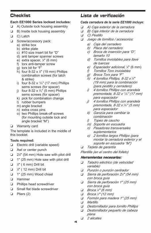
Alineación de la cerraduraexterior
Aligning the outsidelock
1. Place the outside lock unit on the door sothe screw studs (A) pass through the two 1⁄2" (13 mm) holes (see figure 7-1, 7-2).
2. Align the latch tailpiece (A) with the shoeretractor (B) of the cylindrical drive unit(D) by depressing the latch bolt slightly.Make sure that the latch prongs (C) andcylindrical drive unit (D) engage eachother as shown in figure 7-3.
1. Coloque la cerradura exterior en la puer-ta, de forma que las terminales de lostornillos largos (B) y los espárragos (A)atraviesen los 2 agujeros de 1⁄2" (13 mm)(véase las ilustraciones 7-1, 7-2).
2. Alinee la cola del pestillo (A) con el dispositivo retráctil (B) de la unidad cilíndrica de transmisión (D), ejerciendouna presión ligera en el pestillo.Asegúrese de que los dientes del pestillo(C) y la unidad cilíndrica de transmisión(D) se enganchan como lo muestra lailustración 7-3.
7
Prueba de la cerradura exterior
Testing the operation ofthe outside lock
1. Turn the outside knob clockwise to thestop position then release it.
2. Enter the factory-set combination:Depress buttons 2 and 4 at the sametime (release), then depress button 3(release). You should feel a “click” aseach button is depressed.
3. Turn the outside knob clockwise to thestop position and hold. Make sure thelatch is fully retracted, flush with the doorsedge.
4. Release the knob. The latch shouldreturn to the fully extended position.
1. Gire el pomo exterior hacia la derechahasta el tope y luego suéltelo.
2. Ponga la combinación que viene de fábrica: oprima los botones 2 y 4 almismo tiempo (suelte); luego oprima elbotón 3 (suelte). Con cada uno de losbotones que apriete, deberá oír unchasquido.
3. Gire el pomo exterior hacia la derechahasta el tope y manténgalo en esa posición. Asegúrese de que el pestillo serepliega totalmente, al ras con el bordede la puerta.
4. Suelte el pomo. El pestillo debe salir completamente.
8
7-1
17
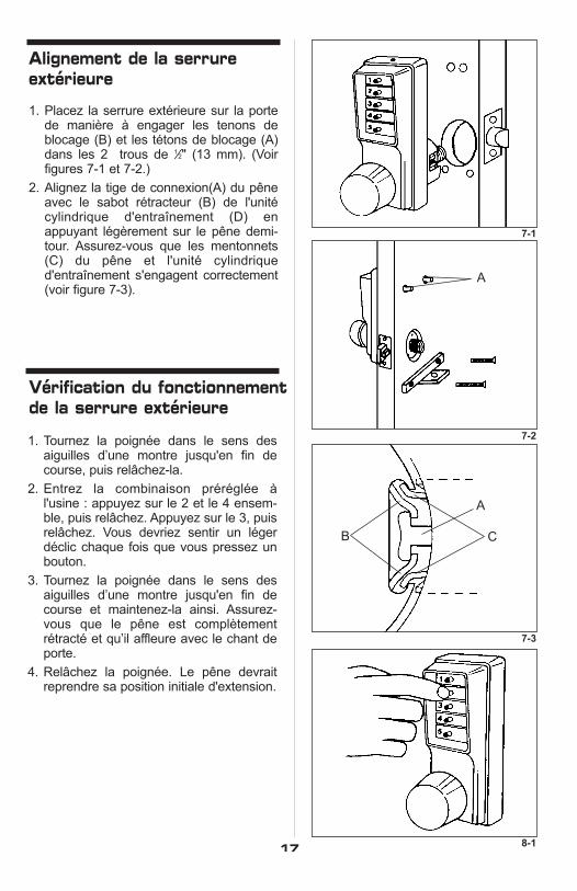
Alignement de la serrureextérieure
1. Placez la serrure extérieure sur la portede manière à engager les tenons deblocage (B) et les tétons de blocage (A)dans les 2 trous de 1⁄2" (13 mm). (Voir figures 7-1 et 7-2.)
2. Alignez la tige de connexion(A) du pêneavec le sabot rétracteur (B) de l'unitécylindrique d'entraînement (D) enappuyant légèrement sur le pêne demi-tour. Assurez-vous que les mentonnets(C) du pêne et l'unité cylindrique d'entraînement s'engagent correctement(voir figure 7-3).
Vérification du fonctionnementde la serrure extérieure
1. Tournez la poignée dans le sens des aiguilles d’une montre jusqu'en fin decourse, puis relâchez-la.
2. Entrez la combinaison préréglée à l'usine : appuyez sur le 2 et le 4 ensem-ble, puis relâchez. Appuyez sur le 3, puisrelâchez. Vous devriez sentir un légerdéclic chaque fois que vous pressez unbouton.
3. Tournez la poignée dans le sens desaiguilles d’une montre jusqu'en fin decourse et maintenez-la ainsi. Assurez-vous que le pêne est complètementrétracté et qu’il affleure avec le chant deporte.
4. Relâchez la poignée. Le pêne devraitreprendre sa position initiale d'extension.
7-2
7-3
8-1
A
A
CB

18
Instalación de la cerradurainterior
Installing the inside lock
1. Place the inside lock housing (C) as shown in figure 10-1. Make sure thedrive shaft pin (B) enters the corresp-ond-ing vertical slot (A) of the drive sleeve(see figure 10-1 and 10-2).
1. Coloque la caja interior de la cerradura(C) inclinada, tal como aparece en la ilus-tración 10-1. Asegúrese de que elpasador del eje de transmisión (B) entraen la ranura correspondiente vertical (A) del manguito del eje (véase la ilustración10-1 & 10-2).
10
Instalación de la cerraduraexterior
Installing the outsidelock
1. Shorten the Phillips screws (item “D” onchecklist) if necessary by breaking off atthe score marks (see figure 9-1).
2. Insert the two Phillips head screws (A)through the angle bracket (B) and into thetwo 1⁄4" (6 mm) holes in the door (see fig-ure 9-2).
3. Tighten the Phillips head screws (A),securing the outside lock assembly to thedoor (see figure 9-3).
1. Si es necesario, acorte los tornillos Phillips(artículo “d” de la lista de verificación),cortándolos por la línea de ruptura correspondiente (véase la ilustración 9-1).
2. Pase los dos tornillos Phillips (A) a travésdel soporte en escuadra (B) y métalos enlos dos agujeros de 1⁄4" (6 mm) taladradosen la puerta (véase la ilustración 9-2).
3. Ajuste los tornillos Phillips (A) fijando lacerradura exterior en la puerta (véase lailustración 9-3).
9

10-2
C
10-1
A
C
B
19
Installation de la serrureintérieure
1. Inclinez le boîtier de la serrure inté-rieure (C) comme sur la figure 10-1). Assurez-vous que la goupille de l'arbre d'entraînement (B) s'engage dans lafente correspondante verticale (A) du manchon d'entraînement (voir figure 10-1 & 10-2).
9-1
9-3
9-2
2" (51mm) 13⁄8" (35mm)
13⁄4" (45mm)
BA
A
Installation de la serrure extérieure
1. Si nécessaire, raccourcissez les visPhillips (accessoire D de la liste de vérification) en les brisant sur l’une deleurs stries (voir figure 9-1).
2. Insérez les deux vis Phillips (A) dans l'équerre de fixation (B) et dans les deuxtrous de 1⁄4" (6 mm) de la porte (voir figure 9-2).
3. Serrez les vis Phillips (A) fixant le boîtierextérieur sur la porte (voir figure 9-3).

KABA SIMPLEX®
LIMITED WARRANTYKaba Access Control warrants this product to be free from defects in materialand workmanship under normal use and service for a period of one (1) year. KabaAccess Control will repair or replace, at our discretion, locks found by KabaAccess Control analysis to be defective during this period. Our only liability,whether in tort or in contract, under this warranty is to repair or replace prod-ucts that are returned to Kaba Access Control within the one (1) year warrantyperiod.
This warranty is in lieu of and not in addition to any other warranty or condition,express or implied, including without limitation merchantability, fitness for pur-pose or absence of latent defects.
ATTENTION: This warranty does not cover problems arising out of improperinstallation, neglect or misuse. All warranties implied or written will be null andvoid if the lock is not installed properly and/or if any supplied component part issubstituted with a foreign part. If the lock is used with a wall bumper, the war-ranty is null and void. If a doorstop is required, we recommend the use of a floorsecured stop.
The environment and conditions of use determine the life of finishes on KabaAccess Control products. Finishes on Kaba Access Control products are subjectto change due to wear and environmental corrosion. Kaba Access Control cannotbe held responsible for the deterioration of finishes.
Authorization to Return Goods
Returned merchandise will not be accepted without prior approval. Approvalsand Returned Goods Authorization Numbers (RGA Numbers) are availablethrough our Customer Service department in Winston-Salem, NC1.800.849.8324. The serial number of a lock is required to obtain this RGANumber. The issuance of an RGA does not imply that a credit or replacement willbe issued.
The RGA number must be included on the address label when material is returned to the factory. All component parts including latches and strikes (evenif not inoperative) must be included in the package with return. All merchandisemust be returned prepaid and properly packaged to the address indicated.

KABA ACCESS CONTROL
2941 INDIANA AVENUE
WINSTO
N-SALEM, NC 27199-3770
NO POSTAGE
NECESSARY
IF MAILED
IN THE
UNITED STATES
BU
SIN
ES
S R
EP
LY M
AIL
FIRST-CLASS MAIL
PERMIT NO. 1563
POSTAGE WILL BE PAID BY ADDRESSEE
WINSTON-SALEM, NC

Thank yo
u for p
urch
asing our p
roduct. In
order to
protect yo
ur investm
ent an
d to en
able u
s to better
serve you in the future, please fill out this registrationcard
and retu
rn it to
Kaba A
ccess Contro
l, or
register o
nline at w
ww
.kabaaccess.co
m.
This lock w
ill be used in
what ty
pe of facility?
oCom
mercial B
uildingo
Industrial/ Manufacturing
oAirport
oCollege
/University
oGovernm
ent/Military
oSchool/Educational
oHospital/H
ealthcareo
Other (please specify)
What area is bein
g secured w
ith th
is lock? (e.g. Front D
oor, Com
mon D
oor, Exercise R
oom)
This lock is:
oNew Installation
oReplacing a conventional keyed lock
oReplacing a K
aba Mechanical P
ushbutton Lock
oReplacing a K
aba Electronic A
ccess Control
oReplacing a K
eyless Lock other than Kaba
How
did you
learn abou
t Kaba A
ccess Con
trol Push
button
Locks?
oAdvertisem
ento
Previous U
seo
Internet/Web
oAnother U
se
oLocksm
itho
Maintenance
oTraining C
lasso
Other (please specify)
What w
as you
r reason for bu
yin
g this lock?
Who in
stalled your lock?
oLocksm
itho
Maintenance
oOther
oC
heck h
ere if you w
ould like m
ore information
on K
aba Access C
ontrol locks.
Nam
e
Position
Com
pany
Address
City
State
ZIP (Postal C
ode)
Country
Phone
Nam
e of Dealer P
urchased From
Date of P
urchase
Lock Model N
umber
RE
GIS
TR
AT
ION
CA
RD

Notes

20
Prueba de la cerradura interior
Testing the operation ofthe inside lock
1. Turn the inside knob all the way until itstops, then release it.
2. Enter the factory set combination:depress buttons 2 and 4 simultaneously(release), then depress button 3 (release)(see figure 11-1).
3. Turn the knob clockwise to the stop position. As the knob turns, the latch willretract. Make sure the latch retracts fully(flush with the latch face plate).
4. Release the knob. The latch will return tothe fully extended position.
1. Gire el pomo interior hasta el tope y suéltelo.
2. Introduzca la combinación que viene defábrica: oprima los botones 2 y 4 almismo tiempo (lanzamiento); luego opri-m a el botón 3 (lanzamiento)(véase la ilus-tración 11-1).
3. Gire el pomo hacia la derecha hasta eltope. El pestillo se replegará. Asegúresede que se queda totalmente replegado(al ras con la placa de recubrimiento).
4. Suelte el pomo. El pestillo debe volver asalir completamente.
11
Instalacion de la cerradura dellado de adentro Continuación
Installing the inside lockContinued
2. Use the #10 insert bit (B) included in theaccessory pack (item “C” on checklist) toscrew in the two anti-tamper spannertype screws (A) (item “D” on checklist)through the face of the inside lock (seefigure 10-3).
3. Use the torx anti-tamper tool bit included in the accessory pack (item “G”on checklist) to install the anti-tampertorx-type screw (A) (item “F” on checklist)through the bottom of the lock into theangle bracket. (see figure 10-4).
2. Utilice la broca de inserción número 10(B) que viene en el paquete de acceso-rios (artículo “c” de la lista de verificación)para introducir los dos tornillos invio-lables para llave de tuercas (A) (artículo“d” de la lista de verificación), a través dela cara de la cerradura interior (véase lailustración 10-3).
3. Utilice la broca Torx que viene en elpaquete de accesorios (artículo “g” de lalista de verificación) para instalar el tornillo Torx inviolable (A) (artículo “f” de lalista de verificación) en el soporte enescuadra, atravesando la parte inferior dela cerradura. Véase la ilustración 10-4.
10

21
Vérification du fonctionnementde la serrure intérieure
1. Tournez la poignée intérieure jusqu'en finde course puis relâchez-la.
2. Entrez la combinaison préréglée à l'usine : appuyez sur le 2 et le 4 ensemble, puis relâchez. Appuyez sur le3, puis relâchez (voir figure 11-1).
3. Tournez la poignée dans le sens des aiguilles d’une montre jusqu'en fin decourse. Tandis que la poignée pivote, lepêne se rétracte. Assurez-vous que lepêne se rétracte et affleure la têtière.
4. Relâchez la poignée. Le pêne reprend saposition initiale d'extension.
10-3
11-1
B
A
B
10-4
A
Installation de la serrureintérieure Suite
2. Avec l'outil rapporté n° 10 (B) (acces-soire C de la liste de vérification), serrez les deux vis à écrou inviolables (accessoire D de la liste devérification) sur le devant de la serrure(voir figure 10-3).
3. À l'aide de l'outil rapporté contenudans le jeu d’accessoires (accessoireG de la liste de vérification), serrez lavis Torx inviolable (A) (accessoire F dela liste de vérification) sur ledessous de la serrure dans l'équerre de fixation (voir figure 10-4).

22
Instalación del cerraderoInstalling the strike
1. Mark the location of the strike on the doorframe (A) according to the template.Make certain that the line through thescrew holes of the strike are aligned withthe line through the screw holes on theface of the latch when the door is closed(see figure 12-1).
2. Mortise the door frame (for strike box) toa minimum depth of 3⁄4" (19 mm). This willguarantee that the latch (D) can be fullyextended into the door frame if using anoptional 3⁄4" (19 mm) throw latch. (Thesupplied KABA strike box must be used).
3. Place the strike box (B) in the mortisedcutout. Secure the strike plate (C) withtwo of the 3⁄4" (19 mm) screws (E) provid-ed (item “H” on checklist). If necessary,draw a line around the strike. Use this lineas a guide to cut out a minimum of 1⁄16" (2mm) of material or enough to make thestrike plate flush with the door frame.
Caution: Check the operation of the latchby making sure that the dead latch stopsagainst the strike plate, and does not slipinto the strike opening when the door isclosed (A) (see figure 12-2). If this situationoccurs, then a total lockout may result. Thiswill cancel our warranty of the complete lockmechanism.
Note: If there is a gap between the edge ofdoor and the frame (or in the case of doubledoors, the edge of the door and the edge ofthe door) of more than 1⁄4" (6 mm) the deadlatch will fail to engage the strike plate.
If necessary, correct the door over-travel byusing the rubber bumpers as described inthe "Preserving the latch" section 14.
1. Marque el lugar donde va el cerradero enel marco de la puerta (A), siguiendo lasindicaciones de la plantilla. Asegúresede que la línea que atraviesa los agujerosde los tornillos del cerradero está alinea-da con la línea que atraviesa los agujerosde los tornillos de la chapa del pestillo cuando la puerta está cerrada (véase lailustración 12-1).
2. Corte el marco de la puerta para empo-trar la caja del cerradero hasta una profundidad mínima de 3⁄4" (19 mm). Estogarantizará que el pestillo (D) entre completamente en el marco de la puertacuando la longitud del pestillo es deopcional 3⁄4" (19 mm). Deberá usarse lacaja del cerradero suministrada porKABA.
3. Coloque la caja del cerradero (B) en elhueco que ha hecho para empotrarla.Fije la placa del cerradero (C) con dos delos tornillos de 3⁄4" (19 mm) provistos (E)(artículo “h” en la lista de verificación). Sies necesario, dibuje el contorno del cerradero. Use esta línea como referen-cia para cortar un mínimo de 1⁄16" (2 mm)de material o lo suficiente para que el cerradero quede al ras con el marco de lapuerta.
Advertencia: Verifique el funcionamientodel pestillo al quedar la puerta cerrada, asegurándose de que el pin de seguridaddel mismo queda detenido por la placa del cerradero y no entra en la abertura (A) (verla ilustración 12-2). Si esto ocurre, la puertapuede bloquearse completamente. En esecaso, la garantía de la cerradura quedaráanulada.
Observación: Si hay un espacio de más de1⁄4" (6 mm) entre el borde y el marco de lapuerta (o en el caso de puertas dobles, elborde de una puerta y el borde de la otra) elpin de seguridad del pestillo no lograráenganchar la placa del cerradero. Si es necesario, corrija el exceso de batiente dela puerta mediante topes de caucho talcomo se describe en la sección 14.
12

23
12-1
12-2
Installation de la gâche
1. Marquez l'emplacement de la gâche surl’huisserie (A) à l'aide du gabarit. Lorsquela porte est fermée, assurez-vous que laligne de repère des trous pour les vis dela gâche est alignée avec la ligne derepère des trous pour les vis de la têtière(voir figure 12-1).
2. Pratiquer une mortaise dans l’huisserie(en prévision du boîtier de gâche) de 3⁄4"(19 mm) de profondeur minimum qui per-mettra au pêne de s'engager complètement dans son logement s’ils’agit d’un pêne de 3⁄4" (19 mm) optionel.(Utilisez le boîtier de gâche KABA fourni).
3. Placez le boîtier de gâche (B) dans sonlogement mortaisé. Fixez la gâche (C) àl'aide des deux vis de 3⁄4" (19 mm) (E)(accessoire H de la liste de vérification).Tracez le pourtour de la gâche si nécessaire. Utilisez cette ligne de repèrepour enlever environ 1⁄16" (2 mm) de boispour que la gâche affleure l’huisserie.
Attention: Assurez-vous que le pêne demi-tour vient s'appuyer contre la gâche.S’il glisse dans le logement de la gâchelorsque la porte est fermée (voir figure 12-2),la serrure pourrait interdire l'accès. Unemauvaise installation annulerait toutegarantie du mécanisme de verrouillage
N.B. S'il y a un espace de plus de 1⁄4" (6 mm)entre le chant de porte et l’huisserie (ouentre les deux chants s'il s'agit d'une porte àdeux vantaux), le pêne ne pourra pas s'engager dans la gâche.
Si nécessaire, corrigez l’excès de fin decourse de la porte en installant des butéesde caoutchouc comme décrit dans l’étape14, Alignement entre la porte et l’huisserie.
A
A
B
C
DE
3
X

24
The door must be open.
The combination for the outside and insidelocks must be changed independently.Follow the same procedure for the outsideand inside.
1. Use the torx anti-tamper tool bit provided item "G" on checklist to removethe tamperproof screw from the top ofthe pushbutton housing (see figure 13-1).
2. Turn the knob clockwise to the stop position, then release.
3. Enter the existing combination. On newinstallations, enter the factory-set combination: depress buttons 2 and 4simultaneously (release), then depress button 3 (release). You should feel a“click” as each button is depressed.
4. Insert the pick provided (item “K” onchecklist) through the screw hole andlightly depress the slide inside — you willfeel a slight “click”. Remove the pick (seefigure 13-2).
5. Turn the knob clockwise all the way untilit stops, then release.
6. Choose your new combination, write it onpage 28, then enter the new combination— press buttons carefully (a slight clickshould be felt as each button isdepressed) (see figure 13-3).
Note: You can use one button or all five for acombination, but each button can only beused once. You can press two buttons simul-taneously as a step in the combination.
7. Turn the knob clockwise once, to thestop position, hold in position andmake sure the latch is retracted.Release the knob. Turn the knobclockwise again to the stop position.At this point, the latch should notretract unless you enter the new combination (see figure 13-4).
La puerta debe estar abierta.
Las combinaciones para las cerraduras interior y exterior deben cambiarse sepa-radamente. Siga el mismo procedimientopara ambos lados.
1. Utilice la broca Torx (artículo “g” en lalista de verificación) para sacar el tornilloinviolable de la parte superior de la cajadonde están los botones pulsadores(véase la ilustración 13-1).
2. Gire el pomo hacia la derecha, hasta eltope, y luego suéltelo.
3. Introduzca la combinación programada.En las instalaciones nuevas, utilice lacombinación de fábrica: oprima losbotones 2 y 4 simultáneamente, suelte,luego oprima el 3 y suelte. Cada vez queoprima un botón, deberá oír un chasqui-do.
4. Pase la ganzúa suministrada (artículo “k”de la lista de verificación) a través del agujero para el tornillo y ligeramenteoprima la platina hacia adentro, hastaque oiga un leve “chasquido”. Saque laganzúa (véase la ilustración 13-2).
5. Gire el pomo hacia la derecha, hasta eltope, y luego suéltelo.
6. Escoja una combinación nueva, escríbalaen la página 28 y luego introduzca lanueva combinación. Oprima los botonescuidadosamente (al oprimir cada uno delos botones, se debería oír un levechasquido)(véase la ilustración 13-3).
Nota: Para la combinación puede utilizarseun botón o los cinco, pero cada botón sólopuede utilizarse una vez. En una etapa dela combinación puede apretar dos botoneso más simultáneamente.
7. Gire una vez hacia la derecha el pomo, ala posición de parada ; manténgalo enesa posición y asegúrese de que elpestillo está replegado. Suelte el pomo.Gírelo otra vez hacia la derecha hasta eltope. Ahora, el pestillo no debería reple-garse hasta que coloque la nueva combi-nación (véase la ilustración 13-4).
13 Cambio de la combinaciónChanging the combination

25
13-1
13-2
13-3
13-4
Gardez la porte ouverte.
Vous devez changer la combinaison sur lesserrures extérieure et intérieure. Procédezde la même façon pour les deux serrures.
1. À l'aide de l'outil rapporté fourni (acces-soire “G” de la liste de vérification)desserrez la vis inviolable sur le dessusdu boîtier (voir figure 13-1).
2. Tournez la poignée dans le sens des aiguilles d’une montre jusqu'en fin decourse et relâchez-la.
3. Entrez la combinaison existante. S'il s'agit d'une première utilisation, appuyezsur le 2 et le 4 ensemble, puis relâchez.Appuyez sur le 3, puis relâchez. Vousdevriez sentir un léger déclic chaque foisque vous pressez un bouton.
4. Insérez le crochet (accessoire K de laliste de vérification) dans l'orifice de la viset appuyez doucement sur le coulisseauinterne (vous sentirez un léger déclic).Retirez le crochet (voir figure 13-2).
5. Tournez la poignée dans le sens des aiguilles d’une montre jusqu'en fin decourse puis relâchez-la.
6. Choisissez la nouvelle combinaison,écrivez-la à la page 28 etentrez-la :appuyez à fond sur les boutons (vousdevriez sentir un léger déclic chaque foisque vous pressez un bouton).
N.B. Vous pouvez utiliser un seul ou les cinqboutons. Vous ne pouvez utiliser chaquebouton qu'une seule fois. Vous pouvez appuyer sur deux boutons ou plusen même temps.
7. Tournez la poignée dans le sens des aiguilles d’une montre jusqu'en fin de course et maintenez-la ainsi. Assurez-vous que le pêne est rétracté. Relâchez
la poignée. Tournez à nouveau la poignée dans le sens des aiguilles d’une montre jusqu'en fin de course. Le pêne ne doit pas se rétracter, à moins que vous n'entriez la nouvelle combinaison (voir figure 13-4).
Changement de la combinaison
A

26
Cambio de la combianciónContinuación
8. Vuelva a colocar el tornillo inviolable en laparte superior de la cerradura.
9. Repita las etapas 1 a 8 para el otro ladode la puerta.
The door to frame relationship is critical forthe performance and durability of the latch mechanism. The vertical and horizon-tal center lines are important when position-ing the lock, the strike, and the latch, andmust be according to ANSI* standardA115.2. To insure proper installation, youmust use the supplied strike plate.
Rubber bumpers (supplied with the lock)may be required to properly align the door.The adjustment becomes more significantwith metal frames, wood doors, and fillerplates when replacing existing hardware.Figure 14-1 shows the proper alignmentbetween the door, the frame, the latch andthe strike plate.
When the door rests against the door stop(A), the dead latch (B) should seat againstthe strike plate. At this point, you will notice atolerance of 3⁄32" (2 mm), basic according toANSI standards. If the door travels beyondthis tolerance, the dead latch may slip intothe strike box with the anti-friction device,causing the latch to jam, and create a lock-inand lock-out condition. (see A in figure 14-2).
This condition can be prevented by addingbumpers to the door stop.
* American National Standards Institute —contact KABA for further information.
La relación entre la puerta y el marco esmuy importante para el rendimiento y la durabilidad del mecanismo que acciona elpestillo. Las líneas centrales, horizontales yverticales, son importantes cuando se colo-ca la cerradura, el cerradero y el pestillo.Deben responder a la norma ANSI* A115.2.Para realizar una instalación adecuada,deberá usarse la placa del cerradero pro-vista.
Quizá se requieran topes de caucho (quevienen con la cerradura) para alinear adecuadamente la puerta. El ajuste es másimportante en los casos de marcos demetal, puertas de madera y placas de rel-leno, cuando se cambian los herrajes exis-tentes. La ilustración 14-1 muestra la alin-eación adecuada entre la puerta, el marco,el pestillo y la placa del cerradero.
Cuando la puerta llega hasta su tope (A), elpin de seguridad (B) del pestillo debe apoyarse contra la placa del cerradero. Enese momento notará que existe una toler-ancia de 3⁄32" (2 mm), tolerancia estándarsegún las normas ANSI. Si la puerta giramás allá de esta tolerancia, el pin de seguri-dad puede deslizarse en la caja del cer-radero con el dispositivo antifricción, haciendo que elpestillo se atasque y bloqueando el accesotanto desde el interior como desde el exteri-or (véase A en la ilustración 14-2).
Esta situación puede prevenirse añadiendootros topes al tope de la puerta.
* Instituto Nacional Estadounidense deNormas - para más información sírvaseentrar en contacto con KABA.
Changing the combination Continued
8. Replace the tamperproof screw in thetop of the lock unit.
9. Repeat steps 1-8 for other side of door.
13
Mantenimiento del pestilloPreserving the latch14

27
Changement de la combinaison Suite
8. Remettez la vis antivol dans le trouprévu à cet effet sur le dessus du boîtier.
9. Répétez les étapes 1 à 8 pour l’autrecôté de la porte.
L'alignement entre la porte et le jambage estprimordial pour le bon fonctionnement et ladurabilité du mécanisme de verrouillage. Ilest très important de respecter les normesANSI* A115.2 ainsi que les axes vertical ethorizontal au moment de poser la serrure, lagâche et le pêne. Pour une installationadéquate, utilisez la gâche fournie.
Vous aurez peut-être à utiliser les butées decaoutchouc fournies pour aligner la portecorrectement. L'ajustement est encore plusimportant s'il s'agit de remplacer du matérieldéjà en place sur des huisseries de métal,des portes en bois et des plaques de rcou-vrement. La figure 14-1 illustre le bon aligne-ment qui doit exister entre la porte, le jam-bage, le pêne et la gâche.
Quand la porte vient s'arrêter contre labutée de porte, le pêne demi-tour doit s'appuyer contre la gâche. Vous pourreznoter un jeu de 3⁄32" (2 mm), norme définiepar l'ANSI. Si la course de la porte n'est paslimitée, le contre-pêne de sécurité risque deglisser dans le logement de la gâche avec ledispositif antifriction, interdisant l'accès del'intérieur comme de l'extérieur (voir A figure 14-2).
Vous pouvez limiter l'ouverture de la porteen installant des butées de caoutchouc surl’arrêt de porte.
* American National Standards Institute(communiquez avec KABA pour obtenir deplus amples renseignements)
Alignement entre la porte etle jambage
14-1
1 15⁄16" (49mm)
3⁄32" (2mm)
11⁄32" (9mm)
1 3⁄4" (44mm)
B
A
14-2
A
3
X

28
Funcion de paso libreContinuación
Preserving the latchContinued
Instalación de los topes de caucho (provis-tos en el juego de accesorios - artículo “L”en la lista de verificación).
1. Cierre la puerta y empújela, asegurán-dose de que el pin de seguridad seapoya en la placa del cerradero.
2. Colocándose del lado donde va el topede la puerta, compruebe si quedan espa-cios entre la puerta y el tope, en los treslados del marco (izquierdo, derecho ysuperior). Marque los lugares donde losespacios son de unos 3⁄16" (5 mm) (ver lafigura 14-2).
3. Asegúrese de que estos lugares notienen grasa ni polvo.
4. Saque la capa protectora de los topes sintocar la superficie adhesiva y péguelosen los lugares que ha marcado.
5. Antes de hacer una prueba, deje pasar24 horas para que el adhesivo cumpla su función. Durante este período la puertapuede abrirse y cerrarse normalmente.
14
Installing Rubber Bumpers (provided inaccessory pack – item “L” on checklist)
1. Close door and apply pressure makingsure the dead latch rests on the strikeplate.
2. Standing on the door stop side of thedoor, check for gaps between the doorand the door stop on all three sides ofthe frame (left, right, and top). Marklocations where the gaps are approxi-mately 3⁄16" (5 mm) (see figure 14-2).
3. Make sure these locations are free ofgrease and dust.
4. Peel the bumpers from their protectivebacking without touching the adhesivesurface and stick them on the markedlocations on the door stop.
5. Allow 24 hours for adhesive to set beforetesting. Door may be operated normallyduring this time.
Registro de combinacionesCombination settingrecord
Combination # Date
____________________________
____________________________
____________________________
____________________________
____________________________
____________________________
____________________________
____________________________
____________________________
No de Combinación # Fecha____________________________
____________________________
____________________________
____________________________
____________________________
____________________________
____________________________
____________________________
____________________________
15

29
Alignement entre la porte etle jambage Suite
Installation des butées de caoutchouc qui setrouve dans le paquet d’accessoires (acces-soire J de la liste de vérification)
1. Fermez la porte et appliquer une pression en vous assurant que le pênedemii-tour vient s'appuyer contre lagâche.
2. En vous plaçant du côté de l’arrêt deporte, vérifiez le jeu entre la porte et labutée de porte sur les trois côtés del’huisserie (gauche, droite et dessus).Marquez tout emplacement dont le jeuest d'environ 3⁄16" (5 mm) (voir figure 14-2.)
3. Assurez-vous que ces emplacementssont dépourvus de graisse ou de poussière.
4. Enlevez la bande adhésive qui recouvreles butées de caoutchouc sans toucher àla surface collante et fixez-les à l'emplacement marqué.
5. Attendez 24 heures avant de vérifier lapose. Vous pouvez toutefois ouvrir et fermer la porte entre temps.
Registre des combinaisons
No de la combinaison Date
____________________________
____________________________
____________________________
____________________________
____________________________
____________________________
____________________________
____________________________
____________________________
14-2

30
No existe ningún procedimiento paraaveriguar la combinación desde la partedelantera de la cerradura. Una combi-nación perdida deberá anularse quitando lacámara de combinación de la caja de la cer-radura; luego se podrá colocar una nueva combinación.
Nota: El procedimiento siguiente puede utilizarse tanto para la cerradura interiorcomo exterior.
1. Quite la placa posterior de la cerradurasacando los cuatro tornillos que van enesa placa.
2. Levante la palanqueta (A) de la cámarapara sacarla del eje de control (B),haciendo palanca con un destornilladorde cabeza plana (véase la ilustración 16-1).
3. Quite el cojinete del eje (C).
4. Quite la cámara de combinación (D)sacando los dos tornillos Phillips (E) quehay en cada extremo de la cámara.
5. Quite la cubierta echada a un lado 3 delcompartimiento (A) de la cámara quelleva la marca “KABA” (véase la ilus-tración 16-2) golpeando suavemente conun destornillador el borde de la cubiertaen el extremo del eje de control de lacámara (A) (véase la ilustración 16-3)para separarla de las juntas (B).
6. Ponga la cámara sobre un lado como seilustra en figura 16-4.
7. Mediante pinzas (u otra herramienta), quiteel aro “E” (B) del saliente de la placa dedesenganche (A) (ver figura 16-4),después, levante suavemente el extremode la placa de desenganche (C) delsaliente (A).
Nota: La placa de desenganche (C) estásometida a la tensión de un muelle y se levantará fácilmente si se le empuja hacia laizquierda para disminuir la tensión. Gire laplaca de desenganche (C) lo suficientecomo para liberar los engranajes (D), perono más allá de donde se indica en la figura16-5.
8. Apriete en la varilla de cierre (E). Ahora,los engranajes (D) pueden girar libre-mente (ver figura 16-6).
Clearing a lost combination
Anulacion de una combinación perdida16
There is no procedure for finding anunknown combination from the front of thelock. A lost combination must be cleared byremoving the combination chamber from thelock housing, then a new combination canbe set.
Note: The following procedures can beused for both the inside and outside lockassemblies.1. Remove the back plate from the lock by
removing the four back plate screws.2. Lift the chamber linkage (A) off of the con-
trol shaft (B) by prying up with a flat blade screwdriver (see figure 16-1).
3. Remove the shaft bushing (C).4. Remove the combination chamber (D) by
removing the two Phillips head screws(E) at each end of the combination cham-ber.
5. Remove the 3 sided chamber cover (A)marked “KABA” (see figure 16-2) by gen-tly tapping the lip of the chamber cover atthe control shaft end of the chamber (A)(see figure 16-3) with a screwdriver todetach it from the staked joints (B).
6. Lay the chamber down on its side as shownin figure 16-4.
7. With tweezers, or other tool, slide the “E”ring (B) off the unlocking slide stud (A)(see figure 16-4), then gently lift the endof the unlocking slide (C) over the unlock-ing slide stud (A).
Note: The unlocking slide (C) is underspring tension and will be easier to lift ifpushed to the left to ease tension. Swing theunlocking slide (C) sufficiently to clear thegears (D), no further than shown in figure16-5. 8. Depress the lockout slide (E). The gears
(D) are now free to rotate see figure 16-6.9. Turn each gear (D) so that the gear
pockets (F) are aligned as in figure 16-6.10.Return the unlocking slide (C) over the
unlocking slide stud (A) while making certain the five toes (G) are engaged inthe five gear pockets (F). If necessary,adjust each gear to make proper align-ment between toes and gear slots (seefigures 16-6 & 16-7).

31
Il est impossible de retrouver une combinai-son perdue à partir du clavier de la serrure. Pour annuler une combinaison perdue, vous devez enlever la chambre àcombinaison du boîtier de serrure, puis entr-er une nouvelle combinaison.
N.B. : les instructions suivantes peuventêtre exécutées pour les côtés extérieur etintérieur.
1. Enlevez le palastre en desserrant lesquatre vis .
2. Soulevez le levier (A) de la chambre horsde l’arbre de commande (B) à l'aide d'untournevis à lame plate (voir figure 16-1).
3. Enlevez la bague de l'arbre (C).
4. Démontez la chambre à combinaison (D)en desserrant les deux vis Phillips (E) àchaque extrémité de la chambre à combinaison.
5. Enlevez les 3 côtés du couvercle (A) dela chambre sur lequel est inscrit “KABA’’(voir figure 16-2) en tapotant avec la lamed’un tournevis sur la languette du couvercle de la chambre à l’extrémité del’arbre de commande de la chambre (A)(voir figure 16-3) pour la désengager despattes d'attache (B).
6. Mettez la chambre à combinaison à platcomme indiqué sur la voir figure 16-4.
7. À l'aide de petites pinces ou d’un autreoutil, faites glisser la bague en E (B) horsdu goujon du coulisseau de déverrouil-lage (voir figure 16-4), puis soulevezdoucement l’extrémité de celui-ci (C) au-dessus du goujon (A).
N.B. : Le coulisseau de déverrouillage (C)est à ressort; aussi, il sera plus facile dele soulever vers la gauche. Tirez sur lecoulisseau de déverrouillage (C) demanière à laisser voir les engrenages (D)(voir figure 16-5).
8. Appuyez sur le coulisseau de verrouil-lage (E). Les engrenages (D) peuventfonctionner librement (voir figure 16-6).
9. Tournez les engrenages (D) de manièreà les aligner avec leur logement respectif(F) comme sur la figure 16-6.
Annulation d'une combinaisonperdue
16-1
16-3
16-2
16-4
A
EB
C
D
A B
A
B
ABC

32
9. Gire cada engranaje (D) para que cadaválvula del engranaje (F) se alinee, talcomo aparece en la figura 16-6.
10. Vuelva a colocar la placa de desen-ganche (C) sobre los salientes (A) ase-gurándose de que los cinco dientes (G)se quedan engranados en sus lugaresrespectivos (F). Si es necesario, ajustecada engranaje para alinear correcta-mente los dientes y las válvulas delengranaje (ver figuras 16-6 y 16-7).
Vuelva a instalar el aro “E” (B) en el saliente(A). Una vez que la cámara quede comoaparece en la ilustración 16-7, se podrávolver a montar en la caja de la cerradura.
No trate de poner una combinación hasta quetoda la unidad se haya vuelto a montar.
MONTAJE1. Vuelva a colocar la cubierta de la cámara
(A) que lleva la marca “KABA”. Asegúrese de que las juntas (B) en las dos placasde los extremos entran en las dos ranuras de la cubierta posterior (ver lailustración 16-2).
2. Vuelva a colocar el cojinete del eje (B) conla parte plana hacia arriba (ver figura 16-8).
3. Fije la cámara (D) con los dos tornillosPhillips (E) que había sacado antes (verfigura 16-8).
4. Vuelva a colocar la palanqueta de lacámara (C) en el eje de control (F) (verfigura 16-8).
5. Vuelva a colocar la placa posterior y fíjelacon los cuatro tornillos correspondientes.
PUESTA DE LA COMBINACIÓNEjecute los pasos siguientes en el orden indicado.
1. Gire el pomo exterior hacia la derechahasta el tope y luego suéltelo.
2. Introduzca la nueva combinación.
3. Gire el pomo exterior hacia la derechahasta el tope, asegurándose de que elpestillo se repliega completamente; luegosuelte el pomo para activar la nueva com-binación.
4. Repita las etapas 2 y 3 antes de cerrar lapuerta para confirmar la combinación.
Clearing a lost combination Continued
Anulacion de una combinaciónperdida Continuación16
Resecure the “E” ring (B) on the unlockingslide stud (A). Your chamber now resemblesfigure 16-7 and is ready for reassembly intothe lock housing.
Do not attempt to set a combination until thecomplete unit has been reassembled.
REASSEMBlING THE lOCK
1. Resecure the chamber cover (A) markedKABA. Make sure the staked joints (B) onboth end plates fit through both slots onthe back cover (see figure 16-2). Re-stake joints.
2. Resecure the shaft bushing (B) with flatside facing up (see figure 16-8).
3. Secure the chamber (D) with the twoPhillips head screws (E) you removedearlier (see figure 16-8).
4. Resecure the chamber linkage (C) ontothe control shaft (F) (see figure 16-8).
5. Replace the back plate and secure it withthe four back plate screws.
SETTING THE COMBINATION
Perform the following steps in order.
1. Turn the outside knob once clockwise tothe stop position then release.
2. Enter the new combination.
3. Turn the outside knob clockwise to thestop position, make sure the latch is fullyretracted, then release the knob to lock inthe new combination.
4. Repeat steps 2 & 3 before closing yourdoor to confirm code setting.

33
10Replacez le coulisseau de déverrouillage(C) sur le goujon (A) en vous assurant queles cinq pattes (G) sont bien engagéesdans leur logement respectif (F). Si néces-saire, ajustez les engrenages pour align-er correctement les pattes et les rainures(voir figures 16-6 et 16-7.)
Replacez la bague en E sur le goujon. Votrechambre à combinaison ressemble main-tenant à la figure 16-7 et est prête à recevoirson couvercle.
N’essayez pas d'entrer une nouvelle combinaison tant que la serrure n'est pascomplètement remontée.
RÉASSEMBlAGE dE lA SERRURE
1. Replacez le couvercle (A) de la chambresur lequel est inscrit KABA. Assurez-vousque les pattes d'attache (B) s'engagentdans les fentes du couvercle arrière (voirfigure 16-2).
2. Replacez la bague de l'arbre (B) , côté platsur le dessus (voir figure 16-8).
3. Fixez la chambre à combinaison (D) àl'aide des deux vis Phillips retirées plus tôt(voir figure 16-8).
4. Replacez les leviers (C) de la chambre surl'arbre de commande (F) (voir figure 17-8).
5. Remontez le palastre et fixez-le à l'aidedes quatre vis.
ENREGISTREMENT dE lA COMBINAISON
Suivez les instructions ci-dessous:
1. Tournez la poignée extérieure dans lesens des aiguilles d’une montre jusqu'enfin de course, puis relâchez-la.
2. Entrez la nouvelle combinaison.
3. Tournez la poignée extérieure dans lesens des aiguilles d’une montre jusqu'enfin de course. Assurez-vous que le pêneest complètement rétracté, puis relâchezla poignée pour enregistrer la nouvellecombinaison.
4. Répétez les étapes 2 et 3 avant de fermerla porte pour confirmer l’enregistrement.
Annulation d'une combinaisoninconnue Suite
16-5
16-6
16-7
D
C
E
D C
AC B
G
F
16-8
AE
F B
C
D

34
Cuando se gira el pomo exterior o inte-rior, el pestillo siempre se repliega sinapretar ningún botón.
La cerradura está en la combinacióncero.
Siga el procedimiento indicado paracambiar la combinación, etapa 14, página 26, omitiendo la etapa 3 (nointroduzca la combinación existente).
Después de introducir la nueva combinación, la cerradura sólo funcionauna vez, luego no abre.
Al cambiar la combinación, los botonesno se apretaron completamente.
Consulte la etapa 17, en la página 34 -Anulación de una combinación perdida.
Para obtener asistencia, puede llamar al 1-800-849-TECH (8324) o
336-725-1331.
Fuera de EE.UU. y Canadá, diríjase asu distribuidor KABA.
Turning outside or inside knob alwaysretracts latch without depressing any buttons.
Lock is in zero combination.
Follow the procedure for changing a combination (Step 14 on page 26)except omit step 3 (do not enter theexisting combination).
After entering a new combination, thelock works one time only; then the lockfails to open.
Buttons of intended combination werenot fully depressed when changing combination.
Refer to (Step 17 on page 34) -"Clearing a lost combination".
For further assistance call: 1-800-849-8324 or 336-725-1331
Outside U.S.A. and Canada pleasecall your KABA dealer.
Troubleshooting Localización y reparación deaverías17
?
Î
+
?
Î
+
?
Î
+
?
Î
+
?= Symptom/problem= Síntoma/problema= Problème
= Possible cause= Causa posible= Cause possible= Remedy= Solución= Solution
Î
+

35
Sous l'action de la poignée extérieureou intérieure, le pêne se rétracte sansque vous n'ayez appuyé sur aucunbouton.
La serrure ne possède aucune combi-naison.
Vous reportez à l’étape 14,Changement de la combinaison, page26. Ne tenez pas compte de l'étape 3(combinaison déjà existante).
Dès que la nouvelle combinaison estentrée, la serrure fonctionne une première fois, puis interdit l'accès par lasuite.
Les boutons-poussoirs de la combinai-son choisie n'ont pas été pressés complètement au moment du changement de la combinaison.
Reportez-vous à l’étape 17, page 34,Annulation d'une combinaison inconnue.
Pour pour plus de reseignementscomposer : 1-800-TECH (8324)
ou 336-725-1331
Pour l’extérieur des É.-U. et leCanada, adressez-vous à votre dis-
tributeur KABA.
Dépannage
?
Î
+
?
Î
+

Kaba Access Control2941 Indiana AvenueWinston-Salem, NC 27105 USATel: 800.849.8324 or 336.725.1331Fax: 800.346.9640 or 336.725.3269
www.kabaaccess.com PKG2282 0910