Embed Size (px)
Citation preview
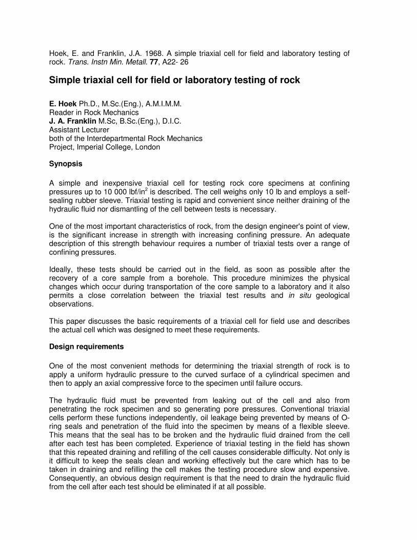
Hoek, E. and Franklin, J.A. 1968. A simple triaxial cell for field and laboratory testing of rock. Trans. Instn Min. Metall. 77, A22- 26
Simple triaxial cell for field or laboratory testing of rock
E. Hoek Ph.D., M.Sc.(Eng.), A.M.I.M.M. Reader in Rock Mechanics J. A. Franklin M.Sc, B.Sc.(Eng.), D.I.C. Assistant Lecturer both of the Interdepartmental Rock Mechanics Project, Imperial College, London
Synopsis
A simple and inexpensive triaxial cell for testing rock core specimens at confining pressures up to 10 000 lbf/in2 is described. The cell weighs only 10 lb and employs a self-sealing rubber sleeve. Triaxial testing is rapid and convenient since neither draining of the hydraulic fluid nor dismantling of the cell between tests is necessary. One of the most important characteristics of rock, from the design engineer's point of view, is the significant increase in strength with increasing confining pressure. An adequate description of this strength behaviour requires a number of triaxial tests over a range of confining pressures. Ideally, these tests should be carried out in the field, as soon as possible after the recovery of a core sample from a borehole. This procedure minimizes the physical changes which occur during transportation of the core sample to a laboratory and it also permits a close correlation between the triaxial test results and in situ geological observations. This paper discusses the basic requirements of a triaxial cell for field use and describes the actual cell which was designed to meet these requirements.
Design requirements
One of the most convenient methods for determining the triaxial strength of rock is to apply a uniform hydraulic pressure to the curved surface of a cylindrical specimen and then to apply an axial compressive force to the specimen until failure occurs. The hydraulic fluid must be prevented from leaking out of the cell and also from penetrating the rock specimen and so generating pore pressures. Conventional triaxial cells perform these functions independently, oil leakage being prevented by means of O-ring seals and penetration of the fluid into the specimen by means of a flexible sleeve. This means that the seal has to be broken and the hydraulic fluid drained from the cell after each test has been completed. Experience of triaxial testing in the field has shown that this repeated draining and refilling of the cell causes considerable difficulty. Not only is it difficult to keep the seals clean and working effectively but the care which has to be taken in draining and refilling the cell makes the testing procedure slow and expensive. Consequently, an obvious design requirement is that the need to drain the hydraulic fluid from the cell after each test should be eliminated if at all possible.
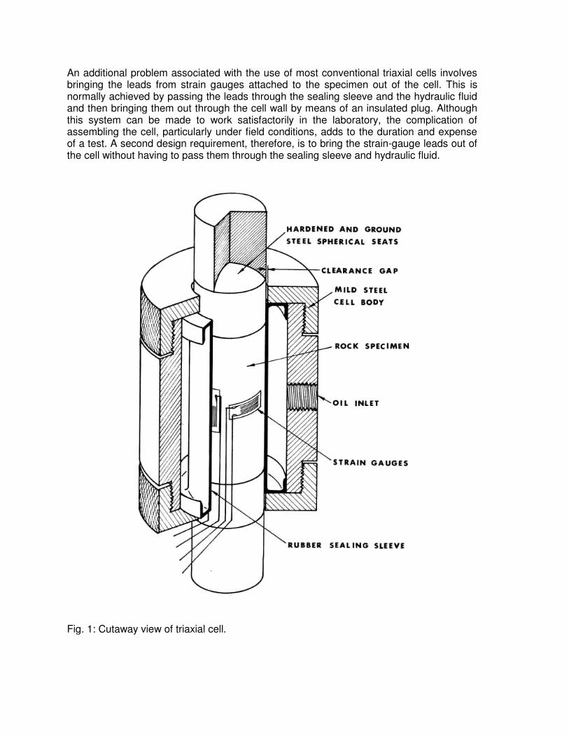
An additional problem associated with the use of most conventional triaxial cells involves bringing the leads from strain gauges attached to the specimen out of the cell. This is normally achieved by passing the leads through the sealing sleeve and the hydraulic fluid and then bringing them out through the cell wall by means of an insulated plug. Although this system can be made to work satisfactorily in the laboratory, the complication of assembling the cell, particularly under field conditions, adds to the duration and expense of a test. A second design requirement, therefore, is to bring the strain-gauge leads out of the cell without having to pass them through the sealing sleeve and hydraulic fluid.
Fig. 1: Cutaway view of triaxial cell.

Other design requirements, for example the accuracy of load measurement and the elimination of bending in the specimen, are common to all materials testing procedures and do not require detailed discussion here. The above requirements should be embodied in a cell which is capable of confining pressures of at least 10 000 lbf/in2 (the order of magnitude of stresses often encountered in engineering rock mechanics problems) and is, at the same time, portable and reliable.
Design solution
The design evolved to satisfy the requirements listed above is illustrated in Fig. 1. A rubber sleeve with integral U-shaped seals at either end is retained inside a steel cylinder by means of two threaded end caps. Oil is contained in the annular space between the sleeve and the cylinder and it is possible to slide the specimen, platens and strain-gauge leads into the cell, and to test and remove the specimen without breaking the seal. In order to present a clear picture of the design and operation of the triaxial cell, each element of the apparatus is discussed separately.
Steel cell body
The cell body has to be designed to withstand an internal hydraulic pressure of 10 000 lbf/in2. In choosing a material for this application care must be taken to avoid a steel which exhibits a tendency to fracture in a brittle manner since any crack initiating at a point of stress concentration would result in catastrophic failure of the cell. A material with good elongation and impact properties, such as ordinary mild steel, or an alloy steel in an annealed state, is ideal for containing pressures of up to 10 000 lbf/in2. Since no one dimension of this particular design is critical, a reasonable amount of plastic deformation at points of high stress concentration can be tolerated. In the prototype cell, which has been tested up to 12 000 lbf/in2, mild steel has been found a perfectly adequate material for the cell body. If higher pressures are contemplated an easily machinable alloy steel, such as EN 25, is recommended. Plating or painting the outer surface of the cell body is desirable in order to prevent rusting in field applications. End caps, screwed on to the cylindrical cell body as illustrated in Fig. 1, are provided in order to facilitate assembly of the cell and the removal of severely deformed specimens. Two quick-release self-sealing Simplex hydraulic couplings are screwed into the cell to provide for circulation of the hydraulic fluid and for the coupling of a pressure transducer.
Rubber sleeve
The rubber sealing sleeve is undoubtedly the most critical element in this apparatus as it has to continue to act as an effective seal even when the rock specimen has been extensively fractured or deformed. The design of the rubber sleeve must be considered in conjunction with the choice of the clearance gap between the loading platens and the end cap holes. To minimize the possibility of metal-metal contact and to facilitate the bringing out of strain-gauge leads this clearance gap should be as large as possible. On the other hand, extrusion of the
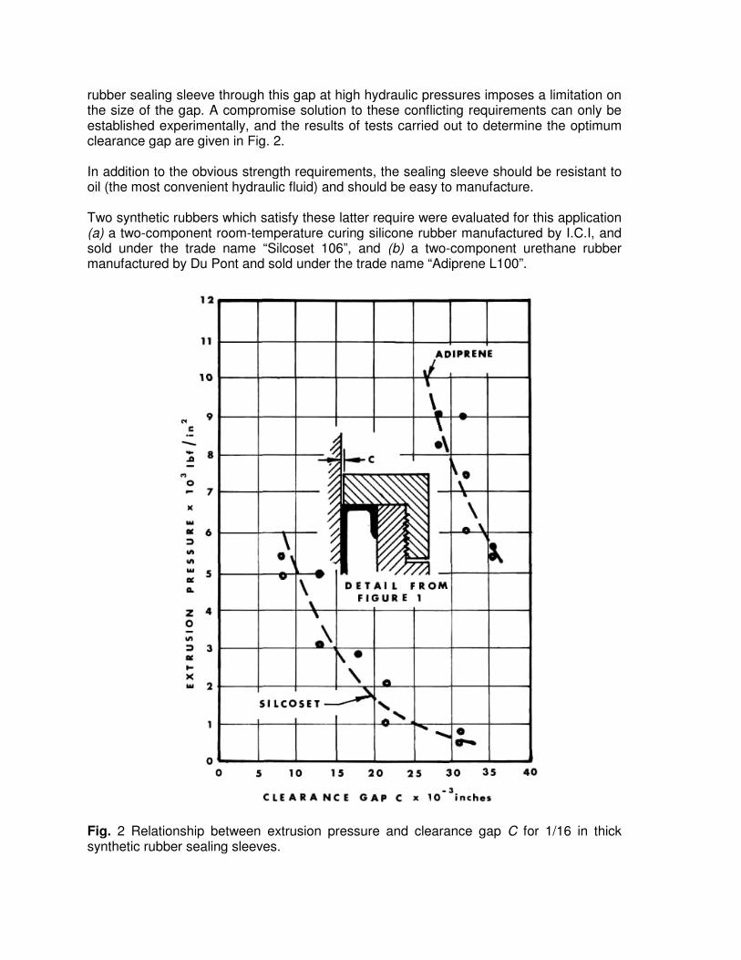
rubber sealing sleeve through this gap at high hydraulic pressures imposes a limitation on the size of the gap. A compromise solution to these conflicting requirements can only be established experimentally, and the results of tests carried out to determine the optimum clearance gap are given in Fig. 2. In addition to the obvious strength requirements, the sealing sleeve should be resistant to oil (the most convenient hydraulic fluid) and should be easy to manufacture. Two synthetic rubbers which satisfy these latter require were evaluated for this application (a) a two-component room-temperature curing silicone rubber manufactured by I.C.I, and sold under the trade name “Silcoset 106”, and (b) a two-component urethane rubber manufactured by Du Pont and sold under the trade name “Adiprene L100”. Fig. 2 Relationship between extrusion pressure and clearance gap C for 1/16 in thick synthetic rubber sealing sleeves.
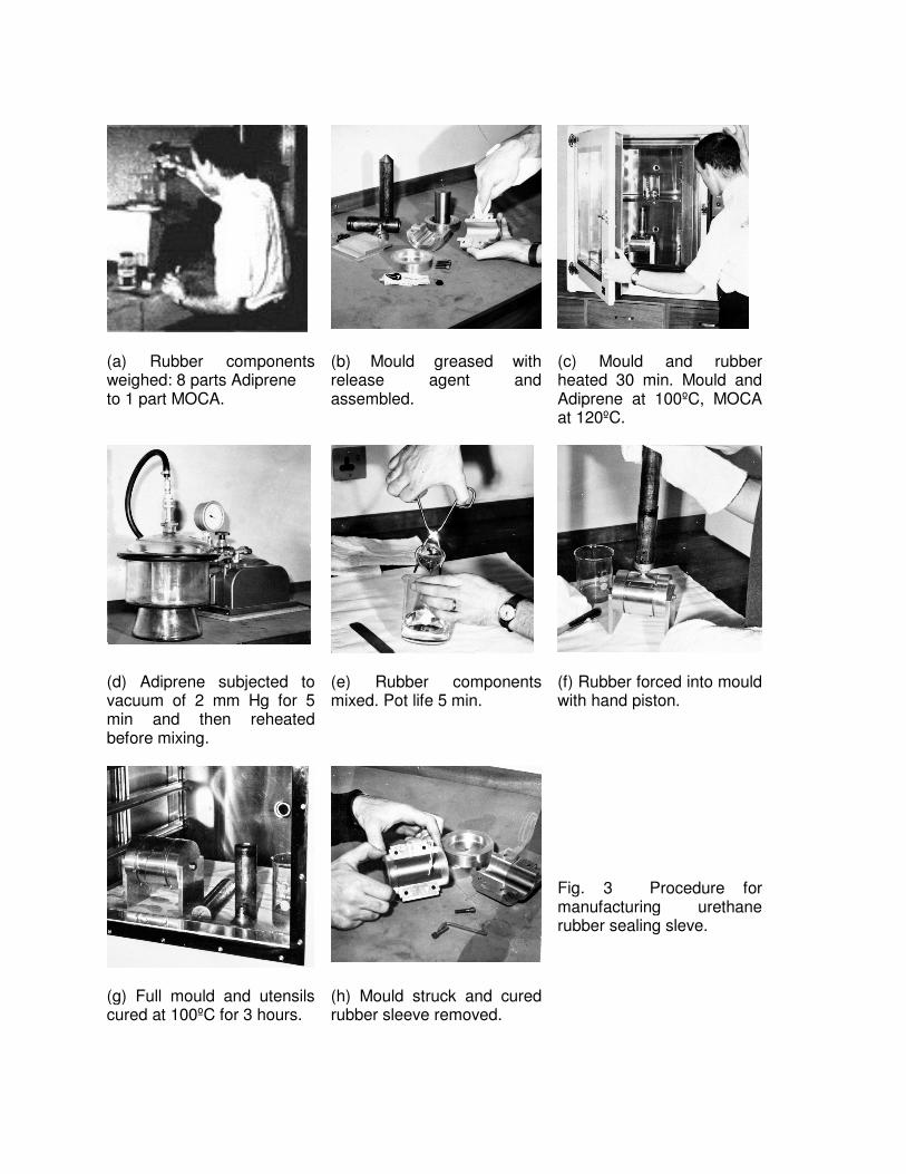
(a) Rubber components weighed: 8 parts Adiprene to 1 part MOCA.
(b) Mould greased with release agent and assembled.
(c) Mould and rubber heated 30 min. Mould and Adiprene at 100ºC, MOCA at 120ºC.
(d) Adiprene subjected to vacuum of 2 mm Hg for 5 min and then reheated before mixing.
(e) Rubber components mixed. Pot life 5 min.
(f) Rubber forced into mould with hand piston.
Fig. 3 Procedure for manufacturing urethane rubber sealing sleve.
(g) Full mould and utensils cured at 100ºC for 3 hours.
(h) Mould struck and cured rubber sleeve removed.
The steps in manufacturing a urethane rubber sealing sleeve are illustrated in Fig. 3. The procedure for casting silicone rubber is similar, except that the heating is not necessary and the curing takes 24 hours at room temperature. A detailed discussion on the properties and casting procedures for these two rubbers is given in the Appendix. Fig. 2 shows that, while the 1/16 in thick Silcoset silicone rubber sleeves are suitable for low-pressure triaxial testing, testing at confining pressures of up to 10 000 lbf/in2 requires the use of the Adiprene urethane rubber sleeves. Several tests on these Adiprene sleeves showed that, provided the clearance gap, C, is kept below 20x10-3 in (i.e. the difference in diameter between the end cap hole and the platen is less than 40 x 10-3 in), the sleeve will withstand pressures of up to 12 000 lbf/in2 without exhibiting any signs of permanent damage. Indeed, experience gained in testing hard and abrasive rocks such as granite and sandstone has shown that the Adiprene sleeves will withstand very severe treatment and can be reused a large number of times. Insulated wire of 10 to 15 x 10-3 in in diameter is readily available and is suitable for strain-gauge work. Consequently, a clearance gap of 15 to 20 x 10-3 in can be used in a triaxial cell, which is fitted with a 1/16 in thick urethane rubber sleeve, at confining pressures of up to 10 000 lbf/in2. In order to ensure that the rubber sleeve seals at zero hydraulic pressure, the outer diameter of the U-shaped end of the sleeve is made slightly larger than the inner diameter of the steel cell body. During assembly the rubber sleeve is inserted by compressing the outer lip of the U-seal and easing it into the bore of the cell as illustrated in Fig. 4(a). Once inserted, the U-seal springs outwards and seals off the oil space.
Spherical seats and platens
A detailed discussion on the stress distribution in a cylindrical compression specimen would exceed the scope of this paper. The interested reader is referred to a recent review by Jaeger2 in which the influence of the specimen shape and platen effects on the stress distribution was discussed. Theoretical and experimental studies3 have shown that reliable test results can be obtained from compressive tests on cylindrical rock specimens provided that (a) the length to diameter ratio of the specimen is at least 2, (b) bending in the specimen is minimized and (c) care is taken to minimize the restraining influence of the steel platens on the specimen ends. Many rock mechanics workers seek to minimize bending in the specimen by specifying that the ends of the specimen should be both flat and parallel to each other. Since this latter requirement adds significantly to the time and expense of specimen preparation, particularly if this has to be carried out in the field,4 the authors prefer to use spherical seats at either end of the specimen to minimize bending. This means that the specimen ends must be ground flat but need not be parallel. The spherical seats are machined so that the centre of the sphere is located at the centre of the platen-rock interface. These seats are used without lubrication so that, once under load, they are effectively locked into position. Their sole function is to compensate for the initial misalignment of the specimen ends. The spherical seats can be manufactured from any good-quality tool steel which can be hardened and tempered to 60 Rockwell C before grinding and lapping.
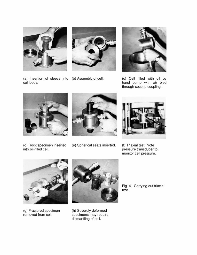
(a) Insertion of sleeve into cell body.
(b) Assembly of cell.
(c) Cell filled with oil by hand pump with air bled through second coupling.
(d) Rock specimen inserted into oil-filled cell.
(e) Spherical seats inserted.
(f) Triaxial test (Note pressure transducer to monitor cell pressure.
Fig. 4 Carrying out triaxial test.
(g) Fractured specimen removed from cell.
(h) Severely deformed specimens may require dismantling of cell.
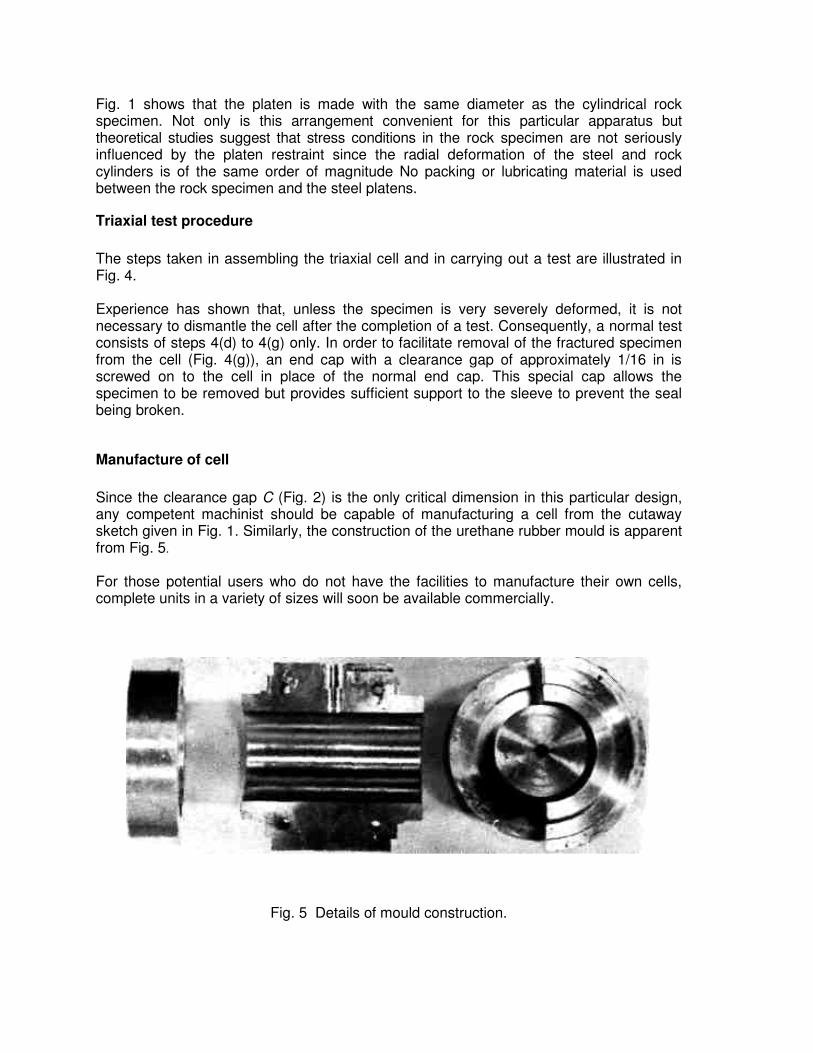
Fig. 1 shows that the platen is made with the same diameter as the cylindrical rock specimen. Not only is this arrangement convenient for this particular apparatus but theoretical studies suggest that stress conditions in the rock specimen are not seriously influenced by the platen restraint since the radial deformation of the steel and rock cylinders is of the same order of magnitude No packing or lubricating material is used between the rock specimen and the steel platens.
Triaxial test procedure
The steps taken in assembling the triaxial cell and in carrying out a test are illustrated in Fig. 4. Experience has shown that, unless the specimen is very severely deformed, it is not necessary to dismantle the cell after the completion of a test. Consequently, a normal test consists of steps 4(d) to 4(g) only. In order to facilitate removal of the fractured specimen from the cell (Fig. 4(g)), an end cap with a clearance gap of approximately 1/16 in is screwed on to the cell in place of the normal end cap. This special cap allows the specimen to be removed but provides sufficient support to the sleeve to prevent the seal being broken.
Manufacture of cell
Since the clearance gap C (Fig. 2) is the only critical dimension in this particular design, any competent machinist should be capable of manufacturing a cell from the cutaway sketch given in Fig. 1. Similarly, the construction of the urethane rubber mould is apparent from Fig. 5.
For those potential users who do not have the facilities to manufacture their own cells, complete units in a variety of sizes will soon be available commercially.
Fig. 5 Details of mould construction.
Acknowledgement
The authors wish to acknowledge the assistance of Mr. J. D. Sullivan, who was responsible for manufacturing the prototype cell and for carrying out the many modifications necessary in the development of the equipment described in this paper.
References
1. Obert L A. An inexpensive triaxial apparatus for testing mine rock. Rep. Invest. U.S. Bur. Mines 6332 1963, 10 p. 2. Jaeger J. C. Brittle fracture of rocks. In Failure and breakage of rock. Fairhurst C. ed. (New York: AIME, 1967). 3-57. 3. Hoek E. Rock fracture under static stress conditions. Ph.D. thesis. University of Cape Town, 1965. 4. Hoek E. Rock mechanics—an introduction for the practical engineer. Min. Mag., London, 114, 1966, 236-55,392-411:115, 1966, 4-15.
Appendix The manufacture of synthetic rubber sleeves for triaxial testing
A rubber was required that had a high strength and at the same time was moderately flexible, showed little tendency to creep, and was easy to cast. Two types of rubber were given detailed investigation. The first was a silicone rubber, marketed by I.C.I, under the trade name 'Silcoset'; the second was a urethane rubber marketed by Du Pont under the trade name of "Adiprene L100'.
Comparison of mechanical properties
Natural rubber has a tensile strength of about 3000 lb/in2, whereas Silcoset 106 silicone rubber has a tensile strength of 850 lb/in2 ' and Adiprene urethane rubber has a strength of over 4500 lb/in2. The Silcoset rubber is extremely flexible, having a durometer A hardness of 60, and the Adiprene rubber is stiffer, having a durometer hardness of 90, compared with the hardness of natural rubber, which varies between 30 and 90.
Mixing and casting procedure for silicone rubber
Of the various Silcoset rubbers, Silcoset 106 was chosen as being the strongest. It is a readily pourable red liquid that is cured by mixing with 1 per cent by weight of curing agent type A. 200 g of rubber were found to be sufficient for the average size sleeve. To this 2 g of the liquid curing agent were added and the contents were stirred for not less than 3 min and then deaered in a vacuum of less than 2 torr (2 mm of mercury) for not less than 5 min. The mixing bowl should have a depth at least equal to twice the depth of the rubber to avoid boiling over during the evacuation process. The mixture has a pot life of about 15 min. The rubber is then carefully poured or injected into the mould and left standing at room temperature for 24 hours, after which the mould can be struck. The rubber casting will gain strength slightly over a period of two or three days.
Procedure for mixing and casting urethane rubber
Either Diamine or Polyol curing agents may be used with Adiprene L100. The mix described below employs the diamine MOCA, producing a slightly stronger rubber. The Adiprene L100 in its raw state is just a liquid at room temperature (it freezes at 18°C). Freezing does not affect its properties, but it must be thoroughly mixed on melting, before use. The Adiprene L100 should not be heated for long above 49°C and it should not be subject to moisture. The MOCA curing agent is a granular solid at room temperature and melts at a temperature between 100 and 109°C. It is handled as a liquid at 121°C and must not be heated over 140°C. 200 g of Adiprene were found to be sufficient for the average size sleeve. The Adiprene, being extremely viscous at room temperature, entraps large quantities of air and was deaered before mixing with curing agent by heating to 100°C for 15 min and subjecting to a vacuum of at least 2 torr (2 mm Hg) for a further 5 min. The resin was then reheated to 100°C. To this were added 25 g MOCA that had been melted by heating at 120°C for approximately 30 min. The mixture was carefully but thoroughly stirred, avoiding as far as possible the introduction of air bubbles. The mixture had a pot life of about 5 min. The rubber was then carefully poured or injected into the mould, this having been preheated to 100°C and the mould and all soiled utensils were then placed in the oven to cure for 3 hours at 100°C, after which the mould could be struck and superfluous rubber peeled off the utensils. Flashing was trimmed off the rubber sleeve with a sharp razor blade.
Notes on mixing utensils
Pyrex beakers of 600-ml capacity were used to hold both silicone and urethane rubbers, and of 50-ml capacity for the MOCA curing agent. The utensils must be clean to avoid introducing air bubbles or small quantities of water. Flexible basins are preferable as containers for the rubbers since they are easier to clean after use but if, as with the urethane rubbers, the containers must be heated to 100°C, it is necessary to choose a basin that does not soften appreciably at that temperature.
Notes on mould design
Moulds for urethane rubber castings should allow for 1 - 2 per cent linear shrinkage on cooling the cured rubber. Silicone rubber, on the other hand, is dimensionally stable, since it is cured at room temperature. Moulds may be manufactured from mild steel or from duralumin if a less robust mould can be tolerated. Perspex moulds may be used for room-temperature casting. It has been found preferable to extrude the rubber into the mould using a simple hand-piston device. The rubber is extruded into a runner and sufficient risers must be provided to avoid the trapping of air within the mould. The location of risers and the design of a mould that will strip easily to release the casting require careful thought and a certain amount of trial and error.