Embed Size (px)
Citation preview
se ofate-
d duemethodfiberessedhereberarlyis-arac-that
ay beypes
John C. Gardiner
Jeffrey A. Weisse-mail: [email protected]
Department of Bioengineering,The University of Utah,
50 South Central Campus Drive #2480,Salt Lake City, UT 84112
Simple Shear Testing ofParallel-Fibered Planar SoftTissuesThe simple shear test may provide unique information regarding the material responparallel-fibered soft tissues because it allows the elimination of the dominant fiber mrial response from the overall stresses. However, inhomogeneities in the strain fielto clamping and free edge effects have not been documented. The finite elementwas used to study finite simple shear of simulated ligament material parallel to thedirection. The effects of aspect ratio, clamping prestrain, and bulk modulus were assusing a transversely isotropic, hyperelastic material model. For certain geometries, twas a central area of uniform strain. An aspect ratio of 1:2 for the fiber to cross-fidirections provided the largest region of uniform strain. The deformation was neisochoric for all bulk moduli indicating this test may be useful for isolating solid vcoelasticity from interstitial flow effects. Results suggest this test can be used to chterize the matrix properties for the type of materials examined in this study, andplanar measurements will suffice to characterize the strain. The test configuration museful for the study of matrix, fiber-matrix, and fiber-fiber material response in other tof parallel-fibered transversely isotropic soft tissues.@DOI: 10.1115/1.1351891#
r
t
i
trg
n
is
T
u
tt
thathave
and
ionopicene-
ur-seor-ak-
ble.ndineite
re-that
re-ure-d-
testrdi-ns.
rsmi-rop-
liga-
tohear
i
1 IntroductionCollagenous soft tissues are subjected to complex th
dimensional deformations in vivo that may include tension, copression, and shear. The shear behavior affects load transfetween microstructural parts of the tissue. Accurate measuremof material coefficients that govern the shear behavior of softsue can improve the descriptive and predictive value of constive models. Quantification of the effects of disease or treatmon shear properties can provide insight into the relationshiptween different tissue components and continuum level shearhavior.
Finite simple shear is a homogeneous deformation consisprimarily of deviatoric strain. It is used as a canonical problemhighlight differences between infinitesimal and large strain theoand to compare the response of different constitutive models.deformation is applied in-plane to a relatively thin matersample~Fig. 1A!. If the material is transversely isotropic and thlocal fiber direction is aligned with the shear direction, there wnot be elongation along the fiber direction. This eliminatesnormally dominant fiber material behavior from the tissuesponse to simple shear, providing an ideal method to investimatrix properties, fiber-matrix, and fiber-fiber interactions. Thedata can augment tensile test data and help to identify an appriate form for the matrix stress-strain behavior. Unlike the infitesimal strain theory, finite simple shear cannot be maintainedshear stress alone~e.g.,@1#!. Normal stresses are needed to matain the normal strains at zero. In the absence of normal strethe tissue will experience some contraction through the thicknand along the in-plane directions as shear strain is applied.will result in an inhomogeneous strain field that cannot be pdicted without additional analysis.
Infinitesimal cyclic shear loading has allowed the effectsstrain rate and orientation to be quantified in biological soft tiss@2,3#. These studies applied infinitesimal strains as either simor torsional shears. In contrast, Wilson et al.@4# subjected rabbitmedial collateral ligament to inhomogeneous, large deformashear loading during uniaxial tests by making lateral incisions
Contributed by the Bioengineering Division for publication in the JOURNAL OFBIOMECHANICAL ENGINEERING. Manuscript received by the Bioengineering Divsion Jan. 2000; revised manuscript received Dec. 2000. Associate Editor: LSetton.
170 Õ Vol. 123, APRIL 2001 Copyright © 2
ee-m-r be-ent
tis-itu-entbe-be-
tingtory,Thealeillhee-atesepro-i-by
n-ses,esshis
re-
ofesple
ionhat
generated longitudinal shear planes. Results demonstratedligaments have a finite resistance to shear. Shear propertiesalso been investigated via tensile@5# or biaxial @6# tests with anoblique fiber direction. These techniques apply both sheartension.
The finite simple shear test could provide unique informatregarding the material response of planar, transversely isotrsoft tissues such as ligaments. However, strain field inhomogities in the experimental setting have never been quantified. Fther, it is unclear if out-of-plane strains will be significant in thetests. Nonuniform strain fields could extend into the central ption of the test specimen, polluting the measured strains and ming the assumption of a homogeneous deformation unreliaAlso, bulk properties could interact with clamping effects asample dimensions. The objectives of this study were to examfinite simple shear of simulated ligament material using the finelement~FE! method. The effects of aspect ratio, clamping pstrain, and bulk modulus were assessed. It was hypothesizedcomplete characterization of the deformation within a centralgion of the tissue could be obtained using only planar measments of strain, providing a protocol for future experimental stuies of soft tissue shear properties.
2 Materials and MethodsThe FE method was used to simulate a finite simple shear
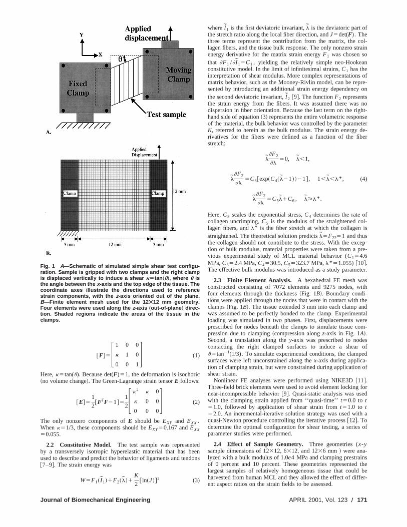
of a planar sample of transversely isotropic material. The coonate system in Fig. 1 is used throughout the following sectioInitial fiber direction was oriented along they-axis. This orienta-tion eliminates the fiber contribution—orientation of the fibealong thex-axis would result in the shear response being donated by the fiber stress. Specimen dimensions and material perties were chosen to represent the human medial collateralment ~MCL!.
2.1 Comparison to Theoretical Solution. The Green-Lagrange shear (EXY , EYZ , andEXZ) and normal strains (EXX ,EYY , andEZZ) predicted by the FE simulations were comparedexpected values for homogeneous simple shear. For simple sparallel to they-axis, the deformation gradientF can be deter-mined from the shear angleu between thex-axis and the top/bottom edges of the sample~Fig. 1A!:
-. A.
001 by ASME Transactions of the ASME
e
d
ol-train
n
s ofre-
y on
noht-
seterde-er
fl-is
ep-re-
ter.
swith
thendntalereom-
sof
ed
of
ford
h a
s of
sd the
beer-
@F#5F 1 0 0
k 1 0
0 0 1G (1)
Here,k5tan(u). Because det(F)51, the deformation is isochoric~no volume change!. The Green-Lagrange strain tensorE follows:
@E#51
2@FTF21#5
1
2F k2 k 0
k 0 0
0 0 0G (2)
The only nonzero components ofE should beEXY and EXX .Whenk51/3, these components should beEXY50.167 andEXX50.055.
2.2 Constitutive Model. The test sample was representby a transversely isotropic hyperelastic material that has bused to describe and predict the behavior of ligaments and ten@7–9#. The strain energy was
W5F1~ I 1!1F2~ l!1K
2@ ln~J!#2 (3)
Fig. 1 A—Schematic of simulated simple shear test configu-ration. Sample is gripped with two clamps and the right clampis displaced vertically to induce a shear kÄtan „u…, where u isthe angle between the x-axis and the top edge of the tissue. Thecoordinate axes illustrate the directions used to referencestrain components, with the z-axis oriented out of the plane.B—Finite element mesh used for the 12 Ã12 mm geometry.Four elements were used along the z-axis „out-of-plane … direc-tion. Shaded regions indicate the areas of the tissue in theclamps.
Journal of Biomechanical Engineering
deenons
whereI 1 is the first deviatoric invariant,l is the deviatoric part ofthe stretch ratio along the local fiber direction, andJ5det(F). Thethree terms represent the contribution from the matrix, the clagen fibers, and the tissue bulk response. The only nonzero senergy derivative for the matrix strain energyF1 was chosen sothat ]F1 /] I 15C1 , yielding the relatively simple neo-Hookeaconstitutive model. In the limit of infinitesimal strains,C1 has theinterpretation of shear modulus. More complex representationmatrix behavior, such as the Mooney-Rivlin model, can be repsented by introducing an additional strain energy dependencthe second deviatoric invariant,I 2 @9#. The functionF2 representsthe strain energy from the fibers. It was assumed there wasdispersion in fiber orientation. Because the last term on the righand side of equation~3! represents the entire volumetric responof the material, the bulk behavior was controlled by the parameK, referred to herein as the bulk modulus. The strain energyrivatives for the fibers were defined as a function of the fibstretch:
l]F2
]l50, l,1,
l]F2
]l5C3@exp~C4~ l21!!21#, 1,l,l* , (4)
l]F2
]l5C5l1C6 , l>l* .
Here,C3 scales the exponential stress,C4 determines the rate ocollagen uncrimping,C5 is the modulus of the straightened colagen fibers, andl* is the fiber stretch at which the collagenstraightened. The theoretical solution predictsl5F2251 and thusthe collagen should not contribute to the stress. With the exction of bulk modulus, material properties were taken from a pvious experimental study of MCL material behavior (C154.6MPa,C352.4 MPa,C4530.5,C55323.7 MPa,l* 51.055)@10#.The effective bulk modulus was introduced as a study parame
2.3 Finite Element Analysis. A hexahedral FE mesh waconstructed consisting of 7072 elements and 9275 nodes,four elements through the thickness~Fig. 1B!. Boundary condi-tions were applied through the nodes that were in contact withclamps~Fig. 1B!. The tissue extended 3 mm into each clamp awas assumed to be perfectly bonded to the clamp. Experimeloading was simulated in two phases. First, displacements wprescribed for nodes beneath the clamps to simulate tissue cpression due to clamping~compression alongz-axis in Fig. 1A!.Second, a translation along they-axis was prescribed to nodecontacting the right clamped surfaces to induce a shearu5tan21(1/3). To simulate experimental conditions, the clampsurfaces were left unconstrained along thex-axis during applica-tion of clamping strain, but were constrained during applicationshear strain.
Nonlinear FE analyses were performed using NIKE3D@11#.Three-field brick elements were used to avoid element lockingnear-incompressible behavior@9#. Quasi-static analysis was usewith the clamping strain applied from ‘‘quasi-time’’t50.0 to t51.0, followed by application of shear strain fromt51.0 to t52.0. An incremental-iterative solution strategy was used witquasi-Newton procedure controlling the iterative process@12#. Todetermine the optimal configuration for shear testing, a serieparameter studies were performed.
2.4 Effect of Sample Geometry. Three geometries (x-ysample dimensions of 12312, 6312, and 1236 mm ! were ana-lyzed with a bulk modulus of 1.0e4 MPa and clamping prestrainof 0 percent and 10 percent. These geometries representelargest samples of relatively homogeneous tissue that couldharvested from human MCL and they allowed the effect of diffent aspect ratios on the strain fields to be assessed.
APRIL 2001, Vol. 123 Õ 171
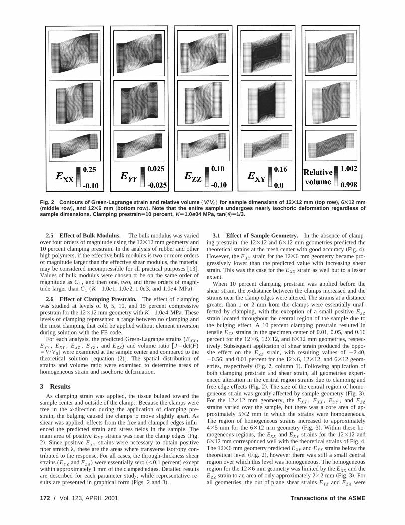
Fig. 2 Contours of Green-Lagrange strain and relative volume „VÕV0… for sample dimensions of 12 Ã12 mm „top row …, 6Ã12 mm„middle row …, and 12Ã6 mm „bottom row …. Note that the entire sample undergoes nearly isochoric deformation regardless ofsample dimensions. Clamping prestrain Ä10 percent, KÄ1.0e04 MPa, tan „u…Ä1Õ3.
t
e
n
s
s
n
vc
ue
-e
-earr
thethetanceaf-
e toin
.16-po-
eri-and-
f ap-s.tely
. 4.
lous
2.5 Effect of Bulk Modulus. The bulk modulus was variedover four orders of magnitude using the 12312 mm geometry and10 percent clamping prestrain. In the analysis of rubber and ohigh polymers, if the effective bulk modulus is two or more ordeof magnitude larger than the effective shear modulus, the matmay be considered incompressible for all practical purposes@13#.Values of bulk modulus were chosen to be on the same ordemagnitude asC1 , and then one, two, and three orders of magtude larger thanC1 (K51.0e1, 1.0e2, 1.0e3, and 1.0e4 MPa!.
2.6 Effect of Clamping Prestrain. The effect of clampingwas studied at levels of 0, 5, 10, and 15 percent compresprestrain for the 12312 mm geometry withK51.0e4 MPa. Theselevels of clamping represented a range between no clampingthe most clamping that cold be applied without element inversduring solution with the FE code.
For each analysis, the predicted Green-Lagrange strains (EXX ,EYY , EXY , EXZ , EYZ , and EZZ) and volume ratio@J5det(F)5V/V0# were examined at the sample center and compared totheoretical solution@equation ~2!#. The spatial distribution ofstrains and volume ratio were examined to determine areahomogeneous strain and isochoric deformation.
3 ResultsAs clamping strain was applied, the tissue bulged toward
sample center and outside of the clamps. Because the clampsfree in the x-direction during the application of clamping prestrain, the bulging caused the clamps to move slightly apart.shear was applied, effects from the free and clamped edges ienced the predicted strain and stress fields in the sample.main area of positiveEYY strains was near the clamp edges~Fig.2!. Since positiveEYY strains were necessary to obtain positifiber stretchl, these are the areas where transverse isotropytributed to the response. For all cases, the through-thickness sstrains (EYZ andEZX) were essentially zero~,0.1 percent! exceptwithin approximately 1 mm of the clamped edges. Detailed resare described for each parameter study, while representativsults are presented in graphical form~Figs. 2 and 3!.
172 Õ Vol. 123, APRIL 2001
herrsrial
r ofi-
ive
andion
the
of
thewere-Asflu-The
eon-hear
ltsre-
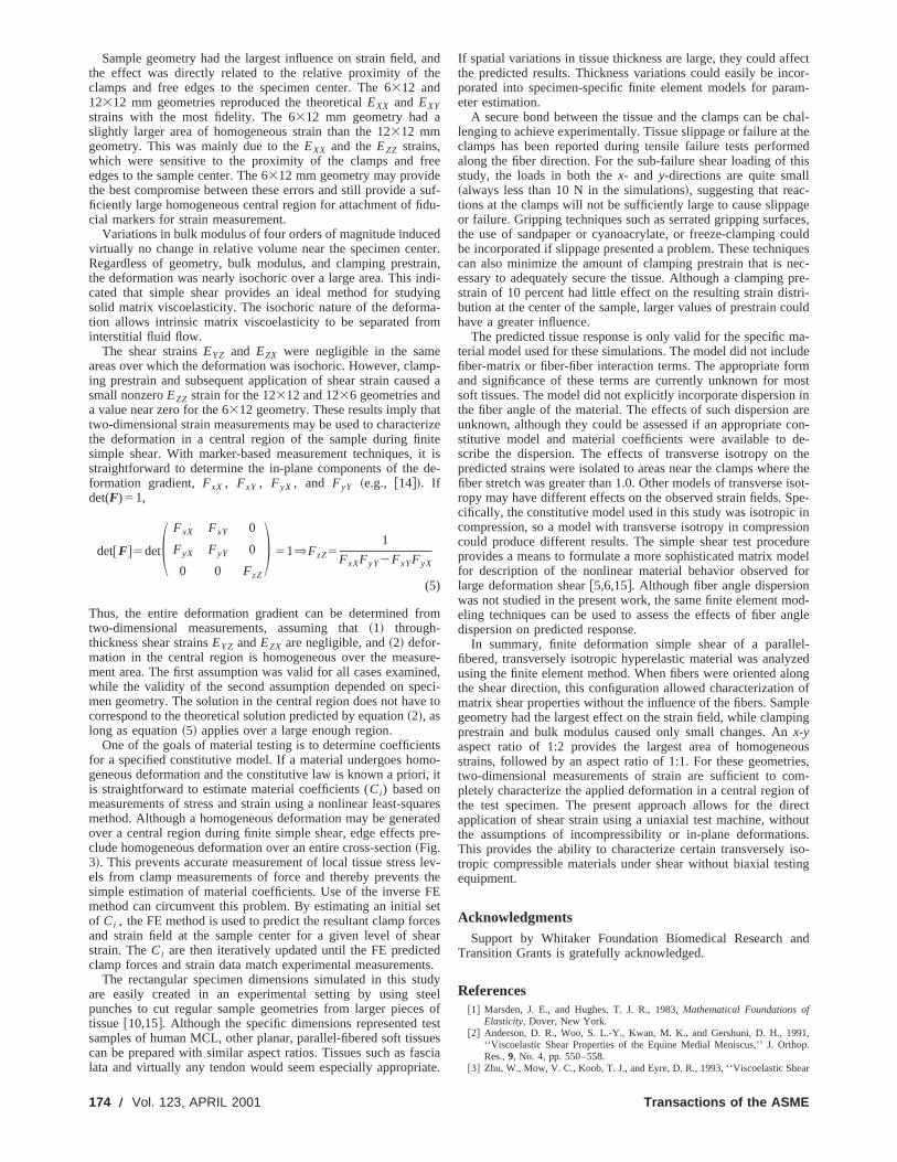
3.1 Effect of Sample Geometry. In the absence of clamping prestrain, the 12312 and 6312 mm geometries predicted ththeoretical strains at the mesh center with good accuracy~Fig. 4!.However, theEXY strain for the 1236 mm geometry became progressively lower than the predicted value with increasing shstrain. This was the case for theEXX strain as well but to a lesseextent.
When 10 percent clamping prestrain was applied beforeshear strain, thex-distance between the clamps increased andstrains near the clamp edges were altered. The strains at a disgreater than 1 or 2 mm from the clamps were essentially unfected by clamping, with the exception of a small positiveEZZstrain located throughout the central region of the sample duthe bulging effect. A 10 percent clamping prestrain resultedtensileEZZ strains in the specimen center of 0.01, 0.05, and 0percent for the 1236, 12312, and 6312 mm geometries, respectively. Subsequent application of shear strain produced the opsite effect on theEZZ strain, with resulting values of22.40,20.56, and 0.01 percent for the 1236, 12312, and 6312 geom-etries, respectively~Fig. 2, column 1!. Following application ofboth clamping prestrain and shear strain, all geometries expenced alteration in the central region strains due to clampingfree edge effects~Fig. 2!. The size of the central region of homogeneous strain was greatly affected by sample geometry~Fig. 3!.For the 12312 mm geometry, theEXY , EXX , EYY , and EZZstrains varied over the sample, but there was a core area oproximately 532 mm in which the strains were homogeneouThe region of homogeneous strains increased to approxima435 mm for the 6312 mm geometry~Fig. 3!. Within these ho-mogeneous regions, theEXX and EXY strains for the 12312 and6312 mm corresponded well with the theoretical strains of FigThe 1236 mm geometry predictedEXY andEXX strains below thetheoretical level~Fig. 2!, however there was still a small centraregion over which this level was homogeneous. The homogeneregion for the 1236 mm geometry was limited by theEXX and theEZZ strain to an area of only approximately 232 mm ~Fig. 3!. Forall geometries, the out of plane shear strainsEYZ and EZX were
Transactions of the ASME
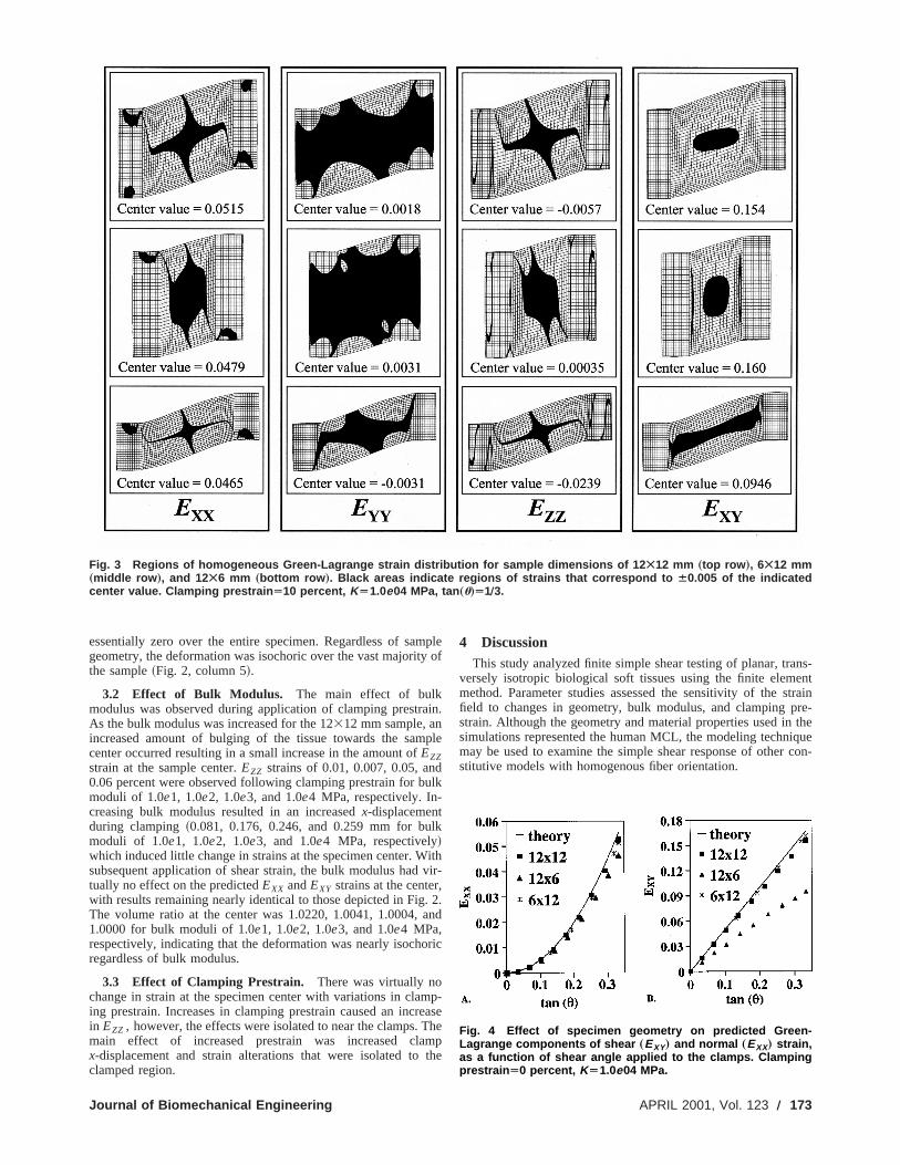
Fig. 3 Regions of homogeneous Green-Lagrange strain distribution for sample dimensions of 12 Ã12 mm „top row …, 6Ã12 mm„middle row …, and 12Ã6 mm „bottom row …. Black areas indicate regions of strains that correspond to Á0.005 of the indicatedcenter value. Clamping prestrain Ä10 percent, KÄ1.0e04 MPa, tan „u…Ä1Õ3.
m
a
du
l
,.
meT
ns-nttrainre-thequecon-
essentially zero over the entire specimen. Regardless of sageometry, the deformation was isochoric over the vast majoritythe sample~Fig. 2, column 5!.
3.2 Effect of Bulk Modulus. The main effect of bulkmodulus was observed during application of clamping prestrAs the bulk modulus was increased for the 12312 mm sample, anincreased amount of bulging of the tissue towards the samcenter occurred resulting in a small increase in the amount ofEZZstrain at the sample center.EZZ strains of 0.01, 0.007, 0.05, an0.06 percent were observed following clamping prestrain for bmoduli of 1.0e1, 1.0e2, 1.0e3, and 1.0e4 MPa, respectively. In-creasing bulk modulus resulted in an increasedx-displacementduring clamping~0.081, 0.176, 0.246, and 0.259 mm for bumoduli of 1.0e1, 1.0e2, 1.0e3, and 1.0e4 MPa, respectively!which induced little change in strains at the specimen center. Wsubsequent application of shear strain, the bulk modulus hadtually no effect on the predictedEXX andEXY strains at the centerwith results remaining nearly identical to those depicted in FigThe volume ratio at the center was 1.0220, 1.0041, 1.0004,1.0000 for bulk moduli of 1.0e1, 1.0e2, 1.0e3, and 1.0e4 MPa,respectively, indicating that the deformation was nearly isochoregardless of bulk modulus.
3.3 Effect of Clamping Prestrain. There was virtually nochange in strain at the specimen center with variations in claing prestrain. Increases in clamping prestrain caused an incrin EZZ , however, the effects were isolated to near the clamps.main effect of increased prestrain was increased clax-displacement and strain alterations that were isolated toclamped region.
Journal of Biomechanical Engineering
pleof
in.
ple
lk
k
ithvir-
2.and
ric
p-asehe
mpthe
4 DiscussionThis study analyzed finite simple shear testing of planar, tra
versely isotropic biological soft tissues using the finite elememethod. Parameter studies assessed the sensitivity of the sfield to changes in geometry, bulk modulus, and clamping pstrain. Although the geometry and material properties used insimulations represented the human MCL, the modeling technimay be used to examine the simple shear response of otherstitutive models with homogenous fiber orientation.
Fig. 4 Effect of specimen geometry on predicted Green-Lagrange components of shear „EXY… and normal „EXX… strain,as a function of shear angle applied to the clamps. Clampingprestrain Ä0 percent, KÄ1.0e04 MPa.
APRIL 2001, Vol. 123 Õ 173
h
d
e
ny
m
a
r
n
i
p
s
e
e
aa
fectcor-am-
chal-themedhisl-geces,ouldquesec-pre-tri-uld
a-de
rmostinarecon-de-the
e theisot-pe-in
sionure
odelfor
od-ngle
el-zedong
ofpleing
ousies,m-of
irectoutns.iso-ting
nd
1,op.
ar
Sample geometry had the largest influence on strain field,the effect was directly related to the relative proximity of tclamps and free edges to the specimen center. The 6312 and12312 mm geometries reproduced the theoreticalEXX and EXYstrains with the most fidelity. The 6312 mm geometry had aslightly larger area of homogeneous strain than the 12312 mmgeometry. This was mainly due to theEXX and theEZZ strains,which were sensitive to the proximity of the clamps and fredges to the sample center. The 6312 mm geometry may providethe best compromise between these errors and still provide aficiently large homogeneous central region for attachment of ficial markers for strain measurement.
Variations in bulk modulus of four orders of magnitude inducvirtually no change in relative volume near the specimen cenRegardless of geometry, bulk modulus, and clamping prestrthe deformation was nearly isochoric over a large area. This icated that simple shear provides an ideal method for studsolid matrix viscoelasticity. The isochoric nature of the deformtion allows intrinsic matrix viscoelasticity to be separated frointerstitial fluid flow.
The shear strainsEYZ and EZX were negligible in the sameareas over which the deformation was isochoric. However, claing prestrain and subsequent application of shear strain caussmall nonzeroEZZ strain for the 12312 and 1236 geometries anda value near zero for the 6312 geometry. These results imply thtwo-dimensional strain measurements may be used to charactthe deformation in a central region of the sample during finsimple shear. With marker-based measurement techniques,straightforward to determine the in-plane components of theformation gradient,FxX , FxY , FyX , and FyY ~e.g., @14#!. Ifdet(F)51,
det@F#5detS FxX FxY 0
FyX FyY 0
0 0 FzZ
D 51⇒FzZ51
FxXFyY2FxYFyX
(5)
Thus, the entire deformation gradient can be determined ftwo-dimensional measurements, assuming that~1! through-thickness shear strainsEYZ andEZX are negligible, and~2! defor-mation in the central region is homogeneous over the measment area. The first assumption was valid for all cases examiwhile the validity of the second assumption depended on spmen geometry. The solution in the central region does not havcorrespond to the theoretical solution predicted by equation~2!, aslong as equation~5! applies over a large enough region.
One of the goals of material testing is to determine coefficiefor a specified constitutive model. If a material undergoes homgeneous deformation and the constitutive law is known a prioris straightforward to estimate material coefficients (Ci) based onmeasurements of stress and strain using a nonlinear least-sqmethod. Although a homogeneous deformation may be generover a central region during finite simple shear, edge effectsclude homogeneous deformation over an entire cross-section~Fig.3!. This prevents accurate measurement of local tissue stressels from clamp measurements of force and thereby preventssimple estimation of material coefficients. Use of the inversemethod can circumvent this problem. By estimating an initialof Ci , the FE method is used to predict the resultant clamp forand strain field at the sample center for a given level of shstrain. TheCi are then iteratively updated until the FE predictclamp forces and strain data match experimental measureme
The rectangular specimen dimensions simulated in this stare easily created in an experimental setting by using spunches to cut regular sample geometries from larger piecetissue@10,15#. Although the specific dimensions represented tsamples of human MCL, other planar, parallel-fibered soft tisscan be prepared with similar aspect ratios. Tissues such as flata and virtually any tendon would seem especially appropri
174 Õ Vol. 123, APRIL 2001
ande
ee
suf-u-
dter.ain,di-inga-m
p-ed a
terizeiteit isde-
om
ure-ed,
eci-e to
ntso-
, it
uaresatedre-
lev-the
FEet
ceseard
nts.udyteels ofst
uessciate.
If spatial variations in tissue thickness are large, they could afthe predicted results. Thickness variations could easily be inporated into specimen-specific finite element models for pareter estimation.
A secure bond between the tissue and the clamps can belenging to achieve experimentally. Tissue slippage or failure atclamps has been reported during tensile failure tests perforalong the fiber direction. For the sub-failure shear loading of tstudy, the loads in both thex- and y-directions are quite smal~always less than 10 N in the simulations!, suggesting that reactions at the clamps will not be sufficiently large to cause slippaor failure. Gripping techniques such as serrated gripping surfathe use of sandpaper or cyanoacrylate, or freeze-clamping cbe incorporated if slippage presented a problem. These technican also minimize the amount of clamping prestrain that is nessary to adequately secure the tissue. Although a clampingstrain of 10 percent had little effect on the resulting strain disbution at the center of the sample, larger values of prestrain cohave a greater influence.
The predicted tissue response is only valid for the specific mterial model used for these simulations. The model did not inclufiber-matrix or fiber-fiber interaction terms. The appropriate foand significance of these terms are currently unknown for msoft tissues. The model did not explicitly incorporate dispersionthe fiber angle of the material. The effects of such dispersionunknown, although they could be assessed if an appropriatestitutive model and material coefficients were available toscribe the dispersion. The effects of transverse isotropy onpredicted strains were isolated to areas near the clamps wherfiber stretch was greater than 1.0. Other models of transverseropy may have different effects on the observed strain fields. Scifically, the constitutive model used in this study was isotropiccompression, so a model with transverse isotropy in comprescould produce different results. The simple shear test procedprovides a means to formulate a more sophisticated matrix mfor description of the nonlinear material behavior observedlarge deformation shear@5,6,15#. Although fiber angle dispersionwas not studied in the present work, the same finite element meling techniques can be used to assess the effects of fiber adispersion on predicted response.
In summary, finite deformation simple shear of a parallfibered, transversely isotropic hyperelastic material was analyusing the finite element method. When fibers were oriented althe shear direction, this configuration allowed characterizationmatrix shear properties without the influence of the fibers. Samgeometry had the largest effect on the strain field, while clampprestrain and bulk modulus caused only small changes. Anx-yaspect ratio of 1:2 provides the largest area of homogenestrains, followed by an aspect ratio of 1:1. For these geometrtwo-dimensional measurements of strain are sufficient to copletely characterize the applied deformation in a central regionthe test specimen. The present approach allows for the dapplication of shear strain using a uniaxial test machine, withthe assumptions of incompressibility or in-plane deformatioThis provides the ability to characterize certain transverselytropic compressible materials under shear without biaxial tesequipment.
AcknowledgmentsSupport by Whitaker Foundation Biomedical Research a
Transition Grants is gratefully acknowledged.
References@1# Marsden, J. E., and Hughes, T. J. R., 1983,Mathematical Foundations of
Elasticity,Dover, New York.@2# Anderson, D. R., Woo, S. L.-Y., Kwan, M. K., and Gershuni, D. H., 199
‘‘Viscoelastic Shear Properties of the Equine Medial Meniscus,’’ J. OrthRes.,9, No. 4, pp. 550–558.
@3# Zhu, W., Mow, V. C., Koob, T. J., and Eyre, D. R., 1993, ‘‘Viscoelastic She
Transactions of the ASME

t
N
a
ti
l
m-
an
-c-e-
ent
of
hear
Properties of Articular Cartilage and the Effects of Glycosidase TreatmenJ. Orthop. Res.,11, pp. 771–781.
@4# Wilson, A., Shelton, F., Chaput, C., Frank, C., Butler, D., and Shrive,1997, ‘‘The Shear Behavior of the Rabbit Medial Collateral Ligament,’’ MeEng. Phys.,19, No. 7, pp. 652–657.
@5# Goertzen, D. J., Budney, D. R., and Cinats, J. G., 1997, ‘‘MethodologyApparatus to Determine Material Properties of the Knee Joint MeniscuMed. Eng. Phys.,19, No. 5, pp. 412–419.
@6# Sacks, M. S., 1999, ‘‘A Method for Planar Biaxial Mechanical Testing ThIncludes In-Plane Shear,’’ ASME J. Biomech. Eng.,121, pp. 551–555.
@7# Puso, M. A., and Weiss, J. A., 1998, ‘‘Finite Element ImplementationAnisotropic Quasilinear Viscoelasticity,’’ ASME J. Biomech. Eng.,120, No.1, pp. 62–70.
@8# Weiss, J. A., 1994, ‘‘A Constitutive Model and Finite Element Representafor Transversely Isotropic Soft Tissues,’’ Ph.D. thesis, University of Utah, SLake City, UT.
@9# Weiss, J. A., Maker, B. N., and Govindjee, S., 1996, ‘‘Finite Element Imp
Journal of Biomechanical Engineering
s,’’
.,d.
nds,’’
at
of
onalt
e-
mentation of Incompressible, Transversely Isotropic Hyperelasticity,’’ Coput. Methods Appl. Mech. Eng.,135, pp. 107–128.
@10# Quapp, K. M., and Weiss, J. A., 1998, ‘‘Material Characterization of HumMedial Collateral Ligament,’’ ASME J. Biomech. Eng.,120, pp. 757–763.
@11# Maker, B. N., Ferencz, R. M., and Hallquist, J. O., 1990, ‘‘NIKE3D: A NonLinear, Implicit, Three-Dimensional Finite Element Code for Solid and Strutural Mechanics,’’ Lawrence Livermore National Laboratory Technical Rport, UCRL-MA-105268.
@12# Matthies, H., and Strang, G., 1979, ‘‘The Solution of Nonlinear Finite ElemEquations,’’ Int. J. Numer. Methods Eng.,14, pp. 1613–1626.
@13# Ogden, R. W., 1984,Nonlinear Elastic Deformations,Dover, New York.@14# Sacks, M., and Choung, C., 1998, ‘‘Orthotropic Mechanical Properties
Chemically Treated Bovine Pericardium,’’ Ann. Biomed. Eng.,26, pp. 892–902.
@15# Gardiner, J., Cordaro, N., and Weiss, J., 2000, ‘‘Elastic and Viscoelastic SProperties of the Medial Collateral Ligament,’’Trans 46th Annual Ortho-paedic Research Society Meeting,Vol. 25, p. 63.
APRIL 2001, Vol. 123 Õ 175