Embed Size (px)
Citation preview
SIMPLE & SECURE WI-FI CONFIGURATION FOR
INTERNET OF THINGS
Shujing Zhang
Electrical Engineering and Computer SciencesUniversity of California at Berkeley
Technical Report No. UCB/EECS-2013-86
http://www.eecs.berkeley.edu/Pubs/TechRpts/2013/EECS-2013-86.html
May 16, 2013

Copyright © 2013, by the author(s).All rights reserved.
Permission to make digital or hard copies of all or part of this work forpersonal or classroom use is granted without fee provided that copies arenot made or distributed for profit or commercial advantage and that copiesbear this notice and the full citation on the first page. To copy otherwise, torepublish, to post on servers or to redistribute to lists, requires prior specificpermission.


!
!!!!!!!
SIMPLE'&'SECURE'WI-FI'CONFIGURATION'FOR'INTERNET'OF'THINGS'By Shujing Zhang !!!!
A Thesis
Presented to the Department of Electrical Engineering and Computer
Science Graduate Division
of University of California, Berkeley
In Partial Fulfillment of the Requirements for the Degree of
Master of Engineering
April 2013
DO NOT CIRCULATE

i!
Abstract
This paper discusses a simple and secure way of enabling “Internet of Things” to be configured
with Wi-Fi PIN number and register it to the Internet. The Internet of Things are objects that are
embedded with sensors and actuators (from printers to pacemakers), and they are linked through
wired and wireless networks, often using the same Internet Protocol (IP) that connects the
Internet [1]. Many Internet of things do not have interactive interface, so we present a system
which requests information from physical objects by recording them and perform computer vision
techniques to extract the PIN number. After that, we can register them to the access point (AP)
through WPS (Wi-Fi Protected Setup) PIN based method protocol. The advantage of this project
is that the process saves people time to manually enter the PIN number into the router and there is
no password to remember.
In our model we aims at detecting the blinking pattern of red LED light using techniques in
computer vision. At the core of our system, we use camera on smartphones to facilitate the secure
Wi-Fi setup of these devices. First the camera records a video of LED light blinking, and then we
will analyze each of the video frames that are fetched from the smartphone SD card and decode
the blinking pattern into the binary numbers. After translating binary numbers into decimal
numbers, we can use the information to connect the device to the user Wi-Fi Access Point
through WPS protocol. The system allows simplest point-and-shoot interaction with objects. The
experiments evaluate the performance of our approach and show reliable results within short
distance. Future improvements on the robustness of the system should focus on invariance to the
distance and shaking, or changing smartphone’s hardware configurations.

ii!
!
!
Contents
Abstract i
1. Introduction ..................................................................................................................1
1.1 Internet of Things .....................................................................................................1
1.2 Computer Vision in Internet of Things ....................................................................2
2. Literature Review ........................................................................................................3
3. Methodology .................................................................................................................5
3.1 Detection of Flashing LED Light ............................................................................6
3.1.1 Preliminaries .................................................................................................6
3.1.2 Subtraction of Neighboring Frames ..............................................................6
3.1.3 Detect LED Switching ..................................................................................6
3.2 Decode the Light Pattern into 8-Digit PIN Number ................................................7
4. Results ...........................................................................................................................8
4.1 Unit Testing .............................................................................................................8
4.1.1 Query Frames from the Video ......................................................................8
4.1.2 Image Subtraction .........................................................................................9
4.1.3 Gray-Scale Image to Binary Image ...............................................................9
4.1.4 Light Switching ...........................................................................................10

! iii!
4.2 Overall Performance ..............................................................................................10
4.2.1 Accuracy and Robustness ..........................................................................10
4.2.2 Sensor Sensibility and Parameter Range ....................................................11
4.2.3 Different LED Lights ..................................................................................13
4.3 Minimal Processing Power and Memory Footprint ...............................................13
4.4 User Friendliness ...................................................................................................14
5. Discussion ...................................................................................................................15
5.1 Frame Rate Changes According to the Lighting Condition ..................................15
5.2 Detection of LED under Strong Light ...................................................................15
5.3 Android Native Camera Versus Media Recorder Object ......................................16
5.4 LED Light Switch Process .....................................................................................17
6. Recommendations ......................................................................................................18
6.1 Invariance to Distance ............................................................................................18
6.2 Object Detection ....................................................................................................18
6.3 Hardware Settings ..................................................................................................18
7. Conclusion ..................................................................................................................18

iv!
!
List of Figures 1.1 System overview .................................................................................................2
3.1 Overall procedure of the system .......................................................................6
3.2 Overall procedure of image processing ............................................................7
3.3 Sample digital signal pattern ............................................................................7
3.4 FMS for decoding process .................................................................................8
4.1 Data stream structure ........................................................................................9
4.2 LED before switching ........................................................................................9
4.3 LED after switching ...........................................................................................9
4.4 Image after subtraction ....................................................................................9
4.5 Gray scale image after subtraction ................................................................10
4.6 Gray scale image after thresholding ..............................................................10
4.7 Parameter Analysis under dim light scene ....................................................12
4.8 Parameter Analysis under sufficient light scene ...........................................12
4.9 Overall parameter analysis .............................................................................13
4.10 First interface of the application ..................................................................14
4.11 Second interface during recording .................................................................14
4.12 Result Interface ................................................................................................15
5.1 Picture record with MediaRecorder and with native camera .....................16
5.2 LED light switch process .................................................................................17
5.3 Two subtracted images from the states ..........................................................17

v!
!
List of Tables 4.1 Accuracy versus distance ..................................................................................11

! 1!
1. Introduction
Internet of things has become the new buzzword, expanding digital concept into the physical
world. From printers to lights bulbs, cars to appliances, they can all be connected to a single
network. The resulting networks promise to make personal lives easier, safer and more efficient.
1.1 Internet of Things
The Internet of Things (IoT) is a computing concept that describes a future where everyday
physical objects will be connected to the Internet and will be able to identify themselves to other
devices [2]. The significance about IoT is that it connects almost anything around it. By
extending the Internet to physical objects, various services can be available to interact with these
devices over the Internet such as query and change their state and any information associated with
them, taking into account security and privacy issues [3]. This vision promises human to live a
smart and highly connected life.
The first step to realize the vision is to connect the device to the Internet, which is the goal of our
project. Traditional way is to manually enter an 8-digits PIN number presented on the device into
the router, so that the PIN allows to perform mutual authentication between the device and the
Wi-Fi access point and subsequently download the Wi-Fi network credential to the device. Once
the device has the Wi-Fi network credential (WPA passphrase) it can connect to the access point
and is part of the user home network. Currently, most of the interaction involves having a unique
static marker attached to the object. Some simply use decimal numbers, some use visual tags like
barcodes, others use wireless near field communication (e.g. RFID). Our project involves getting
pairing information (e.g. PIN) from the physical objects, which is LED light in this case. The
light does not travel through walls and the user needs to be within direct sight and close distance
in order to configure the device. This adds to the advantage of the secure factor during the

! 2!
connection process. Figure 1.1 shows the overview of the LED light that sends out light patterns
for the smartphone to collect the signal.
Figure 1.1: The system consists of an Arduino board, a LED light and a smartphone. The
smartphone is going to record the LED blinking pattern and decode the pattern into 8-digit
PIN number.
1.2 Computer Vision in Internet of Things
Recent years sees the dramatic growth of smartphone industry. Smartphones have become
sophisticated yet handy processors that can be used to interact with various devices in the
environment. In addition, People are used to carry smartphones with them all day, so it is natural
to use smartphone as a media of registrar or Internet of things. The camera embedded in the
smartphone is a powerful sensor offering high quality pictures as well as high-speed scene
recording. However, under bad lighting conditions, it can deliver poor quality images with either
over or under-exposure. Usually smartphone manufacturers do not allow software developers to
alter low-level camera sensor hardware. Developers are only provided with APIs that performs
certain functions of the camera, hurting the performance of computer vision algorithms. As a
result, the subsequent techniques of processing the images are crucial to remedy the side effects
caused by hardware.

! 3!
A similar project is carried out at Maker Faire Bay Area in 2012 called Electric Imp, which is a
module containing an ARM Cortex M3SoC with embedded Wi-Fi that is built into an SD card
form factor. The company has developed Blinkup, a way to enter SSID and password information
on any iOS and Android smartphone and beam it to the Electric Imp’s light sensor by rapidly
pulsing the handset’s screen on and off [4]. Our project achieves similar results except that we
use the sensor on the smartphone to detect the light pattern.
In this paper, we present a method and system that relies on the advantage of Samsung Galaxy
SIII high-resolution camera to recognize the feature of the object, in our case, a LED light that
sends out blinking red signals in a specific pattern. We analyze the differences of light pattern
frame by frame and recognize the signal high and low. The analogue signal is then transformed to
binary digital code. Then the paper will discuss how android application is able to decode the
specific LED light pattern into PIN number. The rest of the paper will discuss the challenges that
we faced and future recommendations.
2. Literature Review
Our method can be related to other works in several aspects. One aspect covers work related to
our original method to detect the object, Object detection allows humans to link digital world to
the real physical world. Till Quack, Herbert Bay and Luc Van Gool present two applications for
object recognition, a slide tagging application for presentation screens in smart meeting rooms
and a city guide on a mobile phone, both of which are tested under application scenarios and
show good recognition result under challenging conditions [5]. The firs app is more related to our
project. The server side of which has a retrieval engine which indexes objects using scale
invariant visual features. Users can take a picture of an object, and then the picture is sent to the
server to retrieve the corresponding object. The system is completed with a client-side
application, which can be installed on a mobile handset. Their approach uses multiple view

! 4!
geometry to improve recognition, relying on SURF features (which are also more compact and
faster than SIFT features). However, we are not going to send the data to a server, instead, all the
processing procedure is going to be based solely on the smartphone.
The paper by Motilal Agrawal and Kurt Konolige discusses the state-of-the-art self-localization --
Augmented Reality (RA) based on computer vision [6]. Motilal Agrawal et al treat localization as
an image recognition problem. They describe a real-time, low-cost system to localize a mobile
robot in outdoor environment. The technic they use is stereovision to estimate frame-to-frame
motion in real time. A stereo pair will detect the feature point and track across frames. By using
stereo correspondences, they can triangulate each feature points at each frame. Three points will
be used to estimate the motion, and score them using the pixel re-projection errors. The
hypothesis with the best score is used as the starting point. Although, it is not so feasible for our
project to have two cameras recording at the same time, their idea of comparing the frame-to-
frame motion is quite useful in our project, in which way we can track the motion of an object by
analyzing the difference between two neighbor frames.
Another aspect is the image subtraction for neighboring frames. Akiko Kano, Kunio Doi, Heber
MacMahon, Dayne D. Hassell, and Maryellen L. Giger, who worked on analyzing chest images
for detection of interval change suggest an automated digital image subtraction technique for
temporally sequential chest images [7]. A local matching, based on a cross-correlation method, is
performed on each pair of corresponding region of interests in order to determine shift values for
the coordinates of two images. A proper warping of x, y coordinates is obtained by fitting two-
dimensional polynomials to the distributions of shift values. One of the images is warped and
then subtracted from the other. Akiko Kano et al’s method is most suitable in our project, and
turns out analyzing the difference of tow images is more reliable than performing object
detection.

! 5!
Finally, regarding to the future of smartphones combining computer vision. It is a matter of
linking real world with digital world, and that is what we are doing in our capstone design.
Pranav Mistry, a researcher at MIT Media Laband envisioned a picture of taking control of
everything in a house from a distant [8]. However, realizing this vision requires too much cost as
well as having too much remote controllers. It seems that the only solution is to have a universal
remote control the smartphone seems to be an ideal candidate.
Pranav Mistry combined Wi-Fi and Computer vision to turn a smartphone application into a
universal remote control. Turn on your camera, point to an appliance and you can control it by
just tapping on the screen. The sensor is the embedded camera on the mobile phone. The
application can look up the IP address of the identified device, and triggered the relevant control
interface on the smartphone. The status can be: on/off, up/down, channels. The control message
can be sent through Wi-Fi.
Given the fact that almost all today’s appliances have Wi- Fi built in, it is promising to realize the
full automation of your home appliances to get rid of the dull, non-interactive IR remote controls.
It adds a level of context that is sorely missing from todays disembodied, everything-on-a-screen
interface.
3. Methodology
The software part involves interacting with android smartphone camera and processing images
that are grabbed from smartphone SD card using standard computer vision library. The first part
is how to process the images from the video. The other part is to decode the flashing pattern into
PIN number. Figure 3.1 summarizes the whole procedure of the software system.

! 6!
Figure 3.1: Overall procedure of the system
3.1 Detection of Flashing LED light
Flashing pattern of the LED light is the encoded PIN number for registering into the Wi-Fi
environment. To detect the pattern, the procedure involves several steps:
3.1.1 Preliminaries
Before looking into image subtraction, we need to perform some setups for the video. Specifically,
I set the video to low quality to ensure faster processing time. The resolution of query image is set
to 144*176 pixels. The original idea was to process the image in real-time. The way to do it is to
analyze the preview from the camera instead of recording the scene. However, this method
provides slow and much less frame rates than analyzing the frames after capturing video. In
addition, since the PIN number cannot be decoded until the whole video is done, there is no
advantage of doing it in real-time. To query frames from a video, the Framegrabber object is able
to grab every frame from the video subsequently at high speed without missing any data.
3.1.2 Subtraction of Neighboring Frames
Upon finish grabbing the frames, I subtract one image from the next one. Since the there are more
than 20 frames in a second, the neighboring frames will not differentiate very much. If there are
no differences between two images, the resulting subtraction will be all in black; otherwise, the
different part will be shown on the subtracted image. In our case, the background image will be
subtracted, and the image of the LED light will present if the light status changes.
3.1.3 Detect the LED Switching
After the subtraction, I turn the resulting image into gray scale. By thresholding the gray-scale
image, I can get a binary image. As a result, some noises caused by shaking camera are removed
Acquisition! Pre5Processing!
Feature!Extraction!
Feature!Tracking!
Data!Analysis!

! 7!
from the subtraction image. So the method is robust in terms of slight shaking camera during the
videotaping. To tell if the LED light has switched, I calculate the percentage of the white pixel in
an image. If the percentage exceeds certain threshold, the subtracted image represents a switch.
The overall image processing procedure is as follows:
Figure 3.2: Overall procedure of image processing
3.2 Decode the Light Pattern into 8-Digit PIN Number First of all, we used 1= light on, 0 = light off to represent the binary number. Before we decided
to use this method, we tried Manchester code, as a result, the efficiency and the accuracy was not
desirable. The algorithm is much less efficient and subjected to asynchronized match of frame
rate and decoding rate. So our final method is to use “flag + data” structure. The flag serves as the
indication of start point of real data as well as software calibration process – we determine how
much frames are used to transmit one bit.
Figure 3.3: Sample digital signal pattern
The flag is 0000001111110. There won’t be any six zeros and six ones in a row in the data stream
since the data is constructed by 0 to 9. Besides serving as an indication of starting point, we can
also calculate the frames needed to transmit per bit called window size from the flag by detecting
the number of frames needed to transmit six bits. Then, we use window size to decode. The Nth
bit start decoding from N*W frames. Take average of the w frames to resolve to one or zero.
Video!Recording! Frame!Query! Image!
Subtraction! Gray5Scale! Thresholding!
Flag!=!0000001111110 Flag!=!0000001111110 Data!=!32bits

! 8!
The state machine for decoding process is as follows:
Figure 3.4: FMS for decoding process
4. Results
This section shows the unit testing result of each component of the system as well as the overall
performance of the application.
4.1 Unit Testing
This section tests different phases of image processing to evaluate how it performs separately.
4.1.1 Query Frames from the Video
FFmpeg framegrabber queries frames at very high speed. Typically, the video has around 20
frames/sec. Under desirable lighting condition, the fps can reach up to 30 frames/s. The current
setting on the Arduino board for sending one bit costs 0.2s. For the whole pattern to be video
taped, the total process costs (8 bit pin number * 4 bits per number) + 13 bit flag = 45 bits * 0.2
sec/per bit = 9 seconds (see diagram below), meaning 180 to 270 frames in total to be processed.
So the total time depends on the frequency of LED flashing, the higher the frequency, the shorter
time it needs to transmit and record the video.

! 9!
Figure 4.1: Data stream structure
4.1.2 Image Subtraction
Following figures show the result of image subtraction. Figure 4.2 is the LED light state before
switching. Figure 4.3 is the LED light after it is on. Figure 4.4 shows the subtracted image where
the image difference is.
Figure 4.2: LED before switching Figure 4.3: LED before switching
Figure 4.4: Image after subtraction
4.1.3 Gray-Scale Image to Binary Image Figure 4.5 shows the subtract image transform into gray-scale:
Flag!=!0000001111110!(13bits) Data!=!32bits

! 10!
Figure 4.5: gray-scale image after subtraction
After thresholding the channel, the picture is turned into binary image. The background difference is filtered out, leaving only the contour of LED light as shown in Figure 4.6.
Figure 4.6: gray-scale image after thresholding
4.1.4 Light Switching
To tell if the LED light has switched, I calculate the percentage of the white pixel in an image. If
the percentage exceeds a threshold, the subtracted image represents a switch. From experiment,
the threshold for determining whether it is a switch or not is set to 70 pixels.
4.2 Overall Performance
4.2.1 Accuracy and Robustness
Ten trials are carried out during the experiment, five are in the room where the lights are dim, and
five are in natural light room. The system is pretty robust around 10 cm distance of recording
under dim lights, and it can achieve 100% accuracy. For the other five trials, the accuracy is

! 11!
around 60% (three out of five are correct) and the distance should be around 8 cm. Following
table shows the result of accuracy under various distances and different PIN numbers. Since the
distance is roughly estimated because user is constantly shaking hand, the result shows that
around 8 cm – 12 cm, the program overall accuracy can be around 80%.
Distance (cm) > 15 cm 12 10 8 < 5 Dim Light Accuracy (%) 0 100% 100% 100% 0 Natural Light Accuracy (%) 0 0 60% 80% 0
Table 4.1 Accuracy versus distance
So from the table, you can see that the accuracy of the application is very sensitive to the distance.
Longer distance will trivialize the difference between two frames, making it hard to determine
whether it is a switch or noises. Closer distance will cause strong auto-exposure effect – the
background will change dramatically in the camera, adding to one factor of the error. So the best
result is delivered around the distance from 8 – 12 cm.
4.2.2 Sensor Sensitivity and Parameter Range
The accuracy of the program depends on two parameters: a threshold for getting binary image
after the subtracted image as mentioned in section 4.1.3, and a threshold pixel number to
determine if the image is a switch or not. However, the setting depends on recording environment.
The experiment tested five videos under dim lights and five under sufficient lights with different
PIN numbers. The two parameters are set from 50 to 120 for subtracted image, and from 50 to
115 for pixel number. Figure 4.6 shows the accuracy under dim lights, the accuracy is much less
sensitive to the change of parameters than that under natural lights as shown in Figure 4.7. In
general, high accuracy is gained when the subtraction threshold is low and pixel number
threshold is high and vice versa as shown in Figure 4.7 and Figure 4.8.

! 12!
Figure 4.7: Parameter adjustment under dim light scene
Figure 4.8: Parameter adjustment under sufficient light scene
The overall parameter adjustment combined is as shown in Figure 4.9:

! 13!
Figure 4.9: Overall parameter adjustment
From the figure, I choose Subtraction threshold = 60, and Pixel number threshold = 70 to fit both
scenarios for maximum accuracy rate.
4.2.3 Different LED Lights
The system is invariant to any type of LED light. Because we are only looking for the difference
of the scene, the color, lightness, shape of the LED light will not affect the performance of the
system.
4.3 Minimal Processing Power and Memory Footprint
Since we process frame by frame, there is no need to store the image. Each frame is discarded
once it is processed. In addition, the video is set to the lowest quality. So the total memory
footprint would be the size of the video only, which is less than 500KB.
! 14!
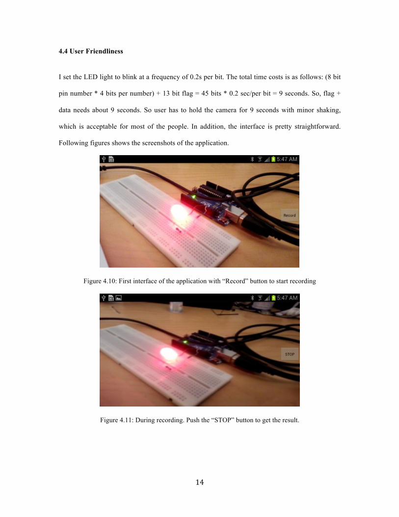
4.4 User Friendliness
I set the LED light to blink at a frequency of 0.2s per bit. The total time costs is as follows: (8 bit
pin number * 4 bits per number) + 13 bit flag = 45 bits * 0.2 sec/per bit = 9 seconds. So, flag +
data needs about 9 seconds. So user has to hold the camera for 9 seconds with minor shaking,
which is acceptable for most of the people. In addition, the interface is pretty straightforward.
Following figures shows the screenshots of the application.
Figure 4.10: First interface of the application with “Record” button to start recording
Figure 4.11: During recording. Push the “STOP” button to get the result.

! 15!
Figure 4.12: Result interface with 8-digit PIN number. Push “Finish” button to quit the application.
5. Discussion
This section discusses factors that may affect the robustness of the system as well as other
alternatives that were used during implementation.
5.1 Frame Rate Changes According to the Lighting Condition
During our experiments, the frame rate while recording a video changes with regards to the
lighting condition. For conditions where lights are dim the frame rate is around 15 fps, while
under natural lights, the frame rate is about 26fps. The change of frame rate raised a problem that
while we are decoding the images, and it adds to the difficulty of testing the program. It has to be
independent of the frame rates. Our algorithm stated in section 3.2 addresses this problem.
5.2 Detection of LED under Strong Lights
In places where surrounding lights are strong, the picture has low contrast. The resulting gray
scale image has fewer white pixel presented. As a result, there will be false prediction of whether
the light is on or not.
! 16!
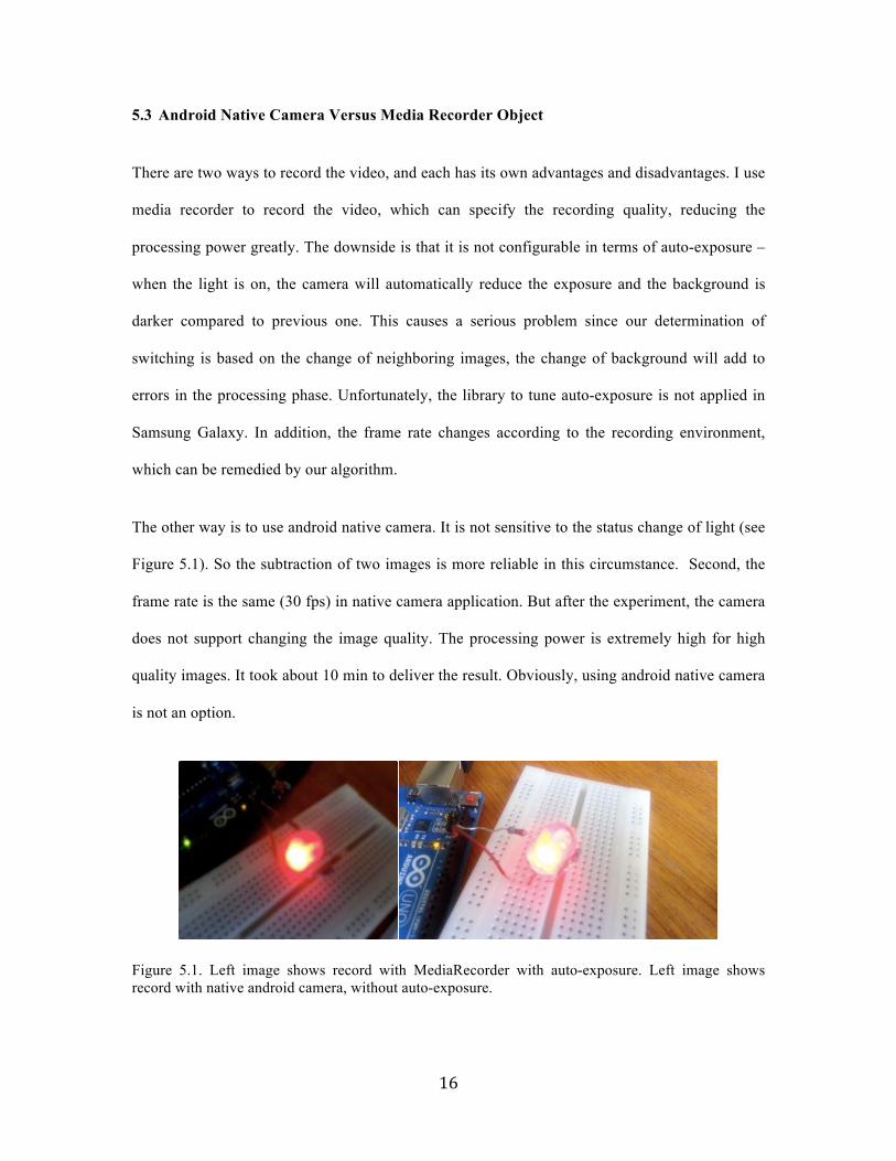
5.3 Android Native Camera Versus Media Recorder Object
There are two ways to record the video, and each has its own advantages and disadvantages. I use
media recorder to record the video, which can specify the recording quality, reducing the
processing power greatly. The downside is that it is not configurable in terms of auto-exposure –
when the light is on, the camera will automatically reduce the exposure and the background is
darker compared to previous one. This causes a serious problem since our determination of
switching is based on the change of neighboring images, the change of background will add to
errors in the processing phase. Unfortunately, the library to tune auto-exposure is not applied in
Samsung Galaxy. In addition, the frame rate changes according to the recording environment,
which can be remedied by our algorithm.
The other way is to use android native camera. It is not sensitive to the status change of light (see
Figure 5.1). So the subtraction of two images is more reliable in this circumstance. Second, the
frame rate is the same (30 fps) in native camera application. But after the experiment, the camera
does not support changing the image quality. The processing power is extremely high for high
quality images. It took about 10 min to deliver the result. Obviously, using android native camera
is not an option.
Figure 5.1. Left image shows record with MediaRecorder with auto-exposure. Left image shows record with native android camera, without auto-exposure.

! 17!
5.4 LED Light Switch Process
In most cases, video frame will capture the turning on status of the light as well as the process of
light fading out.
Figure 5.2 LED light switch process
The transition states will cause two considerable changes in terms of image difference. Figure 5.3
shows the two subtracted images from the above states.
Figure 5.3 Two subtracted images from the states
From the picture, you can see that both subtracted image will results in differences in different
areas, which can be misunderstood as a switch. I eliminate this possibility by not allowing
consecutive switches from one frame to another because it is not possible for the LED to switch
in only one frame time period.

! 18!
6. Recommendations
This section discusses the possible future improvements for the system.
6.1 Invariance to Distance
The application will be much more powerful if it can be used with distance beyond 10cm. To
realize that, one possible solution would be to find the relationship between the size of the object
(LED light in this case) and the distance.
6.2 Object Detection
For now, the application can tolerate minor shaking. If object detection is used in this case, the
camera can move in much larger area without loose track of the object. One solution would be to
know the translation and rotation of the camera and extract corresponding feature in the image.
6.3 Hardware Settings
In our project, we use Samsung Galaxy SIII for developing. Due to manufacturer settings, many
android camera API are not allowed in this smartphone such as auto-exposure settings in camera
parameter, video quality settings in native camera etc. If we can get the root access to the
smartphone, maybe it can have more degree of freedom to alter the hardware settings. However,
since the application is for common users, it is reasonable to develop an application that
commonly works in all kinds of smartphones.
7. Conclusion
The overall performance of the application can achieve very high accuracy with reasonable
distance as well as minor shaking. The system is very robust under natural light in indoor
environment, where the application can be commonly used. I have applied various techniques in
image processing and computer vision to enhance the performance. Besides, the project requires
great android development expertise. Future improvements of the application can be placed on

! 19!
the invariance of the distance as well as object recognition and tracking. Future application can be
using the IoT PIN number to execute the WPS registration protocol between the Smartphone and
the IoT device through the Access point to connect the IoT device to the Access Point, and
configure it to connect to the Access Point in a Wi-Fi environment.

! 20!
Reference
[1] Michael Chui, Markus Löffler, and Roger Roberts. The Internet of Things. March
2010 http://www.mckinseyquarterly.com/The_Internet_of_Things_2538
[2] Cory Janssen. Internet of Things (IoT).
http://www.techopedia.com/definition/28247/internet-of-things-iot
[3] Internet of Things. http://en.wikipedia.org/wiki/Internet_of_Thing
[4] Myriam Joire. Hands-on with the Electric Imp at Maker Faire. May 21st, 2012
http://www.engadget.com/2012/05/21/hands-on-with-the-electric-imp-at-maker-faire-
video/
[5] Quack, Till, Bay, Herbert and Gool, Luc V. Object Recognition for the Internet of
Things 2008
[6] Agrawal, Motilal, Konolige, Kurt. Real-time Localization in Outdoor Environments
using Stereo Vision and Inexpensive GPS 2006.

! 21!
[7] Akiko Kano, Kunio Doi, Heber MacMahon, Dayne D. Hassell, and Maryellen L.
Giger Digital image subtraction of temporally sequential chest images for detection of
interval change. 24 November 1993
[8]Anthony, Sebastian. TeleTouch: Turn your smartphone into a truly universal remote
control 2011