Embed Size (px)
Citation preview
Simple Optical Interference Method for the Inspectionof Solid Surfaces
J. P. M. Verbunt
Measuring methods based on optical interference are used to evaluate the surface roughness of solids.This article gives an example of a simple and accurate method.
Introduction
Since 1864, when Fizeau first used Newton ringsfor dilatometric measurements,' optical interferome-try has become an important resource in the field ofapplied optics. A number of instruments based onthe principles of optical interference now exist, ofwhich the interference microscope is one of the bestknown. This instrument is suitable for evaluatingthe surface structure of solids. In the present articlewe propose a method that gives the same or betterresults in a simpler and cheaper way by using a re-flection microscope in combination with a droplet ofa special liquid.
Optical Interference in a Wedge
If a transparent wedge of small angle, surroundedby air, is illuminated with monochromatic light, aninterference pattern is created. This interferencepattern obeys the well-known equation
2nd cos = mA, (1)
where n is the index of refraction and d the thicknessof the wedge, p the angle of refraction, m the orderof interference, and X the wavelength.2'3
Interference Microscope
The interference microscope can be used to evalu-ate the surface roughness of a solid. For this pur-pose the interference microscope is fitted with a ref-erence flat. In the case of a small angle between thisflat and the surface under examination, lines ofequal thickness are generated. Local changes in thisotherwise regular fringe pattern are a measure of the
The author is with Philips Research Laboratories, N. V. Phil-ips' Gloeilampenfabrieken, Eindhoven, Netherlands.
Received 26 December 1972.
surface roughness of the solid. It will be clear thatthe reference flat must be much more nearly perfectthan the surface under examination. Furthermore,it is important to limit the distance between thisplane and the surface under test, since a large dis-tance leads to decreasing of fringe contrast becausethe source is not purely monochromatic. These tworequirements, a well-defined surface and a small dis-tance, are satisfied in the method that we are aboutto propose here. Essentially, the top surface of aliquid spread over the sample under test is used as areference plane. This provides us, in the words ofLord Rayleigh, with a "natural flat" and makes itpossible to use any reflection microscope as an inter-ference microscope.
Droplet Interferometer
When a drop of transparent liquid is placed on asurface of a solid, it flows out into a flat drop withthe thickness at the edge gradually decreasing tozero. How this takes place depends on the interac-tion between the liquid and the solid, which in turndepends on the wetting properties of the liquid andthe structure of the surface to be wetted. Whenequilibrium has been reached, the edge of the liquidfilm can be considered as a transparent wedge, en-closed by the liquid-air and the liquid-solid inter-faces. If this wedge is illuminated by a monochro-matic light source, an interference pattern is created(Fig. 1).
The equation given above can be used for the in-terpretation of this pattern. Local changes in theotherwise regular fringe pattern are a measure of thesurface roughness of the test substance, as in thecase of the interference microscope (Figs. 2 and 3).Starting from the edge of the droplet, successivefringes indicate an increase in the liquid film thick-ness. This can be used to deduce whether a localshift in the fringe is caused by an elevation or a de-pression.
August 1973 / Vol. 12, No. 8 / APPLIED OPTICS 1839
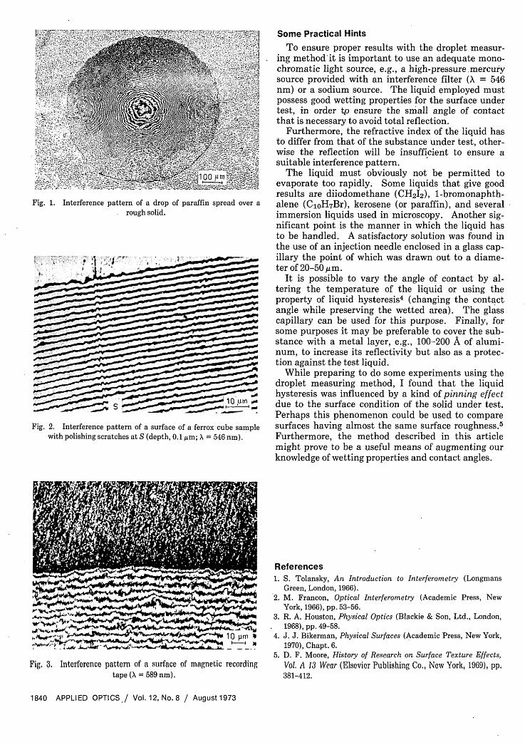
Fig. 1. Interference pattern of a drop of paraffin spread over arough solid.
Fig. 2. Interference pattern of a surface of a ferrox cube samplewith polishing scratches at S (depth, 0.1 ,um; X = 546 nm).
Some Practical Hints
To ensure proper results with the droplet measur-ing method it is important to use an adequate mono-chromatic light source, e.g., a high-pressure mercurysource provided with an interference filter ( = 546nm) or a sodium source. The liquid employed mustpossess good wetting properties for the surface undertest, in order o ensure the small angle of contactthat is necessary to avoid total reflection.
Furthermore, the refractive index of the liquid hasto differ from that of the substance under test, other-wise the reflection will be insufficient to ensure asuitable interference pattern.
The liquid must obviously not be permitted toevaporate too rapidly. Some liquids that give goodresults are diiodomethane (CH212), 1-bromonaphth-alene (CoH 7Br), kerosene (or paraffin), and severalimmersion liquids used in microscopy. Another sig-nificant point is the manner in which the liquid hasto be handled. A satisfactory solution was found inthe use of an injection needle enclosed in a glass cap-illary the point of which was drawn out to a diame-ter of 20-50 um.
It is possible to vary the angle of contact by al-tering the temperature of the liquid or using theproperty of liquid hysteresis4 (changing the contactangle while preserving the wetted area). The glasscapillary can be used for this purpose. Finally, forsome purposes it may be preferable to cover the sub-stance with a metal layer, e.g., 100-200 A of alumi-num, to increase its reflectivity but also as a protec-tion against the test liquid.
While preparing to do some experiments using thedroplet measuring method, I found that the liquidhysteresis was influenced by a kind of pinning effectdue to the surface condition of the solid under test.Perhaps this phenomenon could be used to comparesurfaces having almost the same surface roughness.5Furthermore, the method described in this articlemight prove to be a useful means of augmenting ourknowledge of wetting properties and contact angles.
Fig. 3. Interference pattern of a surface of magnetic recordingtape ( = 589 nm).
References1. S. Tolansky, An Introduction to Interferometry (Longmans
Green, London, 1966).2. M. Francon, Optical Interferometry (Academic Press, New
York, 1966), pp. 53-56.3. R. A. Houston, Physical Optics (Blackie & Son, Ltd., London,
1968), pp. 49-58.4. J. J. Bikerman, Physical Surfaces (Academic Press, New York,
1970), Chapt. 6.5. D. F. Moore, History of Research on Surface Texture Effects,
Vol. A 13 Wear (Elsevier Publishing Co., Now York, 1969), pp.381-412.
1840 APPLIED OPTICS / Vol. 12, No. 8 / August 1973


![Biomimetic Surface Structuring Using Laser Based ......of surfaces using nanosecond [13,14], picosecond [15] and femtosecond [16–19] laser sources. In particular, Direct Laser Interference](https://img.pdfslide.us/doc/110x75/60d5b405e309f7076249b3ea/biomimetic-surface-structuring-using-laser-based-of-surfaces-using-nanosecond.jpg)