Embed Size (px)
Citation preview
Answers for industry.
siemens.com/simocrane
Simple, fast, efficientSIMOCRANE in Drives
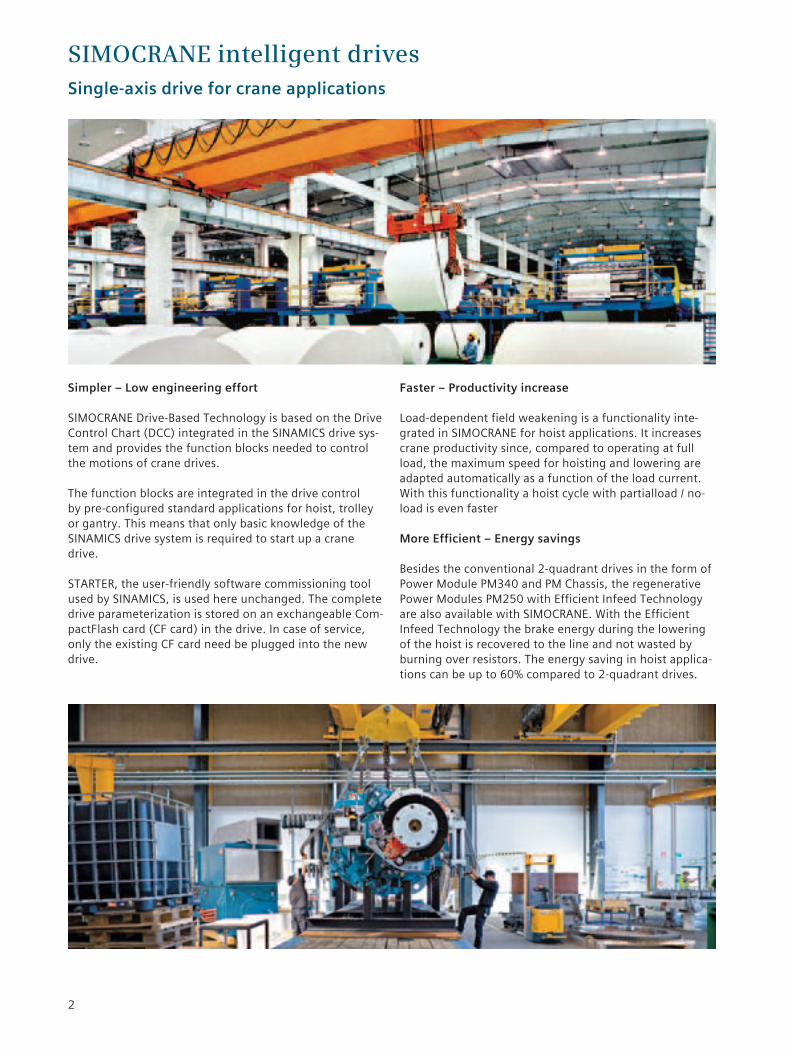
Simpler – Low engineering effort
SIMOCRANE Drive-Based Technology is based on the Drive Control Chart (DCC) integrated in the SINAMICS drive sys-tem and provides the function blocks needed to control the motions of crane drives.
The function blocks are integrated in the drive control by pre-configured standard applications for hoist, trolley or gantry. This means that only basic knowledge of the SINAMICS drive system is required to start up a crane drive.
STARTER, the user-friendly software commissioning tool used by SINAMICS, is used here unchanged. The complete drive parameterization is stored on an exchangeable Com-pactFlash card (CF card) in the drive. In case of service, only the existing CF card need be plugged into the new drive.
Faster – Productivity increase
Load-dependent field weakening is a functionality inte-grated in SIMOCRANE for hoist applications. It increases crane productivity since, compared to operating at full load, the maximum speed for hoisting and lowering are adapted automatically as a function of the load current. With this functionality a hoist cycle with partialload / no-load is even faster
More Efficient – Energy savings
Besides the conventional 2-quadrant drives in the form of Power Module PM340 and PM Chassis, the regenerative Power Modules PM250 with Efficient Infeed Technology are also available with SIMOCRANE. With the Efficient Infeed Technology the brake energy during the lowering of the hoist is recovered to the line and not wasted by burning over resistors. The energy saving in hoist applica-tions can be up to 60% compared to 2-quadrant drives.
SIMOCRANE intelligent drivesSingle-axis drive for crane applications
2

Modular
The SINAMICS S120 has a modular design and comprises a Control Unit (CU) and Power Module (PM) for the power range from 0.37 kW to 200 kW.
Safety Integrated
As in the SINAMICS, the crane drive technology is supple-mented by integrated safety functions. They support the simple implementation of innovative safety concepts which conform to standards. As safety functionality is integrated, they respond very rapidly in critical situations to prevent damage to man and crane. The Basic Functions are license-free. The Safety Integrated Extended Functions require the optional license for each drive.
SIMOCRANE meets SINAMICS
The SINAMICS S120 drive offers the optimum drive for each and every drive application – and all of the drives can be engineered, parameterized, commissioned and operated in a standard way.
Now SINAMICS, the universal drive platform launched on the worldwide market, is integrated with SIMOCRANE Drive-Based Technology, a crane technology platform representing an entrylevel solution for single-axis drive systems. It is designed for simple crane applications in all industrial sectors.
Standardized – Modular – Safe.
SINAMICS S120 Chassis unit from
90 to 200 kWSINAMICS S120 Blocksize drive units from 0.5 to 75 kW Control Unit
CU310-2
SINAMICS S120 AC Drivewith CU310-2
Motor
3-ph. 400 V AC
Crane control by master switch via I/O interface
PROFIBUS
Master switch
3
HoistTrolley Gantry

Modules and Setup
4
PROFIBUS-DP
Master switch
Hoist Trolley Gantry
Control (e.g. SIMATIC)
Selection of the SIMOCRANE in Drive is reduced to a minimum thanks to the modular system used.
Standard configuration for selectable crane controlDuring the guided commissioning the configuration of the drive parameters is made according to the selected mode of crane control.
Pre-limit switch
Limit switch
Acknowledge button
Lifting gear overload
Electrical stop
Mechanical stop
Brake check-back signal
Acknowledge button
24V
Brake control
“No fault“ signal
VE1
VE2
ES1
ES2
Qtt
ÜH
EST
MST
RB
QM
MM
AB
MKS
M
S2S+
S3S-
S4HN
TC2TC2
TC1TC1
MM24V24V MM
Setpoint stage S2Setpoint ±10 V
Setpoint stage S3
Notch / Setpoint stage S4High-speed notch
Travel command 2Travel command 2
Travel command 1Travel command 1
4 stage master switchMaster switch with setpoint potentiometer
The optimum power module can be selected intuitively based on the motor power required and the expected braking cycles.
The Control Unit for all single-axis drives for crane appli-cations is the CU310-2DP. With the available numbers of I/O’s and the PROFIBUS-DP on board no further mod-ules are required.
Optionally the BOP20 Basic Operator Panel can be installed. The BOP20 Basic Operator Panel is snapped onto the CU310-2DP and may be used to acknowledge faults, set parameters and read diagnostic information (e.g. alarm and fault messages).
The SIMOCRANE Drive-Based Technology provides thecrane technology as function blocks on DVD and theCompactFlash card with the SINAMICS firmware.
Crane control via PROFIBUS-DP
Crane control via I/O interface

Functionality and configuration
Drive configuration
With STARTER, the standard SINAMICS commissioning tool, the commissioning is simple and transparent. Initial commissioning is guided by a wizard which makes all the basic settings in the drive. Therefore, getting a motor up and running is merely a question of setting a few of the drive parameters as part of the drive configuration process.
Activating the crane control system
The crane control function blocks are switched internally by simply selecting the axis function (either hoist, trolley, or gantry) and the set value input (via PROFIBUS DP or I/O configuration). The function blocks are then integrated in the drive parameterization. The default parameterization of function blocks is individually adaptable using the STARTER software.
5
Functionality of SIMOCRANE Drive-based Technology
Load-dependent field weakening Calculates additional speed setpoints, depending on the load. Partial loads automatically run at higher speed than full loads.
Prelimit switch (selectable limitation) Allows you to limit the drive spped when reaching a predefined prelimit switch.
Start pulse Prevents “load sag“ when starting hoist gear with a suspended load.
Current distribution monitoring Compares the current setpoints or actual values of the master and slave and sends a message if a specified value is deviated.
Master switch Enables drive movement with high precision via a directly connected master switch for manual positioning.
Overspeed monitoring Monitors overspeed or detects deviations between the speed setpoints and actual values.
Time-optimized positioning for single axis Enables precise drive movement to the target position at the preset maximum speed and acceleration/deceleration in a shortest time.
Master slave torque control When two motors are operated on a common shaft, the master specifies the torque setpoint for the slave. The master and slave drives are linked via the application.
Safety Integrated Basic Functions:•Safe torque off (STO)•Safe brake control (SBC)•Safe stop 1 (SS1)
Safety Integrated Extended Functions:•Safe stop 2 (SS2)•Safe operating stop (SOS)•Safely-limited speed (SLS)•Safe speed monitor (SSM)•Safe direction (SDI)

6
Power Module Control Unit SIMOCRAINE DBT Single-axis drive for cranes
Control Units
Type Function Order No
CU310-2 DP Control unit with PROFIBUS (DP) 6SL3040-1LA00-0AA0
SIMOCRANE
Type Function Order No
SIMOCRANE DBT CompactFlash Card with SINAMICS Firmware for CU310-2 and CD with crane specific function blocks for crane applications
6GA7270-1AA11-0AA0
STARTER User-friendly commissioning tool for SINAMICS for commis sion-ing, optimizing and diagnostics
6SL3072-0AA00-0AG0
Optional – Operator panel
Type Function Order No
Basic Operator Panel BOP20 Basic operator panel with backlit two-line display area and 6 keys for acknowledge faults, set parameters and read diagnostic information
6SL3055-0AA00-4BA0
Optional – Safety
Type Function Order No
Extended Safety Licence Certificate of Licence for Safety Integrated Extended Functions for upgrading the licence of a CompactFlash Card.
6SL3074-0AA10-0AA0
Terminal Module TM54F External extension with 10 fail-safe digital inputs and 4 fail-safe outputs
6SL3055-0AA00-3BA0
Optional – External Encoder Interface
Type Function Order No
Sensor Module SMC10 Evaluation of 2-pole and multi-pole resolver 6SL3055-0AA00-5AA3
Sensor Module SMC20 Evaluation of incremental encoder sin/cos 1Vpp, absolute enco-der EnDat and SSI encoder with incremental signals sin/cos 1Vpp
6SL3055-0AA00-5BA3
Ordering data

7
Power Modules, 2-Quadrant Blocksize drive units from 1.1 to 75 kW
Power PH Output current IH Frame size Order No.
kW A PM340 Line reactor
Power Supply 3 AC 380 … 480 V
0,37 1,1 FSA 6SL3210-1SE11-3UA0 6SE6400-3CC00-2AD3
0,55 1,5 FSA 6SL3210-1SE11-7UA0 6SE6400-3CC00-2AD3
0,75 1,9 FSA 6SL3210-1SE12-2UA0 6SE6400-3CC00-4AD3
1,1 2,7 FSA 6SL3210-1SE13-1UA0 6SE6400-3CC00-4AD3
1,5 3,6 FSA 6SL3210-1SE14-1UA0 6SE6400-3CC00-6AD3
2,2 5,2 FSB 6SL3210-1SE16-0_A0 6SL3203-0CD21-0AA0
3 6,8 FSB 6SL3210-1SE17-7_A0 6SL3203-0CD21-0AA0
4 9,1 FSB 6SL3210-1SE21-0_A0 6SL3203-0CD21-4AA0
5,5 14 FSC 6SL3210-1SE21-8_A0 6SL3203-0CD22-2AA0
7,5 21 FSC 6SL3210-1SE22-5_A0 6SL3203-0CD22-2AA0
11 27 FSC 6SL3210-1SE23-2_A0 6SL3203-0CD23-5AA0
15 33 FSD 6SL3210-1SE23-8_A0 6SL3203-0CJ24-5AA0
18,5 40 FSD 6SL3210-1SE24-5_A0 6SL3203-0CJ24-5AA0
22 48 FSD 6SL3210-1SE26-0_A0 6SL3203-0CD25-3AA0
30 65 FSE 6SL3210-1SE27-5_A0 6SL3203-0CJ28-6AA0
37 80 FSE 6SL3210-1SE31-0_A0 6SL3203-0CJ28-6AA0
45 95 FSF 6SL3210-1SE31-1_A0 6SE6400-3CC11-2FD0
55 115 FSF 6SL3210-1SE31-5_A0 6SE6400-3CC11-2FD0
75 155 FSF 6SL3210-1SE31-8_A0 6SE6400-3CC11-7FD0 U = without line filter A = with integrated line filter
Power Modules, 2-Quadrant Chassis unit from 90 to 200 kW
Power PH Output current IH Frame size Order No.
kW A PM Chassis Line reactor
Power Supply 3 AC 380 … 480 V
90 178 FSFX 6SL3310-1TE32-1AA3 6SL3000-0CE32-3AA0
110 233 FSFX 6SL3310-1TE32-6AA3 6SL3000-0CE32-8AA0
132 277 FSGX 6SL3310-1TE33-1AA3 6SL3000-0CE33-3AA0
160 340 FSGX 6SL3310-1TE33-8AA3 6SL3000-0CE35-1AA0
200 438 FSGX 6SL3310-1TE35-0AA3 6SL3000-0CE35-1AA0
Power Modules, 4-Quadrant Blocksize drive units from 5.5 to 75 kW
Power PH Output current IH Frame size Order No.
kW A PM250
Power Supply 3 AC 380 … 480 V
5,5 13,2 FSC 6SL3225-0BE25-5AA1
7,5 19 FSC 6SL3225-0BE27-5AA1
11 26 FSC 6SL3225-0BE31-1AA1
15 32 FSD 6SL3225-0BE31-5_A0
18,5 38 FSD 6SL3225-0BE31-8_A0
22 45 FSD 6SL3225-0BE32-2_A0
30 60 FSE 6SL3225-0BE33-0_A0
37 75 FSE 6SL3225-0BE33-7_A0
45 90 FSF 6SL3225-0BE34-5_A0
55 110 FSF 6SL3225-0BE35-5_A0
75 145 FSF 6SL3225-0BE37-5_A0 U = without line filter A = with integrated line filter

Subject to change without prior notice Order No.: E20001-A1750-P620-X-7600 Dispo 06372 SCHÖ/10809304 HEBE.52.3.01 SB 12123.0 Printed in Germany © Siemens AG 2012
The information provided in this brochure contains merely general descriptions or characteristics of performance which in case of actual use do not always apply as described or which may change as a result of further development of the products. An obligation to provide the respective characteristics shall only exist if expressly agreed in the terms of contract.All product designations may be trademarks or product names of Siemens AG or supplier companies whose use by third parties for their own purposes could violate the rights of the owners.
Siemens AG Industry Sector Motion Control Systems P.O. Box 31 80 91050 ERLANGEN GERMANY
Technical DataSIMOCRANE in Drive
Power unit PM340 PM Chassis PM 250Drive type AC/AC unit, modularDegree of protection IP20Line supply voltage 3 AC 380 … 480 V ±10%Line frequency 47 … 63 HzRequired line short-circuit voltage Uk ≤1%or
> 1% with line reactor≤1%
Overload capability for base load current IH
1,5 x IH for 60 seconds within 300 seconds1,76 x IH for 30 seconds within 300 seconds
1,5 x IH for 57 secondswithin 300 seconds
Braking method Dynamic braking Energy recovery with max. IN
Braking chopper Integrated Optional –Max. output voltage 0…93 % line voltage 0..87 % line voltageRated pulse frequency 4 kHz 2 kHz 4 kHzOpen-loop/closed-loop control techniques
Vector control / U/f control
Output frequency 0…300 HzEncoder interface onboard 1 encoder evaluation for TTL/HTL incremental encoders and
SSI encoders without incremental signalsParameterizable digital inputs/outputs 5 DI, 8 DI/DO, 1 AIParameterizable fail-safe digital inputs/outputs
3 F-DI, 1 F-DO
Temperature sensor input 1 for evaluation of KTY84-130 or PTCDRIVE-CLiQ 1 connectionSafety Integrated Basic functions
STO, SBC, SS1
Safety Integrated Extended functions
SS2, SLS, SOS, SSM, SDI
Motors Three-phase induction motors
Dimensions (depth without CU)
Frame size FSA FSB FSC FSD FSE FSF FSFX FSGXWidth (mm) 73 153 189 275 275 350 326 326Depth (mm) 145 165 185 204 204 316 356 549Height (mm), without line filter 173 270 334 419 499 634 1400 1533Height (mm), with line filter – 270 334 512 635 934 – –