Embed Size (px)
Citation preview
Simple and Efficient Visual Gaze Estimation
Roberto [email protected]
Nicu [email protected]
Intelligent Systems LabAmsterdam
Kruislaan 403, 1018SJAmsterdam, The Netherlands
Theo [email protected]
ABSTRACTIn this paper we combine a state of the art eye center locatorand a new eye corner locator into a system which estimatesthe visual gaze of a user in a controlled environment (e.g.sitting in front of a screen). In order to reduce to a minimumthe computational costs, the eye corner locator is built uponthe same technology of the eye center locator, tweaked forthe specific task. If high mapping precision is not a priorityof the application, we claim that the system can achieveacceptable accuracy without the requirements of additionaldedicated hardware. We believe that this could bring newgaze based methodologies for human-computer interactionsinto the mainstream.
Categories and Subject DescriptorsI.4.9 [Image Processing and Computer Vision]: Appli-cations; J.7 [Computers in Other Systems]: Commandand control
General TermsAlgorithms
KeywordsEye tracking, ambient intelligence, visual gaze, HCI
1. INTRODUCTIONEye location and tracking and the related visual gaze es-timation are important tasks in many computer vision ap-plications and research [1]. Some of the most common ex-amples are the application to user attention and gaze indriving and marketing scenarios, and control devices fordisabled people. Eye location/tracking techniques can bedivided into three distinct modalities [10]: (1) Electro ocu-lography, which records the electric potential differences ofthe skin surrounding the ocular cavity; (2) scleral contactlens/search coil, which uses a mechanical reference mountedon a contact lens, and (3) photo/video oculography, whichuses image processing techniques to locate the center of the
eye. Unfortunately, the common problem of the above tech-niques is the use of intrusive and expensive sensors [4]. Whilephoto/video oculography is considered the least invasive ofthe modalities, commercially available trackers still requirethe user to be either equipped with a head mounted device,or to use a high resolution camera combined with a chinrestto limit the allowed head movement. Furthermore, daylightapplications are precluded due to the common use of ac-tive infrared (IR) illumination, used to obtain accurate eyelocation through corneal reflection. Non infrared appear-ance based eye locators [2, 3, 5, 7, 8, 12, 11, 15, 19] cansuccessfully locate eye regions, yet are unable to track eyemovements accurately.
The goal of this paper is to build an eye tracker that canquickly and accurately locate and track eye centers and eyecorners in low resolution images and videos (coming from asimple web cam) and map them on the screen plane. Therest of this paper is structured as follows: For complete-ness, the theory behind the used framework is explained insection 2 (for additional details refer to [16]). Section 3 de-scribes how to accurately detect an eye center starting froman image of an eye, Section 4 applies the same rationale toeye corner location, with the help of some simple geometri-cal constraints. Finally, in section 5 we will discuss how toeasily map eye and corner location to screen coordinates.
2. ISOCENTERS ESTIMATIONThe isophotes of an image are curves connecting points ofequal intensity. Since isophotes do not intersect each other,an image can be fully described by its isophotes. Further-more, the shape of the isophotes is independent to rotationand linear lighting changes [14]. To better illustrate the wellknown isophote framework, it is opportune to introduce thenotion of intrinsic geometry, geometry with a locally definedcoordinate system. In every point of the image, a local co-ordinate frame is fixed in such a way that it points in thedirection of the maximal change of the intensity, which cor-responds to the direction of the gradient. This referenceframe {v, w} is referred to as the gauge coordinates. Itsframe vectors w and v are defined as:
w ={Lx, Ly}√L2
x + L2y
; v = ⊥w; (1)
where Lx and Ly are the first-order derivatives of the lu-minance function L(x, y) in the x and y dimension, respec-tively. In this setting, a derivative in the w direction is thegradient itself, and the derivative in the v direction (perpen-
dicular to the gradient) is 0 (no intensity change along theisophote). In this coordinate system, an isophote is definedas L(v, w(v)) = constant and its curvature κ is defined asthe change w′′ of the tangent vector w′ which in Cartesiancoordinates becomes [9, 17, 16]
κ = −Lvv
Lw= −
L2yLxx − 2LxLxyLy + L2
xLyy
(L2x + L2
y)3/2. (2)
Since the curvature is the reciprocal of the radius, we can re-verse Eq. (2) to obtain the radius of the circle that generatedthe curvature of the isophote. The radius is meaningless if itis not combined with orientation and direction. The orien-tation can be estimated from the gradient, but its directionwill always point towards the highest change in the lumi-nance. However, the sign of the isophote curvature dependson the intensity of the outer side of the curve (for a brighterouter side the sign is positive). Thus, by multiplying thegradient with the inverse of the isophote curvature, the du-ality of the isophote curvature helps in disambiguating thedirection of the center. Since the gradient can be written as{Lx,Ly}
Lw, we have
D(x, y) ={Lx, Ly}
Lw
(− Lw
Lvv
)= −{Lx, Ly}
Lvv
= −{Lx, Ly}(L2
x + L2y)
L2yLxx − 2LxLxyLy + L2
xLyy. (3)
where D(x, y) are the displacement vectors to the estimatedposition of the centers, which can be mapped into an accu-mulator, hereinafter “centermap”. Since every vector gives arough estimate of the center, we can convolve the accumula-tor with a Gaussian kernel so that each cluster of votes willform a single center estimate. Furthermore, the contribu-tion of each vector can be weighted according to a relevancemechanism. The main idea is that by collecting and averag-ing local evidence of curvature, the discretization problemsin a digital image could be lessened and accurate center es-timation could be achieved.
In order to achieve this goal, only the parts of the isophoteswhich are meaningful for our purposes should be used, thatis, the ones that follow the edges of an object. This selectioncan be performed by using the curvedness [13]:
curvedness =√
L2xx + 2L2
xy + L2yy. (4)
We note that the curvedness has low response on flat sur-faces and edges, whereas it yields high response in placeswhere the isophote density is maximal. As observed before,the isophote density is maximal around the edges of an ob-ject, meaning that by selecting the parts of the isophoteswhere the curvedness is maximal, they will likely follow anobject boundary and locally agree on the same center. Theadvantage of this approach over a pure edge based methodis that, by using the curvedness as the voting scheme for theimportance of the vote, every pixel in the image may con-tribute to a decision. By summing the votes, we obtain highresponse on isocentric isophotes patterns which respect theconstraint of being near edges. We call these high responses“isocenters”, or ICs.
3. EYE CENTER LOCATIONRecalling that the sign of the isophote curvature dependson the intensity of the outer side of the curve, we observe
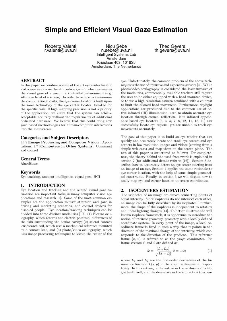
Figure 1: The source image, the obtained centermapand the 3D representation of the latter
that a negative sign indicates a change in the direction ofthe gradient (from brighter to darker areas). Therefore, it ispossible to discriminate between dark and bright centers byanalyzing the sign of the curvature. Regarding the specifictask of cornea and iris location, it can be assumed that thesclera is brighter than the cornea and the iris, so we shouldignore the votes in which the curvature is positive, that is,where it agrees with the direction of the gradient. As aconsequence, the maximum isocenter (MIC) obtained willrepresent the estimated center of the eye. The result of thisprocedure on an eye image is shown in figure 1. From the3D plot it is clear where the MIC is, but we can expect thatcertain lighting conditions and occlusions from the eyelidsto result in a wrong eye center estimate. To cope with thisproblem, we use the mean shift algorithm for density estima-tion. Mean shift (MS) usually operates on back-projectedimages in which probabilities are assigned to pixels based onthe color probability distribution of a target, weighted by aspatial kernel over pixel locations. It then finds the localmaximum of this distribution by gradient ascent [6]. Here,the mean shift procedure is directly applied to the centermapresulting from our method, under the assumption that themost relevant isocenter should have higher density of votes,and that wrong MICs are not so distant from the correctone (on an eye corner). A mean shift search window is ini-tialized on the centermap, centered on the found MIC. Thealgorithm then iterates to converge to a region with maxi-mal votes distribution. After some iteration, the isocenterclosest to the center of the search window is selected as thenew eye center estimate.
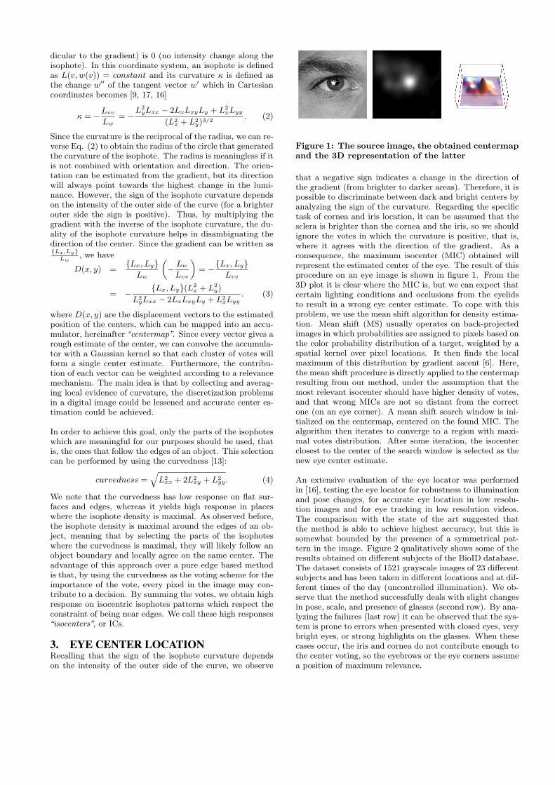
An extensive evaluation of the eye locator was performedin [16], testing the eye locator for robustness to illuminationand pose changes, for accurate eye location in low resolu-tion images and for eye tracking in low resolution videos.The comparison with the state of the art suggested thatthe method is able to achieve highest accuracy, but this issomewhat bounded by the presence of a symmetrical pat-tern in the image. Figure 2 qualitatively shows some of theresults obtained on different subjects of the BioID database.The dataset consists of 1521 grayscale images of 23 differentsubjects and has been taken in different locations and at dif-ferent times of the day (uncontrolled illumination). We ob-serve that the method successfully deals with slight changesin pose, scale, and presence of glasses (second row). By ana-lyzing the failures (last row) it can be observed that the sys-tem is prone to errors when presented with closed eyes, verybright eyes, or strong highlights on the glasses. When thesecases occur, the iris and cornea do not contribute enough tothe center voting, so the eyebrows or the eye corners assumea position of maximum relevance.
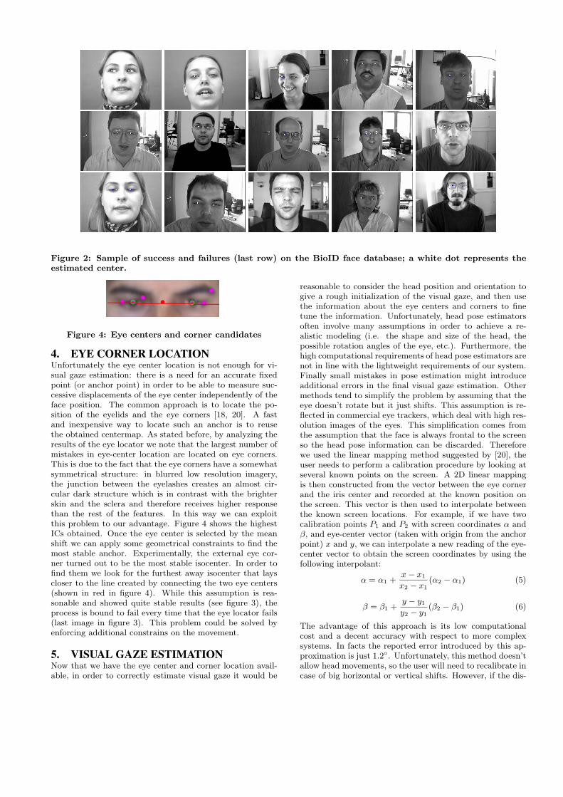
Figure 2: Sample of success and failures (last row) on the BioID face database; a white dot represents theestimated center.
Figure 4: Eye centers and corner candidates
4. EYE CORNER LOCATIONUnfortunately the eye center location is not enough for vi-sual gaze estimation: there is a need for an accurate fixedpoint (or anchor point) in order to be able to measure suc-cessive displacements of the eye center independently of theface position. The common approach is to locate the po-sition of the eyelids and the eye corners [18, 20]. A fastand inexpensive way to locate such an anchor is to reusethe obtained centermap. As stated before, by analyzing theresults of the eye locator we note that the largest number ofmistakes in eye-center location are located on eye corners.This is due to the fact that the eye corners have a somewhatsymmetrical structure: in blurred low resolution imagery,the junction between the eyelashes creates an almost cir-cular dark structure which is in contrast with the brighterskin and the sclera and therefore receives higher responsethan the rest of the features. In this way we can exploitthis problem to our advantage. Figure 4 shows the highestICs obtained. Once the eye center is selected by the meanshift we can apply some geometrical constraints to find themost stable anchor. Experimentally, the external eye cor-ner turned out to be the most stable isocenter. In order tofind them we look for the furthest away isocenter that layscloser to the line created by connecting the two eye centers(shown in red in figure 4). While this assumption is rea-sonable and showed quite stable results (see figure 3), theprocess is bound to fail every time that the eye locator fails(last image in figure 3). This problem could be solved byenforcing additional constrains on the movement.
5. VISUAL GAZE ESTIMATIONNow that we have the eye center and corner location avail-able, in order to correctly estimate visual gaze it would be
reasonable to consider the head position and orientation togive a rough initialization of the visual gaze, and then usethe information about the eye centers and corners to finetune the information. Unfortunately, head pose estimatorsoften involve many assumptions in order to achieve a re-alistic modeling (i.e. the shape and size of the head, thepossible rotation angles of the eye, etc.). Furthermore, thehigh computational requirements of head pose estimators arenot in line with the lightweight requirements of our system.Finally small mistakes in pose estimation might introduceadditional errors in the final visual gaze estimation. Othermethods tend to simplify the problem by assuming that theeye doesn’t rotate but it just shifts. This assumption is re-flected in commercial eye trackers, which deal with high res-olution images of the eyes. This simplification comes fromthe assumption that the face is always frontal to the screenso the head pose information can be discarded. Thereforewe used the linear mapping method suggested by [20], theuser needs to perform a calibration procedure by looking atseveral known points on the screen. A 2D linear mappingis then constructed from the vector between the eye cornerand the iris center and recorded at the known position onthe screen. This vector is then used to interpolate betweenthe known screen locations. For example, if we have twocalibration points P1 and P2 with screen coordinates α andβ, and eye-center vector (taken with origin from the anchorpoint) x and y, we can interpolate a new reading of the eye-center vector to obtain the screen coordinates by using thefollowing interpolant:
α = α1 +x− x1
x2 − x1(α2 − α1) (5)
β = β1 +y − y1
y2 − y1(β2 − β1) (6)
The advantage of this approach is its low computationalcost and a decent accuracy with respect to more complexsystems. In facts the reported error introduced by this ap-proximation is just 1.2◦. Unfortunately, this method doesn’tallow head movements, so the user will need to recalibrate incase of big horizontal or vertical shifts. However, if the dis-
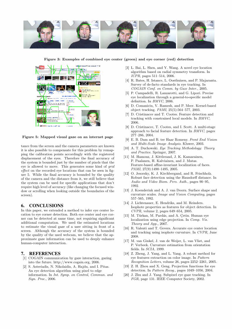
Figure 3: Examples of combined eye center (green) and eye corner (red) detection
Figure 5: Mapped visual gaze on an internet page
tance from the screen and the camera parameters are knownit is also possible to compensate for this problem by remap-ping the calibration points accordingly with the registereddisplacement of the eyes. Therefore the final accuracy ofthe system is bounded just by the number of pixels that theeye is allowed to move. This generates some kind of grideffect on the recorded eye locations that can be seen in fig-ure 5. While the final accuracy is bounded by the qualityof the camera and the distance from it, we still believe thatthe system can be used for specific applications that don’trequire high level of accuracy (like changing the focused win-dow or scrolling when looking outside the boundaries of thescreen).
6. CONCLUSIONSIn this paper, we extended a method to infer eye center lo-cation to eye corner detection. Both eye center and eye cor-ner can be detected at same time, not requiring significantadditional computation. We used the estimated locationsto estimate the visual gaze of a user sitting in front of ascreen. Although the accuracy of the system is boundedby the quality of the used webcam, we believe that the ap-proximate gaze information can be used to deeply enhancehuman-computer interaction.
7. REFERENCES[1] COGAIN communication by gaze interaction, gazing
into the future. http://www.cogain.org, 2006.
[2] S. Asteriadis, N. Nikolaidis, A. Hajdu, and I. Pitas.An eye detection algorithm using pixel to edgeinformation. In Int. Symp. on Control, Commun. andSign. Proc., 2006.
[3] L. Bai, L. Shen, and Y. Wang. A novel eye locationalgorithm based on radial symmetry transform. InICPR, pages 511–514, 2006.
[4] R. Bates, H. Istance, L. Oosthuizen, and P. Majaranta.Survey of de-facto standards in eye tracking. InCOGAIN Conf. on Comm. by Gaze Inter., 2005.
[5] P. Campadelli, R. Lanzarotti, and G. Lipori. Preciseeye localization through a general-to-specific modeldefinition. In BMVC, 2006.
[6] D. Comaniciu, V. Ramesh, and P. Meer. Kernel-basedobject tracking. PAMI, 25(5):564–577, 2003.
[7] D. Cristinacce and T. Cootes. Feature detection andtracking with constrained local models. In BMVC,2006.
[8] D. Cristinacce, T. Cootes, and I. Scott. A multi-stageapproach to facial feature detection. In BMVC, pages277–286, 2004.
[9] E. B. Dam and B. ter Haar Romeny. Front End Visionand Multi-Scale Image Analysis. Kluwer, 2003.
[10] A. T. Duchowski. Eye Tracking Methodology: Theoryand Practice. Springer, 2007.
[11] M. Hamouz, J. Kittlerand, J. K. Kamarainen,P. Paalanen, H. Kalviainen, and J. Matas.Feature-based affine-invariant localization of faces.PAMI, 27(9):1490–1495, 2005.
[12] O. Jesorsky, K. J. Kirchbergand, and R. Frischholz.Robust face detection using the Hausdorff distance. InAudio and Video Biom. Pers. Auth., pages 90–95,1992.
[13] J. Koenderink and A. J. van Doorn. Surface shape andcurvature scales. Image and Vision Computing, pages557–565, 1992.
[14] J. Lichtenauer, E. Hendriks, and M. Reinders.Isophote properties as features for object detection. InCVPR, volume 2, pages 649–654, 2005.
[15] M. Turkan, M. Pardas, and A. Cetin. Human eyelocalization using edge projection. In Comp. Vis.Theory and App., 2007.
[16] R. Valenti and T. Gevers. Accurate eye center locationand tracking using isophote curvature. In CVPR, June2008.
[17] M. van Ginkel, J. van de Weijer, L. van Vliet, andP. Verbeek. Curvature estimation from orientationfields. In SCIA, 1999.
[18] Z. Zheng, J. Yang, and L. Yang. A robust method foreye features extraction on color image. In PatternRecognition Letters, volume 26, pages 2252–2261, 2005.
[19] Z. H. Zhou and X. Geng. Projection functions for eyedetection. In Pattern Recog., pages 1049–1056, 2004.
[20] J. Zhu and J. Yang. Subpixel eye gaze tracking. InFGR, page 131. IEEE Computer Society, 2002.