Embed Size (px)
Citation preview
APPLICATION NOTES
Last updated on January 2018 © 2018 FRACTUS ANTENNAS, S.L. - 1
SIMPLE AND COST EFFICIENT SMART METER ANTENNA INTEGRATION
ALL mXTENDTM (FR01-S4-220) and RUN mXTENDTM (FR01-S4-224) AN for Smart Meters 698 – 960 MHz and 1710 – 2170 MHz
Fractus Antennas specializes in enabling effective mobile communications by designing and manufacturing optimized antenna products that will make your wireless devices more competitive. Our mission is to transform our clients’ product development processes with innovative components that accelerate time-to-market without compromising functionality.
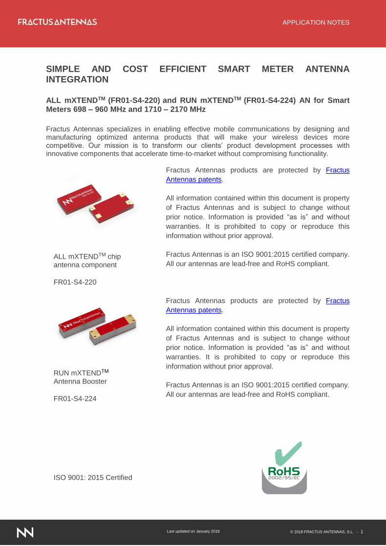
ALL mXTENDTM chip antenna component
FR01-S4-220
Fractus Antennas products are protected by Fractus
Antennas patents.
All information contained within this document is property
of Fractus Antennas and is subject to change without
prior notice. Information is provided “as is” and without
warranties. It is prohibited to copy or reproduce this
information without prior approval.
Fractus Antennas is an ISO 9001:2015 certified company.
All our antennas are lead-free and RoHS compliant.
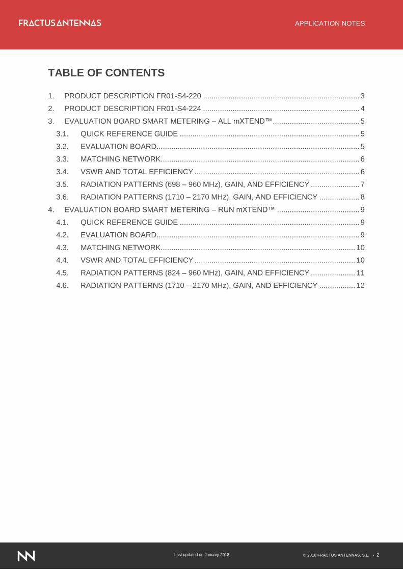
RUN mXTENDTM Antenna Booster
FR01-S4-224
Fractus Antennas products are protected by Fractus
Antennas patents.
All information contained within this document is property
of Fractus Antennas and is subject to change without
prior notice. Information is provided “as is” and without
warranties. It is prohibited to copy or reproduce this
information without prior approval.
Fractus Antennas is an ISO 9001:2015 certified company.
All our antennas are lead-free and RoHS compliant.
ISO 9001: 2015 Certified
APPLICATION NOTES
Last updated on January 2018 © 2018 FRACTUS ANTENNAS, S.L. - 2
TABLE OF CONTENTS
1. PRODUCT DESCRIPTION FR01-S4-220 .......................................................................... 3
2. PRODUCT DESCRIPTION FR01-S4-224 .......................................................................... 4
3. EVALUATION BOARD SMART METERING – ALL mXTEND™ ......................................... 5
3.1. QUICK REFERENCE GUIDE ..................................................................................... 5
3.2. EVALUATION BOARD ................................................................................................ 5
3.3. MATCHING NETWORK .............................................................................................. 6
3.4. VSWR AND TOTAL EFFICIENCY .............................................................................. 6
3.5. RADIATION PATTERNS (698 – 960 MHz), GAIN, AND EFFICIENCY ....................... 7
3.6. RADIATION PATTERNS (1710 – 2170 MHz), GAIN, AND EFFICIENCY ................... 8
4. EVALUATION BOARD SMART METERING – RUN mXTEND™ ....................................... 9
4.1. QUICK REFERENCE GUIDE ..................................................................................... 9
4.2. EVALUATION BOARD ................................................................................................ 9
4.3. MATCHING NETWORK ............................................................................................ 10
4.4. VSWR AND TOTAL EFFICIENCY ............................................................................ 10
4.5. RADIATION PATTERNS (824 – 960 MHz), GAIN, AND EFFICIENCY ..................... 11
4.6. RADIATION PATTERNS (1710 – 2170 MHz), GAIN, AND EFFICIENCY ................. 12
APPLICATION NOTES
Last updated on January 2018 © 2018 FRACTUS ANTENNAS, S.L. - 3
1. PRODUCT DESCRIPTION FR01-S4-220
The rate of smart meter implementation is projected to continue to grow as governments
implement programs to encourage their deployment, helping providers get more detailed
information which in turn allows them to better match utility generation with customer
consumption. In this application note we illustrate how to use the ALL mXTENDTM chip antenna
component (FR01-S4-220) for operating at the 698-960MHz and 1710-2170MHz frequency
ranges used in smart meters. Additionally, we have performed our tests using an Evaluation
Board the size of a typical smart meter to provide the most relevant results possible for those
who design smart meters.
The ALL mXTENDTM is perfect for providing cost savings in your smart meter production. It is
often a lower cost component than an external antenna and being SMD pick and place it
provides savings on assembly labor costs. Additionally, as this antenna is mounted internally it
provides the further benefit of increased protection against environmental factors versus an
external antenna. The same antenna part can be used to cover different frequency ranges,
since it offers the antenna designer the flexibility of selecting the frequency regions to operate
through just the customization of the matching network.
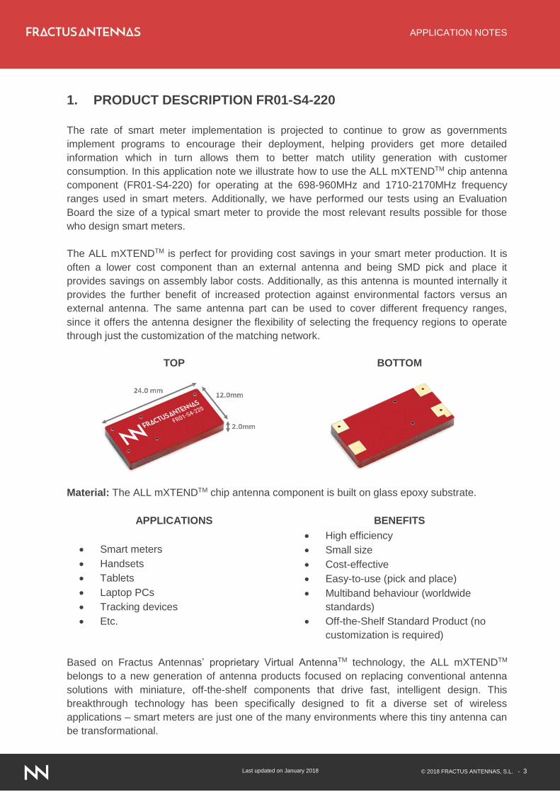
TOP BOTTOM
Material: The ALL mXTENDTM chip antenna component is built on glass epoxy substrate.
APPLICATIONS BENEFITS
Smart meters
Handsets
Tablets
Laptop PCs
Tracking devices
Etc.
High efficiency
Small size
Cost-effective
Easy-to-use (pick and place)
Multiband behaviour (worldwide
standards)
Off-the-Shelf Standard Product (no
customization is required)
Based on Fractus Antennas’ proprietary Virtual AntennaTM technology, the ALL mXTENDTM
belongs to a new generation of antenna products focused on replacing conventional antenna
solutions with miniature, off-the-shelf components that drive fast, intelligent design. This
breakthrough technology has been specifically designed to fit a diverse set of wireless
applications – smart meters are just one of the many environments where this tiny antenna can
be transformational.
APPLICATION NOTES
Last updated on January 2018 © 2018 FRACTUS ANTENNAS, S.L. - 4
2. PRODUCT DESCRIPTION FR01-S4-224
The rate of smart meter implementation is projected to continue to grow as governments
implement programs to encourage their deployment, helping providers get more detailed
information which in turn allows them to better match utility generation with customer
consumption. In this application note we illustrate how to use the RUN mXTENDTM chip antenna
component (FR01-S4-220) for operating at the 824-960MHz and 1710-2170MHz frequency
ranges used in smart meters. Additionally, we have performed our tests using an Evaluation
Board the size of a typical smart meter to provide the most relevant results possible for those
who design smart meters.
The RUN mXTENDTM is perfect for providing cost savings in your smart meter production. It is
often a lower cost component than an external antenna and being SMD pick and place it
provides savings on assembly labor costs. Additionally, as this antenna is mounted internally it
provides the further benefit of increased protection against environmental factors versus an
external antenna. The same antenna part can be used to cover different frequency ranges,
since it offers the antenna designer the flexibility of selecting the frequency regions to operate
through just the customization of the matching network.
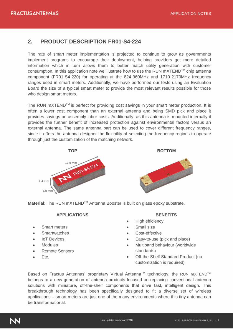
TOP BOTTOM
Material: The RUN mXTENDTM Antenna Booster is built on glass epoxy substrate.
APPLICATIONS BENEFITS
Smart meters
Smartwatches
IoT Devices
Modules
Remote Sensors
Etc.
High efficiency
Small size
Cost-effective
Easy-to-use (pick and place)
Multiband behaviour (worldwide
standards)
Off-the-Shelf Standard Product (no
customization is required)
Based on Fractus Antennas’ proprietary Virtual AntennaTM technology, the RUN mXTENDTM
belongs to a new generation of antenna products focused on replacing conventional antenna
solutions with miniature, off-the-shelf components that drive fast, intelligent design. This
breakthrough technology has been specifically designed to fit a diverse set of wireless
applications – smart meters are just one of the many environments where this tiny antenna can
be transformational.
APPLICATION NOTES
Last updated on January 2018 © 2018 FRACTUS ANTENNAS, S.L. - 5
3. EVALUATION BOARD SMART METERING – ALL mXTEND™
3.1. QUICK REFERENCE GUIDE
Technical features 698 – 960 MHz 1710 – 2170 MHz
Average Efficiency > 65% > 70%
Peak Gain 2.2 dBi 0.1 dBi
VSWR < 3:1
Radiation Pattern Omnidirectional
Polarization Linear
Weight (approx.) 1.23 g.
Temperature -40 to + 85 ºC
Impedance 50
Dimensions (L x W x H)
24.0 mm x 12.0 mm x 2.0 mm
Table 1 – Technical Features. Measurements from the Evaluation Board. See Figure 1.
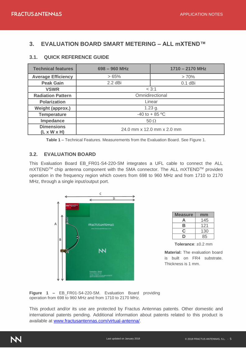
3.2. EVALUATION BOARD
This Evaluation Board EB_FR01-S4-220-SM integrates a UFL cable to connect the ALL
mXTENDTM chip antenna component with the SMA connector. The ALL mXTENDTM provides
operation in the frequency region which covers from 698 to 960 MHz and from 1710 to 2170
MHz, through a single input/output port.
Measure mm
A 145
B 121
C 130
D 85
Tolerance: ±0.2 mm
Material: The evaluation board
is built on FR4 substrate.
Thickness is 1 mm.
Figure 1 – EB_FR01-S4-220-SM. Evaluation Board providing operation from 698 to 960 MHz and from 1710 to 2170 MHz.
This product and/or its use are protected by Fractus Antennas patents. Other domestic and
international patents pending. Additional information about patents related to this product is
available at www.fractusantennas.com/virtual-antenna/.
A
B
C
D
APPLICATION NOTES
Last updated on January 2018 © 2018 FRACTUS ANTENNAS, S.L. - 6
3.3. MATCHING NETWORK
The specs of a Fractus Antennas standard product are measured in an Evaluation Board,
where an ideal case is created. However, when incorporating into real designs, nearby
components such as LCD’s, batteries, covers and connectors may affect the antenna
performance. For this reason, placing pads compatible with 0402 and 0603 SMD components
for a matching network as close as possible to the feeding point is highly recommended. Create
this matching network in the ground plane area rather than the clearance area – this will provide
a degree of freedom for tuning the ALL mXTENDTM antenna component once the design is
finished, taking into account all elements of the system (batteries, displays, covers, etc.).
Please notice that different devices with different ground planes and different components
nearby the ALL mXTENDTM antenna component may require a different matching networks. To
ensure optimal results, the use of high Q and tight tolerance components is highly
recommended (Murata components).
If you need assistance please contact [email protected] for more information related
to our chip antenna component matching service.
698 – 960 MHz and 1710 – 2170 MHz
Value Part Number
12 nH LQW18AN12NG10
1.4 pF GJM1555C1H1R4WB01
10 nH LQW18AN10NG10
2.6 pF GJM1555C1H2R6WB01
1.4 pF GJM1555C1H1R4WB01
Figure 2 – Matching Network implemented in the Evaluation Board (Figure 1).
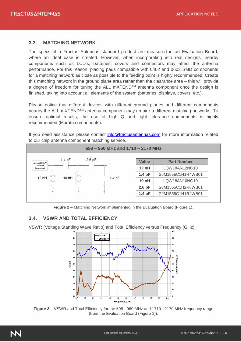
3.4. VSWR AND TOTAL EFFICIENCY
VSWR (Voltage Standing Wave Ratio) and Total Efficiency versus Frequency (GHz).
Figure 3 – VSWR and Total Efficiency for the 698 - 960 MHz and 1710 - 2170 MHz frequency range
(from the Evaluation Board (Figure 1)).
APPLICATION NOTES
Last updated on January 2018 © 2018 FRACTUS ANTENNAS, S.L. - 7
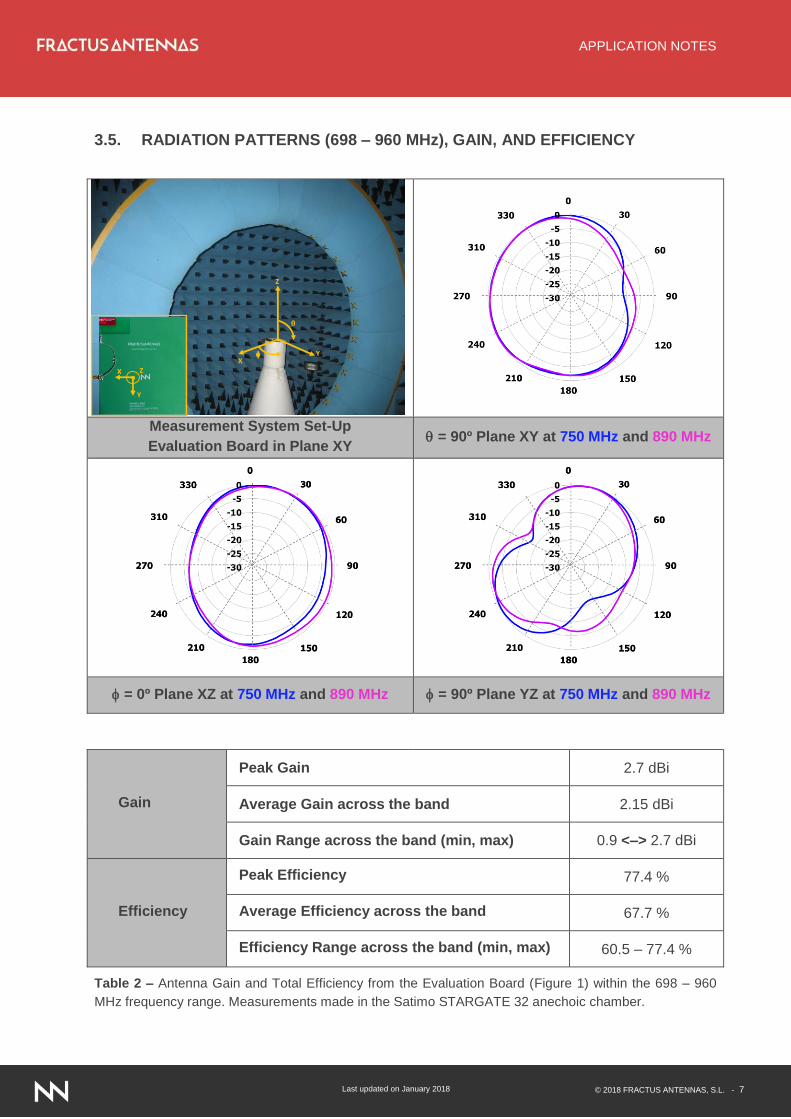
3.5. RADIATION PATTERNS (698 – 960 MHz), GAIN, AND EFFICIENCY
Measurement System Set-Up
Evaluation Board in Plane XY = 90º Plane XY at 750 MHz and 890 MHz
= 0º Plane XZ at 750 MHz and 890 MHz = 90º Plane YZ at 750 MHz and 890 MHz
Gain
Peak Gain 2.7 dBi
Average Gain across the band 2.15 dBi
Gain Range across the band (min, max) 0.9 <–> 2.7 dBi
Efficiency
Peak Efficiency 77.4 %
Average Efficiency across the band 67.7 %
Efficiency Range across the band (min, max) 60.5 – 77.4 %
Table 2 – Antenna Gain and Total Efficiency from the Evaluation Board (Figure 1) within the 698 – 960
MHz frequency range. Measurements made in the Satimo STARGATE 32 anechoic chamber.
XY
Z
θ
X
Y
Z
APPLICATION NOTES
Last updated on January 2018 © 2018 FRACTUS ANTENNAS, S.L. - 8
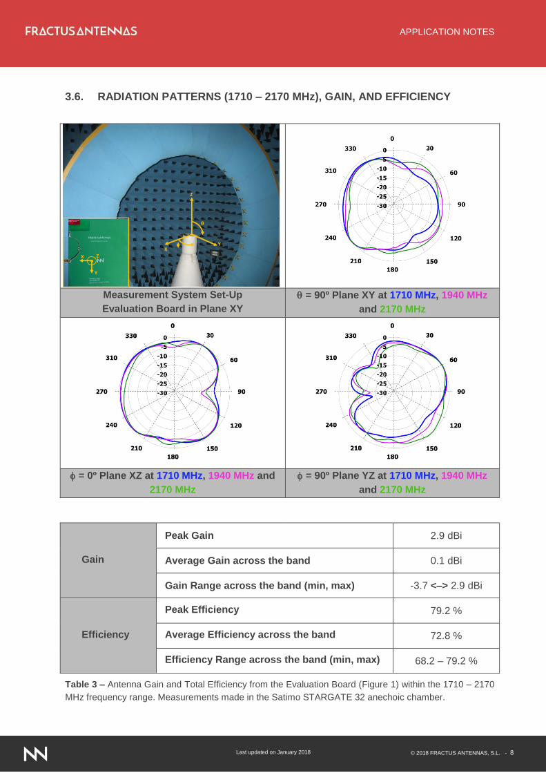
3.6. RADIATION PATTERNS (1710 – 2170 MHz), GAIN, AND EFFICIENCY
Measurement System Set-Up
Evaluation Board in Plane XY
= 90º Plane XY at 1710 MHz, 1940 MHz
and 2170 MHz
= 0º Plane XZ at 1710 MHz, 1940 MHz and
2170 MHz
= 90º Plane YZ at 1710 MHz, 1940 MHz
and 2170 MHz
Gain
Peak Gain 2.9 dBi
Average Gain across the band 0.1 dBi
Gain Range across the band (min, max) -3.7 <–> 2.9 dBi
Efficiency
Peak Efficiency 79.2 %
Average Efficiency across the band 72.8 %
Efficiency Range across the band (min, max) 68.2 – 79.2 %
Table 3 – Antenna Gain and Total Efficiency from the Evaluation Board (Figure 1) within the 1710 – 2170
MHz frequency range. Measurements made in the Satimo STARGATE 32 anechoic chamber.
XY
Z
θ
X
Y
Z
APPLICATION NOTES
Last updated on January 2018 © 2018 FRACTUS ANTENNAS, S.L. - 9
4. EVALUATION BOARD SMART METERING – RUN mXTEND™
4.1. QUICK REFERENCE GUIDE
Technical features 824 – 960 MHz 1710 – 2170 MHz
Average Efficiency > 70% > 65%
Peak Gain -5.7 dBi -0.7 dBi
VSWR < 3:1
Radiation Pattern Omnidirectional
Polarization Linear
Weight (approx.) 0.19 g.
Temperature -40 to + 85 ºC
Impedance 50
Dimensions (L x W x H)
12.0 mm x 3.0 mm x 2.4 mm
Table 4 – Technical Features. Measurements from the Evaluation Board. See Figure 4.
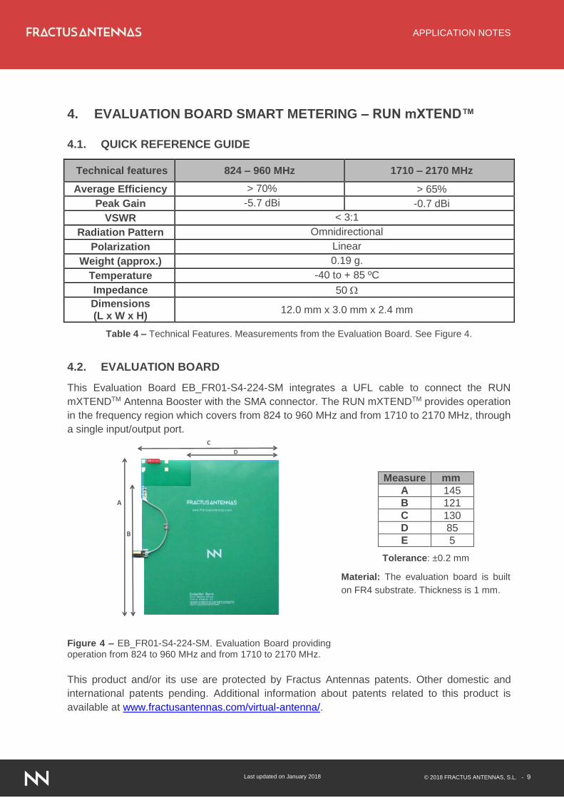
4.2. EVALUATION BOARD
This Evaluation Board EB_FR01-S4-224-SM integrates a UFL cable to connect the RUN
mXTENDTM Antenna Booster with the SMA connector. The RUN mXTENDTM provides operation
in the frequency region which covers from 824 to 960 MHz and from 1710 to 2170 MHz, through
a single input/output port.
Measure mm
A 145
B 121
C 130
D 85
E 5
Tolerance: ±0.2 mm
Material: The evaluation board is built
on FR4 substrate. Thickness is 1 mm.
Figure 4 – EB_FR01-S4-224-SM. Evaluation Board providing operation from 824 to 960 MHz and from 1710 to 2170 MHz.
This product and/or its use are protected by Fractus Antennas patents. Other domestic and
international patents pending. Additional information about patents related to this product is
available at www.fractusantennas.com/virtual-antenna/.
C
A
B
D
APPLICATION NOTES
Last updated on January 2018 © 2018 FRACTUS ANTENNAS, S.L. - 10
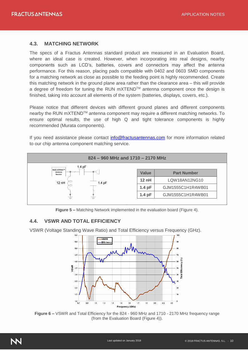
4.3. MATCHING NETWORK
The specs of a Fractus Antennas standard product are measured in an Evaluation Board,
where an ideal case is created. However, when incorporating into real designs, nearby
components such as LCD’s, batteries, covers and connectors may affect the antenna
performance. For this reason, placing pads compatible with 0402 and 0603 SMD components
for a matching network as close as possible to the feeding point is highly recommended. Create
this matching network in the ground plane area rather than the clearance area – this will provide
a degree of freedom for tuning the RUN mXTENDTM antenna component once the design is
finished, taking into account all elements of the system (batteries, displays, covers, etc.).
Please notice that different devices with different ground planes and different components
nearby the RUN mXTENDTM antenna component may require a different matching networks. To
ensure optimal results, the use of high Q and tight tolerance components is highly
recommended (Murata components).
If you need assistance please contact [email protected] for more information related
to our chip antenna component matching service.
824 – 960 MHz and 1710 – 2170 MHz
Value Part Number
12 nH LQW18AN12NG10
1.4 pF GJM1555C1H1R4WB01
1.4 pF GJM1555C1H1R4WB01
Figure 5 – Matching Network implemented in the evaluation board (Figure 4).
4.4. VSWR AND TOTAL EFFICIENCY
VSWR (Voltage Standing Wave Ratio) and Total Efficiency versus Frequency (GHz).
Figure 6 – VSWR and Total Efficiency for the 824 - 960 MHz and 1710 - 2170 MHz frequency range
(from the Evaluation Board (Figure 4)).
APPLICATION NOTES
Last updated on January 2018 © 2018 FRACTUS ANTENNAS, S.L. - 11
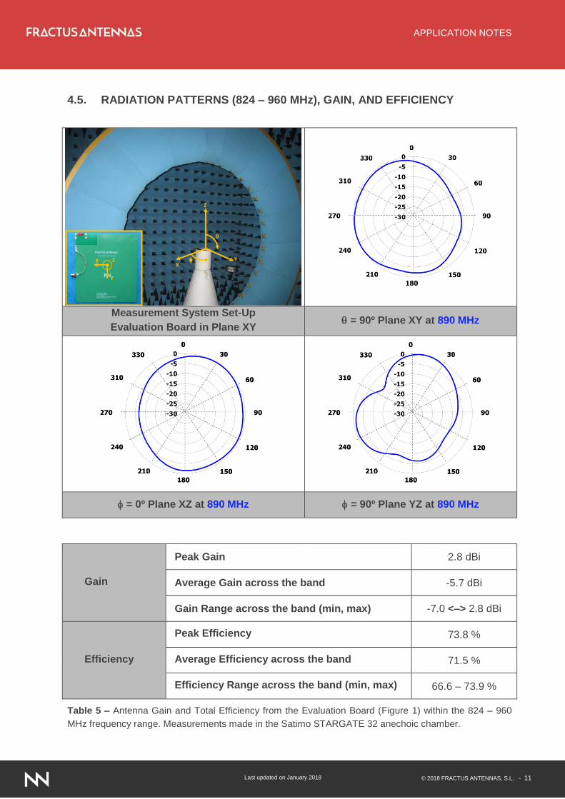
4.5. RADIATION PATTERNS (824 – 960 MHz), GAIN, AND EFFICIENCY
Measurement System Set-Up
Evaluation Board in Plane XY = 90º Plane XY at 890 MHz
= 0º Plane XZ at 890 MHz = 90º Plane YZ at 890 MHz
Gain
Peak Gain 2.8 dBi
Average Gain across the band -5.7 dBi
Gain Range across the band (min, max) -7.0 <–> 2.8 dBi
Efficiency
Peak Efficiency 73.8 %
Average Efficiency across the band 71.5 %
Efficiency Range across the band (min, max) 66.6 – 73.9 %
Table 5 – Antenna Gain and Total Efficiency from the Evaluation Board (Figure 1) within the 824 – 960
MHz frequency range. Measurements made in the Satimo STARGATE 32 anechoic chamber.
XY
Z
θ
X
Y
Z
APPLICATION NOTES
Last updated on January 2018 © 2018 FRACTUS ANTENNAS, S.L. - 12
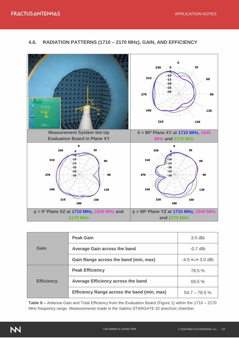
4.6. RADIATION PATTERNS (1710 – 2170 MHz), GAIN, AND EFFICIENCY
Measurement System Set-Up
Evaluation Board in Plane XY
= 90º Plane XY at 1710 MHz, 1940
MHz and 2170 MHz
= 0º Plane XZ at 1710 MHz, 1940 MHz and
2170 MHz
= 90º Plane YZ at 1710 MHz, 1940 MHz
and 2170 MHz
Gain
Peak Gain 3.0 dBi
Average Gain across the band -0.7 dBi
Gain Range across the band (min, max) -4.5 <–> 3.0 dBi
Efficiency
Peak Efficiency 78.5 %
Average Efficiency across the band 69.5 %
Efficiency Range across the band (min, max) 54.7 – 78.5 %
Table 6 – Antenna Gain and Total Efficiency from the Evaluation Board (Figure 1) within the 1710 – 2170
MHz frequency range. Measurements made in the Satimo STARGATE 32 anechoic chamber.
XY
Z
θ
X
Y
Z