Embed Size (px)
Citation preview
s
SIMOVERT Master DrivesEinspeise-EinheitBauform H und KCommon RectifierSizes H and K
BetriebsanleitungOperating Instructions
Ausgabe / Edition: F Bestell-Nr. / Order-No.: 6SE7087-6AK85-0AA0

General 06.01
© Siemens AG 1994 All rights reserved
These Operating Instructions are available in the following languages:
Language French Spanish Italian
Order No.: 6SE7087-7AK85-0AA0 6SE7087-8AK85-0AA0 6SE7087-2AK85-0AA0
Converter software version:
At the time these operating instructions was printed, the infeed and regenerative feedback units were supplied
from the factory with software version 4.5.
These operating instructions basically also apply to other software versions.
Older software versions: It is possible that some parameters might not exist (i.e. that the function they apply todoes not exist) or that some parameters might have a restricted setting range.However, this is generally marked in the parameter list where it applies.
Newer software versions: It is possible that additional parameters might exist on the common rectifier units (i.e.that there are also additional functions that are not described in these operatinginstructions) or that some parameters might have an extended setting range. Leavesuch parameters in their factory setting and on no account set any values that are notdescribed in these operating instructions!
You can order the latest software version (EPROM) under MLFB No.: 6SW1701-0DA14.
The reproduction, transmission or use of this document or contents isnot permitted without express written authority. Offenders will be liablefor damages. All rights, including rights created by patent grant orregistration of a utility model or design, are reserved.
We have checked that the contents of this publication agree with thehardware and software described herein. Nonetheless, differencesmight exist and therefore we cannot guarantee that they are completelyidentical. The information given in this publication is reviewed at regularintervals and any corrections that might be necessary are made in thesubsequent printings. Suggestions for improvement are welcome at alltimes. SIMOVERT ® is a registered trademark of Siemens

06.01 Contents
Siemens AG 6SE7087-6AK85-0AA0 ENGLISH 0-3Common Rectifier Operating Instructions
ENGLISH
ContentsPage
0 Definitions .................................................................................................................. 0-9
1 Description ................................................................................................................. 1-1
1.1 Application ....................................................................................................................... 1-1
1.2 Principle of operation ....................................................................................................... 1-1
2 Transport, Unpacking and Assembly ............................................................. 2-1
2.1 Transport, unpacking ....................................................................................................... 2-1
2.2 Storage ............................................................................................................................ 2-1
2.3 Assembly ......................................................................................................................... 2-1
2.4 Dimension drawings ........................................................................................................ 2-3
3 Connection ................................................................................................................. 3-1
3.1 Power connections .......................................................................................................... 3-2
3.1.1 Short-circuit withstand capability ..................................................................................... 3-6
3.2 Power supply and main contactor .................................................................................... 3-7
3.3 Control terminal block and serial interface ...................................................................... 3-8
3.3.1 Connectors for the control terminal block ........................................................................ 3-8
3.3.2 Connecting the control leads ........................................................................................... 3-8
3.3.3 Terminals and setting elements on the CUR (A10) module ............................................ 3-9
3.3.4 Connecting-up the parameterizing unit (PMU) ................................................................ 3-11
3.4 Measures for keeping to RFI suppression regulations .................................................... 3-12
3.5 Single-line diagrams with suggested circuit arrangements ............................................. 3-13
3.6 Power sections ................................................................................................................ 3-15
3.7 Parallel connection of parallel unit(s), size K ................................................................... 3-18
3.7.1 Single-line diagram with suggested circuit arrangement for parallel connection ............. 3-21
3.8 12-pulse mode (only possible with the optional RS485 interface) ................................... 3-22
3.8.1 General information on 12-pulse mode, application ........................................................ 3-22
3.8.2 Hardware requirements, configuration of the power sections ......................................... 3-23
3.8.3 Parameterization for 12-pulse mode ............................................................................... 3-24
3.8.4 Control/status word for 12-pulse mode (r599) and control word 2, bit 23 ....................... 3-26
3.8.5 Start-up with 12-pulse mode ............................................................................................ 3-27
3.8.6 Redundancy mode ........................................................................................................... 3-29
3.8.7 RS485 interface cable for the Peer-to-Peer link on SST2 ............................................... 3-30

Contents 06.01
0-4 ENGLISH Siemens AG 6SE7087-6AK85-0AA0Common Rectifier Operating Instructions
Page
4 Start-Up ........................................................................................................................... 4-1
4.1 Introduction and handling start-up ................................................................................... 4-1
4.1.1 Handling the start-up instructions .................................................................................... 4-1
4.1.2 General explanation of the terminology and functional scope of the common rectifier ... 4-1
4.2 Initial start-up ................................................................................................................... 4-4
4.2.1 Preparatory measures ..................................................................................................... 4-4
4.2.2 Parameterization "Standard application“ ......................................................................... 4-5
4.2.3 Parameterization for "Expert application“ ........................................................................ 4-7
4.2.5 Simple application examples for connecting process data with connection assignment . 4-9
4.3 Start-up aids .................................................................................................................... 4-10
4.3.1 Process data .................................................................................................................... 4-10
4.3.1.1 Control word (control word 1 and control word 2) ............................................................ 4-10
4.3.1.1.1 Introduction and application example .............................................................................. 4-10
4.3.1.1.2 Overview of the control word (control word 1 and control word 2) ................................... 4-12
4.3.1.1.3 Selecting the source for control word 1 (bits 0-7) ............................................................ 4-13
4.3.1.1.4 Selecting the source for control word 1 (bits 8-15) .......................................................... 4-14
4.3.1.1.5 Selecting the source for control word 2 (bits 16-23) ........................................................ 4-15
4.3.1.1.6 Selecting the source for control word 2 (bits 24-31) ........................................................ 4-16
4.3.1.1.7 Significance of control word- (1 and 2) commands ......................................................... 4-17
4.3.1.2 Status word (status word 1 and status word 2) ................................................................ 4-22
4.3.1.2.1 Introduction and application example .............................................................................. 4-22
4.3.1.2.2 Overview of the status word (status word 1 and status word 2) ...................................... 4-23
4.3.1.2.3 Selecting the destinations for the status word (bits 0 - 31) .............................................. 4-24
4.3.1.2.4 Significance of the status word messages ...................................................................... 4-25
4.3.1.3 Setpoints .......................................................................................................................... 4-27
4.3.1.4 Actual values ................................................................................................................... 4-28
4.3.2 Binary inputs .................................................................................................................... 4-29
4.3.3 Binary outputs .................................................................................................................. 4-29
4.3.5 Analog output ................................................................................................................... 4-30
4.3.6 Serial interfaces ............................................................................................................... 4-33
4.3.6.1.1 Basic converter interface SST1 ....................................................................................... 4-33
4.3.6.1.2 Basic converter interface SST2 (A2-X117), see Section 9.6, Options ............................ 4-33
4.3.6.2 Dual-port RAM (DPR for SCB, CB, TB) ........................................................................... 4-33
4.3.9 Function selection (P052) ................................................................................................ 4-34
4.3.9.1 Generating the factory setting (P052 = 1 or P970 = 0) ................................................. 4-34
4.3.9.2 Initialization (MLFB setting) (P052 = 2) ......................................................................... 4-36
4.3.9.3 Download or upread (P052 = 3) .................................................................................... 4-37
4.3.9.4 Hardware configuration (P052 = 4) ............................................................................... 4-38
4.3.9.5 Drive setting (P052 = 5) ................................................................................................ 4-39
4.3.9.6 Form DC link (P052 = 20) ............................................................................................. 4-40

06.01 Contents
Siemens AG 6SE7087-6AK85-0AA0 ENGLISH 0-5Common Rectifier Operating Instructions
Page
4.3.9.7 Circuit identification (P052 = 21) ................................................................................... 4-41
4.3.9.8 Display modified parameters (P052 = 22) .................................................................... 4-43
4.3.10 Functions ......................................................................................................................... 4-43
4.3.10.1 WEA (automatic restart) ................................................................................................. 4-43
4.3.10.2 Externally requested and current-dependent Ud reduction ............................................. 4-45
4.4 Function diagrams ........................................................................................................... 4-46
4.5 Starting up optional supplementary boards ..................................................................... 4-51
4.5.1 Procedure for starting up technology boards (T100, T300, T400) .................................. 4-51
4.5.2 Sequence of operations for starting up PROFIBUS boards (CBP2) ............................... 4-52
4.5.2.1 Mechanisms for processing parameters via the PROFIBUS .......................................... 4-54
4.5.2.2 Diagnostic tools ............................................................................................................... 4-55
4.5.3 Sequence of operations for starting up CAN bus boards (CBC) ..................................... 4-59
4.5.3.1 Description of CBC with CAN Layer 2 ............................................................................. 4-60
4.5.3.2 Diagnostic tools ............................................................................................................... 4-64
4.5.4 Sequence of operations for starting up the serial I/O board SCB1 .................................. 4-67
4.5.4.1 SCB1 as master for SCI1 and SCI2 ................................................................................. 4-68
4.5.4.2 SCB1 as peer-to-peer interface........................................................................................ 4-69
4.5.4.3 Diagnostic tools ............................................................................................................... 4-69
4.5.5 Sequence of operations for starting up the board SCB2 ................................................. 4-70
4.5.6 Structure of request/response telegrams ........................................................................ 4-71
5 Parameter List .......................................................................................................... 5-1
5.1 Operation display ............................................................................................................. 5-3
5.2 General observation parameters ..................................................................................... 5-4
5.3 General parameters ......................................................................................................... 5-6
5.4 Drive data ........................................................................................................................ 5-8
5.5 Hardware configuration ................................................................................................... 5-10
5.6 Data of the DC link .......................................................................................................... 5-11
5.7 Control ............................................................................................................................. 5-12
5.8 Convenience functions .................................................................................................... 5-15
5.9 Setpoint channel .............................................................................................................. 5-17
5.10 Control and status word ................................................................................................... 5-18
5.11 Analog input/output .......................................................................................................... 5-27
5.12 Communications .............................................................................................................. 5-29
5.13 Diagnostics ...................................................................................................................... 5-34
5.14 Modulator ......................................................................................................................... 5-36
5.15 Factory parameters ......................................................................................................... 5-37
5.16 Profile parameters ........................................................................................................... 5-38

Contents 06.01
0-6 ENGLISH Siemens AG 6SE7087-6AK85-0AA0Common Rectifier Operating Instructions
Page
6 Operator Control ...................................................................................................... 6-1
6.1 Operator control elements ............................................................................................... 6-1
6.2 Displays 8.8.8.8. ............................................................................................................ 6-2
6.3 Structure .......................................................................................................................... 6-3
7 Fault and Alarm Messages .................................................................................. 7-1
7.1 Fault messages ............................................................................................................... 7-1
7.2 Alarm messages .............................................................................................................. 7-9
8 Maintenance .............................................................................................................. 8-1
8-1 Maintenance recommendations ...................................................................................... 8-1
8.2 Replacing components .................................................................................................... 8-2
8.2.1 Replacing the fan ............................................................................................................. 8-2
8.2.2 Replacing modules .......................................................................................................... 8-3
8.2.3 Power interface module spare parts ................................................................................ 8-6
8.2.4 Replacing thyristor blocks ................................................................................................ 8-8
8.2.4.1 Disassembling the thyristor blocks for size H .................................................................. 8-8
8.2.4.2 Disassembling the thyristor blocks for size K .................................................................. 8-9
9 Options ........................................................................................................................ 9-1
9.1 Options which can be integrated into the electronics box ................................................ 9-1
9.2 Interface boards ............................................................................................................... 9-3
9.3 Power Supply ................................................................................................................... 9-3
9.4 Operator control panel OP1S .......................................................................................... 9-4
9.5 RS485 interface (PTP1) ................................................................................................... 9-5
9.5.1 Order designation ............................................................................................................ 9-6
9.5.2 Assembly ......................................................................................................................... 9-6
9.5.3 Function and terminal description .................................................................................... 9-6
9.5.4 Parameterization .............................................................................................................. 9-7
9.6 SIMOVIS .......................................................................................................................... 9-7
10 Spare Parts ................................................................................................................ 10-1
11 Blank
12 Logbook ...................................................................................................................... 12-1
13 Environmental Compatibility .............................................................................. 13-1

06.01 Contents
Siemens AG 6SE7087-6AK85-0AA0 ENGLISH 0-7Common Rectifier Operating Instructions
Page
14 Technical Data .......................................................................................................... 14-1
14-1 Power reduction at increased coolant temperature ......................................................... 14-5
14.2 Power reduction at altitudes > 1000m above MSL .......................................................... 14-5
14.3 Applied standards ............................................................................................................ 14-6

Contents 06.01
0-8 ENGLISH Siemens AG 6SE7087-6AK85-0AA0Common Rectifier Operating Instructions

06.01 Definitions
Siemens AG 6SE7087-6AK85-0AA0 ENGLISH 0-9Common Rectifier Operating Instructions
0 Definitions
• QUALIFIED PERSONNEL
For the purpose of this Instruction Manual and product labels, a "Qualified person" is someonewho is familiar with the installation, construction and operation of the equipment and the hazardsinvolved. He or she must have the following qualifications:
1. Trained and authorized to energize, de-energize, clear, ground and tag circuits andequipment in accordance with established safety procedures.
2. Trained in the proper care and use of protective equipment in accordance with establishedsafety procedures.
3. Trained in rendering first aid.
• ς DANGER
indicates an imminently hazardous situation which, if not avoided, will result in death or seriousinjury.
• ς WARNING
indicates a potentially hazardous situation which, if not avoided, could result in death or seriousinjury.
• ς CAUTION
used with the safety alert symbol indicates a potentially hazardous situation which, if notavoided, may result in minor or moderata injury.
• CAUTION
used without the safety alert symbol indicates a potentially hazardous situation which, if notavoided, may result in property demage.
• NOTICE
NOTICE used without the safety alert symbol indicates a potentially situation which, if notavoided, may result in an undesireable result or state.
NOTE
For reasons of clarity, these operating instructions do not contain all details of all types of the product and canalso not take into account every conceivable installation, operation or maintenance circumstances.
You can consult your local Siemens branch if you should require further information or if particular problemoccur that are not dealt with in adequate detail in the operating instructions.
Attention is also drawn to the fact that the contents of this instruction manual shall not become part of ormodify any prior or existing agreement, commitment or legal relationship. The sales contract, which alsocontains the complete and solely valid warranty stipulations, contains the entire obligations of Siemens. Thesecontractual warranty stipulations are neither extended nor limited by the statements given in instructions anddocumentation.

Definitions 06.01
0-10 ENGLISH Siemens AG 6SE7087-6AK85-0AA0Common Rectifier Operating Instructions
CAUTION
Electrostatically Sensitive Devices (ESDs)
The equipment contains electrostatically sensitive devices. These components may be destroyed very easilyby improper handling. Please observe the following notes if you nevertheless have to work with electronicmodules:
♦ Electronic modules should only be touched if absolutely necessary to carry out work on them.
♦ If modules nevertheless have to be touched, you must discharge your own body directly beforehand (this isbest done by touching an earthed conductive object such as the PE contact of a socket).
♦ Modules must not come into contact with highly insulating materials − e.g. plastic films, insulating desktopsor synthetic fibber clothing items.
♦ Modules must only be placed on conductive surfaces.
♦ When soldering modules, the tip of the soldering iron must be earthed.
♦ Modules and components must only be stored or dispatched in conductive packaging (e.g. metallizedplastic boxes or metal tins).
♦ If packagings are not conductive, modules must be placed in a conductive envelopment prior to packaging.In this case, use can be made of conductive foam rubber or domestic aluminum foil, for example.
The necessary protective measures for ESDs are elucidated once again in the following figure:
a = conductive floor d = ESD coat
b = ESD desk e = ESD armband
c = ESD shoes f = earthing terminal on cabinets
a
b
e
d
f f f
d
ac
e
d
f f
b
ca
Sitting position Standing position Standing / Sitting position
WARNING
When operating electrical equipment, certain parts of such equipment are inevitably live.
Owing to the dc link capacitors, hazardous voltages are present on the equipment up to5 min. after deenergization (power terminal and electronic power supply). This is why it isnot permitted to open the housing until after waiting for 5 minutes.
Non-observance of warning notices can result in death, severe personal injury orconsiderable property damage.
Such personnel must be thoroughly acquainted with all warnings and maintenanceactivities.
Perfect and safe operation of the equipment requires proper transport, expert storage,installation and assembly and cautious operation and maintenance.

06.01 Definitions
Siemens AG 6SE7087-6AK85-0AA0 ENGLISH 0-11Common Rectifier Operating Instructions

Definitions 06.01
0-12 ENGLISH Siemens AG 6SE7087-6AK85-0AA0Common Rectifier Operating Instructions

06.01 Description
Siemens AG 6SE7087-6AK85-0AA0 ENGLISH 1-1Common Rectifier Operating Instructions
1 Description
1.1 Application
The SIMOVERT Master Drive power supply units type 6SE70 are power electronic units of compact design.They function as a DC power supply unit for the SIMOVERT Master Drive inverter series type 6SE70. The powersupply unit generates a DC voltage of fixed amplitude (depending on the mode of operation and the voltagetolerance) from a three-phase AC power supply system.
One or more inverters and braking DC choppers can be connected to the output of the unit. The sum of therated currents of the installed inverters may not exceed the rated current of the power supply unit. On planningthe installation it must be ensured that the sum of the instantaneous load compensation currents at no timeexceeds the rated current of the power supply unit. Feedback of energy to the power supply system is notpossible.
The output current can be increased by connecting power sections of size K in parallel. Up to 2 parallel units ofthe same rated current can be connected in parallel with one basic unit (see Section 3.7 for further details onparallel connection)
You can make technological adaptations and expansions over a defined interface in the control section.
Harmonic loading on the supply network can be reduced by coupling 2 units for "12-pulse mode" (for furtherdetails on "12-pulse mode", see Section 3.8).
1.2 Principle of operation
The power section of the power supply unit comprises a six-pulse thyristor bridge for controlled rectification ofthe three-phase AC power supply. Control of the link circuit voltage is effected by means of a digital controllermodule with microprocessor.
A 24V external supply is required for operating the units (see Sections 3.5 and 9.3).
The common rectifier is suitable for connecting several inverters to a common DC bus. This permits theexchange of energy between motoring and generating drives, and thus saves energy.
Once the DC link capacitors have been precharged, the inverters are ready for operation.
Start-up of the rectifier unit is carried out via an operator panel on the electronics box. Operation is performed viathe terminal strip or via a serial interface
Optional interfaces and intelligent I/O modules are available in conjunction with programmable controllers andother automation equipment for controlling the common rectifiers.

Description 06.01
1-2 ENGLISH Siemens AG 6SE7087-6AK85-0AA0Common Rectifier Operating Instructions

06.01 Transport, Unpacking and Assembly
Siemens AG 6SE7087-6AK85-0AA0 ENGLISH 2-1Common Rectifier Operating Instructions
2 Transport, Unpacking and Assembly
2.1 Transport and unpacking
The units are packed at the manufacturing works. A product packaging label is attached to the box.
Avoid extreme vibrations and hard impacts during transport, e.g. when lowering the unit.
Pay attention to the notes on the packaging relating to transport, storage and proper handling.
The converter can be installed after unpacking it and checking the consignment for completeness anddamage.
The units are bolted onto pallets with fixing pieces in their usual operating position and packed withcardboard.The packaging may be disposed of in accordance with local cardboard disposal regulations.
You should notify your freight forwarder immediately if you discover any transportation damage.
2.2 Storage
The units must be stored in clean dry rooms. Temperatures between −25 °C (−13 °F) and + 70 °C (158 °F) arepermissible. Temperature fluctuations > 20 K per hour are not permissible.
2.3 Assembly
The following are required for securing size H:
♦ four M8 bolts
♦ four M8 bolts
The following are required for securing size K:
♦ six M8 bolts
♦ dimension drawing (Figure 2.3 for size K)
WARNING
For safe operation of the unit, it is presumed it will be assembled and commissioned byqualified personnel, paying attention to the warning notes given in these operatinginstructions.
Particular note must be taken both of the general and national erection and safetyregulations regarding work on power installations (e.g. VDE) and regulations regarding theproper use of tools and of personal protective equipment.
Non-observance of warning notices can result in death, severe personal injury orconsiderable property damage.
The unit must be protected against the ingress of foreign matter as otherwise properfunctioning and safety will not be guaranteed.

Transport, Unpacking and Assembly 06.01
2-2 ENGLISH Siemens AG 6SE7087-6AK85-0AA0Common Rectifier Operating Instructions
Requirements for the installation site:
Local guidelines and standards must be observed in relation to assembly.
Operating facilities must be dry and dust-free. Air fed in must notcontain any gases, vapors or dusts that are electrically conductive ordetrimental to functioning. Air containing dust must be filtered.
WARNINGDimension cabinet ventilation according to thedissipated power! (Technical data in Chapter 14)
The unit’s ambient climate in operating rooms must not exceed thevalues of code 3K3 as detailed in DIN IEC 721 Part 3-3 /04.90. Areduction of power as detailed in Chapters 14.1 and 14.2 isnecessary in the event of temperatures > 40 °C (104 °F) andaltitudes >1000m. The terminal voltage has to be reduced foraltitudes > 2000m.
Carry out assembly in accordance with the dimension drawings inSection 2.4.
6SE70
Dissipate power
Cooling air ≤ 40 °C (50°C)
Figure 2.1 Installation in control cabinets
WARNING
In the case of units, all plastic covers must be mounted to ensure correct air flow andcooling for the units.

06.01 Transport, Unpacking and Assembly
Siemens AG 6SE7087-6AK85-0AA0 ENGLISH 2-3Common Rectifier Operating Instructions
2.4 Dimension drawings
A1
0
PM
U
X3
00 3)
551
1050
45950
119
270
50
26
50252
250
67
W1
L3V
1L2
U1
L1P
E1
A2
3
130
155
85
22528
5
F11
F14
F13
F16
F15
F12
T1
T2
PE
1
X1
9 5
)
X9
4)
X19 F4
F3 X
27
X29 X
9F
5 F
1 F
2
C/L
+D
/L-
2)
1)
2)
119
61
26
26
C/L
+D
/L-63
508
234
376
9240
40
40
V1
/L2
U1/
L1W
1/L
3
X1
9X
9
50 40
70
PE
2
PE
2
1)
424
6)
7)7)
7)
Opt
ions
Leve
l BLe
vel A
Exh
aust
air
Air
inta
ke
Mou
ntin
g h
oles
for
wa
ll m
ount
ing
with
M8
bolts
Fro
nt v
iew
1) M
ount
ing
hole
for
M1
2 sc
rew
2) M
12 th
rea
d
3) S
cre
en c
onn
ectio
n fo
r ca
ble
s
4) C
onne
ctor
for
24 V
DC
pow
er s
uppl
y
an
d m
ain
cont
acto
r
5) F
an c
onne
ctio
n
6) R
emo
ve tr
ansp
ort
pla
tes
befo
re s
tart
-up
7) F
or c
abi
net i
nsta
llatio
n:
Insu
late
this
pa
rt o
f th
e un
it ag
ain
st t
he
ca
bine
t wa
lls a
nd d
oor
Whe
n th
e un
its a
re in
sta
lled
in c
abin
ets,
it m
ust
be e
nsur
ed t
hat
the
air
inta
ke a
nd
exha
ust
isad
equa
te (
for
air
req
uire
men
ts a
nd in
take
air
tem
pera
ture
, see
Se
ctio
n 14
"T
echn
ical
Dat
a").
No
dis
plac
emen
t of t
he c
ent
re o
f gra
vity
Wei
ght:
refe
r to
Sec
tion
14 (
Tec
hnic
al D
ata)
Dim
ensi
on: m
m
Figure 2.2 Dimension drawing, size H

Transport, Unpacking and Assembly 06.01
2-4 ENGLISH Siemens AG 6SE7087-6AK85-0AA0Common Rectifier Operating Instructions
W1
L3
V1
L2
A1
0
PM
U
X3
00 3)
A2
3
85
400 340 270
130
200
U1
L1
C L+
D L-
PE
1
40
50
40
40
40
310
175
420
555
665
26
26
26
26
PE
1
V1
/L2
W1
/L3
C/L
+D
/L-
U1/L
1
62 50
550
26
87
26
A2
3
45
258
483
708
800
1300
14002)
1)
3)
X1
9 5)
X9
4)
X1
9X
9
PE
2
205
PE
2
50
40
710
1)
6a)
6a)
6a)
6b)
122,5
Opt
ions
Leve
l ALe
vel B
Exh
aust
air
Air
inta
ke
Mou
ntin
g h
ole
s fo
r w
all
mou
ntin
gw
ith M
8 bo
lts
Fro
nt v
iew
Whe
n th
e un
its a
re in
sta
lled in
cab
inet
s,it
mus
t be
ensu
red
tha
t th
e ai
r in
take
an
dex
haus
t is
ade
qua
te (
for
air r
equ
irem
ent
san
d in
take
air
tem
pera
ture
, se
e S
ect
ion
14 "
Tec
hnic
al D
ata
").
No
dis
pla
cem
ent o
f th
e ce
ntr
e o
f g
ravi
ty
Weig
ht: r
efe
r to
Sec
tion 1
4 (T
ech
nic
al D
ata)
Dim
en
sion
: m
m
1) M
ount
ing
hole
for
M12
scre
w
2) M
12 th
read
3) S
cre
en c
onne
ctio
n fo
r ca
ble
s
4) C
onn
ect
or fo
r 2
4 V
DC
po
wer
su
pply
a
nd m
ain
con
tact
or
5) F
an c
onn
ectio
n
6) F
or
cabin
et in
stal
latio
n:
a
) In
sula
te t
his
pa
rt o
f th
e un
it ag
ains
t
the c
abin
et w
alls
and
do
or.
b
) Lo
osen
fix
ing
scr
ews
for
fan
ca
sin
g
(M8
/SW
13)
and li
ft u
p p
last
ic c
ove
r
as
far
as t
he
ca
bine
ttop p
ane
l.
Tig
hte
n sc
rew
s a
gain
.
Figure 2.3 Dimension drawing, size K

06.01 Connection
Siemens AG 6SE7087-6AK85-0AA0 ENGLISH 3-1Common Rectifier Operating instructions
3 Connection
WARNING
The units are operated at high voltages.
Only carry out connection work after disconnecting the voltage!
All work on the unit must only be carried out by qualified persons.
Non-observance of warning notices can result in death, severe personal injury orconsiderable property damage.
Damage or destruction can result if the unit is incorrectly connected.
As the result of the dc link capacitors in the connected SIMOVERT Master Drives, the unitstill contains a hazardous voltage up to 5 min. after isolation. This is why it is only permittedto open the unit after observing an appropriate waiting time.
The power terminals and control terminals may carry a voltage even when the motor is atstandstill.
When working on the open unit, pay attention to the fact that live parts are exposed. Theunit may only be operated with the front covers attached.
The user is responsible for ensuring that the common rectifier, converter, motor and otherunits are installed and connected in accordance with the technical regulations recognized inthe country of installation and other regionally valid regulations. In doing so, particularattention must be paid to cable dimensioning, fusing, earthing, deactivation, isolation andovercurrent protection.
CAUTION
The power cables must be fixed in position mechanically outside the unit.
NOTICE
An external 24 V power supply is required for operation of the units (see Chapters 3.5 and 9.3).
Operational range of the unit: 20 V to 30 V.

Connection 06.01
3-2 ENGLISH Siemens AG 6SE7087-6AK85-0AA0Common Rectifier Operating instructions
3.1 Power connections
C/L+ D/L-
PE2
V1/L2U1/L1 W1/L3
PE1
X9
X19
Mains
Mains fan
DC link(DC output)
1)
1)
PE1
V1/L2 W1/L3
C/L+ D/L-
U1/L1
PE2X9
X19Mains
Mains fan
DC link(DC output)
1)
1)
Figure 3.1 Mains connection size H Figure 3.2 Mains connection size K
1) Due to the press-in nuts, cable lugs or DC rails can only be connected to the terminal rails from the front.
WARNING
The operating coils of contactors and relays that are connected to the same supply networkas the unit or that are located in close proximity of the unit must be connected to over-voltage limiters, e.g. RC circuits.
An RCCB (residual-current-operated circuit-breaker) must not be used to protect therectifier/regenerating unit (DIN VDE 0160).
Voltage is only permitted to be applied to the unit when SIMOVERT Master Drives areconnected. Operation without a connected DC link capacitor is not permitted!
If the DC link terminals are connected incorrectly or short-circuited, the SIMOVERT MasterDrives inverter will be destroyed!
In order to prevent feedback of interference to the power supply system, limit harmonicsand reduce the current ripple, the total inductance of the power system incoming feederconnection (power system inductance including commutating reactor) a total relative short-circuit voltage uk of at least 3% .
Connect the fan power supply to X19.The fan continues to run for about four minutes or until a certain cooling elementtemperature threshold is undershot (provided its power supply is connected) after the unithas been switched off, following fault messages, on canceling the enable signal and afterisolating the system supply connection.Despite switching the voltage off at the power terminals, a voltage may still exist onterminal X19 due to the external fan supply.
06.01 Connection
Siemens AG 6SE7087-6AK85-0AA0 ENGLISH 3-3Common Rectifier Operating instructions
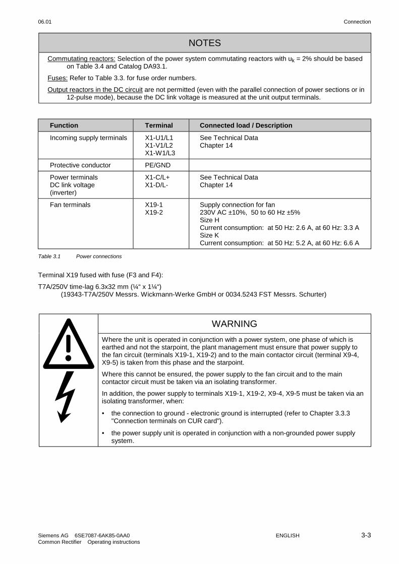
NOTES
Commutating reactors: Selection of the power system commutating reactors with uk = 2% should be basedon Table 3.4 and Catalog DA93.1.
Fuses: Refer to Table 3.3. for fuse order numbers.
Output reactors in the DC circuit are not permitted (even with the parallel connection of power sections or in12-pulse mode), because the DC link voltage is measured at the unit output terminals.
Function Terminal Connected load / Description
Incoming supply terminals X1-U1/L1X1-V1/L2X1-W1/L3
See Technical DataChapter 14
Protective conductor PE/GND
Power terminalsDC link voltage(inverter)
X1-C/L+X1-D/L-
See Technical DataChapter 14
Fan terminals X19-1X19-2
Supply connection for fan230V AC ±10%, 50 to 60 Hz ±5%Size HCurrent consumption: at 50 Hz: 2.6 A, at 60 Hz: 3.3 ASize KCurrent consumption: at 50 Hz: 5.2 A, at 60 Hz: 6.6 A
Table 3.1 Power connections
Terminal X19 fused with fuse (F3 and F4):
T7A/250V time-lag 6.3x32 mm (¼“ x 1¼“)(19343-T7A/250V Messrs. Wickmann-Werke GmbH or 0034.5243 FST Messrs. Schurter)
WARNING
Where the unit is operated in conjunction with a power system, one phase of which isearthed and not the starpoint, the plant management must ensure that power supply tothe fan circuit (terminals X19-1, X19-2) and to the main contactor circuit (terminal X9-4,X9-5) is taken from this phase and the starpoint.
Where this cannot be ensured, the power supply to the fan circuit and to the maincontactor circuit must be taken via an isolating transformer.
In addition, the power supply to terminals X19-1, X19-2, X9-4, X9-5 must be taken via anisolating transformer, when:
• the connection to ground - electronic ground is interrupted (refer to Chapter 3.3.3"Connection terminals on CUR card").
• the power supply unit is operated in conjunction with a non-grounded power supplysystem.

Connection 06.01
3-4 ENGLISH Siemens AG 6SE7087-6AK85-0AA0Common Rectifier Operating instructions
The units are designed for permanent connection to the system in keeping with DIN VDE 0160 Section 6.5.2.1.
Protective conductor connection: Min. cross-sectional area 10 mm2 (see Table 3.2).
The conductor cross-sectional areas listed in Table 3.2 are maximum connectable cross-sections. The data isgiven for multicore cable. The cross-sectional areas actually wired and the associated connection elements mustbe selected according to the currently valid standards - e.g. DIN VDE 100 Part 523, DIN VDE 0276 Part 1000,UL, CSA, ....
Mains DC link Protectiveconductor
Unit Order No. Rated input
ConductorU1/L1, V1/L2, W1/L3
ConductorC/L+, D/L-
ConductorPE
voltage current max. max. max. max.
6SE70 (V) (A) mm2 1) AWG 2) mm2 1) AWG 2) mm2 1) AWG 2)
38-2EH85-0AA0 380 to 480 710 K 4x300S 100x10
4x600 K 4x300S 60x10
4x600 K 4x300S 100x10
4x600
41-0EH85-0AA0 380 to 480 888 K 4x300S 100x10
4x600 K 4x300S 60x10
4x600 K 4x300S 100x10
4x600
41-3EK85-0AA0 380 to 480 1156 K 4x300S 100x10
4x600 K 6x300S 100x10
6x600 K 4x300S 100x10
4x600
41-8EK85-0AA0 380 to 480 1542 K 4x300S 100x10
4x600 K 6x300S 100x10
6x600 K 4x300S 100x10
4x600
37-7FH85-0AA0 500 to 600 671 K 4x300S 100x10
4x600 K 4x300S 60x10
4x600 K 4x300S 100x10
4x600
41-0FH85-0AA0 500 to 600 888 K 4x300S 100x10
4x600 K 4x300S 60x10
4x600 K 4x300S 100x10
4x600
41-3FK85-0AA0 500 to 600 1119 K 4x300S 100x10
4x600 K 6x300S 100x10
6x600 K 4x300S 100x10
4x600
41-5FK85-0AA0 500 to 600 1306 K 4x300S 100x10
4x600 K 6x300S 100x10
6x600 K 4x300S 100x10
4x600
41-8FK85-0AA0 500 to 600 1633 K 4x300S 100x10
4x600 K 6x300S 100x10
6x600 K 4x300S 100x10
4x600
37-7HH85-0AA0 660 to 690 671 K 4x300S 100x10
4x600 K 4x300S 60x10
4x600 K 4x300S 100x10
4x600
41-0HH85-0AA0 660 to 690 888 K 4x300S 100x10
4x600 K 4x300S 60x10
4x600 K 4x300S 100x10
4x600
41-3HK85-0AA0 660 to 690 1119 K 4x300S 100x10
4x600 K 6x300S 100x10
6x600 K 4x300S 100x10
4x600
41-5HK85-0AA0 660 to 690 1306 K 4x300S 100x10
4x600 K 6x300S 100x10
6x600 K 4x300S 100x10
4x600
41-8HK85-0AA0 660 to 690 1633 K 4x300S 100x10
4x600 K 6x300S 100x10
6x600 K 4x300S 100x10
4x600
Table 3.2 Connection cross-sections
1) C=Cable, R=Rail2) American Wire Gauge

06.01 Connection
Siemens AG 6SE7087-6AK85-0AA0 ENGLISH 3-5Common Rectifier Operating instructions
Unit Built-in branch fuses F11 to F16
Order No. Siemens SITOR BussmannUS standard
6SE70 A Type A Type
38-2EH85-0AA0 630 3NE3336 700 170M4717
41-0EH85-0AA0 800 3NE3338-8 900 170M5715
37-7FH85-0AA0 560 3NE3335 630 170M5696
41-0FH85-0AA0 800 3NE3338-8 900 170M5699
37-7HH85-0AA0 560 3NE3335 630 170M5696
41-0HH85-0AA0 800 3NE3338-8 900 170M5699
Built-in branch fuses F111 to F162
41-3EK85-0AA0 630 3NE3336
41-8EK85-0AA0 800 3NE3338-8
41-3FK85-0AA0 560 3NE3335 630 170M5696
41-5FK85-0AA0 710 3NE3337-8 630 170M5696
41-8FK85-0AA0 800 3NE3338-8 800 170M5698
41-3HK85-0AA0 560 3NE3335 630 170M5696
41-5HK85-0AA0 710 3NE3337-8 630 170M5696
41-8HK85-0AA0 800 3NE3338-8 800 170M5698
Table 3.3 Built-in branch fuses
Table 3.3: Semiconductor protection only, lines are not reliably protected.
CAUTION
With these units, no external semiconductor protection is needed.
Line protection must be ensured for all device types by assigning a suitable line protection element (e.g. fuse,line protection circuit-breaker) to the line cross-sectional area as defined in the currently valid standards – e.g.DIN VDE 0100 Part 430.

Connection 06.01
3-6 ENGLISH Siemens AG 6SE7087-6AK85-0AA0Common Rectifier Operating instructions
3.1.1 Short-circuit withstand capability
In the event of a line-side short-circuit in front of the super-fast built-in fuses, the power fed in from the supplydepends on the protective devices provided on the system-side (NH fuses or circuit-breakers).
To ensure that the forces and temperatures that result from short-circuits of this type can be kept withinacceptable limits for the units, the following values calculated in accordance with DIN VDE 0660 Part 500 mustbe complied with by the supply and by the fuses or circuit-breakers connected before the unit.
Size H:
Rated short-time withstand current: Icw = 27.86 kA / 1s or Icw = 88.1 kA / 0,1s
Rated surge withstand current: Ipk = 85 kA
The power rails must be mechanically buffered to absorb the short-circuit forces directly in front of their entrypoint into the unit.
Size K:
Rated short-time withstand current: Icw = 69,86 kA / 1s or Icw = 220 kA / 0,1s
Rated surge withstand current: Ipk = 85 kA
The power rails must be mechanically buffered to absorb the short-circuit forces directly in front of their entrypoint into the unit.
Commutating reactor 2%Unit Order No. Rated input
voltage current
Type Voltage / Frequency Ratedcurrent
6SE70 (V) (A) (V / Hz) (V / Hz) (A)
38-2EH85-0AA0 380 to 480 710 4EU3651-8UA00 400/50 460/60 720
41-0EH85-0AA0 380 to 480 888 4EU3651-0UB00 400/50 460/60 910
41-3EK85-0AA0 380 to 480 1156 4EU3651-1UB00 400/50 460/60 1120
41-8EK85-0AA0 380 to 480 1542 4EU3951-2UB00 400/50 460/60 1600
37-7FH85-0AA0 500 to 600 671 4EU3651-3UA00 500/50 710
41-0FH85-0AA0 500 to 600 888 4EU3651-4UA00 500/50 910
41-3FK85-0AA0 500 to 600 1119 4EU3951-2UA00 500/50 1120
41-5FK85-0AA0 500 to 600 1306 4EU3951-3UA00 500/50 1250
41-8FK85-0AA0 500 to 600 1633 4EU4351-2UA00 500/50 1600
37-7HH85-0AA0 660 to 690 671 4EU3651-7UA00 690/50 710
41-0HH85-0AA0 660 to 690 888 4EU3951-0UA00 690/50 910
41-3HK85-0AA0 660 to 690 1119 4EU3951-5UA00 690/50 1120
41-5HK85-0AA0 660 to 690 1306 4EU4351-0UA00 690/50 1400
41-8HK85-0AA0 660 to 690 1633 4EU4551-0UA00 690/50 1600
Table 3.4 Recommended commutating reactor

06.01 Connection
Siemens AG 6SE7087-6AK85-0AA0 ENGLISH 3-7Common Rectifier Operating instructions
3.2 Power supply and main contactor
The power supply and main contactor control circuit are connected through five-pin connector X9 (at the bottom-left of the unit).
Single-core cables with conductor cross-sections of 0.2 to 2.5 mm2
(AWG: 24 to 14) can be connected to X9 (finely stranded 1.5 mm2 withcore end ferrules).
The main contactor is driven over isolated contacts X9.4 and X9.5.
Technical specifications of main contact control circuit: 230V∼max. 5A∼ at p.f.≥0.4; max. making capacity 3000VA;with switching voltage of 30 V DC, max 8A DC
1 2 3 4 5X9
P M
PS24V DC
230V AC
Main contactorcontrol
Figure 3.3 24 V DC and main contactorcontrol connections
Terminal Function description
X9-1 DC +24V (tolerance range 20V - 30V) max. current consumption 2A at +24V
max. current consumption without options:1A for basic unit (master)0.3A for parallel unit (slave)
X9-2 Reference potential for DC X9-1
X9-3 not connected (N.C.)
X9-4 Main contactor control circuit
X9-5 Main contactor control circuit
Table 3.5 Connector X9 pin assignments for auxiliary power supply and main contactor control
Terminal X9.1 fused with fuse (F1) T2A/250V time-lag 5x20mm(19198-T2A/250V Messrs. Wickmann-Werke GmbH or 0034.3993 FSD Messrs. Schurter)
and for parallel unit via connector x27 (for size K):
fused with fuse (F5) T2A/250V time-lag 5x20mm(19198-T2A/250V Messrs. Wickmann-Werke GmbH or 0034.3993 FSD Messrs. Schurter)
Terminal X9.2 fused with fuse (F2) T7A/250V time-lag 6.3x32mm (¼“ x 1¼“)(19343-T7A/250V Messrs. Wickmann-Werke GmbH and/or 0034.5243 FST Messrs. Schurter)
NOTICE
The main contactor’s operating coil must be protected, for example, by RC elements.See also Warnings in Chapter 3.1 after Table 3.1 with regard to isolating transformer feed-in..
Connection 06.01
3-8 ENGLISH Siemens AG 6SE7087-6AK85-0AA0Common Rectifier Operating instructions
3.3 Control terminal block and serial interface
WARNING
The common rectifier must be isolated before connecting the control leads to the CUR.
You can control the common rectifier over the following interfaces:
♦ Control terminal block on the CUR electronic module
♦ RS 485 serial interface on the CUR electronic module
♦ Operator control panel OP1S (see Chapter 9 Options)
♦ RS485 and RS232 serial interface on the PMU X300
CAUTION
The CUR incorporates ESD-endangered components that may be destroyed if improperlyhandled.
See also under the measures recommended to protect ESD-endangered components inthe introductory chapter entitled "General".
3.3.1 Connectors for the control terminal block
Conductors with cross-sectional areas of 0.14 to 1.5 mm2 (AWG: 26 to 16), or 1 mm2 (AWG: 18), finelystranded with core end ferrules, can be connected to the connectors (Recommended: 0.5 mm2 (AWG: 20)).
3.3.2 Connecting the control leads
NOTICEIn general, control wires connected directly to the converter should be shielded to ensure that the highestlevel of noise immunity is achieved. The shielding must be grounded at both ends. On the unit's housing,the shield is connected with shield clamps. Handling of these clamps is shown in Figure 3.4.
To prevent the injection of disturbance, control wires connected directly to the unit must be laid separatelyfrom power cables. Minimum distance 20 cm.
If they intersect, control and power cables must be run at an angle of 90° to each other.
If converters are installed in systems by authorized workshops, noise immunity can also be provided byother appropriate wiring practices.

06.01 Connection
Siemens AG 6SE7087-6AK85-0AA0 ENGLISH 3-9Common Rectifier Operating instructions
35
Cable binder Connector
Slide on shieldand secure withshrink-on tubing,for example
Adapt lengthto design
Do not bendspring over
Shield
Fitting the shielding clamp
Releasing the shielding clamp
manually or using a screwdriver,press the clamp together and extractit in the updown direction.Caution!The clamps are sharp-edged!
Ø ≤ 15mm Ø ≤ 7.5mm Ø ≤ 5mm
Figure 3.4 Connecting the control leads and handling the shielding clamps
3.3.3 Terminals and setting elements on the CUR (A10) module
X100
X101
X102
PMU
X104
R135
R136
S1S2
A10CUR
Figure 3.5 Control terminals and setting elements on the CUR
• DIP switches S1, S2: Both open: No bus termination for the RS485 interface (terminals X100-1 to X100-4)Both closed: Bus termination for the RS485 interface active (1500Ω between
RS485P and RS485N, 3900Ω from RS485P to +5V supply, 390Ωfrom RS485N to earth)
Note: Application: When using the optional operator panel OP1S at the basic deviceinterface SST1 (X100 or X300), DIP switches S1 and S2 must be closed.
• R135 and R136: 0Ω resistances as earth-frame (M) connectionM is connected to earth when the unit is supplied. Remove these resistances only toavoid faults due to earth loops, i.e. if the electronics frame is connected in some otherway to earth (e.g. through signal leads or the frame terminal of the power supply unit).If option modules are used, a further earth-frame (M) connection may have to beremoved. (please refer to the description of these modules).

Connection 06.01
3-10 ENGLISH Siemens AG 6SE7087-6AK85-0AA0Common Rectifier Operating instructions
Electronics terminals:
Function Terminal Connected loads/Description
Serial interfaceRS485 (Bus)
X100-1X100-2X100-3X100-4X100-5
RS485P Plus lineRS485N Minus line Send and receive lineRS485P Plus line (difference input/output)RS485N Minus lineSignal frameFor functions see Section 4.3.6.1
Binary inputs X101-6
X101-7X101-8X101-9X101-10X101-11X101-12X101-13
P24S +24V power supply for externalcontacts, max. load 100mA
Frame for binary signalsFrame for binary signalsBinary input 1Binary input 2Binary input 3Binary input 4Binary input 5
Low level: -0.6V - 3V or floating terminalsHigh level: 13V - 33VInput current at 24V: ca. 10mAFor functions see Section 4.3.2
Analog outputs X102-14
X102-15X102-16
Analog output resolution ±8 bits,For functions see Section 4.3.5Frame for analog outputsActual current value: 0V - ±5V corresponds to
0A - ± rated DC current
Display range: 0 - ±10V, max. 5mA load, current limited
Binary outputs X104-17X104-18
X104-19X104-20
Binary output 1, pin 1Binary output 1, pin 2
Binary output 2, pin 1Binary output 2, pin 2
The binary outputs are normally-open relay contactsAt 50V AC max. switching voltage, the following applies:Max. switching current 1A~ at p.f. =1Max. switching current 0.12A AC at p.f. = 0.4At max. 30V DC switching voltage, the followingapplies::Max. switching current 0.8A (resistive loads)For functions see Section 4.3.3 and 4.3.1.2 (statusword)
Table 3.6 Control terminal block

06.01 Connection
Siemens AG 6SE7087-6AK85-0AA0 ENGLISH 3-11Common Rectifier Operating instructions
3.3.4 Connecting-up the parameterizing unit (PMU)
9 68 7
15 234
X300
P
A serial connection to automation unit or a PC can be realized viaconnector X300 on the PMU.The cables must be shielded andconnected to ground at both ends. (See Sec. 3.3.2). Thus, the rectifier/regenerating unit can be controlled and operated fromthe central control station or control room.
Figure 3.6 Parameterizing unit (PMU)
PMU -X300 Description
1 Housing ground
2 Receive line, RS232 standard (V.24)
3 Transmit- and receive line, RS485, two-wire, positive differential input/output
4 RTS (Request to send; for direction reversal in the case of interface converters
5 Ref. potential (ground)
6 5 V power supply for OP1S
7 Transmit line, RS232 standard (V.24)
8 Transmit- and receive line RS485, two-wire, negative differential input/output
9 Ref. potential for RS232 or RS485 interface
Table 3.7 Connector pin assignment for interface X300
Pin assignment for interface cable X300:
1
2
3
4
59
8
7
61
2
3
4
59
8
7
6
on PC, COMx: maleon cable: female
on 6SE70 device, X300: femaleon cable: male

Connection 06.01
3-12 ENGLISH Siemens AG 6SE7087-6AK85-0AA0Common Rectifier Operating instructions
3.4 Measures for keeping to RFI suppression regulations
So that you can observe the radio interference regulations, you must note the following points:
• GroundingThe converter necessarily generates radio interference as it functions. It is necessary to return them tosource via a connection with as low resistance as possible (cross-sectional area of ground connection cross-sectional area of network connection).Use the best grounding opportunity when installing the infeed unit and optional radio interferencesuppression filters (e.g. mounting plate, grounding cable, ground bus). Interconnect all conductive housingswith a large contact surface.For interference suppression not only the cross-sectional area (observe safety regulations in case of fault),but especially the contact surface is important because high-frequency interference currents do not flowthrough the entire cross-sectional area but mainly along the outside skin of a conductor.
• ShieldingTo reduce interference and observe the radio interference suppression levels,- shielded cable must be used between the converter output and the motor and- shielded control cables laid.The shield must be connected to ground potential at both ends.
• FiltersThe radio interference filters must be connected before the infeed unit. The housings must beinterconnected conductively.
To observe the radio interference suppression regulations, A1 interference suppression filters arerecommended.
NOTICE
Perform hipot tests on systems with radio interference suppression filters with direct voltage because of thefilter capacitors!
Control cables that are directly connected with the converter are always shielded so that the highest possibleinterference immunity is achieved. The shield must be grounded at both ends.
To avoid coupled interference, control cables directly connected to the device must be routed separately frompower cables. Minimum distance 20 cm.
If converters are installed in systems by authorized workshops, interference immunity can be ensured by othersuitable wiring practices.
See also "SIMOVERT MASTERDRIVES Installation instructions for design of drives in conformance with EMCregulations“ under "Documentation" on the SIMOVIS CD-ROM of the inverter or converter "compendium"Chapter 3.

06.01 Connection
Siemens AG 6SE7087-6AK85-0AA0 ENGLISH 3-13Common Rectifier Operating instructions
3.5 Single-line diagrams with suggested circuit arrangements
A2
3C
9804
3-A
1685
F3
F4
X19
-1X
19-2
X19
-1X
19-2
RS
485P
RS
485N
MP5
S1
X1
00
X2
39
PM
U
X1
08
X1
07
X1
09
X3
08
X3
00
A1
0C
9804
3-A
1680
1 2 3 4 5
RS
48
5
14
15
16
17
18
19
20
X1
04
X1
02
M
6
7 8
9
1
0 1
1 1
2 1
3
P24
MM
X1
01
820
k
R13
5
R13
6
10n
FM
BI
10n
F
A01
I ist
BO
S2
M
150
W
390
W
390
W
MP5
X1
17
1 2 3 4 5
RS
48
5
M
RS
485
TT
L
X1
15
X1
16
R15
R16
NP NP A2
C9
804
3-A
1690
X2
7
F1
F2
+5
V +
15
V -1
5V
+24
V
K1-
2
X9-
1
F5
X9-
2X
9-3
X9-
4X
9-5
X9-
1X
9-2
X9-
3X
9-4
X9-
5
K1 X
1:
U1
V
1
W1
L
1
L2
L
3
X1
: C
/L+
X1
: D
/L-
X29
.3
X29
.2
12
PE
X29
.1
R1
00
X30
-2
ϑX
30-1
M 1~
E1
X20
.2X
20.1
3
X21
.2
+-
RS
48
5 =
> O
P1
, S
IMO
VIS
RS
23
2 =
> S
IMO
VIS
Filt
er(o
ptio
na
l)
1A
C 2
30
V
RESET
L_DSAVE
3A
C 5
0-6
0H
z, 4
00
V3
AC
50
-60
Hz,
50
0V
3A
C 5
0-6
0H
z, 6
90
V
1A
C 5
0-6
0H
z, 2
30
V
Lo
ad
Vo
ltag
em
ea
sure
me
nt
Fus
em
on
itori
ng
Po
we
r su
pp
ly
24
V-p
ow
er
sup
ply
un
it
Op
tion
mo
du
les
bin
ary
sele
ctin
g in
pu
ts
an
alo
g o
utp
uts
bin
ary
sele
ctin
g o
utp
uts
Mic
rop
roce
sso
r se
lect
ion
:O
pen
an
d c
lose
d-l
oo
pco
ntr
ol o
f th
e D
C li
nk
volta
ge
of
the
ma
in p
ow
er
switc
h
Figure 3.7 Single-line diagram with suggested circuit arrangement, Size H

Connection 06.01
3-14 ENGLISH Siemens AG 6SE7087-6AK85-0AA0Common Rectifier Operating instructions
M 1~
E2
M 1~
E1
X1
: U
1 V
1 W
1
L1
L2
L3
X1
: C
/L+
X1
: D
/L-
X29
.3
X29
.2
PE
X29
.1
R100
X30
-2
ϑX
30-1
X20
.2X
20.1
A2
3C
980
43-
A16
85
F3
F4
X19
-1X
19-2
X19
-1X
19-2
RS
48
5P
RS
48
5N
MP5
S1
X1
00
X2
39
PM
U
X1
08
X1
07
X1
09
X3
08
X3
00
A1
0C
980
43-
A16
80
1 2 3 4 5
RS
485
14
1
5
16
17
1
8
19
2
0
X1
04
X1
02
M
6
7
8
9
10
1
1
12
1
3
P24
MM
X1
01
82
0k
R1
35
R1
36
10
nF
M
BI
10
nF
A0
1I is
tB
O
S2
M
15
0W
39
0W
39
0W
MP5
X1
17
1 2 3 4 5
RS
485
M
RS
48
5
TT
L
X1
15
X1
16
R1
5
R1
6NP NP A2
C9
804
3-A
1690
X2
7
F1
F2
+5V
+15
V -1
5V +
24V
K1
-2
X9-
1
F5
X9-
2X
9-3
X9-
4X
9-5
X9-
1X
9-2
X9-
3X
9-4
X9-
5
K1
123
X21
.2
+-
RS
485 =
> O
P1, S
IMO
VIS
RS
232 =
> S
IMO
VIS
Filt
er
(optio
nal)
1A
C 2
30V
RESET
L_DSAVE
3A
C 5
0-6
0H
z, 4
00V
3A
C 5
0-6
0H
z, 5
00V
3A
C 5
0-6
0H
z, 6
90V
1A
C 5
0-6
0H
z, 2
30V
Loa
d
Po
wer
sup
ply
24V
-pow
er
suppl
y un
it
Optio
n m
odu
les
bin
ary
sele
ctin
g in
puts
ana
log o
utp
uts
bin
ary
sele
ctin
g o
utp
uts
Mic
ropro
cess
or
sele
ctio
n:
Open
an
d c
lose
d-loo
pco
ntr
ol o
f th
e D
C li
nk
volta
ge
Conn
ect
ions
for
para
llel u
nit
Vo
ltag
em
ea
sure
me
nt
Fus
em
on
itori
ng
of th
e m
ain
pow
er
switc
h
Figure 3.8 Single-line diagram with suggested circuit arrangement, Size K

06.01 Connection
Siemens AG 6SE7087-6AK85-0AA0 ENGLISH 3-15Common Rectifier Operating instructions
3.6 Power sections
X31
-1X
31-2
ϑ R10
0
X14
-2X
14-1
X11
-1X
11-2
X16
-2X
16-1
X13
-1X
13-2
X12
-2X
12-1
X15
-1X
15-2
A23
C98
043
-A16
85
X47
-3
X47
-2
k l
K L
K Llk
X47
-1
X47
-4
T1
T2
V11
K11
AK
C1
1 R
11
F11
F14
F15
F12
F13
F16
V14
AK
R1
4 C
14
V13
AK
C1
3 R
13
V16
AK
R1
6 C
16
V15
AK
C1
5 R
15
V12
AK
R1
2 C
12
G11
K13
G13
K15
G15
K12
G12
K16
G16
K14
G14
X21
-2X
W1
5
XV
13
XU
11
X24
-1X
24-2
XU
11
PA
R
X26
-1X
26-2
XV
13
PA
R
X22
-1X
22-2
XW
15
PA
R
C/L
+
D/L
-P
EX
1:
U1/
L1
V1/
L2
W1/
L3
R75
R77
R76
R78
R79 R80
X29-2
X29-1
X29-3
K10
1-2
M 1~
E1 X20-1
X20-2
F2
T7
A
X9-
4
X9-
3
X9-
5
F1
T2
AX
9-1
X9-
2
K1-
2
N.C
.
+ -
A23
C98
043
-A16
85
F5
T2
A
230
V~
F3
T7
A
X19
-2
X19
-1
F4
T7
A
X2
39
A1
0-X
109
(C98
043
-A16
80)
X2
7
Load 2Load 1
Mai
n co
ntac
tor
24V
-pow
ersu
pply
un
it
Ter
mal
sen
sor
on t
he h
eats
ink
Figure 3.9 Power section, Size H
Connection
06.01
3-1
6E
NG
LISH
Siem
ens AG
6SE
7087-6AK
85-0AA
0C
omm
on Rectifier O
perating instructions
X14-2X14-1
X11-1X11-2
X16-2X16-1
X13-1X13-2
X12-2X12-1
X15-1X15-2
A23C98043-A1685
X47-3
X47-2
k
l
K
L
K
Ll
k
X47-1
X47-4
T1 T2
V11
K11
AK
C11 R11
V14AK
R14 C14
V13AK
C13 R13
V16AK
R16 C16
V15AK
C15 R15
V12AK
R12 C12
G11
K13 G13
K15 G15 K12 G12
K16 G16
K14 G14
X21-2XW15
XV13
XU11
X24-1X24-2
XU11PAR
X26-1X26-2
XV13PAR
X22-1X22-2
XW15PAR
C/L+ D/L-PE X1: U1/L1 V1/L2 W1/L3
R7
5
R7
7
R7
6
R7
8
R7
9R
80
F1
12
F1
11
F1
41
F1
42
F1
32
F1
31
F1
61
F1
62
F1
52
F1
51
F1
21
F1
22
X31-1X31-2
ϑ
R100
X29
-2
X29
-1
X29
-3
K101-2
F2T7A
X9-4
X9-3
X9-5
F1T2AX9-1
X9-2
K1-2
N.C.
+
-
A23C98043-A1685
F5T2A
M1~
E1
230V~
X20
-1
X20
-2
M1~
E2
F3T7A
X19-2
X19-1
F4T7A
X239
A10-X109(C98043-A1680)
X27
Connections forparallel unit
Lo
ad
2L
oa
d 1
Main contactor
24V-powersupply unit
Termal sensoron the heatsink
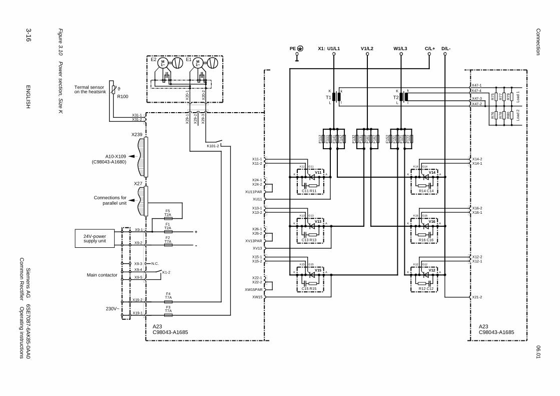
Fig
ure
3.1
0P
ower sectio
n, S
ize K

06.01 Connection
Siemens AG 6SE7087-6AK85-0AA0 ENGLISH 3-17Common Rectifier Operating instructions
V14 V16 V12
V15V13V11
Level B (rear level)
Level A (front level)
Figure 3.11 Arrangement of the thyristor blocks, Size H
V11
V13
V15
V14
V16
V12
Level BLevel A
Figure 3.12 Arrangement of the thyristor blocks, view from right-hand side of unit,Size K

Connection 06.01
3-18 ENGLISH Siemens AG 6SE7087-6AK85-0AA0Common Rectifier Operating instructions
3.7 Parallel connection of parallel unit(s), size K
The output current can be increased by connecting up to 2 "parallel" units of identical rated current in parallelwith the power section of a common rectifier of size K (basic unit).
The following table shows for each basic unit order number, the order number for the corresponding parallel unitthat can be connected in parallel.
Order No. for basic unit Order No. for parallel unit forconnecting in parallel
6SE7041-3EK85-0AA0 6SE7041-3EK85-0AD0
6SE7041-8EK85-0AA0 6SE7041-8EK85-0AD0
6SE7041-3FK85-0AA0 6SE7041-3FK85-0AD0
6SE7041-5FK85-0AA0 6SE7041-5FK85-0AD0
6SE7041-8FK85-0AA0 6SE7041-8FK85-0AD0
6SE7041-3HK85-0AA0 6SE7041-3HK85-0AD0
6SE7041-5HK85-0AA0 6SE7041-5HK85-0AD0
6SE7041-8HK85-0AA0 6SE7041-8HK85-0AD0
Table 3.8 Corresponding basic and parallel units
The parallel units have the same technical data as the corresponding basic units.The parallel units do not include a CUR electronic module and are fitted with a C98043-A1695 (A23) PowerInterface module instead of a C98043-A1685 (A23) Power Interface module.The parallel units do not require a separate external 24V power supply (via X9). The contactor for the parallelunit(s) is controlled via X9 of the basic device. Please observe contact ratings (if not sufficient, use an auxiliaryrelay).
A 50-core ribbon cable is used to transfer firing pulse signals and monitoring signals. It also carries the powersupply for the parallel units.
Parallel connection to a basic unit:The female terminal strip X27 on module A23 of the basic unit is connected to the male terminal strip X28 onmodule A23 of the parallel unit via a 50-core ribbon cable.
Parallel connection of a second parallel unit:The female terminal strip X27 on module A23 of the first parallel unit is connected to the male terminal strip X28on module A23 of the second parallel unit via a 50-core ribbon cable.
The parallel unit(s) should be installed to the left of the basic unit (see Figure 3.13).
X27X27
X28
X27
X28
A23C98043-A1695
A23C98043-A1695
A23C98043-A1685
Secure cable, whose insulation hasbeen stripped over a length of 30mm,by means of a shield clamp.
Parallel unit Parallel unit Basic unitSecure cable, whose insulation hasbeen stripped over a length of 30mm,by means of a shield clamp.
Figure 3.13 Connection of firing pulse signals and monitoring signals for the parallel units

06.01 Connection
Siemens AG 6SE7087-6AK85-0AA0 ENGLISH 3-19Common Rectifier Operating instructions
NOTES
The permissible output current for a parallel arrangement is reduced (due to the current division between thepower sections) by 10% as compared with the sum of the rated currents of the separate power sections.
The following is required to ensure even current distribution between the basic unit and parallel unit(s).
♦ Use of identical power components (see above table for the corresponding parallel units and basic unit)
♦ Identical phases for the power section connections of the common rectifiers between the basic units andparallel unit(s)
♦ Commutating reactors specific for each basic and parallel unit with identical technical data. Each separateparallel path must have a minimum uk value of 2%!
X27
X28
X27
X28
X117
Mains DC link
Basic unit
Parallel unit (1)
Parallel unit 2
♦ Identical fuses for basic unit and parallel unit(s)
♦ Identical cable lengths leading to the power section connections of the basic and parallel units
Output reactors in the DC circuit are not permitted.
WARNING
Fault-free operation can only be guaranteed if the phases at the power sectionterminals (U1/L1, V1/L2, W1/L3, C/L+ and D/L-) between the basic unit andparallel unit(s) are identical.
Non-compliance with this condition may result in destruction of the powersections of the basic and parallel units.
The maximum permissible total cable length between the basic unit and parallel unit 1 or parallel unit 2 (ifpresent) is 15 m.
A 50-way shielded round cable with a length of 4 m is contained in the scope of supply of a parallel unit (spareparts order No.: 6SY7010-8AA00).
Order No. for one cable "10 m round, screened": 6QX5368 (other lengths on request):
On connecting this round, 50-core cable with a diameter of 14 mm, its screen has to be laid bare by cutting awaythe insulation and it must be connected to earth on both devices. With regard to the immunity to interference ofthe system, it is recommended that the cable be installed in a separately earthed shielded cable duct.
The cable length within the unit from the connector on the A23 module (X27 or X28) to the top edge of the uniton the rear panel (cabinet wall) is 1m to the left and 1.8 m to the right. This includes the spare length required forremoving the A23 module with its carrier board for service purposes.

Connection 06.01
3-20 ENGLISH Siemens AG 6SE7087-6AK85-0AA0Common Rectifier Operating instructions
WARNING
When the A23 module of a parallel unit is removed for servicing, the terminals ofthe current transformers are open. The parallel unit must not be operated,otherwise the current transformers of the parallel unit can be damaged bycurrents from the snubber RC network.
Non-compliance may result in the destruction of the current transformer of aparallel unit.
Parameterization:
Parameter P076 (configuration of the power section)
P076 = 01x ....1 common rectifier parallel unit is connected in parallel with the basic unit
P076 = 02x ....2 common rectifier parallel units is connected in parallel with the basic unit
HINWEIS
With the parameterization P076=00x, a connected parallel unit still receives firing pulses and carries current, itis only the monitoring for current asymmetry (over-current or under-current in the parallel power section ascompared to the current in the basic unit, -F034) that is not active.
The results of the thyristor test (selected via P353) are only conditionally applicable when units are connectedin parallel.
Start-up:
The start-up procedure is exactly the same as in the case of a single basic unit. The final cabling (parallelconnection of the power sections and coupling via the 50-core ribbon cable) must however already existbecause the parallel units also carry current during circuit identification.
Note: In the case of 1 or 2 parallel units connected in parallel, the value of parameter P144 (DC linkcapacitance) only represents a half or 1/3 of the actual DC link capacitance because parameter P075 forthe basic unit contains the rated current for a single power section.
LED display on the A23 power interface module (C98043-A1695) of a parallel unit:
Green LED (H11) lit: The power supply on this parallel unit is operating.
Yellow LED (H12) lit: On this parallel unit, the highest temperature of any power section connected in parallelhas been measured (this does not necessarily mean over-temperature). If the yellow H12LED is not lit on any of the parallel units, the highest temperature is currently measured atthe power section of the basic unit.
Red LED (H13) lit: A fuse has fused on this parallel unit.
CAUTION
On parallel connection the rating of the relay contact K1-2 (connection X9-4, X9-5) should be taken intoaccount (refer to Chapter 3.2).

06.01 Connection
Siemens AG 6SE7087-6AK85-0AA0 ENGLISH 3-21Common Rectifier Operating instructions
3.7.1 Single-line diagram with suggested circuit arrangement for parallel connection
X1
: C
/L+
X1
: D
/L-
X2
7
X2
39
X9-
1
X19
-1X
19-2
X9-
2X
9-3
X9-
4X
9-5
X9-
1
X19
-1X
19-2
X9-
2X
9-3
X9-
4X
9-5
A23C98043-A1685
X2
8X
27
X19
-1X
19-2 X
19-1
X19
-2
A23C98043-A1695
X1
: U
1 V
1 W
1
L1
L2
L3
X1
: C
/L+
X1
: D
/L-
PE
X1
: U
1 V
1 W
1
L1
L2
L3
PE
ϑ
K1-
2
K2
123
123
ϑ
K1
K3
+-
Power section, parallel unit
1AC
230
V
Loa
d
1AC
230
V
Filt
er(o
ptio
nal)
to e
lect
roni
cs m
odul
eA
10-
X10
9
Par
alle
l uni
tB
asic
uni
t
Con
nec
tions
for
seco
nd
para
llel u
nit
Filt
er(o
ptio
nal)
Fan
un
it
Ter
mis
tor
Loa
d
Fan
un
it
DC
51
0V -
620
VD
C 6
75V
- 7
80V
DC
89
0V -
930
V
Power section, basic unit
24V
pow
ersu
pply
un
it
3AC
50-
60H
z, 4
00V
3AC
50-
60H
z, 5
00V
3AC
50-
60H
z, 6
90V
1AC
50-
60H
z, 2
30V
Ter
mis
tor
Vo
ltag
em
easu
rem
ent
Fus
em
onito
ring
Fus
em
onito
ring
of th
e m
ain
pow
er
switc
h
Figure 3.14 Single-line diagram with suggested circuit for parallel connection, size K

Connection 06.01
3-22 ENGLISH Siemens AG 6SE7087-6AK85-0AA0Common Rectifier Operating instructions
3.8 12-pulse mode (only possible with the optional RS485 interface)
3.8.1 General information on 12-pulse mode, application
12-pole operation is possible only with equipment software version 3.0 and higher.
12-pulse mode is implemented to reduce the harmonic loading on the mains supply..
Two 6SE70 units (common rectifiers) are connected in parallel on the output side and supplied on the line sidewith two 3-phase AC supplies, galvanically isolated and with a phase offset of 30 degrees. One unit, the "12-pulse master", controls the DC link voltage and provides the setpoint current for the other unit, the "12-pulseslave".
Note: A unit described here as a "slave" is a completely normal common rectifier with a CUR electronic moduleand is only transformed into a "12-pulse slave" by the appropriate parameterization. The term "12-pulse slave"must not be confused with a "parallel unit" for the connection of power sections in parallel because the latterdoes not contain a CUR electronic module and has a different order No. (see Section 3.7).
The two 3-phase galvanically isolated AC supplies with a phase offset of 30 degrees are usually generated usinga transformer with 2 different secondary systems (e.g. Y y6 d5, i.e. primary winding: star, secondary winding 1:star, secondary winding 2: delta). A transformer of this type will be referred to below as a "12-pulse transformer".
To implement 12-pulse mode, the two common rectifiers must be coupled via a fast serial link. The SST2 serialinterface for the basic unit is used for this purpose which is however only available as an RS485 interface oncethe optional A2 submodule (C98043-A1690) has been plugged into the A10 CUR electronic module (C98043-A1680). See Sections 9.6 and 3.8.7).
The transmission protocol used for SST2 is the "Peer-to-Peer" protocol.

06.01 Connection
Siemens AG 6SE7087-6AK85-0AA0 ENGLISH 3-23Common Rectifier Operating instructions
3.8.2 Hardware requirements, configuration of the power sections
The sub-currents of the 3-phase AC supplies are decoupled on the line side (line side with respect to the unitterminals) through inductances (due to the secondary leakage inductance of the 12-pulse transformer,commutating reactors).
Note: A 12-pulse transformer alone is not always sufficient for decoupling because the two secondary windingsof the transformer are magnetically coupled. When the "12-pulse master" and the "12-pulse slave" are directlysupplied from a "high-power" 12-pulse transformer (i.e. without the intermediate connection of commutatingreactors), the DC link currents (in non-pulsating operation) each comprise 30 degree current blocks because atintervals of 30 degrees, a commutating process takes place from secondary winding 1 to secondary winding 2 orvice-versa. Only if you use a 12-pulse transformer with sufficiently large secondary leakage inductances (or lowmagnetic coupling between secondary winding 1 and secondary winding 2) or if you use a " double-tiertransformer", in which no magnetic coupling exists between the two secondary voltage systems, is it possible todispense with additional commuting reactors.
The following points must be complied with:
• Supply of the power sections of the 12-pulse master and the 12-pulse slave from galvanically isolated3-phase AC systems
• Decoupled infeeds - i.e. commuting reactors after the 12-pulse transformer or 12-pulse transformer withsufficiently large secondary leakage inductances (or low magnetic coupling between secondary winding 1 andsecondary winding 2) or use of a "double-tier transformer".
• Identical inductances in the 12-pulse master and 12-pulse slave power section branches.
• Identical voltage levels at the 12-pulse master and 12-pulse slave, otherwise with a control angle of 0degrees, this will cause unequal current division (with a control angle of 0 degrees, closed-loop control is notpossible - the unit with the higher voltage level carries more current).
• With Ud reduction, current asymmetry (as a result of a control angle of 0 degrees and differing voltage levels)can be prevented or considerably reduced.
• An output reactor must not be used in the DC link.
Recommended power section configurations:
Note: It is of no consequence whether the "12-pulse master" or "12-pulse slave" is supplied by the delta windingof the 12-pulse transformer. It is only important that a phase offset of 30 degrees is present between the twogalvanically isolated supplies. In contrast to the following configuration examples, the "12-pulse master" and "12-pulse slave" can also be exchanged with respect to their connection to the "12-pulse transformer".
a) Power section incoming feeder for two power supply units
Refer to the notes in Chapter 3.1 for details of the decoupling (commutating) reactors between the 12-poletransformer outputs and the incoming supply rectifier bridge.
X117
X117
Mains
"12-pulse transformer"
DC link
Reactor
Reactor12-pulse slave
12-pulse master
Figure 3.15 Power section incoming feeder for two power supply units

Connection 06.01
3-24 ENGLISH Siemens AG 6SE7087-6AK85-0AA0Common Rectifier Operating instructions
b) Example of a configuration for 12-pulse mode and parallel connection of units of size K to obtain themaximum output current
With the following power section arrangement 2 equipment groups of type of construction K operate in 12-pole operation, in order to achieve the maximum possible output current. The first equipment groupcomprises a basic unit configured to act as the "12-pole master“, with which 2 parallel units (containing noCUR electronic card, refer to Chapter 3.7) are connected in parallel. The second equipment group comprisesa basic unit configured to act as the "12-pole slave“, with which likewise 2 parallel units are connected inparallel.
X27
X28
X27
X28
X27
X28
X27
X28
X117
X117
Parallel unit
Basic unit(12-pulse master)
Mains
Reactor
"12-pulse transformer"
DC link
Basic unit(12-pulse slave)
Parallel unit
Parallel unit
Parallel unit
Reactor
Reactor
Reactor
Reactor
Reactor
Figure 3.16 Example of a configuration for 12-pulse mode and parallel connection of units of size K to obtain the maximum outputcurrent
3.8.3 Parameterization for 12-pulse mode
In this application, two 6SE70 units (common rectifiers) are coupled via the SST2 serial interface (optionalRS485 interface PTP1) using "Peer-to-Peer" protocol. One unit is parameterized as a 12-pulse master and oneis parameterized as a 12-pulse slave.
Selection of the basic or reserve setting (index i001 or i002) of the appropriate "Source selection parameter“(P554, P555, ...) is described in Section 4.1.2.

06.01 Connection
Siemens AG 6SE7087-6AK85-0AA0 ENGLISH 3-25Common Rectifier Operating instructions
"12-pulse master"-6SE70 unit "12 pulse slave"-6SE70 unit
Function: Controls the DC link voltage and providesthe setpoint current for the 12-pulse slave unit via theSST2 interface and control commands (and receivescontrol commands).
Function: In current control mode, receives thesetpoint current and control commands via the SST2interface from the 12-pulse master (and sendscontrol commands).
P051= 3 (Access level: Expert mode) P051= 3 (Access level: Expert mode)
SST2 interface definition:
P688= 1 (protocol selection "Peer-to-Peer")
P684.i003= 13 (baudrate 187500 Bd)(factory setting)
P686.i003= 2 (2 process data words)(factory setting)
P687.i003= 1 ms (telegram failure time)(factory setting) (see Section 3.8.6)
SST2 interface definition:
P688= 1 (protocol selection "Peer-to-Peer")
P684.i003= 13 (baudrate 187500 Bd)(factory setting)
P686.i003= 2 (2 process data words)(factory setting)
P687.i003= 1 ms (telegram failure time)(factory setting) (see Section 3.8.6)
SST2 send channel:
P681.i001= 599 (1st process data item iscontrol/status word for 12-pulse mode)(factory setting)
P681.i002= 34 (2nd process data item is the setpointcurrent)(factory setting)
SST2 send channel:
P681.i001= 599 (1st process data item iscontrol/status word for 12-pulse mode)(factory setting)
Use of SST2 receive data:
P573.i001 (or i002) = 6001 (1st receive data issource for "No external fault 3")(but should only be parameterized when the 12-pulsemaster is required to go into the "fault" state in theevent of a 12-pulse slave fault - see Section 3.8.6)
Use of SST2 receive data:
P554.i001 (or i002) = 6001 (ON/OFF1)
P555.i001 (or i002) = 6001 (not OFF2)(with the "fault" state for the 12-pulse master or when"no 12-pulse mode" is selected on the 12-pulsemaster (see P583.i001 or i002), OFF2 is signaled)
P561.i001 (or i002) = 6001 (Run enable)(the 12-pulse slave only receives the run enablewhen the 12-pulse master is in the "run" state)
P566.i001 (or i002) = 6001 (RESET)(Source 2 for reset... this facilitates an external resetfrom the master)
P486.i001 (or i002) = 6002 (2nd receive data item isthe setpoint current)
Definition of the unit as a 12-pulse unit:
P583.i001 (or i002) = 1 (12-pulse mode is selected)
Definition of the unit as a 12-pulse unit:
P583.i001 (or i002) = 1 (12-pulse mode is selected)
Definition of the unit as a master or slave:
P587.i001 (or i002) = 0 (master)(factory setting)
Definition of the unit as a master or slave:
P587.i001 (or i002) = 1 (slave)
Special functions:
P354 = 0 (Earth short-circuit test deactivated whenthe unit is supplied by a non-earthed supply - e.g.from the delta winding of the 12-pulse transformer)
Special functions:
P354 = 0 (Earth short-circuit test deactivated whenthe unit is supplied by a non-earthed supply - e.g.from the delta winding of the 12-pulse transformer)
Table 9 Parameterization for 12-pulse mode

Connection 06.01
3-26 ENGLISH Siemens AG 6SE7087-6AK85-0AA0Common Rectifier Operating instructions
3.8.4 Control/status word for 12-pulse mode (r599) and control word 2, bit 23
The following table shows how the bits of the control/status word for 12-pulse mode (r599) are formed from thebits of control words 1 and 2 (r550, r551), the bits of status word 1 (r552), the bits of the first SST2 receive data(r599 sent from the Peer-to-Peer partner) and the internal unit status with Boolean arithmetic or how these bitsare connected together (negation is represented with a slash):
Control/status word for 12-pulse mode (r599)
Bit Logical linking (or meaning in the high state)
r599.0 r550.0 (ON or not OFF1) AND /r552.3 (no fault) AND r551.23 (12-pulse mode is selected)
r599.1 r550.1 (run condition or not OFF2) AND /r552.3 (no fault) AND r551.23 (12-pulse mode is selected)
r599.2 r550.2
r599.3 r552.2 (Message for RUN state)
r599.4 (for internal diagnostic purposes: 1, as long as trigger delay is running, as of Software Version 4.3)
r599.5 Message: Unit is a Rectifier/Regenarating Unit (high state: Unit is a comon rectifier)
(P070 ≤ 100) (P070 ≥ 101)
r599.6 Message: DC link forming or current identification is being carried out
r599.7 r550.7 (fault reset)
r599.8 r550.8 (typing 1 ON) AND /r552.3 (no fault) AND r551.23 (12-pulse mode is selected)
r599.9 r550.9 (typing 2 ON) AND /r552.3 (no fault) AND r551.23 (12-pulse mode is selected)
r599.10 r550.10 (PLC control)
r599.11 r550.11 (Ud-reduction requested)
r599.12 r552.10 (Message: "Regenerating ready") orHigh when with 12-pulse mode selected (r551.23= 1), the unit is held in state r000 = "--" (because"circuit identification" or "forming" is taking place on the partner unit, or because the unit is waitingfor the "run" state of the 12-pulse slave unit (while the slave unit is carrying out the earth short-circuit test and the maximum waiting time of 5 s in state r000 = "--" has not yet elapsed))
Dieses Bit ist bei einer Einspeiseeinheit nicht von Bedeutung !
r599.13 r552.3 (Message: NO fault)
r599.14 r552.14 (Message: "Motoring" (Rectifier bridge is carrying current or is ready to carry current orneither rectifier nor regenerating bridge are carrying current))
Dieses Bit ist bei einer Einspeiseeinheit nicht von Bedeutung !
r599.15 r550.15 (No external fault 1)
Table 10 Control/status word for 12-pulse mode (r599)
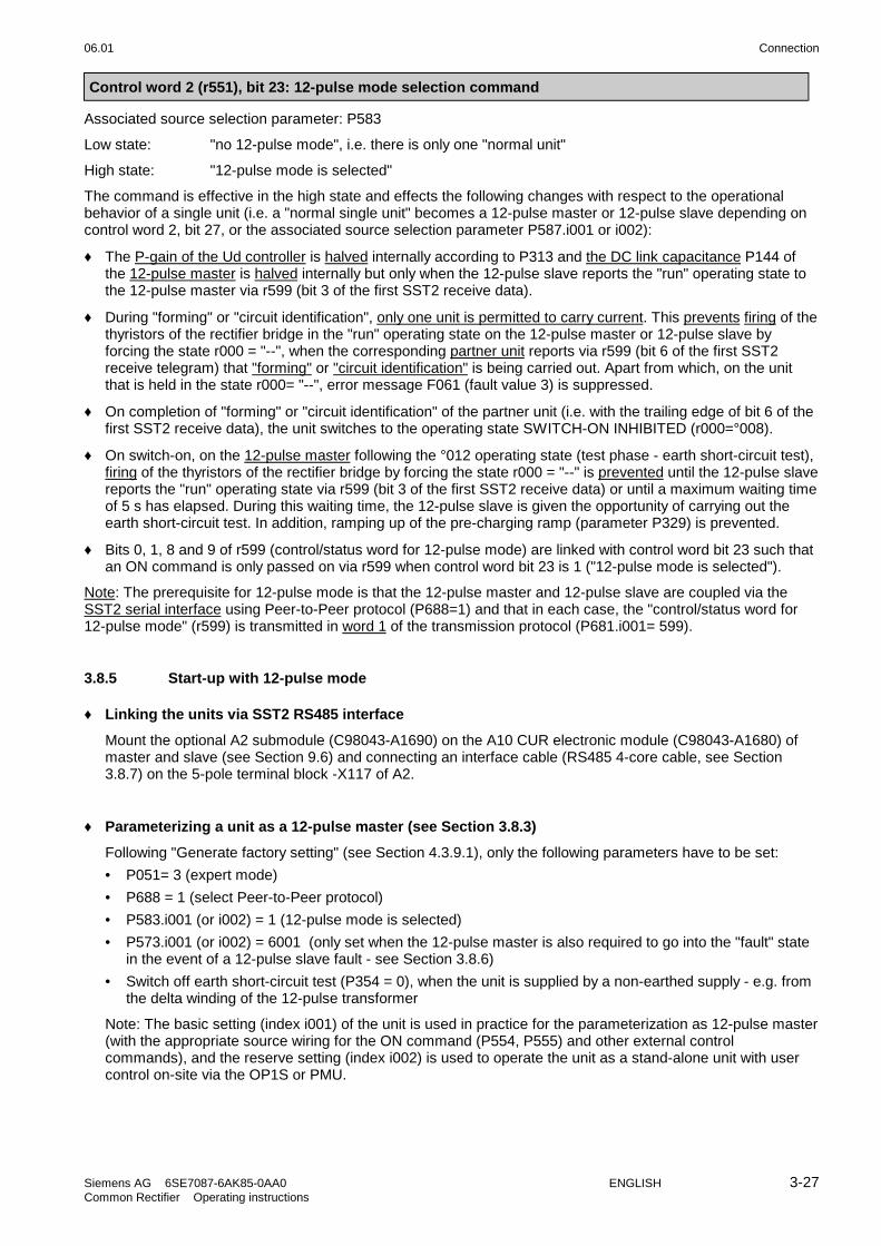
06.01 Connection
Siemens AG 6SE7087-6AK85-0AA0 ENGLISH 3-27Common Rectifier Operating instructions
Control word 2 (r551), bit 23: 12-pulse mode selection command
Associated source selection parameter: P583
Low state: "no 12-pulse mode", i.e. there is only one "normal unit"
High state: "12-pulse mode is selected"
The command is effective in the high state and effects the following changes with respect to the operationalbehavior of a single unit (i.e. a "normal single unit" becomes a 12-pulse master or 12-pulse slave depending oncontrol word 2, bit 27, or the associated source selection parameter P587.i001 or i002):
♦ The P-gain of the Ud controller is halved internally according to P313 and the DC link capacitance P144 ofthe 12-pulse master is halved internally but only when the 12-pulse slave reports the "run" operating state tothe 12-pulse master via r599 (bit 3 of the first SST2 receive data).
♦ During "forming" or "circuit identification", only one unit is permitted to carry current. This prevents firing of thethyristors of the rectifier bridge in the "run" operating state on the 12-pulse master or 12-pulse slave byforcing the state r000 = "--", when the corresponding partner unit reports via r599 (bit 6 of the first SST2receive telegram) that "forming" or "circuit identification" is being carried out. Apart from which, on the unitthat is held in the state r000= "--", error message F061 (fault value 3) is suppressed.
♦ On completion of "forming" or "circuit identification" of the partner unit (i.e. with the trailing edge of bit 6 of thefirst SST2 receive data), the unit switches to the operating state SWITCH-ON INHIBITED (r000=°008).
♦ On switch-on, on the 12-pulse master following the °012 operating state (test phase - earth short-circuit test),firing of the thyristors of the rectifier bridge by forcing the state r000 = "--" is prevented until the 12-pulse slavereports the "run" operating state via r599 (bit 3 of the first SST2 receive data) or until a maximum waiting timeof 5 s has elapsed. During this waiting time, the 12-pulse slave is given the opportunity of carrying out theearth short-circuit test. In addition, ramping up of the pre-charging ramp (parameter P329) is prevented.
♦ Bits 0, 1, 8 and 9 of r599 (control/status word for 12-pulse mode) are linked with control word bit 23 such thatan ON command is only passed on via r599 when control word bit 23 is 1 ("12-pulse mode is selected").
Note: The prerequisite for 12-pulse mode is that the 12-pulse master and 12-pulse slave are coupled via theSST2 serial interface using Peer-to-Peer protocol (P688=1) and that in each case, the "control/status word for12-pulse mode" (r599) is transmitted in word 1 of the transmission protocol (P681.i001= 599).
3.8.5 Start-up with 12-pulse mode
♦ Linking the units via SST2 RS485 interface
Mount the optional A2 submodule (C98043-A1690) on the A10 CUR electronic module (C98043-A1680) ofmaster and slave (see Section 9.6) and connecting an interface cable (RS485 4-core cable, see Section3.8.7) on the 5-pole terminal block -X117 of A2.
♦ Parameterizing a unit as a 12-pulse master (see Section 3.8.3)
Following "Generate factory setting" (see Section 4.3.9.1), only the following parameters have to be set:
• P051= 3 (expert mode)
• P688 = 1 (select Peer-to-Peer protocol)
• P583.i001 (or i002) = 1 (12-pulse mode is selected)
• P573.i001 (or i002) = 6001 (only set when the 12-pulse master is also required to go into the "fault" statein the event of a 12-pulse slave fault - see Section 3.8.6)
• Switch off earth short-circuit test (P354 = 0), when the unit is supplied by a non-earthed supply - e.g. fromthe delta winding of the 12-pulse transformer
Note: The basic setting (index i001) of the unit is used in practice for the parameterization as 12-pulse master(with the appropriate source wiring for the ON command (P554, P555) and other external controlcommands), and the reserve setting (index i002) is used to operate the unit as a stand-alone unit with usercontrol on-site via the OP1S or PMU.

Connection 06.01
3-28 ENGLISH Siemens AG 6SE7087-6AK85-0AA0Common Rectifier Operating instructions
♦ Parameterizing a unit as a 12-pulse slave (see Section 3.8.3)
Using P077 = 5 or 6, almost all settings required for the parameterization as a 12-pulse slave can be carriedout automatically (see Chapter 4.3.9.1). Meaning of P077 = 5 or 6:
P077= 5: Basic setting (index i001): 12-pulse slave (all control is carried out via the master)Reserve setting (index i002): stand-alone unit with operator control via PMU
P077= 6: Basic setting (index i001): 12-pulse slave (all control is carried out via the master)Reserve setting (index i002): stand-alone unit with operator control via OP1S
Note: When the reserve setting is selected, the unit operates as a stand-alone unit with on-site operatorcontrol. Changeover between the basic and reserve settings takes place via binary input 5 (P590=1005), butthe reserve setting can be set permanently via P590= 1.
Procedure for carrying out the P077-dependent factory setting (see Section 4.3.9.1):
• Set P051= 3 (expert mode)
• Set P052= 2 (Select "Initialize" function (set MLFB), so that P077 can be modified)
• Set P077= 5 or 6 (Select the required P077-dependent parameter setting)
• Set P052= 0 and press the <P> key (terminate the "initialize" function)
• Set P052= 1 (select the function "Generate manufacturer setting"; when the <P> key is pressed, allparameters are reset to their factory setting or to the P077-dependent value)
If only those parameter values that are dependent on P077 are required to be changed and all otherparameters should remain unchanged, the following procedure is necessary:
• Set P051= 3 (expert mode)
• Set P052= 2 (select "Initialize" function (set MLFB))
• Note P070 and set P070= 0
• Set P077= 5 or 6 (select the required P077-dependent parameter setting)
• Set P052= 0 and press the <P> key (read in the parameter values dependent on P077)
• Move the F060 error message into the "background" by pressing <P>+<H>
• Set P052= 2 (select "Initialize" function (set MLFB) again)
• P070= noted value (restore MLFB)
• P052= 0 and press the <P> key (MLFB is read in and the dependent parameters P071, P075 and P076are set)
• Move the F060 error message into the "foreground" again by pressing <P>+<T>, and reset by pressingthe <P> key
Additional parameter settings for the 12-pulse slave:
• P051= 3 (expert mode)
• P688 = 1 (Peer-to-Peer protocol)
• Switch off earth short-circuit test (P354 = 0), when the unit is supplied from an unearthed supply, e.g. fromthe delta winding of the 12-pulse transformer
• For factory settings in accordance with P077= 5 or 6, binary input 1 is a source for "No external fault 1"and binary input 2 is a source for "No external warning 1". If this is not required, e.g. in the case of openterminals, P575 = 1 and P588 = 1 must be set.

06.01 Connection
Siemens AG 6SE7087-6AK85-0AA0 ENGLISH 3-29Common Rectifier Operating instructions
♦ Circuit identification:
Circuit identification should be carried out successively on the 12-pulse master and on the 12-pulse slave.P052= 21 must be set on each unit for this purpose, and the switch-on command for the 12-pulse slavecomes from the 12-pulse master (the control word wiring ensures that the partner unit, in each case, does notcarry current or is held in the operating state r000= "--".
• Circuit identification procedure for 12-pulse master:
Set P052= 21 on the 12-pulse master unit, switch on ⇒ circuit identification is carried out on the 12-pulsemaster
• Circuit identification procedure for 12-pulse slave:
Set P052= 21 on the 12-pulse slave unit, switch on the 12-pulse master unit ⇒ circuit identification iscarried out on the 12-pulse slave.
Note: If circuit identification is carried out with the basic settings selected (operation as a 12-pulse slave,all control is from the 12-pulse master), the switch-on command must come from the 12-pulse master andthe power terminals of the 12-pulse master unit must be connected to the supply voltage.
Note: When the reserve setting is selected on the 12-pulse slave unit (with appropriate parameterizationof index i002 of the "Source selection parameters" P554, P555, ...) it is also possible to issue the switch-on command for circuit identification on the slave unit on-site via the PMU or OP1S.
♦ Setting additional functions:
If required, activate the "auto restart" (via P366= 2) on the master and on the slave unit. This will be effectivein the event of failure of the electronics supply voltage provided that the Peer-to-Peer telegram failuremonitoring time has been switched off via P687.i003= 0.
3.8.6 Redundancy mode
If both common rectifiers are rated such that each separate unit is capable of carrying the full load current,the following possibilities are available with respect to redundant operation:
• Uninterrupted changeover of the 12-pulse master unit to stand-alone 6-pulse mode in the event offailure of the 12-pulse slave unit during 12-pulse mode:
If the 12-pulse master is required to continue to run in "normal" stand-alone 6-pulse mode in the event offailure of the 12-pulse slave unit without interruption, "External fault 3" must not be "wired" to the Peer-to-Peerinterface, but instead the parameterization P573.i001 (or i002) = 1 is required on the 12-pulse master. If themaster unit is also required to continue to run without an interruption in the event of failure of the Peer-to-Peer interface cable, the Peer-to-Peer telegram failure monitoring time also has to be switched off viaP687.i003= 0 on the master.
• Reconnection of the 12-pulse slave unit during operation of the master:
If (12-pulse) operation of a 12-pulse slave unit is required to be reinstated following an interruption of thePeer-to-Peer interface cable without error message and during (stand-alone 6-pulse) operation of the masterunit, the Peer-to-Peer telegram failure monitoring time also has to be switched off via P687.i003= 0 on the12-pulse slave unit.
• Changeover of the 12-pulse slave unit to stand-alone 6-pulse mode in the event of failure of the 12-pulse master unit:
Bei Ausfall des Master-Gerätes während des 12-Puls-Betriebes ist ein fast unterbrechungsfreies UmschaltenIn the event of failure of the master unit during 12-pulse mode, it is possible for the 12-pulse slave unit tochange over to stand-alone 6-pulse mode almost without interruption, because all external control commandsthat are wired to the terminals of the master unit (e.g. ON command) are also carried to the terminals of the12-pulse slave unit. Externally implemented logic must ensure that in the event of failure of the master unit,the 12-pulse slave is switched from the basic to the reserve setting. The 12-pulse slave must beparameterized appropriately in the reserve setting to facilitate stand-alone 6-pulse mode with external control.The Peer-to-Peer telegram failure monitoring time also has to be switched off via P687.i003= 0 in this case.

Connection 06.01
3-30 ENGLISH Siemens AG 6SE7087-6AK85-0AA0Common Rectifier Operating instructions
Note:With the parameterization P687.i003 = 0 AND P681.i001 = 599, in the event of telegram failure, bits 3 and 6of the first SST2 Peer-to-Peer receive data (i.e. the control/status word for 12-pulse mode sent from thepartner unit) are set to 0.
3.8.7 RS485 interface cable for the Peer-to-Peer link on SST2
The RS485 interface cable required for the serial Peer-to-Peer link on SST2 is in the form of a four-wireconnection.
A screened 4-core cable must be connected at the screw terminals of the 5-pole plug of terminal block -X117 onsubmodule A2 (C98043-A1690). Submodule A2 is fitted to the CUR A10 electronics module (see Section 9.6).The 4-core cable is not included in the scope of delivery.
X117
1
2
3
4
5
A2
X117
1
2
3
4
5
A2
MM
12-pulse master 12-pulse slave
Figure 3.17 Connecting cable for "Peer-to-Peer" communication on SST2 (between the terminals of the A2 submodule (C98043-A1690))

06.01 Start-Up
Siemens AG 6SE7087-6AK85-0AA0 ENGLISH 4-1Common Rectifier Operating Instructions
4 Start-Up
4.1 Introduction and handling start-up
WARNING
Despite disconnecting the power terminals from the supply, voltage may still bepresent on terminal X19 due to the external fan supply.
4.1.1 Handling the start-up instructions
NOTE
♦ Section 4.2 First start-up:First start-up of the common rectifier
♦ Section 4.3 Start-up aids:Index-type reference for start-up and use of the common rectifier, which only has to be used if actuallyrequired!
♦ Section 4.4 Function diagrams:Graphical overview of the setpoint channel, open-loop/closed-loop control, analog inputs/outputs, and thecommon rectifier data sets
4.1.2 General explanation of the terminology and functional scope of the common rectifier
NOTE
The software used for the power supply unit is identical to that used for the power supply units andregenerative power supply units of equipment series 6SE70.
The functional difference between power supply units and combined power supply and regenerative units isdefined by means of the parameter P070.
Any remarks concerning "regeneration" in these operating instructions (e.g. concerning control word 1) shouldbe ignored.
Abbreviations:
♦ Abbreviations used: Refer to Section 15 "Information, notes"
Mode and automatic control variants of the common rectifier:
♦ "Function block diagrams: Open and closed-loop control": see Section 4.4
♦ Application: Power supply of the variable-voltage DC link of SIMOVERT converters of the6SE70 series

Start-Up 06.01
4-2 ENGLISH Siemens AG 6SE7087-6AK85-0AA0Common Rectifier Operating Instructions
♦ Closed-loop control variant:
a) Parallel connection (see Section 3.7)The output current can be increased by connecting up to 2 "parallel units of identical ratedcurrent in parallel with the power section of a common rectifier of size K ("basic unit"). The"basic unit" controls the DC-link voltage. The firing pulses of the basis unit are transmitted tothe parallel unit(s) via ribbon cable. A parallel unit does not contain a CUR electronic module.When connected in parallel, the load current must be reduced by 10 % with respect to thetotal rated current.Due to the use of identical power sections, commutating reactors as well as identical cablelengths for connection to the mains supply, an almost symmetrical division of currentbetween the "basic unit" and the "parallel unit(s)" can be ensured.
b) 12-pulse mode (see Section 3.8)Two common rectifiers are connected in parallel on the output side and fed on the line sidewith galvanically isolated AC supplies, each displaced by 30 degrees. A common rectifiercontrols the DC-link voltage and supplies a second common rectifier with the currentsetpoint. The second common rectifier that is linked to the first via the SST2 serial interface(RS485 interface option) with peer-to-peer protocol only becomes a "12-pulse slave" afterparameterization.12-pulse mode is used to reduce the harmonic loading on the system and to increase theperformance for high-power common rectifiers.
"Process data":
♦ "Process data" are commands and setpoints from "outside" fed into the common rectifier, aswell as signals and actual values which are output from the common rectifier
SetpointchanalOp./cl-loopcontrol
Commands"Control Word"
Setpoints
Messages"status word"
Actual values
Common Rectifier
Process data
e.g.: "ON command"
Only: Id setpoint in12-pulse operation
e.g.: "fault
e.g. output current
- Binary inputs BE (terminals)- Parameterizing unit (PMU) - Operator control panel (OP)- Serial interfaces (SST1, SST2, SCB, CB, TB)
Sources Destinations
- Serial interfaces (SST1, SST2, SCB, CB, TB)
- Binary outputs BA (terminals)- Parameterizing unit (PMU) - Operator control panel (OP)- Serial interfaces (SST1, SST2, SCB, CB, TB)
- Analog outputs AA (terminals)- Parameterizing unit (PMU) - Operator control panel (OP)- Serial interfaces (SST1, SST2, SCB, CB, TB)

06.01 Start-Up
Siemens AG 6SE7087-6AK85-0AA0 ENGLISH 4-3Common Rectifier Operating Instructions
"Indexed" parameters:
♦ Several parameter values are assigned to one parameter number, which can be accessed viathe separate indices (in brief: i001, i002, etc.).The meaning of the indices of the respective parameter (parameter number) is explained in theparameter list in Chapter 5.
P683 i001 = 0
i002 = 2
Bus address for serial interface SST1 (CUR)
Bus address for serial interface on the SCB module
Index 1
Index 2
Example:
"Data sets":
♦ "Indexed" parameters can be sub-divided according to data sets.A data set comprises a group of several parameter values with the same index. Depending onthe status of certain control word bits, a specific data record is accessed(see the function diagram for "selecting the data sets " in Section 4.4).There are two types of data set:
♦ Data sets for basic/reserve setting (B/R) can be selected via control word 2/bit 30Associated source selection parameter: P590Affected parameters: P486, P554 to P557, P561, P565 to P569, P571 to P575,P578, P579, P583 and P586 to P589e.g. for changing over between manual and automatic operation
♦ 4 changeover reserve data sets (RDS) 1, 2, 3 or 4, selectable via the bit combinationin control word 2/bits 18 and 19.Associated source selection parameters: P578, P579Affected parameters: P140 to P144, P160, P161, P310 to P320, P329, P408,P517, P518, P773 to P777Used, e.g. for alternating operation of different inverter types on one commonrectifier

Start-Up 06.01
4-4 ENGLISH Siemens AG 6SE7087-6AK85-0AA0Common Rectifier Operating Instructions
4.2 Initial start-up
4.2.1 Preparatory measures
- Transporting, unpacking, assembling: refer to Section 2- Connecting-up: Refer to Section 3- Read "Introduction and handling the start-up instructions": Section 4.1- Forming: If the inverter(s) connected have been switched off continuously or not connected for more than a
year, is/their link capacitors must be formed (see Section 4.3.9.6).- Connect-up the supply and electronics power supply of the converter with the front panel closed.
The common rectifier is supplied with the "factory setting" (refer to Section 5 "Parameter list", column 4)and access stage 2 (standard mode). That means:
- The settings of the common rectifier data correspond to the unit type according to the MLFB(i.e. converter already initialized).
When supplied, the converter is controlled and parameterized by the parameterizing unit (PMU) located on thefront side of the converter.
P
Switch-onSwitch-off
Displays:
Statusesfaults, alarms,parameter numbers,index numbers,parameter values
Fault acknowledgement andchangeover between:
Parameter numberParameter indexParameter value
ParametersIndicesParameter values
Raise/lowerto select:
A detailed description of the displays as well as the parameterizing and operator control possibilities of thecommon rectifier via the PMU, is provided in Section 6 "operator control".
Parameterization is realized according to Sections 4.2.2 and 4.2.3
NOTE
It is possible to jump into the appropriate sequence step (in the following flow diagrams) if incorrect entrieshave been made, taking into account the access stage (P051) and a function selection (P052) which may berequired.It is recommended that the following parameters and function steps after the jump-in position are re-checkedand executed due to the background calculations !
NOTE
To avoid oscillating of the link voltage in regenerative mode, it is advisable to set parameter P302 of theSIMOVERT Master Drives FC, VC, SC (time constant for filtering the link voltage) to the value 3.

06.01 Start-Up
Siemens AG 6SE7087-6AK85-0AA0 ENGLISH 4-5Common Rectifier Operating Instructions
4.2.2 Parameterization "Standard application"
P050 =
P051 = 2
P053 =
P554 = 2001
P555 = 2001
P052 = 5
P071 =
P408 =
r000 ≤ o009
Commandsvia OP1S?
yes
no
Wait toUd<50V
P052 = 20
P key
Switch-on
Forming
Idle timeof converter
>1year
yes
no
Language (only important when an OP1S is in use; see Section 9.4):0: German, 1: English, 2: Spanish, 3: French, 4: Italian
Access stage "Standard mode“
Parameterization enable
e.g. with P053=6, the parameters from the parameterization unit (PMU) andfrom serial interface 1 of the basic unit (SST1- and therefore also from theoptional user-friendly operator panel OP1S) can be modified.
Operator control
In order to avoid having to wait until the link circuit voltage drops below 20%before switching off, set the parameter P554 = P555.If the unit is to be switched on and off via the optional user-friendly operatorpanel OP1S:P554=2001 Source for control command "ON/OFF1"P555=2001 Source for control command "OFF2"
Drive setting
Supply voltage [V]
Value of the rated voltage at the input bridge
Forming the DC link (if necessary, see Section 4.3.9.6)- The common rectifier must be in status o009 less
(give SWITCH ON command)- Set P408 (forming time: 1.0 to 600.0 minute)- Select function (P052 = 20)- Press P key on the PMU- Press the I key on the PMU- The DC link is formed- When forming is completed, the operating status display appears
(see r006)

Start-Up 06.01
4-6 ENGLISH Siemens AG 6SE7087-6AK85-0AA0Common Rectifier Operating Instructions
P52 = 0
P052 = 22
r000 ≤ o009
r000 ≤ o009
r949.i009 = ?
Logbook
Fault message
Identification Acknowledge
yes
no
Eliminatecause of fault
Ready
P052 = 21
P key
Switch-on
Circuit identification(see Section 4.3.9.7)
- The common rectifier must be in operating state o009 or less(give SWITCH OFF command!)
- Select circuit identification (P052 = 21)- Press the P key on the PMU- Switch on: Press the I key on the PMU- Circuit identification takes place (takes about 10 s)- Following circuit identification, the operating display is activated.- If an error occurs during circuit identification, the identification
process must be repeated (error value r949 assigned to errormemory r947 can provide more information on the cause of error(if the error in index i009 has been reset) see Sections 5.16 and7.1)
Documenting the settings
- Select the "Display modified parameters“ function (P052 = 22).(see Section 4.3.9.8 "Display modified parameters“)Note: Function can only be used with operator control via thePMU
- Enter the values of the modified (i.e. system-specific) parametersin the logbook (Chapter 12)
- Select the "Return" function (P052 = 0)
DC link voltage smoothing
- By parameterizing P302=3 (time constant for smoothing the DClink voltage) on the connected SIMOVERT Master Drive FC thedynamic behavior of the closed-loop control of the DC linkvoltage can be improved.

06.01 Start-Up
Siemens AG 6SE7087-6AK85-0AA0 ENGLISH 4-7Common Rectifier Operating Instructions
4.2.3 Parameterization for "Expert application"
Parameterization can be simplified by selecting an appropriate factory setting via parameter P077 using specialfunctions such as 12-pulse mode with two commom rectifiers coupled via a peer-to-peer link. In this case, this iscarried out by selecting the function "Generate factory setting" as described in Section 4.3.9.1 with P077≠0.Then the parameterization shown in the following diagram can be carried out.In all other cases, the following parameterization is started immediately.
P050 =
P051 = 3
P053 =
P554 = 2001
P555 = 2001
P052 = 5
P071 =
P408 =
r000 ≤ o009
P076 =
P160 =
Commandsvia OP1S?
yes
no
Wait toUd<50V
P052 = 20
P key
Switch-on
Forming
Idle timeof converter
>1year
yes
no
Language (only important when an OP1S is in use; see Section 9.4):0: German, 1: English, 2: Spanish, 3: French, 4: Italian
Access stage "Expert mode“
Parameterization enable
e.g. with P053=6, the parameters from the parameterization unit (PMU)and from serial interface 1 of the basic unit (SST1- and therefore also fromthe optional user-friendly operator panel OP1S) can be modified
Operator control
In order to avoid having to wait until the link circuit voltage drops below20% before switching off, set the parameter P554 = P555.If the unit is to be switched on and off via the optional user-friendly operatorpanel OP1S:P554=2001 Source for control command "ON/OFF1"P555=2001 Source for control command "OFF2"
Drive setting
Supply voltage [V]
Value of the rated voltage at the rectifier bridge
Value of the rated voltage at the rectifier bridge
P076 = 00x No power section connected in parallel01x 1 common rectifier parallel unit connected in parallel with
the basic unit02x 2 common rectifier parallel units connected in parallel with
the basic unit(also see Section 3.7 and Section 5, P076)
Current limits:
P160 = Max. supply current (in % P075 rated current of commonrectifier (factory setting: +150% only briefly available)
Forming the DC link (if necessary; see Section 4.3.9.6)- The common rectifier must be in status o009 or less
(give SWITCH OFF command!).- Set P408 (forming time: 1.0 to 600.0 minutes).- Select function (P052 = 20)- Press the P key on the PMU- Switch on: Press the I key on the PMU- Forming of the DC link takes place- Following the forming process, the status display is activated.
(see r006)

Start-Up 06.01
4-8 ENGLISH Siemens AG 6SE7087-6AK85-0AA0Common Rectifier Operating Instructions
P52 = 0
P052 = 22
r000 ≤ o009
r000 ≤ o009
r949.i009 = ?
Logbook
Ready
Changeprocess dataconnection?
yes
no Connectprocess data
Functionsrequired?software
yes
no Parametrizefunctions
P052 = 21
P key
Switch-on
Fault message
Identification Acknowledge
yes
no
Eliminatecause of fault
Circuit identification(see Section 4.3.9.7)
- The common rectifier must be in operating state o009 or less(give SWITCH OFF command!).
- Select circuit identification (P052 = 21).- Press the P key on the PMU- Switch on: Press the I key on the PMU- Circuit identification takes place (takes about 10 s)- Following circuit identification, the operating display is activated.- If an error occurs during circuit identification, the identification
process must be repeated (error value r949 assigned to errormemory r947 can provide more information on the cause of error(if the error in index i009 has been reset) see Sections 5.16 and7.1)
Change factory setting for: Command and setpoint sources,Destinations for signals and actualvalues
Process data: refer to Section 4.3.1- Control word (commands) / status word (messages)- Setpoint/actual values
Possible process data sources/destinations:(refer to Sections 4.3.2 to 4.3.6)- Binary inputs, binary outputs- Analog inputs- Serial interface in the basic unit (SST1, SST2)
(SST2 only for optional RS485 interface PTP1)- Option boards (SCB, CB, TB)
Simple applications: refer to Section 4.2.5
Possible functions:WEA (automatic restart)
Parameterize functions:Refer to Section 4.3.10 "Functions" and Section 5 "Parameter list"
Documenting the settings
- Select the "Display modified parameters“ function (P052 = 22)(see Section 4.3.9.8 "Display modified parameters“)Note: Function can only be used with operator control via thePMU
- Enter the values of the modified (i.e. system-specific) parametersin the logbook (Chapter 12)
- Select the "Return" function (P052 = 0)
DC link voltage smoothing
- By parameterizing P302=3 (time constant for smoothing the DClink voltage) on the connected SIMOVERT Master Drive FC thedynamic behavior of the closed-loop control of the DC linkvoltage can be improved.

06.01 Start-Up
Siemens AG 6SE7087-6AK85-0AA0 ENGLISH 4-9Common Rectifier Operating Instructions
4.2.5 Simple application examples for connecting process data with connection assignment
Connecting-up: Refer to Section 3.3 "Control terminal strip"
Factory setting:Switch-on/off via the PMU, messages and actual values via the terminal strip.Terminal strip only operational if binary input 5 (BE5) is energized (high signal level corresponds to "reserve").
CUR PMU
P554.1 = 1010ON/OFF1Floating contactFault
ON/OFF1OFF2 (pulse inhibit)Acknowledge
Basic/reserve (activates above commands)
Actual Ud value
P603.1 = 1002
P554.2 = 1001P555.2 = 1002P565.2 = 1003
P590 = 1005
P655.1 = 37
-X104/19 BA2-X104/20 BA2
-X101/6 P24-X101/9 BE1-X101/10 BE2-X101/11 BE3-X101/12 BE4-X101/13 BE5
-X102/15 AAM-X102/14 AA
Manual/automatic operation:
Automatic operation (BE5 high signal level): Command input from the automation unit via serial interface(SST1), the monitoring of external faults via a terminal strip alsopossible.
Manual operation (BE5 low signal level): Command input via the terminal strip.
CUR SST1
P554.2 = 2001P565.2 = 2001
SST
ON/OFF1Acknowledge
Actual Ud value
Floating contactOperation
ON/OFF1
AcknowledgeFault external 1Basic/reserve
Automation unit
P602.1 = 1002
P554.1 = 1001
P565.1 = 1003P575.1 = 1004 P575.2 = 1004 (always activ)P590 = 1005
P655 = 37
-X104/19 BA2-X104/20 BA2
-X101/6 P24-X101/9 BE1-X101/10 BE2-X101/11 BE3-X101/12 BE4-X101/13 BE5
-X102/15 AAM-X102/14 AA

Start-Up 06.01
4-10 ENGLISH Siemens AG 6SE7087-6AK85-0AA0Common Rectifier Operating Instructions
4.3 Start-up aids
4.3.1 Process data
Process data are commands and setpoints which are entered into the common rectifier from "outside" as well assignals and actual values which the common rectifier outputs.
4.3.1.1 Control word (control word 1 and control word 2)
Control/status word for 12-pulse mode, see Section 3.8
4.3.1.1.1 Introduction and application example
The two control words 1 (bits 0 to 15) and 2 (bits 16 to 31) output commands and external signals (messages) tothe common rectifier.Their status can be read-out via parameter r550 or r967 (control 1) and r551 (control word 2).An overview is provided in Section 4.3.1.1.2 "Overview of the control word".The significance of the possible commands and signals, entered externally, is described in Section 4.3.1.1.7"Significance of the control word commands".Every control word bit is assigned a selection parameter, which defines from which source(s) this bit can bechanged (refer to Section 4.3.1.1.2, right-hand column).The selection parameters for the sources are, with the exception of P590 (source selection for control word bit30 "basic/reserve setting") and P591 (source selection for control word bit 31 "Main contactor checkback signal")are indexed 2x as follows:
Index i001 Basic settingi002 Reserve setting
An overview of possible sources, which are assigned fixed values (0-6005, non-consecutively), are provided inSection 4.3.1.1.3 to 4.3.1.1.6 "Selecting the source for the control word".In this overview, values 0 and 1 are an exception; sources are not selected with these values, but the bits are setpermanently to 0 (LOW) or 1 (HIGH) (also refer to select parameters P554 to P591 in Section 5 "parameter list").
NOTE
The control word commands "OFF2" (bit1) and "Acknowledge" (bit7) are always simultaneously effective from3 sources (can be parameterized) !"Acknowledge" (bit7) is also always effective from the PMU !
NOTICE
If the "On" command (bit 0) is connected to a serial interface (SST1, CB/TB, SCB-SST), then the followingmust be observed for safety-related reasons:
Additionally, an "OFF2" command must be parameterized at the terminal strip/PMU, as otherwise the convertercannot be shutdown with a defined command, when communications fail!
NOTE
In order to avoid having to wait until the link circuit voltage drops below 20% of 1.35*P071 before execution ofa switching-off command, set the parameter P554.i001 = P555.i001 and P554.i002 = P555.i002.
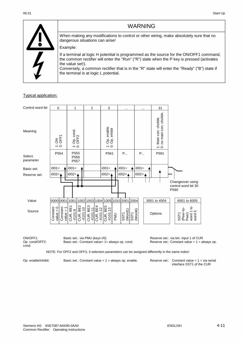
06.01 Start-Up
Siemens AG 6SE7087-6AK85-0AA0 ENGLISH 4-11Common Rectifier Operating Instructions
WARNING
When making any modifications to control or other wiring, make absolutely sure that nodangerous situations can arise!
Example:
If a terminal at logic H potential is programmed as the source for the ON/OFF1 command,the common rectifier will enter the "Run" ("R") state when the P key is pressed (activatesthe value set!).Conversely, a common rectifier that is in the "R" state will enter the "Ready" ("B") state ifthe terminal is at logic L potential.
Typical application:
i001=
i002=
P554
0
i001=
i002=
P555P556P557
1 2
i001=
i002=
P561
3
i001=
i002=
P...
...
i001=
i002=
P...
...
P591
31
0000 0001 1001 1002 1003 1004 1005 1010 2001 2004
1: O
N0
: OF
F1
1: O
p. c
ond
.0
: OF
F2
1: O
p. e
nab
le0
: Op
. in
hib
it
1: M
ain
con
. ch
ckbk
.0
: no
ma
in c
on.
ch
ckb
k.
Con
stan
t-va
lue
= 0
Con
stan
t-va
lue
= 1
CU
R, B
E1
-X1
01
:9
PM
U
SS
T1
(Wo
rd1
)
3001 to 4504
Options
CU
R, B
E2
-X1
01
:10
CU
R, B
E3
-X1
01
:11
CU
R, B
E4
-X1
01
:12
CU
R, B
E5
-X1
01
:13
SS
T1
(Wo
rd4
)
Control word bit
Select.parameter
Basic set.
Reserve set.
Value
Source
Changeover using control word bit 30P590
6001 to 6005
SS
T1
(Pe
er-
to-
Pee
r)w
ord
1 t
ow
ord
5
Meaning
ON/OFF1: Basic set.: via PMU (keys I/0) Reserve set.: via bin. input 1 of CUROp. cond/OFF2: Basic set.: Constant value= 1= always op. cond. Reserve set.: Constant value = 1 = always op.cond.
NOTE: For OFF2 and OFF3, 3 selection parameters can be assigned differently in the same index!
Op. enable/inhibit: Basic set.: Constant value = 1 = always op. enable. Reserve set.: Constant value = 1 = via serialinterface SST1 of the CUR

Start-Up 06.01
4-12 ENGLISH Siemens AG 6SE7087-6AK85-0AA0Common Rectifier Operating Instructions
4.3.1.1.2 Overview of the control word (control word 1 and control word 2)
1
2
3
4
5
6
7
8
9
10
1112
13
14
15
0PMU Display
"Control word 1" (visualization parameter r550 or r967)Bit High Low Comments Source
selection0 ON OFF1 (stop) (Priority OFF 2/1) P554
1 Operating condition OFF2 (electrical) 3 sources simultaneously effective;(Priority OFF 2/1)
P555P556P557
2 always HIGH3 Operating condition Inhibit operation Firing pulse enable P5614 always High5 always High6 always High7 Acknowledge Simultaneously effective from 3
sources and PMU;Positive edge evaluation
P565P566P567
8 Inching 1 ON Inching 1 OFF Same effect as ON/OFF1 P568 1)9 Inching 2 ON Inching 2 OFF Same effect as ON/OFF1 P569 1)10 Control from the PLC No control Only effective via
CB,TB,SST1,SST/SCB11 Ud reduction requested Ud reduction inactive P571 1)12 Regenerating enabled Regenerating inhibited not relevant for an E unit P572 1)13 No fault, external 3 Fault, external 3 P573 1)14 Motoring Generating not relevant for an E unit P574 1)15 No fault, external 1 Fault, external 1 P575
17
18
19
20
21
22
23
24
25
26
2728
2930
31
16
PMU Display"Control word 2" (visualization parameter r551)Bit High Low Comments Source
selection161718 RDS (reserve data set) bit 0 (LSB) Logic operation with bit 19 P578 1)19 RDS (reserve data set) bit 1 (MSB) Logic operation with bit 18 P579 1)20212223 12-pulse mode selected No 12-pulse mode P583 1)242526 No fault, external 2 Fault, external 2 P58627 Slave common rectifier Master common rectifier Changeover Ud/Id control P58728 No alarm, external 1 Alarm, external 1 P588
29 No alarm, external 2 Alarm, external 2 P589
30 Reserve setting forsetpoints and control word
Basic setting for setpointsand control word
P590
31 HS checkback signal No HS checkback signal Can only connected at the converterterm. strip or SCB
P591
1) This bit has a different meaning for the common rectifier as for the converter

06.01 Start-Up
Siemens AG 6SE7087-6AK85-0AA0 ENGLISH 4-13Common Rectifier Operating Instructions
4.3.1.1.3 Selecting the source for control word 1 (bit 0-7)
Bit 0 1 2 3 4 5 6 7Selection P. basic setting 554.1 555 to 557.1 561.1 565 to 567.1
Selection P. reserve setting 554.2 555 to 557.2 561.2 565 to 567.2
Value Source
0000 Constant value = 0 x x xG/R0001 Constant value = 1 xG/R xG/
R
1001 CUR, BE1, -X101:9 xR x x x1002 CUR, BE2, -X101:10 x xR for 555 x x1003 CUR, BE3, -X101:11 x x x xR for 5651004 CUR, BE4, -X101:12 x x x x1005 CUR, BE5, -X101:13 x x x x
1010 PMU xG xG for 555 1)
2001 SST1 (PMU -X300 or -X100:1...5)Word1
x x x xG/R for 567
2004 SST1 (PMU -X300 or -X100:1...5)Word4
OPTIONS
3001 CB/TB (Word1) x x x x3004 CB/TB (Word4)
4101 SCI 1 and 2, Slave 1,BE1 x x x x4102 BE2 x x x x ... Consecutively to x x x x4110 BE10 x x x x4111 only SCI 2, Slave 1,BE11 x x x x4112 BE12 x x x x ... Consecutively to x x x x4116 BE16 x x x x
4201 SCI 1 and 2, Slave 2,BE1 x x x x4202 BE2 x x x x ... Consecutively to x x x x4210 BE10 x x x x4211 only SCI 2, Slave 2,BE11 x x x x4212 BE12 x x x x ... Consecutively to x x x x4216 BE16 x x x x
4501 SCB-SST (USS /Peer-t-Peer) Word1 x x x x4504 SCB-SST (USS /Peer-t-Peer) Word4
6001 SST2 (PTP1, A2-X117:1..5) Word 1 x x x x ... Consecutively to x x x x6005 SST2 (PTP1, A2-X117:1..5) Word 5 x x x x
x: Value can be assigned for the selection parameters (BE can only be assigned once in the same index of allselection parameters!)
1) Value 1010 cannot be set, but reset is always possible from PMU.
Factory setting: xG: for basic setting with P077=0xR: for reserve setting with P077=0

Start-Up 06.01
4-14 ENGLISH Siemens AG 6SE7087-6AK85-0AA0Common Rectifier Operating Instructions
4.3.1.1.4 Selecting the source for control word 1 (bit 8-15)
Bit 8 9 10 11 12 13 14 15Selection P. basic setting 568.1 569.1 571.1 572.1 573.1 574.1 575.1
Selection P. reserve setting 568.2 569.2 571.2 572.2 573.2 574.2 575.2
Value Source
0000 Constant value = 0 xG/R xG/R xG/R x xG/R0001 Constant value = 1 x xG/R xG/R xG/R
1001 CUR, BE1, -X101:9 x x x x x x x1002 CUR, BE2, -X101:10 x x x x x x x1003 CUR, BE3, -X101:11 x x x x x x x1004 CUR, BE4, -X101:12 x x x x x x x1005 CUR, BE5, -X101:23 x x x x x x x
1010 PMU
2001 SST1 (PMU -X300 or -X100:1...5)Word1
x x x x x x x
2004 SST1 (PMU -X300 or -X100:1...5)Word4
OPTIONS
3001 CB/TB (Word1) x x x x x x x3004 CB/TB (Word4)
4101 SCI 1 and 2, Slave 1,BE1 x x x x x x x4102 BE2 x x x x x x x ... Consecutively to x x x x x x x4110 BE10 x x x x x x x4111 only SCI 2, Slave 1,BE11 x x x x x x x4112 BE12 x x x x x x x ... Consecutively to x x x x x x x4116 BE16 x x x x x x x
4201 SCI 1 and 2, Slave 2,BE1 x x x x x x x4202 BE2 x x x x x x x ... Consecutively to x x x x x x x4210 BE10 x x x x x x x4211 only SCI 2, Slave 2,BE11 x x x x x x x4212 BE12 x x x x x x x ... Consecutively to x x x x x x x4216 BE16 x x x x x x x
4501 SCB-SST (USS /Peer-t-Peer) Word1 x x x x x x x4504 SCB-SST (USS /Peer-t-Peer) Word4
6001 SST2 (PTP1, A2-X117:1..5) Word 1 x x x x x x x ... Consecutively to x x x x x x x6005 SST2 (PTP1, A2-X117:1..5) Word 5 x x x x x x x
x: Value can be assigned for the selection parameters
Factory setting: xG: for basic setting with P077=0xR: for reserve setting with P077=0

06.01 Start-Up
Siemens AG 6SE7087-6AK85-0AA0 ENGLISH 4-15Common Rectifier Operating Instructions
4.3.1.1.5 Selecting the source for control word 2 (bit 16-23)
Bit 16 17 18 19 20 21 22 23Selection P. basic setting 578.1 579.1 583.1
Selection P. reserve setting 578.2 579.2 583.2
Value Source
0000 Constant value = 0 xG/R xG/R xG/R0001 Constant value = 1 x x x
1001 CUR, BE1, -X101:9 x x x1002 CUR, BE2, -X101:10 x x x1003 CUR, BE3, -X101:11 x x x1004 CUR, BE4, -X101:12 x x x1005 CUR, BE5, -X101:13 x x x
1010 PMU
2001 SST1 (PMU -X300 or -X100:1...5)Word1
2004 SST1 (PMU -X300 or -X100:1...5)Word4
x x x
OPTIONS
3001 CB/TB (Word1)3004 CB/TB (Word4) x x x
4101 SCI 1 and 2, Slave 1, BE1 x x x4102 BE2 x x x ... Consecutively to x x x4110 BE10 x x x4111 only SCI 2, Slave 1, BE11 x x x4112 BE12 x x x ... Consecutively to x x x4116 BE16 x x x
4201 SCI 1 and 2, Slave 2, BE1 x x x4202 BE2 x x x ... Consecutively to x x x4210 BE10 x x x4211 only SCI 2, Slave 2, BE11 x x x4212 BE12 x x x ... Consecutively to x x x4216 BE16 x x x
4501 SCB-SST (USS /Peer-t-Peer) Word14504 SCB-SST (USS /Peer-t-Peer) Word4 x x x
6001 SST2 (PTP1, A2-X117:1..5) Word 1 x x x ... Consecutively to x x x6005 SST2 (PTP1, A2-X117:1..5) Word 5 x x x
x: Value can be assigned for the selection parameters
Factory setting: xG: for basic setting with P077=0xR: for reserve setting with P077=0

Start-Up 06.01
4-16 ENGLISH Siemens AG 6SE7087-6AK85-0AA0Common Rectifier Operating Instructions
4.3.1.1.6 Selecting the source for control word 2 (bit 24-31)
Bit 24 25 26 27 28 29 30 31Selection P. basic setting 586.1 587.1 588.1 589.1 590 591
Selection P. reserve setting 586.2 587.2 588.2 589.2 590 591
Value Source
0000 Constant value = 0 xG/R x0001 Constant value = 1 xG/R x xG/R xG/R x X
1001 CUR, BE1, -X101:9 x x x x x x1002 CUR, BE2, -X101:10 x x x x x x1003 CUR, BE3, -X101:11 x x x x x x1004 CUR, BE4, -X101:12 x x x x x x1005 CUR, BE5, -X101:13 x x x x X x
1010 PMU
2001 SST1 (PMU -X300 or -X100:1...5)Word1
2004 SST1 (PMU -X300 or -X100:1...5)Word4
x x x x x
OPTIONS
3001 CB/TB, Word13004 CB/TB, Word4 x x x x x
4101 SCI 1 and 2, Slave 1,BE1 x x x x x x4102 BE2 x x x x x x ... Consecutively to x x x x x x4110 BE10 x x x x x x4111 only SCI 2, Slave 1,BE11 x x x x x x4112 BE12 x x x x x x ... Consecutively to x x x x x x4116 BE16 x x x x x x
4201 SCI 1 and 2,Slave 2,BE1 x x x x x x4202 BE2 x x x x x x ... Consecutively to x x x x x x4210 BE10 x x x x x x4211 only SCI 2, Slave 2,BE11 x x x x x x4212 BE12 x x x x x x ... Consecutively to x x x x x x4216 BE16 x x x x x x
4501 SCB-SST (USS /Peer-t-Peer) Word14504 SCB-SST (USS /Peer-t-Peer) Word4 x x x x x
6001 SST2 (PTP1, A2-X117:1..5) Word 1 x x x x x ... Consecutively to x x x x x6005 SST2 (PTP1, A2-X117:1..5) Word 5 x x x x x
x: Value can be assigned for the selection parameters
Factory setting: X: for P590 / P591xG: for basic setting with P077=0xR: for reserve setting with P077=0

06.01 Start-Up
Siemens AG 6SE7087-6AK85-0AA0 ENGLISH 4-17Common Rectifier Operating Instructions
4.3.1.1.7 Significance of control word (1 and 2) commands
The status of the rectifier/regenerating unit can be read in the operating display r000: e.g. READY-TO-SWITCH-ON r000=009
The function sequences are described in the sequence in which they are realized.
Bit 0: ON command (↑↑↑↑ "ON")
The command is executed with a positive edge change from L to H (L → H) only in the READY-TO-SWITCH-ON(009).
After the command has been accepted:
♦ Changeover to the status WAIT FOR LINE VOLTAGE (010)The main contactor is closed.
♦ Changeover to the status READY STATUS(011)
♦ Changeover to the status TEST PHASE (012)Takes place only if thyristor or ground-fault test (P353,P354) selected.
♦ Changeover to the RUN status(014)Pre-charging is carried out, followed by normal operation.
Bit 0: OFF1 command (L "OFF1")
The OFF1 command (stop) is executed with an L signal.
After the command has been accepted:
♦ The DC link discharges itself until the link circuit voltage has fallen to 20% of 1.35*P071.The firing pulses are then inhibited and the main contactor (if installed) drops out.If the OFF1 command is removed again (ON command) during the discharge process, the latter isinterrupted and changeover is made again to the RUN (014) status.
♦ If the rectifier/regenerating unit is in the READY status, the firing pulses are disabled and the main contact, ifinstalled, drops out.
♦ If there is no OFF2 command:Changeover to the READY TO SWITCH ON status (009)
Bit 1: OFF2 command (L "OFF2")
The OFF2 command (electrical) is realized with an L signal.
After the command has been accepted:
♦ The firing pulses are inhibited and the main contact drops out
♦ Changeover into the SWITCH-ON INHIBIT status(008)
NOTE
The OFF2 command is simultaneously effective from three sources (P555, P556 and P557)!
NOTE
Priority of the OFF commands OFF2 > OFF1

Start-Up 06.01
4-18 ENGLISH Siemens AG 6SE7087-6AK85-0AA0Common Rectifier Operating Instructions
Bit 3: Run enable command (H "Run enable")
The RUN ENABLE command (firing pulse enable) is implemented with an H signal.
After the command has been accepted:
♦ If the READY status (011) still applies.Changeover to the RUN status (014); the firing pulses are enabled and the voltage setpoint is approachedover the pre-charging ramp.
Bit 3: Run inhibit command (L "Run inhibit")
The RUN INHIBIT command (firing pulses disabled) is implemented with an L signal.
After the command has been accepted:
♦ If the RUN status (014) applies:Changeover to the READY status (01); the firing pulses are inhibited.
Bit 4 to 6: reserved
Bit 7: Acknowledge command (↑↑↑↑ "Acknowledge")
The command is executed with a positive edge change from L to H (L → H) only in the FAULT status (007).
After the command has been accepted:
♦ All actual faults are deleted after having been previously transferred into the diagnostics memory
♦ If no faults are present:The drive changes into the status SWITCH-ON INHIBIT (008)
♦ If actual faults are present:The drive remains in the FAULT status (007).
NOTE
The acknowledge command is simultaneously effective from three sources (P565, P566 and P567) andalways from the PMU!
Bit 8: Inching 1 ON command (↑↑↑↑ "Inching 1 ON")
The command is executed with a positive edge change from L to H (L → H) only in the READY-TO-SWITCH-ONstatus (009).
After the command has been accepted
♦ an ON command is automatically executed (description, refer to control word bit 0).
Bit 8: Inching 1 OFF command (L "Inching 1 OFF")
The command is executed with an L signal.
After the command has been accepted:
♦ An OFF 1 command is automatically executed (description, refer to control word bit 0).
Bit 9: Inching 2 ON command (↑↑↑↑ "Inching 2 ON")
The command is executed with a positive edge change from L to H (L → H) only in the READY-TO-SWITCH-ONstatus (009).
After the command has been accepted
♦ an ON command is automatically executed (description, refer to control word bit 0).

06.01 Start-Up
Siemens AG 6SE7087-6AK85-0AA0 ENGLISH 4-19Common Rectifier Operating Instructions
Bit 9: Inching 2 OFF command (L "Inching 2 OFF")
The command is executed with an L signal.
After the command has been accepted:
♦ An OFF 1 command is automatically executed (description, refer to control word bit 0).
Bit 10: Control from the PLC command (H "Control from the PLC")
The command is executed with an H signal
Process data PZD (control word, setpoints) originating from a PLC which were sent via the SST1 interface ofCU1, the CB/TB interface (option) and the SST/SCB interface (option), are only evaluated if the command wasaccepted.
♦ If several interfaces are operational, only the process data of the interfaces are evaluated, which transmit theH signal.
♦ For an L signal, the last values are retained in the appropriate dual port RAM of the interface.
An H signal appears in the visualization parameter r550 "control word 1", if one of the interfaces transmits an Hsignal!
Bit 11: Ud reduction command (H "Ud reduction requested")
The command is executed with an H signal.
After the command has been accepted:
♦ The DC link voltage setpoint drops to the value set with P318:
%00.100
318PU35.1intSetpo ** rectifier,Supply=
If the value of P330 is even, Ud setpoint lowering takes place abruptly. If it is odd, the setpoint is rampeddown according to the discharge time in P330.
♦ The DC link should now discharge.
♦ When the DC link voltage drops below the following threshold value
071P35.1%100
%2
%00.100
318PU35.1 **** rectifier,Supply +
the message "Ud reduced" (status word 1, bit 13) is issued.
♦ The appearance of a trailing edge of the Ud reduction command causes the output of the ramp-up/returnelement (precharging time P329) to be set to the current value of DC link voltage so that the DC link voltagesetpoint can ramp up again from this value.
♦ The L signal of the Ud reduction command causes the "Ud reduced" message (status word 1, bit 13) to beheld low (regardless of the DC link voltage level)
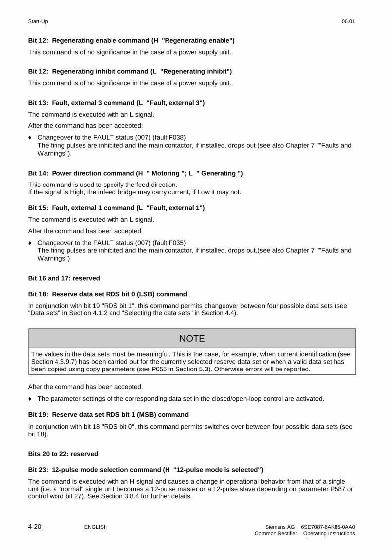
Start-Up 06.01
4-20 ENGLISH Siemens AG 6SE7087-6AK85-0AA0Common Rectifier Operating Instructions
Bit 12: Regenerating enable command (H "Regenerating enable")
This command is of no significance in the case of a power supply unit.
Bit 12: Regenerating inhibit command (L "Regenerating inhibit")
This command is of no significance in the case of a power supply unit.
Bit 13: Fault, external 3 command (L "Fault, external 3")
The command is executed with an L signal.
After the command has been accepted:
♦ Changeover to the FAULT status (007) (fault F038)The firing pulses are inhibited and the main contactor, if installed, drops out (see also Chapter 7 ""Faults andWarnings").
Bit 14: Power direction command (H " Motoring "; L " Generating ")
This command is used to specify the feed direction.If the signal is High, the infeed bridge may carry current, if Low it may not.
Bit 15: Fault, external 1 command (L "Fault, external 1")
The command is executed with an L signal.
After the command has been accepted:
♦ Changeover to the FAULT status (007) (fault F035)The firing pulses are inhibited and the main contactor, if installed, drops out.(see also Chapter 7 ""Faults andWarnings")
Bit 16 and 17: reserved
Bit 18: Reserve data set RDS bit 0 (LSB) command
In conjunction with bit 19 "RDS bit 1", this command permits changeover between four possible data sets (see"Data sets" in Section 4.1.2 and "Selecting the data sets" in Section 4.4).
NOTE
The values in the data sets must be meaningful. This is the case, for example, when current identification (seeSection 4.3.9.7) has been carried out for the currently selected reserve data set or when a valid data set hasbeen copied using copy parameters (see P055 in Section 5.3). Otherwise errors will be reported.
After the command has been accepted:
♦ The parameter settings of the corresponding data set in the closed/open-loop control are activated.
Bit 19: Reserve data set RDS bit 1 (MSB) command
In conjunction with bit 18 "RDS bit 0", this command permits switches over between four possible data sets (seebit 18).
Bits 20 to 22: reserved
Bit 23: 12-pulse mode selection command (H "12-pulse mode is selected")
The command is executed with an H signal and causes a change in operational behavior from that of a singleunit (i.e. a "normal" single unit becomes a 12-pulse master or a 12-pulse slave depending on parameter P587 orcontrol word bit 27). See Section 3.8.4 for further details.

06.01 Start-Up
Siemens AG 6SE7087-6AK85-0AA0 ENGLISH 4-21Common Rectifier Operating Instructions
Bits 24 and 25: reserved
Bit 26: Fault, external 2 command (L "Fault, external 2")
The command is recognized with an L signal and does not become active until the pre-charging time (P329) andan additional time delay of 300 ms has elapsed when the operating mode RUN is active. During formation(P052=20) or circuit identification (P052=21), the command is ineffective.
After the command has been accepted
♦ Changeover to the FAULT status (007) (fault F036)The firing pulses are inhibited and the main contactor, if installed, drops out (see also Chapter 7 "Faults andWarnings").
Bit 27: Master/slave changeover (H "Slave common rectifier"/L "Master common rectifier ")
The command switches between slave and master mode.
Slave common rectifier: The closed-loop control operates with an external DC link current setpointEven when a thyristor test is selected (P353=1, 2 or 3) if Ud > 5% it does not wait instate o012 and the thyristor test is not carried out.
Master common rectifier: The closed-loop control operates with an external DC link current setpoint
Bit 28: Alarm, external 1 command (L "Alarm, external 1")
The command is executed with an L signal.
After the command has been accepted
♦ The operating status is retained. An alarm message (A015) is output (also refer to Section 7 "Fault and AlarmMessages")
Bit 29: Alarm, external 2 command (L "Alarm, external 2")
The command is executed with an L signal.
After the command has been accepted:
♦ The operating status is retained. An alarm message (A015) is output (also refer to Section 7 " Fault andAlarm Messages ")
Bit 30: Selection, basic/reserve setting command (L "Basic setting / H "Reserve setting")
The command activates the BASIC SETTING with an L signal and the RESERVE SETTING with an H signal
After the command has been accepted:
♦ The parameter settings of the basic or reserve setting for the control word itself, the setpoint channel, and theclosed-loop control are activated (see "Data sets" in Section 4.1.2 and "Selecting the data sets" in Section4.4).
Bit 31: Main contactor checkback signal command (H "Main contactor checkback signal")
This command permits you to include an auxiliary contact of the main contactor in the unit control circuit (an Hsignal implies that the main contactor has picked up).
After the command has been accepted:
♦ An operating status > o010 is permitted

Start-Up 06.01
4-22 ENGLISH Siemens AG 6SE7087-6AK85-0AA0Common Rectifier Operating Instructions
4.3.1.2 Status word (status word 1 and status word 2)
4.3.1.2.1 Introduction and application example
Status words 1 (bits 0 to 15) and 2 (bits 16 to 31) issue messages and commands from the common rectifier toexternal destinations.
Their particular status can be read-out via parameters r552 or r968 (status word 1) and r553 (status word 2).An overview is provided in Section 4.3.1.2.2 "Overview of the status word".The significance of the possible messages and commands to the outside is described in Section 4.3.1.2.4"Significance of the status word messages".Each status word bit is assigned a selection parameter, which defines, to which destination this bit is sent (referto Section 4.3.1.2.2, right-hand column).The selection parameters for the destinations are indexed twice as follows:
Index: i001 Selecting a terminal on the CU / PEU board (basic converter)i002 Selecting a terminal on the SCI 1/2 board (option)
An overview of the possible destinations, which are assigned fixed values, is provided in Section 4.3.1.2.3"Selecting the destinations for the status word".
NOTE
For the output of faults, alarms and switch-on inhibit of the status word (HIGH active) via the terminal strip,then these are LOW active at the terminals (binary outputs) (i.e.: the relay drops out)!This is also true for possible option boards!Also refer to Section 4.3.3 "Binary outputs"
Example:
i001=
i002=
P600
0
P601 P602 P603 P... P... P631
0000 1001 1002
P600P600
i001=
i002=
1
i001=
i002=
2
i001=
i002=
3
i001=
i002=
i001=
i002=
i001=
i002=
... ... 31
0000 4101 ... 4112 4201 ... 4205 ... 4212
Status word bit
Selectparameter
Term. on CUR
1: R
ead
y0
: n.
rea
dy
1: F
aul
t0
: no
fau
lt
1: P
rech
. ac
tive
0: P
rech
. no
t ac
tive
1: R
un
0: P
uls
e.
inh
ibit
1: R
ead
y to
sw
itch-
on
0: n
.rea
dy
to s
witc
h-o
n
Term on SCI 1/2
Meaning
no
de
st.
CU
R, B
A1
-X1
04
:17
/18
CU
R, B
A2
-X1
04
:19
/20
Value
Dest.
Index 1Terminal on CUR
no
de
st.
SC
I,S
lave
2B
A1
2
SC
I,S
lave
1B
A1
SC
I,S
lave
1B
A1
2
SC
I,S
lave
2B
A1
SC
I,S
lave
2B
A5
Index 2Terminal on SCI 1/2
(Option)
"Run" signal: - at terminal -X104:19/20 of the CUR
- at terminal of the binary output 5 of the SCI (option),which is coded as slave 2

06.01 Start-Up
Siemens AG 6SE7087-6AK85-0AA0 ENGLISH 4-23Common Rectifier Operating Instructions
4.3.1.2.2 Overview of the status word (status word 1 and status word 2)
1
2
3
4
5
6
7
8
9
10
1112
13
14
15
0PMU Display
"Status word 1" (visualization parameter r552 or r968)Bit High Low Comments Dest.
selection0 Ready-to-switch-on Not ready to switch on P600
1 Ready Not ready P601
2 Run Firing pulses inhibited P602
3 Fault No fault Inverted for terminal strips! P603
4 No OFF 2 OFF2 P604
5 always High6 Switch-on inhibit No switch-on inhibit Inverted for terminal strips! P606
7 Alarm No alarm Inverted for terminal strips! P607
8 No setpt. act. val. deviation Setpt. act. value deviation Can be parameterized P608
9 PZD control requested always "High"(for CB,TB,SST1,SST/SCB)
10 Regenerating ready Regenerating not ready P610 1)11 Fault, undervoltage No undervoltage fault Inverted for terminal strips! P611
12 Main contactor energized Main contactor notenergized
Can only be connector forterminals CUR or SCI!
P612
13 Ud reduced Ud not reduced P613 1)14 Motoring Generating not relevant for an E unit P614 1)15
17
18
19
20
21
22
23
24
25
26
2728
2930
31
16
PMU Display"Status word 2" (visualization parameter r553)Bit High Low Comments Dest.
selection161718 Current active Current limit not active Inverted for terminal strips! P618 1)19 Fault, external 1 No fault, external 1 Inverted for terminal strips! P619
20 Fault, external 2 No fault, external 2 Inverted for terminal strips! P620
21 Alarm, external No alarm, external Inverted for terminal strips! P621
22 Alarm i2t power sections No alarm, i2t power section Inverted for terminal strips! P622
23 Fault, overtemp., p.s. No fault, overtemp. p.s. Inverted for terminal strips! P623
24 Alarm, overtemp., p.s. No alarm, overtemp., p.s. Inverted for terminal strips! P624
25262728293031 Pre-charging active Pre-charging not active P631
1) The meaning of this bit is different for the common rectifier than for the converter

Start-Up 06.01
4-24 ENGLISH Siemens AG 6SE7087-6AK85-0AA0Common Rectifier Operating Instructions
4.3.1.2.3 Selecting the destinations for the status word (bits 0 - 31)
For the selection parameters P600 to P631, in which the destination of the appropriate bit can be specified, thenthe indices are uniformly assigned as follows:
Index i001 Selecting a terminal on the CUR board (basic converter)i002 Selecting a terminal on the SCI 1/2 board (option)
Index i001 Selecting a terminal on the CUR board (basic converter)
Value Destination
0000 No destination Factory setting, except P6031001 CUR, BA1, -X104:17/18,1002 CUR, BA2, -X104:19/20, Factory setting, for P603
Index i002 Selecting a terminal on the SCI 1/2 board (option)
Value Destination
0000 No destination Factory setting4101 SCI 1 and 2,Slave 1, BA14102 BA24103 BA34104 BA44105 BA54106 BA64107 BA74108 BA84109 only SCI 2,Slave 1, BA94110 BA104111 BA114112 BA124201 SCI 1 and 2,Slave 2, BA14202 BA24203 BA34204 BA44205 BA54206 BA64207 BA74208 BA84209 only SCI 2,Slave 2, BA94210 BA104211 BA114212 BA12

06.01 Start-Up
Siemens AG 6SE7087-6AK85-0AA0 ENGLISH 4-25Common Rectifier Operating Instructions
4.3.1.2.4 Significance of the status word messages
NOTE
When faults, alarms and switch-on inhibit of the status word are output (HIGH active) via the terminal strip,then these are LOW active at the terminal strips (binary outputs) (i.e.: relay drops out)!
This is also valid for possible option boards!Also refer to Section 4.3.3 "Binary outputs"
Bit 0: Signal, "Ready to switch-on" (H)
An H signal indicates that the operating status SWITCH-ON INHIBIT (008) or READY-TO-SWITCH-ON (009) isavailable. The firing pulses are inhibited.
Bit 1: Signal, "Ready" (H)
H An H signal, indicates that the operating status READY (011) or PRE-CHARGING (010) is available. The firingpulses are still inhibited.
Bit 2: Signal, "Run" (H)
An H signal indicates that the operating status RUN (014) is available. The firing pulses are enabled and theoutput terminals are live.
Bit 3: Signal, "Fault" (H)
An H signal indicates that the operating status FAULT (007) is available. If the fault is output at a terminal strip(CUR, SCI1/2) an L signal appears there for this fault message.
Bit 4: Signal, "OFF2" (L)
An L signal indicates that an OFF2 command is present via the control word (bit 1).
Bit 5: reserved
Bit 6: Signal, "Switch-on inhibit" (H)
An H signal indicates that the operating status SWITCH-ON INHIBIT (008) is present. The message remains aslong an OFF2 command is applied over the control word (bit 1) and/or an ON command is still applied thecontrol word (bit 0) (edge evaluation).If the message is output at a terminal strip (CUR, SCB1) an L signal appears there for this message.
Bit 7: Signal, "Alarm" (H)
An H signal indicates that an alarm (Axxx) is present. If the alarm is output at the terminal strip (CUR, SCB1), anL signal appears there for this alarm.
Bit 8: Signal, "Setpoint/actual-value deviation" (L)
The L signal indicates that the absolute value of the difference between the Ud setpoint and the Ud actual valueis greater than or equal to a programmable deviation (P517 "Setpoint/actual-value deviation Ud" for longer thanthe "Setpoint/actual-value deviation time" (P518). The bit is again set high as soon as the absolute value of thedifference between the Ud setpoint and the Ud actual value is less than the deviation (P517).
Bit 9: Signal, "PZD control requested" (H)
An H signal is always present.
Bit 10: Message, "Regenerating ready" (H)
Always L in the case of a power supply unit.
Bit 11: Message, "Fault" (reserved, L)
An L signal is always present. If the fault signal is output to a terminal block (CUR, SCI 1/2), an L signal appearsthere for this fault.
Bit 12: Signal, "Main contactor energized" (H)
This message is identical to the status of the relay contact at terminals 9-4/5 with which a main contactor can bedriven.

Start-Up 06.01
4-26 ENGLISH Siemens AG 6SE7087-6AK85-0AA0Common Rectifier Operating Instructions
Bit 13: Message, "Ud reduced" (H)
An H signal indicates that the DC link voltage has been reduced below the following value:
071P35.1%100
%2
%100
318PU35.1 **** rectifier,Supply +
The signal changes from H to L when the DC link voltage exceeds the following threshold:
071P35.1%100
319P%2
%100
318PU35.1 **** rectifier,Supply
+
+
L signal ("Ud not reduced") is also output for as long as control word 1, Bit 11=0 ("No Ud reduction requested") ispending and for as long as no Ud reduction command for current-dependent Ud reduction has been generatedinternally.
Bit 14: Message, " Motoring mode" (H)
The High signal indicates that the infeed bridge is live or is ready to be made live.
Message, " Generating mode" (L)
The Low signal indicates that the infeed bridge is not live.
Bits 15 to 17: reserved
Bit 18: Message, "Current limit active" (L)
An L signal indicates that the common rectifier is operating at the current limit. If the message is output at aterminal (CUR, SCB1), an L signal appears there for this message
Bit 19: Signal, "Fault, external 1" (H)
An H signal indicates that a "Fault, external 1" is present in control word bit 15. If this fault is output at a terminalstrip (CUR, SCB1), an L signal appears there for this fault signal.
Bit 20: Signal, "Fault, external 2" (H)
An H signal indicates that a "Fault, external 2" is present in control word bit 26. If this fault is output at a terminalstrip (CUR, SCB1), an L signal appears there for this fault signal.
Bit 21: Signal, "External alarm" (H)
An H signal indicates that an "Alarm, external 1" is present in control word bit 28, or an "alarm, external 2" incontrol word, bit 29.If this fault is output at a terminal strip (CUR, SCB1), an L signal appears there for this fault signal.
Bit 22: Signal, "Alarm I2t power section" (H)
H signal indicates that the "I2t alarm power section" (A025) is present. Also refer to Section 7 "Fault and AlarmMessages".
If this alarm is output at a terminal strip (CUR, SCB1), an L signal appears there for this fault signal.
Bit 23: Signal "Overtemperature fault signal power section (H)
An H signal indicates that an "Power section temperature too high" fault (F023) is present. Also refer to Section 7"Fault and Alarm Messages".
If this fault is output at a terminal strip (CUR, SCB1), an L signal appears there for this fault signal.
Bit 24: Signal "Overtemperature alarm power section" (H)
An H signal indicates that the "Power section temperature too high" alarm (A022) is present. Also refer toSection 7 "Fault and Alarm Messages". If this fault is output at a terminal strip (CUR, SCB1), an L signal appearsthere for this fault signal.
Bits 25 to 30: reserved
Bit 31: Signal, "Pre-charging active" (H)
An H signal indicates that the DC link has been charged following a successful ON command.

06.01 Start-Up
Siemens AG 6SE7087-6AK85-0AA0 ENGLISH 4-27Common Rectifier Operating Instructions
4.3.1.3 Setpoints
The only possible setpoint selection that can be programmed on a common rectifier is the selection of the Idsetpoint for a common rectifier in slave mode (e.g. the slave common rectifier in 12-pulse operation) usingparameter(See also Chapter 5 "Parameter list")
The control word command can be used for effecting the changeover:"Basic and reserve settings"See Section 4.4 "Function diagrams"
The source for the setpoint is defined using values:
Value entry in Index1 i001 active when "basic setting" selected" (control word)Index2 i002 active when "reserve setting" selected (control word)
Value assignment for P486 "Source Id-setpoint":
Value Source
0000 Constant setpoint = 0 Factory setting: P486 i001, i0022002 SST1 (PMU -X300 or -X100:1...5) Word22003 Word32004 Word4 ⇐ only if word 4 is not assigned for "control
word 2 with 2004 (Section 4.3.1.1) ... consecutively to2016 Word16
OPTIONS3002 CB/TB Word23003 Word33004 Word4 ⇐ only if word 4 is not assigned for "control
word 2 with 3004 (Section 4.3.1.1) ... consecutively to3016 Word16)4101 SCB1 with SCI 1,Slave1, analog input AE14102 AE24103 AE34201 SCB1 with SCI 1,Slave2, analog input AE14202 AE24203 AE34501 SCB-SST (only Peer to Peer, Word1) ⇐ only if word 1 is not assigned for "control
word 1 with 4501 (Section 4.3.1.1)
4502 USS /Peer to Peer, Word24503 USS /Peer to Peer, Word34504 USS /Peer to Peer, Word4 ⇐ only if word 4 is not assigned for "control
word 2 with 4504 (Section 4.3.1.1)4505 USS /Peer to Peer, Word54506 only USS, Word6 ... consecutively to4516 only USS, Word66002 SST2 (PTP1, A2-X117:1..5) Peer-to-Peer, Word26003 SST2 (PTP1, A2-X117:1..5) Peer-to-Peer, Word36004 SST2 (PTP1, A2-X117:1..5) Peer-to-Peer, Word46005 SST2 (PTP1, A2-X117:1..5) Peer-to-Peer, Word5

Start-Up 06.01
4-28 ENGLISH Siemens AG 6SE7087-6AK85-0AA0Common Rectifier Operating Instructions
4.3.1.4 Actual values
All available parameter numbers (0 to 999) can be entered into the actual value parameters, sorted according todestinations (refer to the following).The parameter value of the entered parameter number is output at the selected destination.
Note: - When specifying parameter numbers, which are indexed, the value of the first index(.i001) is always output!
- When specifying "0", no output is made to the appropriate destination!
Destinations:
P655 "CUR-AA actual values"Output via the CUR control terminal strip (Section 3.3)Analog output 1 (-X102:14 / reference potential -X102:15)(refer to Section 4.3.5 "analog output")
P680 "SST1 actual values"Output via the basic converter interface SST1
Indices: i001 Word 01 of the telegram (PZD) ⇓ ⇓i016 Word 16 of the telegram (PZD)
(refer to Section 4.3.6.1 "basic converter interface SST1")
Destination, options:
P664 "SCI-AA actual values"Output via the SCB1 interface with SCI1(also refer to the Instruction Manual for the option boards)
Indexes: i001 Destination: Analog output 1 from slave 1i002 Destination: Analog output 2 from slave 1i003 Destination: Analog output 3 from slave 1i004 Destination: Analog output 1 from slave 2i005 Destination: Analog output 2 from slave 2i006 Destination: Analog output 3 from slave 2
P690 "SCB actual values"Output via the SCB1 interface with peer-to-peer protocol or SCB2(also refer to the Instruction Manual for the option boards)
Indexes: i001 Destination: Word 01 of the telegram (PZD) ⇓ ⇓i016 Destination: Word 16 of the telegram (PZD)
P694 "CB/TB actual values"Output via the CB or TB interface(also refer to the Instruction Manual for the option boards and Sections 4.3.6.2 "DPR")
Indexes: i001 Destination: Word 01 of the telegram (PZD) ⇓ ⇓i016 Destination: Word 16 of the telegram (PZD)
NOTE
For telegram data transfer (P680,P690,P694), it is generally necessary/practical to assign "Word 01 of thetelegram (PZD)" with status word 1 (r968 or r552)!

06.01 Start-Up
Siemens AG 6SE7087-6AK85-0AA0 ENGLISH 4-29Common Rectifier Operating Instructions
4.3.2 Binary inputs
5 binary inputs (24V) which can be parameterized at the control terminal strip (board CUR, -X101) to entercommands, external faults/alarms as well as a checkback signal to the common rectifier control word.
Connecting-up:
Refer to Section 3.3 "Control terminal strip "
Parameterization:
Refer to Section 4.3.1.1 "Control word"
Function of the binary inputs for factory setting with P077 = 0 (see Section 4.3.9.1):
Binary input 1 ON/OFF 1 command (control word bit 0)for RESERVE SETTING (binary input 5 = high state)
Binary input 2 OFF2 command "pulse inhibit" (control word bit 1)for RESERVE SETTING (binary input 5 = high state)
Binary input 3 Acknowledge (control word bit 7)for RESERVE SETTING (binary input 5 = high state)
Binary input 4 No function
Binary input 5 RESERVE/BASIC SETTING (control word bit 30)
4.3.3 Binary outputs
2 binary outputs, which can be parameterized, for the output of signals and external commands of thecommon rectifier status word.
Connecting-up:
Binary output 1 on the CUR control terminal strip (connector X104 / NO contact):Refer to Section 3.3 "Control terminal strip"
Binary output 2 on the CUR control terminal strip (connector X104 / NO contact):Refer to Section 3.3 "Control terminal strip"
Parameterization:
Refer to Section 4.3.1.2 "Status word"
Factory setting:
Binary output 1X10⁴ on the CUR
No function (relay always de-energized)
Binary output 2X10⁴ on the CUR
Fault (status word bit 3)
NOTE
When faults, alarms and switch-on inhibit of the status word (HIGH active) are output via the terminal strip,these are LOW active at the terminal strip (binary outputs) (i.e. relay drops out)!Also refer to Section 4.3.1.2 "Status word".

Start-Up 06.01
4-30 ENGLISH Siemens AG 6SE7087-6AK85-0AA0Common Rectifier Operating Instructions
4.3.5 Analog output
output actual values and other internal common rectifier quantities.Analog output: - Voltage range: ± 10V
- Resolution: 39mV (8 bits + sign)- Accuracy: ± 5%- Smoothing: 20ms- Output current: max. ± 5mA- Short-circuit proof and non-floating
Connecting-up:
Refer to "Control terminal strip", Section 3.3
Parameterization:
Also observe "Function diagram, analog output CUR", Section 4.4!
♦ Enter the parameter number (0 to 999) whose value is to output, in P655 "CUR-AA actual values".♦ Set the analog output gain factor in P656 "CUR-AA gain".
(setting range: -320.00V to +320.00V / pre-setting: +10.00V ⇔ gain of 1)♦ Set the offset in P657 "CUR-AA offset".
(setting range: -100.00V to +100.00V / pre-setting: +0.00V ⇔ no offset)
The following is obtained for the calculation from the "Function diagram, analog output CUR":
[ ][ ] [ ] [ ]VinOffsetVinainG%100
%nivalue ParameterUoff +
×=
Pre-assignment (gain of 1 and no offset): 100% = 10V
The parameter value in [%] for the appropriate parameter number can be taken from the parameter list,Chapter 5!

06.01 Start-Up
Siemens AG 6SE7087-6AK85-0AA0 ENGLISH 4-31Common Rectifier Operating Instructions
•••• Configuring examples:
Example 1: Available: P071 (line voltage) = 400 V
Required: Map the actual DC link voltage r037 between 400 and 600 V to 0.00V to+10.00 V at the analog output
♦ Connect-up parameter R037 at the analog output:P655 "CUR-AA actual values" = 037
♦ Converter the required output range in [%]:r037 should be taken from the parameter list, Section 5:Analog output: 100% = 1.35 x P071 (in this case: 1.35 x 400 V = 540 V)
Thus, the following is obtained for the range to be represented:400 V → 74.05% (Parameter value PWE1) to be represented as Uoff1 = 0.00 V600 V → 111.07% (Parameter value PWE2) to be represented as Uoff2 = +10.00 V
♦ Define gain factor P656 and offset P657:
The following is obtained from the formula shown above:
[ ] [ ] [ ]( )[ ] [ ]
[ ] [ ] [ ] [ ]
V 98.19% 100
% 74.05 V 27.03 V0
% 100
% 74.05 V 27.030V
% 100
%PWE Vfactor GainV U=V Offset
V27.03% 37
100 V10,00
% 111.07% 74.05
%100 V)10.00 V (0.00
%PWE %PWE
%100 VU VUV factor Gain
1 off1
2 1
off2 off1
−=
×−=
×−=
×−
=−
×−=
−×−=
−×−=
To be adjusted: gain: P656 = +27,03Voffset: P657 = −−−−19,98V
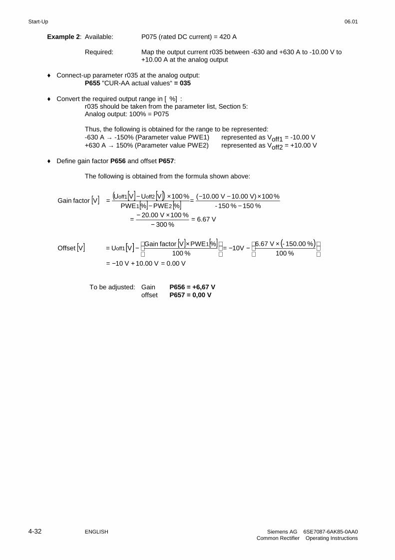
Start-Up 06.01
4-32 ENGLISH Siemens AG 6SE7087-6AK85-0AA0Common Rectifier Operating Instructions
Example 2: Available: P075 (rated DC current) = 420 A
Required: Map the output current r035 between -630 and +630 A to -10.00 V to +10.00 A at the analog output
♦ Connect-up parameter r035 at the analog output:P655 "CUR-AA actual values“ = 035
♦ Convert the required output range in [%]:r035 should be taken from the parameter list, Section 5:Analog output: 100% = P075
Thus, the following is obtained for the range to be represented:-630 A → -150% (Parameter value PWE1) represented as Voff1 = -10.00 V+630 A → 150% (Parameter value PWE2) represented as Voff2 = +10.00 V
♦ Define gain factor P656 and offset P657:
The following is obtained from the formula shown above:
[ ] [ ] [ ]( )[ ] [ ]
[ ] [ ] [ ] [ ] ( )
V 0.00 V0.001 V10
% 100
% 150.00- V 6.6710V
% 100
%PWE Vfactor GainV U=V Offset
V6.67% 300
% 100 V20.00
% 150% 150-
%100 V)10.00 V 10.00(
%PWE %PWE
%100 VU VUV factor ainG
1 off1
2 1
off2 off1
=+−=
×−−=
×−
=−
×−=
−×−−=
−×−=
To be adjusted: Gain P656 = +6,67 Voffset P657 = 0,00 V

06.01 Start-Up
Siemens AG 6SE7087-6AK85-0AA0 ENGLISH 4-33Common Rectifier Operating Instructions
4.3.6 Serial interfaces
4.3.6.1.1 Basic converter interface SST1
The USS protocol (universal serial interface) is implemented at the basic converter interface SST1.
The following documentation is available depending on the particular application of the SST1 basic converterinterface:
♦ Connection of higher-level programmable controllers with USS protocol:SIMOVERT Master DrivesUse of the serial interface with USS protocolOrder No.: 6SE7087-6CX87-4KB0
♦ Additional general comments regarding connecting-up and parameterization:
♦ Connecting-up: Also refer to "Control terminal strip" Section 3.3
NOTE
Communications can either be realized via the terminal strip of CUR-X100 (RS485 standard) or the interfaceconnector on PMU-X300 (9-pin SUB D connector / RS485 or RS232)
Only one of the two possible connections (-X100 or -X300) may be used!
NOTE
The bus terminating resistors (total 150 Ω) must be switched-in at the last bus node (slave).To realize this, jumpers of DIP-FIX switches S1 and S2 must be closed on board CUR!
♦ Parameterization:
- Defining the interface: P683 to P687- Define the process data (control word, status word, setpoints, actual values) for the interface:
Refer to "Process data" Section 4.3.1- Parametrierfreigabe: P053 oder P927
NOTE
The factory setting (refer to "Parameter list" Chapter 5) can be used if the SST1 basic converter interface is notused!
4.3.6.1.2 Basic converter interface SST2 (A2-X117), see Section 9.6, Options
4.3.6.2 Dual-Port-Ram (DPR for SCB, CB, TB)
The dual-port RAM is the internal interface on the CUR (-X107) to connect possible option boards via thebackplane bus of the electronics box (LDA bus adapter required).
Possible option boards: TB (Technology board);SCB (serial communications board); CB (Communications board).
To connect possible option boards and parameterize the interface, also refer to the Section 3.5 "Recommendedcircuits" as well as in the appropriate Instruction Manuals to the various option boards.Additional information can be taken from Sections 4.3.1.1 to 4.3.1.4 "Control word, status word, setpoints, actualvalues".

Start-Up 06.01
4-34 ENGLISH Siemens AG 6SE7087-6AK85-0AA0Common Rectifier Operating Instructions
4.3.9 Function selection (P052)
Function selection is activated via parameter P052 and permits various special functions during the start-upphase.
Access stage 2 (P051 = 2) must be enabled and the common rectifier may only be in the "Run" (R) status. Apartfrom this, P053 must be set for parameter enable (e.g. P053=6).
The following functions are available:
- Return from function selection (P052 = 0)- Generate factory setting (P052 = 1)- Initialization (MLFB setting) (P052 = 2)- Download (P052 = 3)- Hardware configuration (P052 = 4)- Drive setting (P052 = 5)- Forming (P052 = 20)- Circuit identification (P052 = 21)- Display modified parameters (P052 = 22)
The "Generate factory setting", "Forming", and "Circuit identification" functions are automatically reset oncompletion, i.e. P052 = 0 ("Return").The other functions must be manually reset!
4.3.9.1 Generate factory setting (P052 = 1 or P970 = 0)
This function is used to reset the parameter values, in accordance with a) the parameter list (dispatch status forthe unit; see Section 5, column 4) and b) parameter P077 (see below). Only the settings of parameters P070(MLFB) and P077 (type of factory setting) remain unchanged.The MLFB-dependent parameters P071, P075 and P076 are set in accordance with the type of the commonrectifier (see Section 4.3.9.2 "Initialization").The parameters dependent on P077 are set in accordance with the table shown below.In the normal case (P070=0), the values listed in the parameter list in Section 5 are used as factory settings, sothe table shown below does not have to be considered.For fast parameterization of special functions, using P077=1 to 6, an appropriate set of factory settings can beselected for certain parameters in accordance with the table shown below. In this manner, for example, certainterminals of the basic unit can be parameterized fast as sources for certain control word functions.The following table shows the factory settings for the parameters that are dependent on P077:
Para-metersdepend.
Designation ofthe parameter
Normalfactorysetting
Standardcubicle withterminals
Standardcubicle with
PMU
Standardcubicle with
OP1S
Standardcubicle with
PMU as12-pulse slave
Standardcubicle with
OP1S as12-pulse slave
on on OP1S P077= 0 P077= 1 P077= 2 P077= 4 P077= 5 P077= 6P077 Basic
(i001)Res.(i002)
Basic(i001)
Res.(i002)
Basic(i001)
Res.(i002)
Basic(i001)
Res.(i002)
Basic(i001)
Res.(i002)
Basic(i001)
Res.(i002)
P486 Src Current Setp 0 0 0 0 0 0 0 0 6002 0 6002 0P554 Src ON/OFF1 1010 1001 2001 1001 1003 1010 1003 2001 6001 1010 6001 2001P555 Src1 OFF2(electr.) 1010 1002 2001 1002 1003 1010 1003 2001 6001 1010 6001 2001P561 Src InvRelease 1 1 1 1 1 1 1 1 6001 1 6001 1P565 Src1 fault reset 0 1003 0 1003 0 0 0 0 0 0 0 0P566 Src2 fault reset 0 0 0 0 1004 0 1004 0 6001 0 6001 0P567 Src3 fault reset 2001 2001 2001 2001 0 0 2001 2001 2001 0 2001 2001P572 Src RegenRelease 1 1 1 1 1 1 1 1 6001 1 6001 1P575 Src No ExtFault1 1 1 1 1 1001 1001 1001 1001 1001 1001 1001 1001P583 Src 12-pulse mode 0 0 0 0 0 0 0 0 1 0 1 0P587 Src Master/Slave 0 0 0 0 0 0 0 0 1 0 1 0P588 Src No Ext Warn1 1 1 1 1 1002 1002 1002 1002 1002 1002 1002 1002P607 Trg Bit Warning 0 0 1001 1001 1001 1001
The factory setting for P607.002 (responsible for the optional SCI1/2 module) is not affected by P077.
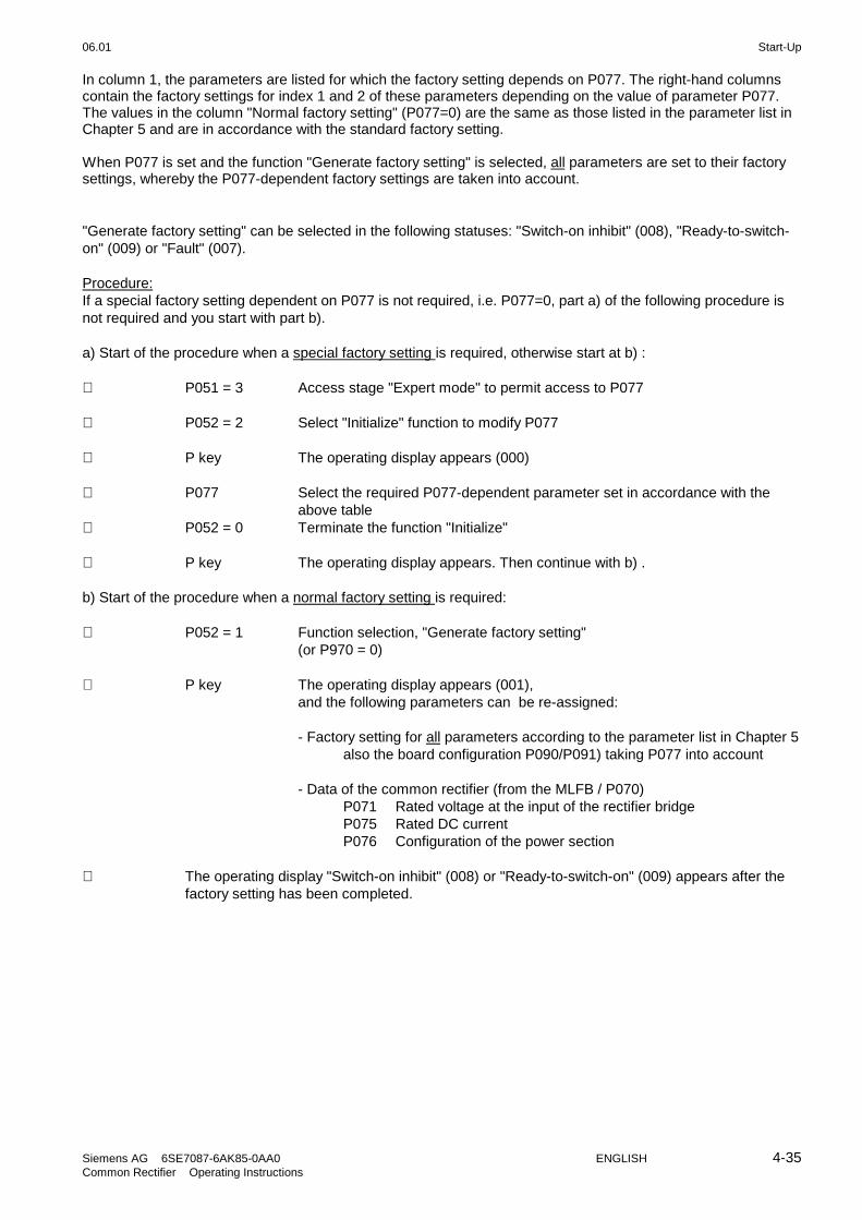
06.01 Start-Up
Siemens AG 6SE7087-6AK85-0AA0 ENGLISH 4-35Common Rectifier Operating Instructions
In column 1, the parameters are listed for which the factory setting depends on P077. The right-hand columnscontain the factory settings for index 1 and 2 of these parameters depending on the value of parameter P077.The values in the column "Normal factory setting" (P077=0) are the same as those listed in the parameter list inChapter 5 and are in accordance with the standard factory setting.
When P077 is set and the function "Generate factory setting" is selected, all parameters are set to their factorysettings, whereby the P077-dependent factory settings are taken into account.
"Generate factory setting" can be selected in the following statuses: "Switch-on inhibit" (008), "Ready-to-switch-on" (009) or "Fault" (007).
Procedure:If a special factory setting dependent on P077 is not required, i.e. P077=0, part a) of the following procedure isnot required and you start with part b).
a) Start of the procedure when a special factory setting is required, otherwise start at b) :
⇓ P051 = 3 Access stage "Expert mode" to permit access to P077
⇓ P052 = 2 Select "Initialize" function to modify P077
⇓ P key The operating display appears (000)
⇓ P077 Select the required P077-dependent parameter set in accordance with theabove table
⇓ P052 = 0 Terminate the function "Initialize"
⇓ P key The operating display appears. Then continue with b) .
b) Start of the procedure when a normal factory setting is required:
⇓ P052 = 1 Function selection, "Generate factory setting"(or P970 = 0)
⇓ P key The operating display appears (001),and the following parameters can be re-assigned:
- Factory setting for all parameters according to the parameter list in Chapter 5also the board configuration P090/P091) taking P077 into account
- Data of the common rectifier (from the MLFB / P070)P071 Rated voltage at the input of the rectifier bridgeP075 Rated DC currentP076 Configuration of the power section
⇓ The operating display "Switch-on inhibit" (008) or "Ready-to-switch-on" (009) appears after thefactory setting has been completed.

Start-Up 06.01
4-36 ENGLISH Siemens AG 6SE7087-6AK85-0AA0Common Rectifier Operating Instructions
4.3.9.2 Initialization (MLFB setting) (P052 = 2)
This function is used to change the common rectifier MLFB (type setting).The parameters P071, P075 and P076 are only set dependent on the new MLFB when changing the MLFB .
"Initialization" can be selected in the following statuses: "Switch-on inhibit" (008), "Ready-to-switch-on" (009) or"Fault" (007).
Procedure:⇓ P051 = 3 Access stage "Expert mode" to permit access to P070
⇓ P052 = 2 Function selection "Initialization"
⇓ P070 Specification of the number of the MLFB of the common rectifier (rating platedata on the unit) according to the table at the end of this Section.
⇓ P052 = 0 Terminate the function "Initialize"
⇓ P key The operating display appears and once the MLFB has been modified, thefollowing parameters are reassigned in accordance with the MLFB:
P071 Rated voltage at the input to the rectifier bridgeP075 Rated DC currentP076 Only the ones position is modified
Ones position =1: Ones position =1: only power supplyoperation possible (is set automatically for P070≥101(power supply unit))
⇓ The operating display "Switch-on inhibit" (008) or "Ready-to-switch-on" (009) appears after"Initialization" has been completed
MLFB table (see next page):
Brief description of the table columns:
PWE Parameter value (to be entered at initialization / PMU / P070)MLFB Machine-readable product designation (see rating plate)I(n) Rated DC current in A (P075)U-Kl. Voltage class, voltage rangeBF Type of construction
MLFB-table:
PWE MLFB Rated current
[A]
Supply voltage
[V]
BF
0 none 0,0 0 0
101 6SE7037-7FH85-0AA0 774,0 3AC 500-600V H
102 6SE7037-7HH85-0AA0 774,0 3AC 660-690V H
103 6SE7038-2EH85-0AA0 821,0 3AC 380-480V H
104 6SE7041-0FH85-0AA0 1023,0 3AC 500-600V H
105 6SE7041-0EH85-0AA0 1023,0 3AC 380-480V H
106 6SE7041-0HH85-0AA0 1023,0 3AC 660-690V H
107 6SE7041-3FK85-0AA0 1285,0 3AC 500-600V K
108 6SE7041-3HK85-0AA0 1285,0 3AC 660-690V K
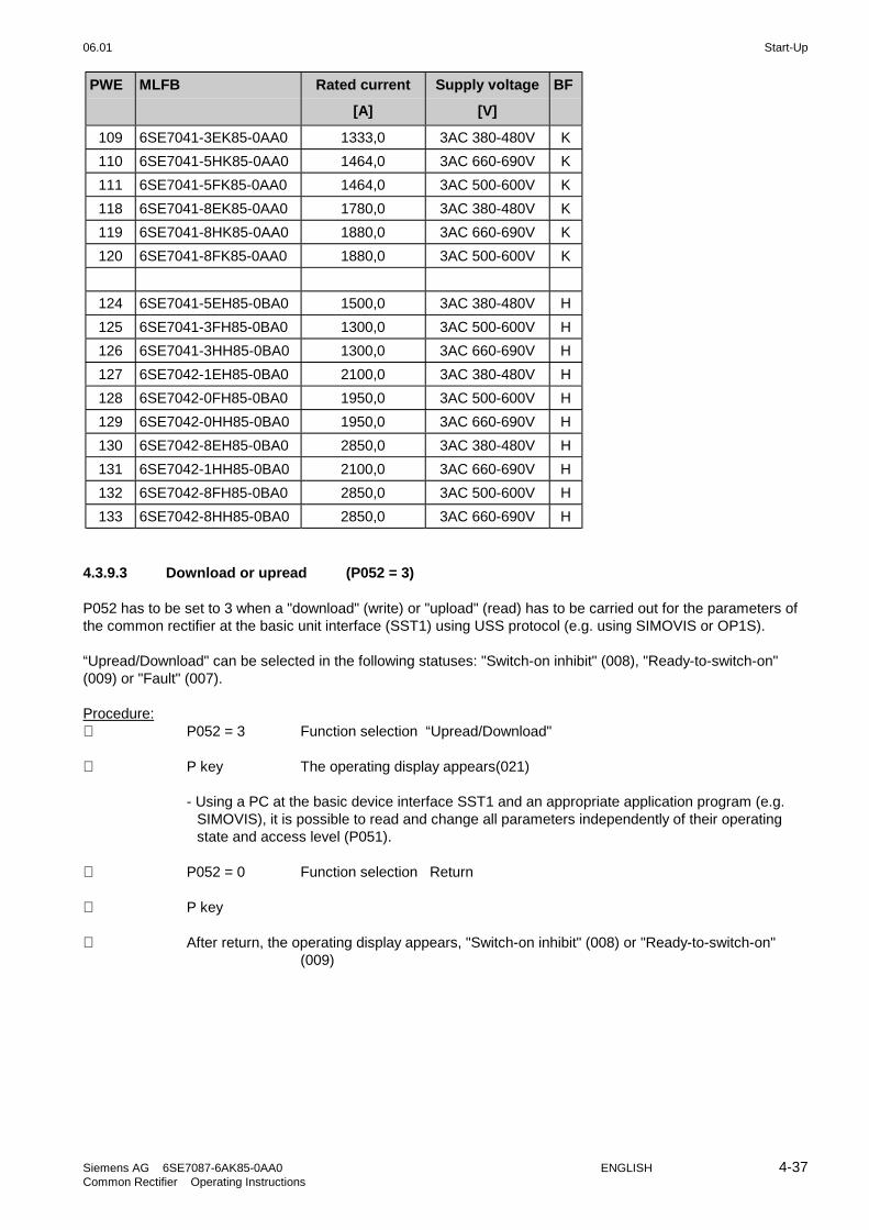
06.01 Start-Up
Siemens AG 6SE7087-6AK85-0AA0 ENGLISH 4-37Common Rectifier Operating Instructions
PWE MLFB Rated current
[A]
Supply voltage
[V]
BF
109 6SE7041-3EK85-0AA0 1333,0 3AC 380-480V K
110 6SE7041-5HK85-0AA0 1464,0 3AC 660-690V K
111 6SE7041-5FK85-0AA0 1464,0 3AC 500-600V K
118 6SE7041-8EK85-0AA0 1780,0 3AC 380-480V K
119 6SE7041-8HK85-0AA0 1880,0 3AC 660-690V K
120 6SE7041-8FK85-0AA0 1880,0 3AC 500-600V K
124 6SE7041-5EH85-0BA0 1500,0 3AC 380-480V H
125 6SE7041-3FH85-0BA0 1300,0 3AC 500-600V H
126 6SE7041-3HH85-0BA0 1300,0 3AC 660-690V H
127 6SE7042-1EH85-0BA0 2100,0 3AC 380-480V H
128 6SE7042-0FH85-0BA0 1950,0 3AC 500-600V H
129 6SE7042-0HH85-0BA0 1950,0 3AC 660-690V H
130 6SE7042-8EH85-0BA0 2850,0 3AC 380-480V H
131 6SE7042-1HH85-0BA0 2100,0 3AC 660-690V H
132 6SE7042-8FH85-0BA0 2850,0 3AC 500-600V H
133 6SE7042-8HH85-0BA0 2850,0 3AC 660-690V H
4.3.9.3 Download or upread (P052 = 3)
P052 has to be set to 3 when a "download" (write) or "upload" (read) has to be carried out for the parameters ofthe common rectifier at the basic unit interface (SST1) using USS protocol (e.g. using SIMOVIS or OP1S).
“Upread/Download" can be selected in the following statuses: "Switch-on inhibit" (008), "Ready-to-switch-on"(009) or "Fault" (007).
Procedure:⇓ P052 = 3 Function selection “Upread/Download"
⇓ P key The operating display appears(021)
- Using a PC at the basic device interface SST1 and an appropriate application program (e.g.SIMOVIS), it is possible to read and change all parameters independently of their operatingstate and access level (P051).
⇓ P052 = 0 Function selection Return
⇓ P key
⇓ After return, the operating display appears, "Switch-on inhibit" (008) or "Ready-to-switch-on"(009)

Start-Up 06.01
4-38 ENGLISH Siemens AG 6SE7087-6AK85-0AA0Common Rectifier Operating Instructions
4.3.9.4 Hardware configuration (P052 = 4)
This function is used to select option boards (SCB, CB, TB) in the common rectifier electronics box.In order to install these modules, an LBA bus coupling (Local Bus Adapter) is required for the electronics box(see Section 9.1)!All parameters, which can be written into the "Hardware configuration" status ("H", refer to the right-hand columnin the parameter list in Chapter 5), can be changed.
The "hardware configuration" selection can be realized in the "Switch-on inhibit", "Ready-to-switch" or "Fault"status
Ablauf:⇓ P052 = 4 Function selection Hardware configuration
⇓ P051 = 3 Access stage Expert mode ( to change the following parameters)
⇓ Set the parameters to configure the optional board (see Section 4.5 or theoperating instructions for the board)
⇓ P090 = Board, slot 2 (To the RIGHT in the electronics box!)P091 = Board, slot 3 (In the CENTER in the electronics box!)
Parameter values for P090/P091:0: No option board1: CB Communications board2: TB Technology board (only P090)3: SCB Serial Communication Board
⇓ Additional parameters, depending on the option boards (refer to the associated InstructionManuals or Section 4.5)
⇓ P052 = 0 Function selection return
⇓ P key The operating display appears (r000) while parameters and interval variablesare being re-assigned- The hardware is initializedIf error/fault message F050, F070 or F080 appears: see Chapter 7
⇓ After the selected function selection has been completed, the "Switch-on inhibit" (008) or"Ready-to-switch-on" (009) operating display appears.
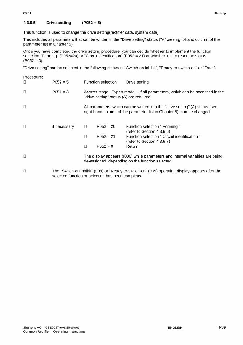
06.01 Start-Up
Siemens AG 6SE7087-6AK85-0AA0 ENGLISH 4-39Common Rectifier Operating Instructions
4.3.9.5 Drive setting (P052 = 5)
This function is used to change the drive setting(rectifier data, system data).
This includes all parameters that can be written in the "Drive setting" status ("A" ,see right-hand column of theparameter list in Chapter 5).
Once you have completed the drive setting procedure, you can decide whether to implement the functionselection "Forming" (P052=20) or "Circuit identification" (P052 = 21) or whether just to reset the status(P052 = 0).
"Drive setting" can be selected in the following statuses: "Switch-on inhibit", "Ready-to-switch-on" or "Fault".
Procedure:⇓ P052 = 5 Function selection Drive setting
⇓ P051 = 3 Access stage Expert mode - (if all parameters, which can be accessed in the"drive setting" status (A) are required)
⇓ All parameters, which can be written into the "drive setting" (A) status (seeright-hand column of the parameter list in Chapter 5), can be changed.
⇓ if necessary ⇓ P052 = 20 Function selection " Forming "(refer to Section 4.3.9.6)
⇓ P052 = 21 Function selection " Circuit identification "(refer to Section 4.3.9.7)
⇓ P052 = 0 Return
⇓ The display appears (r000) while parameters and internal variables are beingde-assigned, depending on the function selected.
⇓ The "Switch-on inhibit" (008) or "Ready-to-switch-on" (009) operating display appears after theselected function or selection has been completed

Start-Up 06.01
4-40 ENGLISH Siemens AG 6SE7087-6AK85-0AA0Common Rectifier Operating Instructions
4.3.9.6 Form DC link (P052 = 20)
DANGER
The "Form DC link" function may only be implemented if the commonrectifier and the converter(s) connected have the same voltage class(9th digit position of the MLFB).
If the converters have been left to stand idle for more than a year, the DC link capacitors must be re-formed. Ifthe converters are taken into service within a year of being delivered (factory number, rating plate); it is notnecessary to re-form the DC link capacitors. For more details on this subject, please refer to Section 4.3.12 ofthe converter's operating instructions
The DC link capacitors are formed as described below.
The "Form DC link" function can be selected in the "Ready to switch on" status (009).
Procedure:⇓ P408 Set the forming time (1.0 to 600.0 minutes; see Section 4.3.12 of the
converter's operating instructions
⇓ P052 = 20 Select the "Form DC link" function"
⇓ P key The operating display appears:The common rectifier must be switched on within 20 s, otherwise messageF091 (fault value 4) appears.
⇓ Switch on the rectifier/regenerating unit
NOTE
The firing pulses are enabled, the common rectifier carries current and the DC link is charged!
During the forming procedure, the connected SIMOVERT Master Drives FC, VC, SC must not be switched on.
⇓ Forming of the DC link takes place (duration as set with P406):While the forming time P408 is running, the control angle is reduced linearly from 120 degreesto 30 degrees and the DC link capacitor is charged up to the peak value of rectifier supplyvoltage.If DC link voltage reduction is selected (control word 1 bit 11, P571), the forming procedure willbe completed on reaching a DC link voltage of P318 * rectifier network peak value.During the forming procedure, the current limit set at P160 is not effective.
⇓ When this function has been completed, the "Ready to switch on" display (009) appears.

06.01 Start-Up
Siemens AG 6SE7087-6AK85-0AA0 ENGLISH 4-41Common Rectifier Operating Instructions
4.3.9.7 Circuit identification (P052 = 21)
This function identifies the DC link and the supply and re-assigns certain control parameters.Specific closed-loop control parameters are re-assigned in connection with this function.
Only the parameters of the reserve data sets currently selected are modified (see "Data sets" in Section 4.1.2and "Selecting the data sets" in Section 4.4).
NOTE
Circuit identification (i.e. automatic setting of the appropriate parameters) must be carried out, otherwise errormessage F061 will be generated when the unit is switched on.
While circuit identification is being carried out, the constellation of supply, and reactor arrangement as well asthe capacitive load connected to the DC link terminals of the common rectifier must be identical to theconstellation for normal operation later. The main reason being that the Ud controller gain that is set dependson the measured intermediate circuit capacitance.
If more than one inverter of the series SIMOVERT Master Drives 6SE70 are to be operated with the commonrectifier, whereby the number of inverters connected to the DC link at any one time varies, it is recommendedthat reserve data set selection is implemented. Up to 4 different configurations can be formed for this purposethat are each assigned to a reserve data set. Circuit identification has to be carried out separately for each ofthese reserve data sets. During circuit identification, the appropriate configuration must exist for the selecteddata set.
Circuit identification must be carried out whenever the supply network changes and/or whenever the number ofconnected inverters changes.
The "Circuit identification" function can be aborted at any time with an OFF command. This triggers faultmessage F091 "Circuit identification aborted by external cause".
During circuit identification, which is carried out in a series of separate stages, code numbers appear on thePMU that indicate the current working stage.
If an error occurs during a stage, the circuit identification function is aborted. The exact cause of the abort isindicated in the fault value r949 assigned to the fault number memory r947 (for a non-reset fault in index i001and if reset in index i009).
You will find a detailed description of the fault messages, associated fault values and a description on thewarning messages in Chapter 7 "Faults and Warnings".

Start-Up 06.01
4-42 ENGLISH Siemens AG 6SE7087-6AK85-0AA0Common Rectifier Operating Instructions
Die Anwahl "Stromkreisidentifikation" kann im Zustand "Einschaltbereit" (009) erfolgen.
Ablauf:⇓ P052 = 21 Funktionsanwahl Stromkreisidentifikation
⇓ P-Taste Es erscheint die Betriebsanzeige:Die Einspeiseeinheit muss innerhalb von 20s eingeschaltet werden, sonsterfolgt die Störmeldung F091 (Störwert 4).
⇓ Einschalten der Einspeiseeinheit
NOTE
During circuit identification the trigger pulses are released, the power supply unit draws current and the linkcircuit is partially charged:
Initially the control angle is reduced starting from 120 degrees until the link circuit voltage reaches 12.5 % of1.35 * mains supply voltage, after which a single large current crest is generated by triggering a thyristor pair ata control angle of 92 degrees. The current crest generated has a current conduction angle of approx. 40degrees, the peak value depends on the inductance of the incoming feeder circuit.
During circuit identification the motoring plant current limit P160 is not effective. The sum of the rated currentsof the inverters connected to the power supply unit should be appreciably less than the rated current of thepower supply unit.
⇓ The operating display appears. Circuit identification takes about 10 s with a discharged DC linkcapacitor. The following parameters are set automatically:
P140 Circuit resistance of the rectifier bridgeP141 Circuit inductance of the rectifier bridgeP144 Capacitance of the DC linkP310 Proportional gain of current controllerP311 Integral-action time of current controllerP313 Proportional gain of DC link voltage controller
⇓ On completion of the function, "Ready to switch on" (009) appears in the display.
NOTE
If a fault message occurs during circuit identification, the cause of the fault must be eliminated and the functionrepeated (see Section 7.1).
Circuit identification for 12-pulse mode must be carried out in succession on the 12-pulse master and on the 12-pulse slave units (see Section 3.8.5).

06.01 Start-Up
Siemens AG 6SE7087-6AK85-0AA0 ENGLISH 4-43Common Rectifier Operating Instructions
4.3.9.8 Display modified parameters (P052 = 22)
This function is used to display all parameters (regardless of the access stage) that differ from the factory setting(i.e. plant-specific parameters). This function only works with operator control via the PMU but not with theOP1S.Adjustable parameters that have no factory setting (P070) or whose value depends on other parameters(P071,...) are regarded as "modified".Those parameters that are dependent on P077 (see Section 4.3.9.1 "Factory setting") whose values differ fromthe setting for P077=0 are also regarded as modified."Modified" parameters for "special access" are also displayed that are only accessible to specially trainedpersonnel using P799.
The "Display modified parameters" function can be selected in all operating statuses.
Procedure:⇓ P052 = 22 Select the "Display modified parameters" function
⇓ P key Only parameters that differ from the factory setting appear on the PMU (i.e.plant-specific parameters), irrespective of the access stage (P051). It is notpossible to modify the parameter value here.
⇓ P052 = 0 Select the Return function
⇓ P key
NOTE
Parameters r990 and r991 provide a list of modified parameters for the PMU and also for the OP1S.
4.3.10 Functions
4.3.10.1 WEA (automatic restart)
The Automatic Restart function can be used for the automatic acknowledgment of faults and automatic restart ofthe unit following a power failure (F003, F004, F005, F007, F009 or F010) without the operator having tointervene.
If there is no voltage on one of the terminals 1U/L1, 1V/L2, 1W/L3, X9.1, X9.2, or if their values are not within thetolerance range and the DC link voltage has dropped below the threshold P074 * 1.35 * P071, the commonrectifier responds as follows:
P366 = 0: WEA (automatic restart) is inhibited
No automatic restart; the relevant fault message (F003, F004, F005, F007, F009 or F010) isinitiated..
P366 = 1: Acknowledgment of power failure after system recovery
The common rectifier enters the operating status o008 (Switch-on inhibit) or o009 (when switchingon/off with the I/O keys of the PMU). On power recovery, a new ON command must be given toenable the DC link to re-charge. The converter is not automatically restarted by the WEA function.
Start-Up 06.01
4-44 ENGLISH Siemens AG 6SE7087-6AK85-0AA0Common Rectifier Operating Instructions
P366 = 2 Restart after system recovery and pre-charging of the DC link after system recovery
While the system is down, the automatic controllers and firing pulses of the rectifier bridge areinhibited. The common rectifier enters the status o010. On power recovery, the unit is automaticallyswitched on again by the WEA. The DC link is re-charged.The unit is only switched back on again if there is still an ON command (control word bit 0) activefollowing system recovery. The WEA function is therefore not possible with an ON command (controlword bit 0) programmed from the PMU or operator panel OP1S provided the external 24 V supplydoes not fail.
IMPORTANT: External measures must be taken to guarantee safety on an automatic restart!
Warning A065 (Automatic restart active):This warning bit is set following a system failure if the automatic restart function is active, and reset following arestart by the WEA and completion of the pre-charging process.The unit can also be switched off by a manual OFF command during this restart phase. Please also refer toChapter 7 "Faults and Warnings"
WARNING
In the event of system failures when the WEA function has been activated (P366 = 2), theunit may restart on system recovery and re-charge the DC link.
Consequently when the WEA function of the connected inverter has been activated(P366 = 2 or P366 = 3) the inverter can be switched on once more.
Fatal injuries, severe bodily harm or damage to property and machinery may result if thearea surrounding the drive is entered while the drive is in this state.
NOTE
If the kinetic buffering function (KIP) is activated on a connected converter from the series SIMOVERT MasterDrives 6SE70, on the common rectifier, P366=2 must be parameterized.
If two common rectifiers for 12-pulse mode are coupled via peer-to-peer protocol via the basic unit interfaceSST2, the peer-to-peer telegram failure time monitoring must be switched off via P687.i003=0 on the "12-pulsemaster" unit, otherwise the automatic switch-on with the parameterization P366=2 (on both units) will not workcorrectly if the electronics supply voltage fails.

06.01 Start-Up
Siemens AG 6SE7087-6AK85-0AA0 ENGLISH 4-45Common Rectifier Operating Instructions
4.3.10.2 Externally requested and current-dependent Ud reduction
Up to and including Unit Software Release 3.1, Ud reduction was implemented only upon external request bymeans of the control word 1 command "Ud reduction demanded" (STW1, Bit 11= 1):
When an edge is detected on this command (source selection by P571), the Ud setpoint is lowered to the value(1.35*Umains,infeed*P318/100.00%) according to P318 (with or without deceleration ramp according to P330,depending on whether P330 has an odd or even value) and regenerative feedback is disabled (the message"Recovery not ready“ is displayed, status word ZSW1, Bit 10= 0). The DC link should now discharge (freedischarge or current withdrawal from the DC link). When the DC link voltage has been reduced, the message"Ud is reduced" is issued via ZSW1, Bit 13= 1. Energy recovery is re-released again, the message ZSW1, Bit10= 1 is issued. When the message "Ud is reduced" has been issued, an inverter connected to the DC link maystart returning energy into the DC link.
An external logical linking is required for the energy recovery!
As from Unit Software Release 3.2, the Ud can also be reduced automatically, as an alternative, depending onthe DC link current Id:
When the current-dependent Ud reduction is released by P323= 1, the command for the reduction is generatedinternally by Ud. The Ud setpoint is automatically reduced to the value in accordance with P318 when Id(averaged over 3 current crests) falls below the threshold P321. If Id exceeds the sum of threshold P321 andhysteresis P322, the "full" Ud setpoint value (1.35*Uline,feed) is selected again. In contrast to Ud lowering bymeans of STW1, bit 11, precharge time P329 or discharge time P330 are always active (setpoint input withramp) when the Ud setpoint is specified internally.
Attention: Undisturbed recovery mode is only possible if, after falling below P321, the load current withdrawn(by the inverters connected to the DC link) still remains positive for a sufficient length of time beforechanging direction to permit a reduction of the DC link voltage to the specified value before recoveryis started. The current-dependent Ud reduction functions therefore only if an appropriate load cycleexists !

Start-Up 06.01
4-46 ENGLISH Siemens AG 6SE7087-6AK85-0AA0Common Rectifier Operating Instructions
4.4 Function diagrams
Notes on the function diagrams:
The function diagrams on the two following sheets show the controller structure of the common rectifier unit.
A value in brackets for a parameter indicates the factory setting of the parameter in question.
Switch positions drawn are the factory setting.
These function diagrams also contain parameters that are not listed in the parameter list (Chapter 5) of theseoperating instructions. They are the expert parameters that are only visible at the PMU if P051 = 3 and P799 = 4.These expert parameters contain a useful factory setting and must not usually be altered.
Not only the parameter but also the most important "connectors" (Kxxx) are drawn into the function diagrams.Connectors can be seen as "digital measuring points" of internal controlled variables or memory locations (e.g.DC link voltage K287, DC link current K114, control angle K100). The connectors are only used for factoryinternal diagnostic purposes and are not described in more detail in these operating instructions. A hexadecimaldisplay of a single connector value is possible using the expert parameters P787 and r786 on the PMU byparameterizing the number of the connector to be displayed at parameter r786 at P787.

06.01 Start-Up
Siemens AG 6SE7087-6AK85-0AA0 ENGLISH 4-47Common Rectifier Operating Instructions
P31
3P
314
P32
0 (
5m
s)
P07
4 (
61%
)
1,35
*P
071
01
P32
1 (
30,0
0%)
P32
2 (
20,0
0%)
K30
2
106
,8%
10
100%
0%
10
<>
9999P
320
(5)
9999
10
100%
P31
8 (8
0,00
%)
K17
9
6005
6004
6003
00%
1 0
Id -
C
∆t∆ Ud
CP
144
K17
8K
173
K10
9
r035
P33
0 (2
000
ms)
P32
9 (5
00m
s)
*3)
P31
6 (
0,0
1%
)
P31
7 (-
1,0
0%
)K
163
1,3
5
K28
7K
167
K16
5
r037
+
-
K34
6
K19
0
r036
r038
K17
5
K16
0
P78
7 (0
)
K
r786
&1 ≥
P32
3 (0
)
Id
P32
1P
322
1,35
*P
071
K10
9Id
K30
1
K30
3
K10
5
K38
8
K36
0
K32
6
K31
5
K30
0
K30
4
K29
2
K11
4
Ud
Ud
r006
P79
7(0
011)
K17
1
(0010
)P
315
r030
K21
3
K19
4
K16
8
(001
0)P
315
P48
8 (0
)
Ud Id
87
56
43
21
Filt
eri
ng
Tim
e c
ons
t.. = 1
s
Ave
rag
e o
f th
ree
Kp
corr
ectio
n *
1)
Filt
eri
ng
min
max
Id-d
ependent
Ud
red
uct
ion S
ST
2 pe
er-t
o-pe
er, w
ord5
SS
T2
peer
-to-
peer
, w
ord4
SS
T2
peer
-to-
peer
, w
ord3
Id a
dditi
onal
se
tpoin
t se
lect
ion
P48
8 (0
)
Ave
rag
e o
f th
ree
Ud
co
ntr
ol,
Id s
etp
oin
t g
en
era
tion
Con
nect
or s
ele
ctio
n di
spla
y (H
EX
)
U_ne
tw_in
feed
(n
etw
ork
volta
ge
at
infe
ed p
ow
er
sect
ion)
(Firin
g cy
cle
mean
val
ue)
(3rd
sam
plin
g v
alu
e)
(Cu
rren
t m
axi
mum
v
alu
e m
ean)
*1)
on u
nbal.
para
llel s
witc
hin
g acc
. to
P
076 a
nd / o
r 12-p
uls
e ope
ratio
n
*3)
ram
p-up
/ram
p-do
wn
time
: =
0 o
nre
ques
t by
ST
W.b
it11
cont
rolle
d U
d_se
t_de
cele
ratio
n lo
gic
if no
AU
S1
pen
ding
)
*2)
K1
90: =
Set
K1
67 (
Ud
actu
al v
alu
e):
on
neg. edge o
v "U
d_se
t re
duct
ion",
on
"no o
pe
ratio
n"
on
AU
S1
and
"not
rea
dy for
reg
ener
ativ
e fe
edba
ck",
in
12-
puls
e op
erat
ion
on w
aitin
g in
sta
tus
"- -
"
Load c
urre
nt
inje
ctio
n
C c
orre
ctio
n *
1)
Rou
ndin
g 60
ms
Ram
p-fu
nctio
n-ge
nera
tor
corr
ectio
n *
2)
exte
rnal
ly vi
a S
TW
1, bi
t11
(sou
rce
sele
ctio
n w
ith P
571)
Com
mand
for
Ud_
set_
reduct
ion:
Add
ition
al im
port
ant co
nnec
tors
:
ST
W1
(co
ntro
l wor
d)
ZS
W1
(st
atus
wor
d)
Ope
ratin
g st
atus
Firin
g cy
cle
dura
tion
Thy
rist
or p
air
code
Devi
atio
n o
f pass
age
thro
ugh z
ero
Reg
ener
ativ
e fe
edba
ck n
etw
ork
volta
ge U
-V
Reg
ener
ativ
e fe
edba
ck n
etw
ork
volta
ge V
-W
Reg
ener
ativ
e -f
eedb
ack
netw
ork
volta
ge
W-U
(Last
sam
plin
g v
alue
)
Dis
char
gin
g tim
e
Pre
char
gin
g tim
eD
ead
band
pos
. th
resh
old
De
adba
ndn
eg
. th
resh
old
Ud_
set-
reduct
ion
Thr
esho
ld
Hys
tere
sis
P c
om
pone
nt (a
ctiv
e)I co
mpo
nent
(=
0)
Effe
ctiv
e K
p
to S
heet
2
Ud c
ontr
olle
r
Kp
Tn
She
et 1
Figure 4.4.1 Ud control, Id setpoint generation

Start-Up 06.01
4-48 ENGLISH Siemens AG 6SE7087-6AK85-0AA0Common Rectifier Operating Instructions
1 0
=M
I 1
MI 2
MI 3
MI 4
MI 5
MI 6
MII
1M
II 2
MII
3M
II 4
MII
5M
II 6
(001
1)P
797
Id, s
oll
*1)
*1)
6005
6004
6003
00%
P48
6 (0
)
K12
0
K11
9
K11
3
K11
0
K14
7
K13
1
K11
8
K13
2
r034
+
-
K10
0
r033
P31
5(0
010)
P14
1P
140
P14
2P
143
K11
6K
115
K11
7
K12
1
P16
0 (
150
,0%
)
P16
1 (
-150
,0%
)
P79
7(0
011)
K29
2
P77
5 (0
°)
0.05
%
I 0 II P77
3
P77
4
(211
1)P
312
K31
0
K30
5
P77
4(-
3,00
%)
P77
3(0
,01%
)
P07
4(6
1%
)P
076
(002
)
P31
0(0
,15)
P31
1(0
,015
s)
P7
771
65°
P7
76
K11
6
P78
5 (1
)
P77
6(1
50°)
P77
7(2
0,00
%)
K10
2
P31
2(2
111)
87
56
43
21
She
et 2
P77
8, P
779,
Id,
Ud,
U_n
etw
(filt
erin
g/a
vera
gin
gan
d ph
ase
cor
rect
ion
of n
etw
ork
pass
ages
thro
ugh
zero
)
SS
T2 p
eer-
to-p
eer,
word
5
SS
T2 p
eer-
to-p
eer,
word
4
SS
T2 p
eer-
to-p
eer,
word
3
Id c
ontr
ol,
firin
g pu
lse
Ud_
setp
oint
U n
etw
> P
074
Cont
rol w
ord
, bi
t27
(sou
rce s
elec
tion
with
P587)
Act
ual v
alue
ave
rage
(ave
rage v
alue w
ith
6 sa
mpl
ing v
alu
es
of the
cur
rent
firin
g cy
cle)
*1)
0... cu
rrent v
alue
1
...
ave
rage o
f th
ree
2
...
inte
rmitt
ent: a
vera
ge o
f thr
ee
co
ntin
uous:
act
ual v
alu
e
*2)
K1
19:=
0 a
t de
tect
ed c
omm
utat
ion
failu
re,
on r
etur
n (if K
120 >
0)
n
etw
ork
vol
tage failu
re (if
K12
0 <
0)
K
119:=
-0,
006%
, if
all
conditi
ons
are
fu
lfille
d that
pre
vent re
g. fe
ed
back
on
P7
97=
xx1x
Ud//Id
cont
rol
switc
hove
r(M
est
er-
/Sla
ve-
oper
atio
n)
P31
2 (2
111)
P c
om
pone
nt (a
ctiv
e)I co
mpo
nent
(a
ctiv
e)
U_n
etw
_inf
eed
U_n
etw
_reg
ener
ativ
e_fe
edba
ck
alph
a-G
alph
a-W
Dis
able
regen
era
tive
feedback
on
:S
TW
1.B
it12
= 0
(n
o r
ege
n._f
eedb
ack
ena
ble)
,U
d >
0,9
375
*1,3
5*
U_n
etw
_re
gen._
feedba
ck o
rU
d >
0,8
75*
1,35
*U
_ne
tw_r
egen
._fe
edb.
at A
US
1,U
d >
1,3
5*U
_net
w_r
egen
._fe
edb
ack*
P31
8/10
0%(if the
Ud
_set
red
uctio
n lo
gic
dem
ands
it),
U_n
etw
_reg
en._
feed
back
< P
074
,pre
charg
ing (
ram
p_fu
nct
ion r
am
p a
cc. P
329),
P07
6=xx
1 (
mo
torize
d op
erat
ion
only
)
Low
est neg
.cu
rrent
lim
it
Tem
pera
ture
mod
el,
limita
tion to
±150%
, +
136
%/-
125
%or
+100
%/-
92%
Thy
rist
orte
mpe
ratu
re r
ise
ST
W1
, bit
12(s
ourc
ese
lect
ion
with
P572)
Ud
(las
t sa
mp
ling
valu
e)
U_n
ew_r
egen
erat
ive_
fee
dbac
k
Sto
p I co
mp
onen
t
I-A
nt. =
0
Infe
ed
/ re
gen
era
tive
feedback
/ n
o su
ppl
y direc
tion
alph
a-W
-shi
ft
Id a
t in
term
itte
nt li
mit
Cur
rent
lim
itin
infe
ed d
irect
ion
curr
rent lim
it in
regene
rativ
efe
edba
ck d
irec
tion
Con
trol
word
I2t
Id_s
et
Set
poin
t av
erag
e
Long /
short
puls
es
Add
ition
alal
pha-
W-p
ulse
Sel
ect
ion
Id
setp
oin
t f
or
Id c
ontr
ol
Log
ic f
orpr
eve
ntin
g in
fee
dor
reg
en
era
tive
feed
back
*2)
Low
est po
s.cu
rrent
lim
it
Fe
edfo
rwar
d c
ontr
ol
Id c
ontr
olle
r
U_c
ontr
Ud Id
fro
m S
hee
t 1
R_i
n
R_r
egen
L_re
gen
Kp
Tn
Id a
t int
erm
ittent
limit
0 b
zw.
-0,0
06%
|Id
|
Id
L_in
Id
Co
ntro
l se
t
Id
Ud
Figure 4.4.2 Id control, firing pulse

06.01 Start-Up
Siemens AG 6SE7087-6AK85-0AA0 ENGLISH 4-49Common Rectifier Operating Instructions
87
56
43
21
20
ms
#
U
+10
V
-10
V
... 3 2 1 0
P6
57C
U-A
A o
ffse
t
DA
CH
ard
war
e fi
lteri
ng
to te
rmin
al b
lock
P6
55C
U-A
A a
ctua
l va
lue
sP
656
CU
-AA
gai
n
...
...
...
Co
nten
ts o
f par
ame
ter
001 0
An
alo
g o
utp
ut
CU
R
UO
FF =
Pa
ram
ete
r va
lue
[%
]10
0%x
(Gai
n [
V]
+ O
ffs
et [
V])
Figure 4.4.3 Analog output CUR
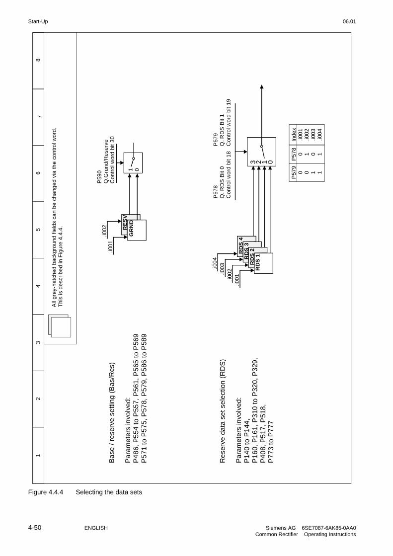
Start-Up 06.01
4-50 ENGLISH Siemens AG 6SE7087-6AK85-0AA0Common Rectifier Operating Instructions
RE
SV
1 0
.i00
1.i0
02
87
56
43
21
RD
S 2
.i00
1
RD
S 3
RD
S 4
.i00
3.i0
04
.i00
2 RD
S 1
3 2 1 0
P59
0Q
.Gru
nd
/Re
serv
eC
ontr
ol w
ord
bit
30
Ba
se /
rese
rve
se
ttin
g (B
as/R
es)
Pa
ram
ete
rs in
volv
ed:
P4
86,
P5
54 to
P55
7, P
561,
P5
65 t
o P
569
P5
71
to P
575
, P57
8, P
579,
P5
86 t
o P
589
P57
8Q
. RD
S B
it 0
Con
trol
wor
d b
it 1
8R
ese
rve
da
ta s
et s
ele
ctio
n (
RD
S)
Pa
ram
ete
rs in
volv
ed:
P1
40
to P
144
,P
16
0, P
161
, P3
10 to
P32
0, P
329
, P
40
8, P
517
, P5
18,
P7
73
to P
777
P57
9Q
. RD
S B
it 1
Con
trol
wor
d b
it 1
9
P57
90 0 1 1
P57
80 1 0 1
Ind
ex
.i00
1.i0
02
.i00
3.i0
04
All
gre
y-h
atch
ed b
ackg
rou
nd f
ield
s ca
n b
e c
ha
nge
d v
ia th
e c
on
tro
l wo
rd.
Thi
s is
de
scri
bed
in F
igu
re 4
.4.4
.
GR
ND
Figure 4.4.4 Selecting the data sets

06.01 Start-Up
Siemens AG 6SE7087-6AK85-0AA0 ENGLISH 4-51Common Rectifier Operating Instructions
4.5 Starting up optional supplementary boards
For installation of the board, see Section 9.1, Options for integration into the electronics box. The unit onlysupports 1 optional board of each type.
All communication-related settings must be made using parameters.
The supplementary boards must then be logged in the unit via P090 or P091. Otherwise they will be ignored bythe unit and no communication will take place.
4.5.1 Procedure for starting up technology boards(T100, T300, T400):
NOTE
Freely configurable technology boards T300 and T400 are guaranteed to operate correctly (board runup anddata exchange with the SIMOVERT 6SE70). The user, however, must bear responsibility for ensuring that thesystem is properly configured.
1 Disconnect the power supply and insert the board in location 2.
2 After the next switch-on, the board must be logged in via P090. The parameters of the technology board(d and H parameters, in some cases also c and L parameters) can then be accessed.
The connections for the process data on the basic unit are made using the corresponding source andtarget connections (see Section 4.3).For the meaning of the bits in the control words and the status words, see Section 4.3.
If a communication board is used in addition to a technology board, then data are exchanged with thebasic converter via the technology board. The basic converter cannot directly access the data of thecommunication board. The connections for the process data to be transferred are then determined by theconfiguration or parameter settings of the technology board.
If a technology board is mounted in location 2, then only one communication board (CBC, CBD, CBP2,SCB1, SCB2) may be installed in slot G. Other boards are not supported

Start-Up 06.01
4-52 ENGLISH Siemens AG 6SE7087-6AK85-0AA0Common Rectifier Operating Instructions
4.5.2 Sequence of operations for starting up PROFIBUS boards(CBP2):
1 Switch off the power supply and insert the board or adapter with board. For installation details see Section9.1, Options for integration into the electronics box.
2 The following are important communication parameters:
- P697 PPO type, definition of the number of words in the parameter and process data section of thetelegram (required only if the PPO type cannot be set via PROFIBUS-DP master)
- P695 Telegram failure time for process data (0 = deactivated)The DP master configuring data determine whether the slave (CBP2) must monitor telegramtraffic with the master. If this monitoring function is activated, the DP master passes a time value(watchdog time) to the slave when the link is set up. If no data are exchanged within this period,the slave terminates the process data exchange with the SIMOVERT 6SE70. The latter canmonitor the process data as a function of P695 and activate fault message F082
- P918 Busadresse
- P053 Parameterization enable (same function as P927; need only be set if parameters are to beassigned via PROFIBUS)
- P090 or P091 for logging the board
The connections for the process data on the communications board are made using the correspondingsource and target parameters (see Section 4.3). For the meaning of the bits in the control words and thestatus words, see Section 4.3.
3 Switching off and on of the electronics supply voltage. Doing this causes the values of parameters P695,P697 and P918 to be transferred from the supplementary board.
The CBP2 (Communication Board PROFIBUS) serves to link drives and higher-level automation systems via thePROFIBUS-DP. For the purpose of PROFIBUS, it is necessary to distinguish between master and slaveconverters.
Masters control the data traffic via the bus and are also referred to as active nodes. There are twoclasses of master:DP masters of class 1 (DPM1) are central stations (e.g. SIMATIC S5, SIMATIC S7 or SIMADYN D)which exchange data with slaves in predefined message cycles.DPM1s support both a cyclic channel (transmission of process data and parameter data) and an acyclicchannel (transmission of parameter data and diagnostic data).DP masters of class 2 (DPM2) are programming, configuring or operator control/visualization devices(e.g. SIMOVIS) which are used in operation to configure, start up or monitor the installation.DPM2s support only an acyclic channel for transferring parameter data.
The contents of the data frames transferred via these channels are identical to the structure of theparameter section (PKW) as defined by the USS specification.

06.01 Start-Up
Siemens AG 6SE7087-6AK85-0AA0 ENGLISH 4-53Common Rectifier Operating Instructions
The following diagram shows the services and channels supported by a CBP2:
CPU SIMOVIS
MSCY_C1 MSAC_C2 MSAC_C2
PPO DS 0 DS 100
(Class 1 master) (Class 2 master)
Cyclic channel Acyclic channel Acyclic channel
PKWJob/response
PZDSetpoint/actual values
Diagnosis PKWJob/response
PKWJob/response
PZDSetpoint/actual values
Parameter channel Process data channel
Slaves (e.g. CBP, CB1) may only respond to received messages and are referred to as passive nodes.
PROFIBUS (Process Field Bus) combines high baud rates (to RS485 standard) with simple, low-costinstallation. The PROFIBUS baud rate can be selected within a range of 9.6 kbaud to 12 Mbaud and is set for alldevices connected to the bus when the bus system is started up.The bus is accessed according to the token-passing method, i.e. permission to transmit for a defined timewindow is granted to the active stations (masters) in a "logical ring". The master can communicate with othermasters, or with slaves in a subordinate master-slave process, within this time window.PROFIBUS-DP (Distributed Peripherals) predominantly utilizes the master-slave method and data is exchangedcyclically with the drives in most cases.
The user data structure for the cyclic channel MSCY_C1 (see picture above) is referred to as a ParameterProcess(data) Object (PPO) in the PROFIBUS profile for variable-speed drives. This channel is also frequentlyreferred to as the STANDARD channel.The user data structure is divided into two different sections which can be transferred in each telegram:
PZD sectionThe process data (PZD) section contains control words, setpoints, status words and actual values.
PKW sectionThe parameter section (PKW - Parameter ID Value) is used to read and write parameter values.
When the bus system is started up, the type of PPO used by the PROFIBUS master to address the drive isselected. The type of PPO selected depends on what functions the drive has to perform in the automationnetwork.
Process data are always transferred and processed as priority data in the drive.Process data are "wired up" by means of connectors of the basic unit (drive) or via technology boardparameters, if these are configured.
Parameter data allow all parameters of the drive to be accessed, allowing parameter values, diagnosticquantities, fault messages, etc. to be called by a higher-level system without impairing the performance of thePZD transmission.

Start-Up 06.01
4-54 ENGLISH Siemens AG 6SE7087-6AK85-0AA0Common Rectifier Operating Instructions
A total of five PPO types are defined:
PKW section PZD section
PKE IND PWE PZD1STW
1ZSW
1
PZD2HSWHIW
PZD3 PZD4 PZD5 PZD6 PZD7 PZD8 PZD9 PZD10
1st
word2nd
word3rd
word4th
word1st
word2nd
word3rd
word4th
word5th
word6th
word7th
word8th
word9th
word10th
word
PPO1
PPO2
PPO3
PPO4
PPO5
PKW: Parameter ID value IND: Index ZSW Status word
PZD: Process data PWE: Parameter value HSW: Main setpoint
PKE: Parameter identifier STW: Control word ISW: Main actual value
The acyclic channel MSCY_C2 (see diagram above) is used exclusively for the start-up and servicing ofSIMOVIS.
4.5.2.1 Mechanisms for processing parameters via the PROFIBUS:
The PKW mechanism (with PPO types 1, 2 and 5 and for the two acyclic channels MSAC_C1 and MSAC_C2)can be used to read and write parameters. A parameter request job is sent to the drive for this purpose. Whenthe job has been executed, the drive sends back a response. Until it receives this response, the master must notissue any new requests, i.e. any job with different contents, but must repeat the old job.
The parameter section in the telegram always contains at least 4 words:
PKE IND
Parameter identifier Index Parameter value 1
PWE1 (H word)
Paramter value 2
PWE2 (L word)
Details about the telegram structure can be found in Section 4.5.6, "Structure of request/response telegrams“.
The parameter identifier PKE contains the number of the relevant parameter and an identifier whichdetermines the action to be taken (e.g. "read value").
The index IND contains the number of the relevant index value (equals 0 in the case of nonindexedparameters). The IND structure differs depending on the communication mode:
- Definition in the PPOs (structure of IND with cyclical communication via PPOs)
- Definition for acyclical channels MSAC_C1 and MSAC_C2 (structure of IND with acyclical communication)
The array subindex (referred to simply as "subindex" in the PROFIBUS profile) is an 8-bit value which istransferred in the high-order byte (bits 8 to 15) of the index (IND) when data are transferred cyclically viaPPOs. The low-order byte (bits 0 to 7) is not defined in the DVA profile. The low-order byte of the index word isused in the PPO of CBP2 to select the correct number range (bit7 = Page Select bit) in the case of parameternumbers of > 1999).
In the case of acyclical data traffic (MSAC_C1, MSAC_C2) the number of the index is transferred in the low-order byte (bits 0 to 7). Bit 15 in the high-order byte is used as the Page Select bit. This assignment complieswith the USS specification.
Index value 255 (request applies to all index values) is meaningful only for acyclical transmission via MSAC_C1.The maximum data block length is 206 bytes with this transmission mode.

06.01 Start-Up
Siemens AG 6SE7087-6AK85-0AA0 ENGLISH 4-55Common Rectifier Operating Instructions
The parameter value PWE is always transferred as double word (32-bit value) PWE1 and PWE2. The high-order word is entered as PWE1 and the low-order word as PWE2. In the case of 16-bit values, PWE1 must beset to 0 by the master.
Example
Read parameter P140.004 (for details, see Section 4.5.6, "Structure of request/response telegrams“):
Request identifier PKE = 0x608C (request parameter value (array) P101),Index IND = 0004h = 4dParameter value PWE1 = PWE2 = 0
SIMOVERT response:
Response identifier PKE = 0x408C,Index IND = 0004h = 4dValue of P140.004 = 1388h = 5000d, i.e. 5.000Ω (PWE1 = 0, because it is not a double word parameter)
Rules for job/response processing:
A job or a response can only ever refer to one parameter.
The master must send the job repeatedly until it receives an appropriate response from the slave. Themaster recognizes the response to the job it has sent by analysing the response identifier, the parameternumber, the parameter index and the parameter value.
The complete job must be sent in one telegram. The same applies to the response.
The actual values in repeats of response telegrams are always up-to-date values.
If no information needs to be fetched via the PKW interface (but only PZD) in cyclic operation, then a "Nojob" job must be issued.
PROFIBUS devices have a variety of difference performance features. In order to ensure that all mastersystems can correctly address each supplementary board, the characteristic features of each board are stored ina separate device master file (GSD).You need file <siem8045.gsd> for CBP2.The appropriate file can be chosen in the selection menu for the SIMOVERT MASTER DRIVES files in laterversions of the configuring tool.If a device master file is not available in the menu, it can be collected from an Internet site. The Internet addressis http://www.ad.siemens.de/support/html_76/index.shtml.Product Support/PROFIBUS GSD files/Drives/ . Have all entries displayed using the search function and click onthe search results.
SIMOVERT/SIMOREG/SIMADYN CBPFile: siem8045.gsd
The communication boards can only be operated on a non-Siemens master as a DP standard slave, thecorresponding GSD file containing all necessary information for this mode.
Detailed information about communication via PROFIBUS can be found in Section 8.2 of the compendium forSIMOVERT MASTER DRIVES Motion Control (order no. 6SE7080-0QX50).
4.5.2.2 Diagnostic tools:
LED displays of CBP2 (flashing LEDs mean normal operation):
Red LED Status of CBP2Yellow LED Communication between SIMOVERT and CBP2Green LED Communication between CBP2 and PROFIBUS
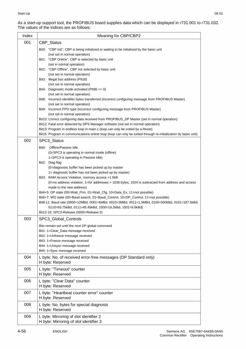
Start-Up 06.01
4-56 ENGLISH Siemens AG 6SE7087-6AK85-0AA0Common Rectifier Operating Instructions
As a start-up support tool, the PROFIBUS board supplies data which can be displayed in r731.001 to r731.032.The values of the indices are as follows:
Index Meaning for CBP/CBP2
001 CBP_Status
Bit0: "CBP Init", CBP is being initialized or waiting to be initialized by the basic unit
(not set in normal operation)
Bit1: "CBP Online", CBP is selected by basic unit
(set in normal operation)
Bit2: "CBP Offline", CBP not selected by basic unit
(not set in normal operation)
Bit3: Illegal bus address (P918)
(not set in normal operation)
Bit4: Diagnostic mode activated (P696 <> 0)
(not set in normal operation)
Bit8: Incorrect identifier bytes transferred (incorrect configuring message from PROFIBUS Master)
(not set in normal operation)
Bit9: Incorrect PPO type (incorrect configuring message from PROFIBUS Master)
(not set in normal operation)
Bit10: Correct configuring data received from PROFIBUS_DP Master (set in normal operation)
Bit12: Fatal error detected by DPS Manager software (not set in normal operation)
Bit13: Program in endless loop in main.c (loop can only be exited by a Reset)
Bit15: Program in communications online loop (loop can only be exited through re-initialization by basic unit)
002 SPC3_Status
Bit0: Offline/Passive Idle
(0=SPC3 is operating in normal mode (offline)
1=SPC3 is operating in Passive Idle)
Bit2: Diag flag
(0=diagnostic buffer has been picked up by master
1= diagnostic buffer has not been picked up by master)
Bit3: RAM Access Violation, memory access >1.5kB
(0=no address violation, 1=for addresses > 1536 bytes, 1024 is subtracted from address and access
made to the new address)
Bit4+5: DP state (00=Wait_Prm, 01=Wait_Cfg, 10=Data_Ex, 11=not possible)
Bit6+7: WD state (00=Baud search, 01=Baud_Control, 10=DP_Control, 11=not possible)
Bit8-11: Baud rate (0000=12MBd, 0001=6MBd, 0010=3MBd, 0011=1,5MBd, 0100=500kBd, 0101=187.5kBd,
0110=93.75kBd, 0111=45.45kBd, 1000=19.2kBd, 1001=9.6kBd)
Bit12-15: SPC3-Release (0000=Release 0)
003 SPC3_Global_Controls
Bits remain set until the next DP global command
Bit1: 1=Clear_Data message received
Bit2: 1=Unfreeze message received
Bit3: 1=Freeze message received
Bit4: 1=Unsync message received
Bit5: 1=Sync message received
004 L byte: No. of received error-free messages (DP Standard only)H byte: Reserved
005 L byte: "Timeout" counterH byte: Reserved
006 L byte: "Clear Data" counterH byte: Reserved
007 L byte: "Heartbeat counter error" counterH byte: Reserved
008 L byte: No. bytes for special diagnosisH byte: Reserved
009 L byte: Mirroring of slot identifier 2H byte: Mirroring of slot identifier 3

06.01 Start-Up
Siemens AG 6SE7087-6AK85-0AA0 ENGLISH 4-57Common Rectifier Operating Instructions
Index Meaning for CBP/CBP2
010 L byte: Mirroring of P918 (CB bus addr.)H byte: Reserved
011 L byte: "Re-config. by CUD" counterH byte: "Initialization runs" counter
012 L byte: Error ID DPS manager errorH byte: Reserved
013 L byte: PPO type foundH byte: Reserved
014 L byte: Mirroring of "DWord specifier ref"
015 H byte: Mirroring of "DWord specifier act"
016 L byte: DPV1:DS_Write, pos. ack. counterH byte: Reserved
017 L byte: DPV1:DS_Write, neg. ack. counterH byte: Reserved
018 L byte: DPV1:DS_Read, pos. ack. counterH byte: Reserved
019 L byte: DPV1:DS_Read, neg. ack. counterH byte: Reserved
020 L byte: DP/T:GET DB99 pos. ack. counterH byte: DP/T:PUT DB99 pos. ack. counter
021 L byte: DP/T:GET DB100 ps. ack. counterH byte: DP/T:PUT DB100 ps. ack. counter
022 L byte: DP/T:GET DB101 ps. ack. counterH byte: DP/T:PUT DB101 ps. ack. counter
023 L byte: DP/T service neg. acknow. counterH byte: DP/T:Application association pos. acknow. counter
024 Reserved
025 Date of creation: Day, month
026 Date of creation: Year
027 Software version (Vx.yz, display x)
028 Software version (Vx.yz, display yz)
029 Software version: Flash-EPROM checks.
030 Reserved
031 Reserved
032 Reserved
Fault and alarm messages:
For details about fault messages, see Section 7.
Fault F080An error occurred as board CBP2 was being initialized, e.g. incorrect value of a CB parameter, incorrectbus address or defective module.
Fault F081The heartbeat counter (counter on CBP2) which is monitored by SIMOVERT 6SE70 for "signs of life" fromthe board has not changed for at least 800 ms.
Fault F082Failure of PZD telegrams or a fault in the transmission channel.

Start-Up 06.01
4-58 ENGLISH Siemens AG 6SE7087-6AK85-0AA0Common Rectifier Operating Instructions
Alarm A081The identifier byte combinations transmitted by the DP master in the configuration telegram do not matchthe permitted identifier byte combinations (configuring error on DP master)Effect: No link can be established with the DP master, reconfiguration necessary.
Alarm A082No valid PPO type can be determined from the configuration telegram from the DP master.Effect: No link can be established with the DP master, reconfiguration necessary.
Alarm A083No user data, or only invalid data, are being received from the DP master.Effect: The process data are not transferred to the basic unit. When the telegram failure monitoringfunction is active (P695 set to value other than 0), this disturbance generates fault message F082 withfault value 10.
Alarm A084The exchange of data between the communication board and DP master has been interrupted (e.g. cablebreak, bus connector removed or DP master switched off).Effect: When the telegram failure monitoring function is active (P695 set to value other than 0), thisdisturbance generates fault message F082 with fault value 10
Alarm A085Error in the DPS software of the communication board.Effect: Fault message F081 is generated.
Alarm A086Failure of heartbeat counter detected by SIMOVERT 6SE70.Effect: Interruption in communication with PROFIBUS.
Alarm A087DP slave software has detected serious fault, fault number in diagnostic parameter n731.08.Effect: Total communication failure (secondary fault F082).
Alarm A088At least 1 configurable internode transmitter is not yet active or has failed again (for details, see diagnosticparameter n731).Effect:If a transmitter is not yet active, the associated setpoints are set to "0" as an alternative. If aninternode transmitter fails again, transmission of the setpoints to the SIMOVERT 6SE70 may beinterrupted depending on the setting of P700 (with secondary fault F082).

06.01 Start-Up
Siemens AG 6SE7087-6AK85-0AA0 ENGLISH 4-59Common Rectifier Operating Instructions
4.5.3 Sequence of operations for starting up CAN bus boards (CBC):
1 With the power supply switched off, insert the board with adapter board (ADB) into the slot. For installationdetails see Section 9.1, Options for integration into the electronics box.
2 The following are important communication parameters:
P696 Basic identifier for PKW request/PKW response
P697 Basic identifier for PZD receive
P698 Basic identifier for PZD transmit
P699 No. of the PZD for PZD transmit
P700 Refreshment rate for PZD transmit
P701 Basic identifier for PZD receive broadcast
P702 Basic identifier for PZD receive multicast
P703 Basic identifier for PZD receive lateral communication
P704 Basic identifier for PKW request broadcast
P705 Baud rate, when P706.002 = 0:0=10kBit/s, 1=20kBit/s, 2=50kBit/s, 3=100kBit/s, 4=125kBit/s, 5=250kBit/s, 6=500kBit/s,7=reserved, 8=1MBit/s
P706.01 0 = functionality corresponding to layer 2 of the ISO OSI 7-layer model (CANopen is notsupported by the SIMOVERT 6SE70 rectifier/regenerative feedback unit
P706.02 Bus timing (this should not be changed)
P695 Telegram failure time (0 = deactivated)
P918 Bus address (node ID)
P053, P927 Parameterization enable (need only be set if parameter values are to be altered via theCAN bus)
P090 or P091 Logging the board
The connections for the process data on the communications board are made using the correspondingsource and target parameters (see Section 4.3). For the meaning of bits in the control words and thestatus words, see Section 4.3.
3 Switching off and on of the electronics supply voltage. Doing this causes the values of parameters P696to P706 and P918 to be transferred from the supplementary board.
The CAN (Controller Area Network) fieldbus is being used increasingly for industrial applications in spite of itslimited network length (max. 40 m with a data transmission rate of 1 Mbaud).
Data are transferred by means of telegrams. Each data message, the so-called COBs (CommunicationObjects), has its own individual identifier and contains a maximum of 8 bytes of user data. The CBC board usesthe Standard Message Format with 11-bit identifier. Simultaneous use by other nodes of Extended MessageFormat with 29-bit identifiers is tolerated, but messages with this format are not evaluated.Nodes on the bus determine from the identifier which telegrams apply to them. The COBs to be sent andreceived by each node must be defined before data transmission commences.The identifiers also determine bus accessing priority. Low identifiers gain faster access to the bus, i.e. they havehigher priority then high identifiers.
Errored telegrams can be reliably detected by means of a number of interactive error detection mechanisms. Atransmission is automatically repeated when errors are detected.
The figure below shows a diagram of the CAN architecture model that is oriented toward the ISO-OSI-7 layerreference model. The CBC supports the functionalities provided by layers 2 and 7 of this model.

Start-Up 06.01
4-60 ENGLISH Siemens AG 6SE7087-6AK85-0AA0Common Rectifier Operating Instructions
Functionality according to layer 2The user data from the user software (as COBs on byte level) must be transferred directly to layer 2 (see alsothe examples of PZD and PKW data exchange given further down).
Functionality according to layer 7 (CANopen)CANopen is not supported by the SIMOVERT 6SE70 rectifier unit.
CAN protocol Device Net
Device profile
Application Communicationprofile
CIADS 301
Layer 7 Application layer
CIA CALDS 201 .. 205, 207
CANopenCAL
Device netspecification
includes:- Device profile
– Communicationprofile
– Application layer
Layer 3-6
Layer 2 Data link layer ISO-DIS 11898
Physical layer,electrical
Communication
Layer 1Physical layer,
mechanicalCIA DS 102-1 Device Net ODVA
4.5.3.1 Description of CBC with CAN Layer 2
User data are exchanged between the CAN master and the CAN boards on the drives, i.e. the slaves. User dataare categorized as either process data (control and status information, setpoints and actual values) or datawhich relate to parameters.Process data (PZDs) are time-critical and therefore processed faster by the drive (every 3.3 ms at systemfrequency of 50 Hz) than the non-time-critical PKW data (parameter identifier value), which is processed by thedrive every 20 ms.All settings required to operate the communication board are made in drive parameters.
Process data (PZD) are categorized as either data received by the drive (control words and setpoints: PZDReceive) or data transmitted by the drive (status words and actual values: PZD Send). A maximum of 16 PZDscan be transferred in either direction; these are divided into COBs with 4 data words each by the communicationboard. In other words, 4 COBs are required to transfer 4 PZD words, with each COB requiring its own separateidentifier. Identifiers are assigned in the CB parameters as shown in the following diagram:
x4 + +1
+2
+3
Node addressof drive (P918)
Basic identifier for parameterizingPZD Receive (U712)
PZD Receive 1 (setpoints 1 to 4)
PZD Receive 2 (setpoints 5 to 8)
PZD Receive 3 (setpoints 9 to 12)
PZD Receive 4 (setpoints 13 to 16)
Example of PZD Receive:
P918 = 1 This settings assigns identifier 100 to the first 4 receive PZDs,P697 = 96 identifier 101 to the second 4 receive PZDs, etc.
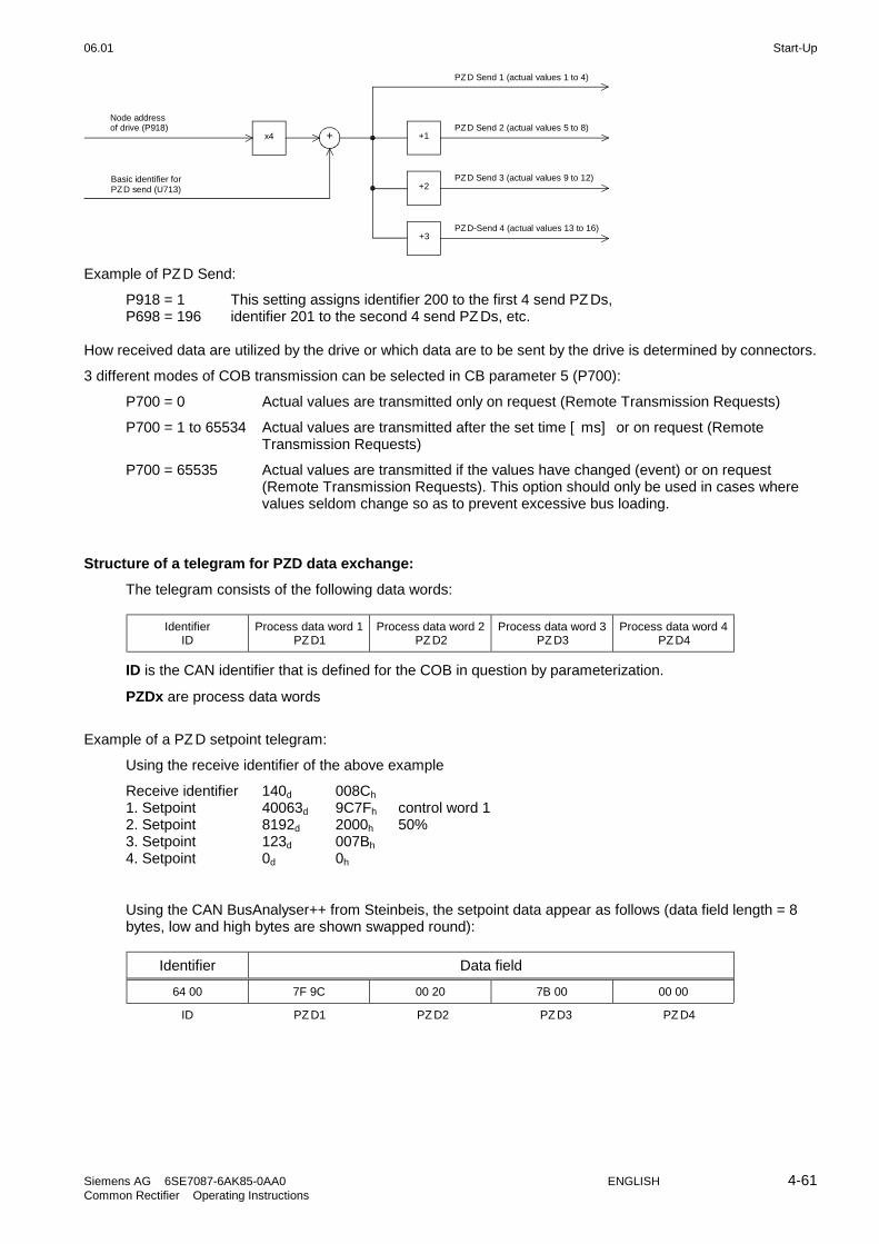
06.01 Start-Up
Siemens AG 6SE7087-6AK85-0AA0 ENGLISH 4-61Common Rectifier Operating Instructions
x4 + +1
+2
+3
Node address of drive (P918)
Basic identifier forPZD send (U713)
PZD Send 2 (actual values 5 to 8)
PZD Send 1 (actual values 1 to 4)
PZD Send 3 (actual values 9 to 12)
PZD-Send 4 (actual values 13 to 16)
Example of PZD Send:
P918 = 1 This setting assigns identifier 200 to the first 4 send PZDs,P698 = 196 identifier 201 to the second 4 send PZDs, etc.
How received data are utilized by the drive or which data are to be sent by the drive is determined by connectors.
3 different modes of COB transmission can be selected in CB parameter 5 (P700):
P700 = 0 Actual values are transmitted only on request (Remote Transmission Requests)
P700 = 1 to 65534 Actual values are transmitted after the set time [ms] or on request (RemoteTransmission Requests)
P700 = 65535 Actual values are transmitted if the values have changed (event) or on request(Remote Transmission Requests). This option should only be used in cases wherevalues seldom change so as to prevent excessive bus loading.
Structure of a telegram for PZD data exchange:
The telegram consists of the following data words:
IdentifierID
Process data word 1PZD1
Process data word 2PZD2
Process data word 3PZD3
Process data word 4PZD4
ID is the CAN identifier that is defined for the COB in question by parameterization.
PZDx are process data words
Example of a PZD setpoint telegram:
Using the receive identifier of the above example
Receive identifier 140d 008Ch
1. Setpoint 40063d 9C7Fh control word 12. Setpoint 8192d 2000h 50%3. Setpoint 123d 007Bh
4. Setpoint 0d 0h
Using the CAN BusAnalyser++ from Steinbeis, the setpoint data appear as follows (data field length = 8bytes, low and high bytes are shown swapped round):
Identifier Data field
64 00 7F 9C 00 20 7B 00 00 00
ID PZD1 PZD2 PZD3 PZD4

Start-Up 06.01
4-62 ENGLISH Siemens AG 6SE7087-6AK85-0AA0Common Rectifier Operating Instructions
The following functions are also available, each allowing a maximum of 16 process data to be transferred:
PZD Receive BroadcastThis function is used to send setpoints and control words from the master to all slaves on the bussimultaneously. With this option, an identical identifier must be set on all slaves utilizing the function. Thiscommon identifier is set in CB parameter 6 (P701). The first 4 PZDs are transferred with the value set inP701 and the second 4 PZDs with the value in P701+1, etc.
PZD Receive MulticastThis function is used to send setpoints and control words from the master to a group of slaves on thebus simultaneously. With this option, all slaves within the group using the function must be set to anidentical identifier. This group identifier is set in CB parameter 7 (P702). The first 4 PZDs are transferredwith the value set in 702 and the second 4 PZDs with the value in 702+1, etc.
PZD Receive InternodeThis function is used to receive setpoints and control words from another slave, allowing PZDs to beexchanged between drives without intervention by a CAN master. For this purpose, the identifier of PZDReceive Internode on the receiving slave must be set to the identifier of PZD Send on the transmittingslave. This identifier is set in CB parameter 8 (P703). The first 4 PZDs are transferred with the value set inP703 and the second 4 PZDs with the value in P703+1, etc.
Notes regarding PZD transmission:
Control word 1 must always be transferred as the first PZD word for setpoints. If control word 2 is needed,then it must be transferred as the fourth PZD word.
Bit 10 (control by PLC) must always be set in control word 1 or else the drives will not accept setpointsand control words.
The consistency of process data can only be guaranteed within a COB. If more than 4 data words areneeded, these must be divided among several COBs. Since drives accept the data asynchronously, thedata transferred in several COBs may not always be accepted and processed in the same processingcycle.For this reason, interrelated data should be transferred within the same COB. If this is not possible, dataconsistency can be assured by means of control word bit 10 (control by PLC), i.e. by setting the bit to "off"in the first COB to temporarily prevent the drive from accepting the data from the communications board.The remaining data are then transmitted. Finally, a COB containing a control word bit 10 set to "on" istransmitted. Since a drive can accept up to 16 PZDs simultaneously from the communication board, dataconsistency is assured.
Since a variety of different functions can be used to transfer PZDs simultaneously, data are overlayed inthe drive. For example, the first PZD from PZD Receive and PZD Receive Broadcast are alwaysinterpreted as the same control word 1. For this reason, care should be taken to ensure that data aretransferred in meaningful combinations.
Two CAN identifiers are required for the purpose of processing parameters, i.e. one CAN identifier for PKWRequest (parameter request job to drive) and one CAN identifier for PKW Response (parameter response bydrive). These assignments are made in CB parameters as shown in the following diagram:
x2 +
+1
Node addressof drive (P918)
Basic identifier forparameterizing (U711)
PKW Request
PKW Response
Example of PKW data exchange:
P918 = 1 This setting assigns identifier 300 to the parameter job (request)P696 = 298 and identifier 301 to the parameter response.

06.01 Start-Up
Siemens AG 6SE7087-6AK85-0AA0 ENGLISH 4-63Common Rectifier Operating Instructions
Structure of a telegram for PKW data exchange:
The telegram consists of the following data words:
IdentifierID
Parameter identifierPKE
Parameter indexIND
Parameter value 1PWE1
Parameter value 2PWE2
ID is the CAN identifier that is defined for the COB in question by parameterization.
PKE contains the request or response ID and the parameter number
Request or response ID Parameter numberPNU
Bit 0 to bit 10 contain the number of the parameter concerned. Bit 12 to bit 15 contain the request orresponse ID.
The index IND contains the value 0 for unindexed parameters, for indexed parameters it contains thecorresponding index value. Bit15 also has a special function as the page select bit for parameter numbersgreater than 1999.The index value 255 means that the request concerns all indices of the parameter in question. For achange request, the parameter values must then be passed on for all indices of the parameter. Because aCOB can only contain up to 4 data words (8 bytes) of net data, use of this request is only possible forparameters with (up to ) 2 indices. In the other direction, the drive supplies all index values in the responsetelegram to a read request.
Details about the telegram structure can be found in Section 4.5.6, "Structure of request/responsetelegrams“.
Example of a PKW request:
Changing the parameter value of the indexed parameter P140.02 (in the RAM) to 5.000Ω.
The example telegram therefore contains the following values:
Request identifier 300d 012Ch for use of the IDs of the example aboveRequest code 7d 7h "Change parameter value (array word)"Parameter number 140d 008Ch => PKE = 708Ch
Index 2d 0002h
Parameter value 5000d 1388h 3 decimal places (value = 5000)
Using the CAN BusAnalyser++ from Steinbeis, the transmit data appear as follows (data field length = 8bytes, low and high bytes are shown swapped round):
Identifier Data field
2C 01 8C 70 02 00 88 13 00 00
ID PKE IND PWE1
The following transfer function is also available:
PKW Request BroadcastA parameter job (request) is processed simultaneously by all slaves on the bus. The node address is notused to generate the CAN identifier because this must be set identically on all slaves utilizing the PKWRequest Broadcast function. This common identifier is set in CB parameter 9 (P704). The correspondingparameter response is made with the CAN identifier for PKW Response described above
Notes regarding PKW transmission:
The length of the job and the response is always 4 words. Jobs which apply to all indices of a parameter(e.g. "Request all indices") are not possible.
As a general rule, the low-order byte (in words) or the low-order word (in double words) is transferred first.SIMOVERT 6SE70 does not use double word parameters itself, these jobs can only be executed whereaccess is available to technology board parameters (e.g. T400).
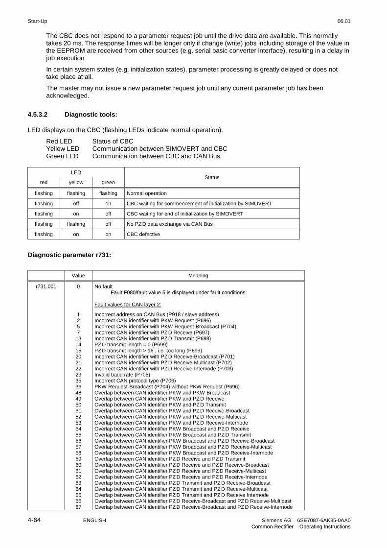
Start-Up 06.01
4-64 ENGLISH Siemens AG 6SE7087-6AK85-0AA0Common Rectifier Operating Instructions
The CBC does not respond to a parameter request job until the drive data are available. This normallytakes 20 ms. The response times will be longer only if change (write) jobs including storage of the value inthe EEPROM are received from other sources (e.g. serial basic converter interface), resulting in a delay injob execution
In certain system states (e.g. initialization states), parameter processing is greatly delayed or does nottake place at all.
The master may not issue a new parameter request job until any current parameter job has beenacknowledged.
4.5.3.2 Diagnostic tools:
LED displays on the CBC (flashing LEDs indicate normal operation):
Red LED Status of CBCYellow LED Communication between SIMOVERT and CBCGreen LED Communication between CBC and CAN Bus
LED
red yellow greenStatus
flashing flashing flashing Normal operation
flashing off on CBC waiting for commencement of initialization by SIMOVERT
flashing on off CBC waiting for end of initialization by SIMOVERT
flashing flashing off No PZD data exchange via CAN Bus
flashing on on CBC defective
Diagnostic parameter r731:
Value Meaning
r731.001 0
12571314152021222335364849505152535455565758596061626364656667
No faultFault F080/fault value 5 is displayed under fault conditions:
Fault values for CAN layer 2:
Incorrect address on CAN Bus (P918 / slave address)Incorrect CAN identifier with PKW Request (P696)Incorrect CAN identifier with PKW Request-Broadcast (P704)Incorrect CAN identifier with PZD Receive (P697)Incorrect CAN identifier with PZD Transmit (P698)PZD transmit length = 0 (P699)PZD transmit length > 16 , i.e. too long (P699)Incorrect CAN identifier with PZD Receive-Broadcast (P701)Incorrect CAN identifier with PZD Receive-Multicast (P702)Incorrect CAN identifier with PZD Receive-Internode (P703)Invalid baud rate (P705)Incorrect CAN protocol type (P706)PKW Request-Broadcast (P704) without PKW Request (P696)Overlap between CAN identifier PKW and PKW BroadcastOverlap between CAN identifier PKW and PZD ReceiveOverlap between CAN identifier PKW and PZD TransmitOverlap between CAN identifier PKW and PZD Receive-BroadcastOverlap between CAN identifier PKW and PZD Receive-MulticastOverlap between CAN identifier PKW and PZD Receive-InternodeOverlap between CAN identifier PKW Broadcast and PZD ReceiveOverlap between CAN identifier PKW Broadcast and PZD TransmitOverlap between CAN identifier PKW Broadcast and PZD Receive-BroadcastOverlap between CAN identifier PKW Broadcast and PZD Receive-MulticastOverlap between CAN identifier PKW Broadcast and PZD Receive-InternodeOverlap between CAN identifier PZD Receive and PZD TransmitOverlap between CAN identifier PZD Receive and PZD Receive-BroadcastOverlap between CAN identifier PZD Receive and PZD Receive-MulticastOverlap between CAN identifier PZD Receive and PZD Receive-InternodeOverlap between CAN identifier PZD Transmit and PZD Receive-BroadcastOverlap between CAN identifier PZD Transmit and PZD Receive-MulticastOverlap between CAN identifier PZD Transmit and PZD Receive InternodeOverlap between CAN identifier PZD Receive-Broadcast and PZD Receive-MulticastOverlap between CAN identifier PZD Receive-Broadcast and PZD Receive-Internode

06.01 Start-Up
Siemens AG 6SE7087-6AK85-0AA0 ENGLISH 4-65Common Rectifier Operating Instructions
Value Meaning
68
12335
25725827327451351452953076977078578610251026104110421092
Overlap between CAN identifier PZD Receive-Multicast and PZD Receive-Internode
Fault values for CANopen:
Incorrect bus address (P918)Invalid baud rate (P705)Incorrect CAN protocol type (P706)Invalid mapping of 1st Receive PDO (P696)Invalid transmission type of 1st Receive PDO (P696)Invalid mapping of 1st Transmit PDO (P700)Invalid transmission type of 1st Transmit PDO (P700)Invalid mapping of 2nd Receive PDO (P697)Invalid transmission type of 2nd Receive PDO (P697)Invalid mapping of 2nd Transmit PDO (P701)Invalid transmission type of 2nd Transmit PDO (P701)Invalid mapping of 3rd Receive PDO (P698)Invalid transmission type of 3rd Receive PDO (P698)Invalid mapping of 3rd Transmit PDO (P702)Invalid transmission type of 3rd Transmit PDO (P702)Invalid mapping of 4th Receive PDO (P699)Invalid transmission type of 4th Receive PDO (P699)Invalid mapping of 4th Transmit PDO (P703)Invalid transmission type of 4th Transmit PDO (P703)Invalid Life Time Event or incorrect basic unit parameterized (P704)
r731.002 Number of correctly received PZD CAN telegrams since Power ON
r731.003 Number of PZD telegrams lost since Power ONTelegrams will be lost if the CAN Bus master sends PZD telegrams faster than they canbe processed by the slave.
r731.004 Counter of Bus Off states since Power ON (alarm A084)
r731.005 Counter of Error Warning states since Power ON (alarm A083)
r731.010 Number of correctly transmitted PZD CAN telegrams since Power ON
r731.011 Number of errors during transmission of PZD telegramsPZD telegrams cannot be transmitted when the bus is overloaded
r731.014 Number of correctly processed PKW requests and responses since Power ON
r731.015 Number of PKW request processing errors, e.g. owing to bus overload or missingresponses from CUD1 (see below for error type)
r731.016091112
Type of PKW request processing error:No errorError transmitting the PKW response (while waiting for a free channel)Timeout waiting for the PKW response from the CUD1Timeout waiting for a free channel (bus overload)
r731.018 Number of lost PKW requests
r731.026 Software version of CBC(e.g. "12“ = version 1.2, see also r720)
r731.027 Software identifier(extended software version identifier, see also r722)
r731.028 Date of generation of CBC softwareDay (H byte) and month (L byte)
r731.029 Date of generation of CBC softwareYear
Fault and alarm messages:
Detailed information about fault messages can be found in Section 7.
Fault F080An error occurred during initialization of the CBC board, e.g. incorrect setting of a CB parameter, incorrectbus address or defective board.
Fault F081The heartbeat counter (counter on CBC) which is monitored by SIMOVERT for "signs of life" from theboard has not changed for at least 800 ms.
Fault F082Failure of PZD telegrams or a fault in the transmission channel.

Start-Up 06.01
4-66 ENGLISH Siemens AG 6SE7087-6AK85-0AA0Common Rectifier Operating Instructions
Alarm A083 (Error Warning)Errored telegrams are being received or sent and the error counter on the supplementary board hasexceeded the alarm limit.Errored telegrams are ignored. The data most recently transferred remain valid. If the errored telegramscontain process data, fault message F082 with fault value 10 may be activated as a function of thetelegram failure time set in P695. No fault message is generated for PKW data.
Alarm A084 (Bus Off)Errored telegrams are being received or sent and the error counter on the supplementary board hasexceeded the fault limit.Errored telegrams are ignored. The data most recently transferred remain valid. If the errored telegramscontain process data, fault message F082 with fault value 10 may be activated as a function of thetelegram failure time set in P695. No fault message is generated for PKW data.

06.01 Start-Up
Siemens AG 6SE7087-6AK85-0AA0 ENGLISH 4-67Common Rectifier Operating Instructions
4.5.4 Sequence of operations for starting up the serial I/O board SCB1:
1 With the power supply disconnected, insert the SCB1 board into slot 2 (or, if you have installed atechnology board, into slot 3).
2 Set bus address on SCI using DIP-Fix switch S1 (each SCI slave requires its own address number):
Slave 1 Slave 2
Address number 1 2
Switch setting S1 closed open
3 Mount the interface board(s) on the rail, make the connection to the 24 V power supply and the fiber opticconnection between SCB1 and SCI.
Depending on the type of SCI slaves used and the functions required, the following parameters arerelevant with respect to board operation (for details, see the parameter list in Section 5 and operatinginstructions for the boards):
- P660 Configuration of analog inputs of SCI1 slavesThe type of input signal for each input is parameterized via the indices.
- P661 Filter time constant of analog inputs of SCI1 slavesFiltering of the input signal for each input is parameterized via the indices.
- P662 Offset compensation of analog inputs of SCI1 slavesThe input signal for each input is zero calibrated via the indices.
- P664 Actual value output via analog outputs of SCI1 slavesA connector number is selected via the indices to define the output quantity at each output.
- P665 Gain of analog outputs of SCI1 slavesThe gain for each output is parameterized via the indices.
- P666 Offset compensation of analog outputs of SCI1 slavesThe output signal for each output is zero calibrated via the indices.
- P682 SCB protocolSelection of operating mode of the SCB1 board (master for SCI slaves or peer-to-peercommunication via fiber optic cable).
- P684.2 SCB baud rateSelection of transmission rate at which the peer-to-peer interface of the SCB1 should operate(P682 = 3).
- P687.2 SCB telegram failure timeSelection of telegram failure time for the peer-to-peer protocol.
- P689.2 SCB peer forwardingIdentifies words in the received peer-to-peer telegram that should be forwarded immediately.
- P690i SCB actual valuesSelection of parameter values that should be transmitted via the serial interface of the SCBboard.
- P090 or P091 for logging the board
- The display parameter r730 (diagnostic information) assists in the correction of problems during start-up.

Start-Up 06.01
4-68 ENGLISH Siemens AG 6SE7087-6AK85-0AA0Common Rectifier Operating Instructions
4 Switching off and on of the electronics supply voltage. Doing this causes the values of the parameterslisted above to be transferred from the supplementary board.
The optional board SCB1 (Serial Communication Board 1) is used
- as Master of SCI1 and SCI2 slaves (Serial Communication Interface).
- for communication via the peer-to-peer interface.
In both cases, communication between the boards takes place via fiber optic cables (recommended:Siemens plastic fiber optic cable, CA-1V2YP980/1000,200A or Siemens fiber optic cable with glass core,CLY-1V01S200/230,10A)
4.5.4.1 SCB1 as master for SCI1 and SCI2
The SCI boards can be used if additional terminals are required or if safe electrical isolation via fiber optic cableis a mandatory requirement.This board only allows the SCB1 master to exchange data with the SCI slaves. Data cannot be exchangedbetween the SCI slaves themselves.
A maximum of 2 SCIs, of either the same or different types, can be connected to the SCB1.
SCI1 or SCI2 are terminal expansion boards which are mounted on a rail outside the SIMOVERT 6SE70 masterand supplied with 24 V DC voltage (-17% +25%, 1A) from an external source.
The interface boards extend the converter by the following additional inputs/outputs:
SCI1 SCI2
10 binary inputs 16 binary inputs
8 binary outputs 12 binary outputs
3 analog inputs
3 analog outputs
Reception of SCI data by the SCB1 or transmission to the SCIs is synchronized, i.e. the data of two slaves isreceived simultaneously or transmitted simultaneously.
Details of the input/output functions and connections can be found in the operating instructions for the boards.
CAUTION
SCI boards have no external enclosure to protect them against direct contact or ingress ofpollutants. To protect them against damage, they must be installed in a housing or in thecontrol cabinet of a higher-level system.
The maximum permissible length of fiber optic cables is 10m.
An input filter must be fitted for the external power supply of the interface boards.
Ground SCI at X80 using a short lead.
Analog inputs on SCI1: Only the voltage input or the current input may be used for eachchannel.
Analog outputs on SCI1: Only the voltage input or the current input may be used for eachchannel. The outputs are short-circuit-proof.
The binary driver outputs are short-circuit-proof. Relays may only be connected to theseoutputs in conjunction with an external power supply.
The binary relay outputs are not designed for protective separation.
To protect them against static discharge, the boards may only be placed on conductivesurfaces.

06.01 Start-Up
Siemens AG 6SE7087-6AK85-0AA0 ENGLISH 4-69Common Rectifier Operating Instructions
Recommended circuit for connecting SCB1 to SCI1 and SCI2 using fiber optic cables:
SCB1
SCI2SCI1
U121 U125
U425 U421 U435 U431
X427 X437
24V
WARNING
If the 24 V voltage supply for an SCI slave fails which data are being exchangedbetween the SCB1 and an SCI, then the "1" signal applied at a binary input is sent tothe SCB1 or SIMOVERT 6SE70 as an "0" shortly before the power finally fails.In contrast, the "1" remains applied in the SIMOVERT 6SE70 in the event of aninterruption in the fiber optic connection.
4.5.4.2 SCB1 as peer-to-peer interface
Process data can be passed quickly in a train from unit to unit (between SCB1 master boards) via the peer-to-peer interface. The transferred data cannot be manipulated (e.g. multiplication by a factor).
4.5.4.3 Diagnostic tools:
LED display on SCB1:
LED on Reset stateLED flashing Normal operationLED off Error
LED display on SCI1 or SCI2 slave:
LED on Reset stateLED flashing 12Hz frequency No telegram traffic (e.g. fiber optic cable not
connected)5Hz frequency Faulty telegram traffic (e.g. fiber optic ring
interrupted or other slave has no supplyvoltage)
0.5Hz frequency Normal operationLED off Error
Details about fault or alarm messages which may occur in relation to SCB1 or SCI (F070 to F079 and A049 toA053) can be found in Section 7.

Start-Up 06.01
4-70 ENGLISH Siemens AG 6SE7087-6AK85-0AA0Common Rectifier Operating Instructions
4.5.5 Sequence of operations for starting up the board SCB2:
1 With the power supply disconnected, insert the SCB2 board into slot 2 (or, if you have installed atechnology board, into slot 3).
2 The following parameters are important for operation (for details, see parameter list in Section 5 andoperating instructions for the SCB2):
- P682 SCB protocolSelection of operating mode for the SCB2 interface
- P683.2 SCB bus addressSelection of bus address at which the SCB2 can be addressed via the USS bus (P682 = 1 or 2)
- P684.2 SCB Baud rateSelection of transmission rate with which the USS interface (P682 = 1 or 2) or peer-to-peerinterface (P682 = 3) of the SCB2 should be operated
- P685.2 SCB PKW numberSelection of number of words (16 bit) of the PKW part in the net data block of the USS telegram(P682 = 1 or 2)
- P686.2 SCB PZD numberSelection of number of words (16 bit) of the PZD part in the net data block of the USS telegram(P682 = 1 or 2)
- P687.2 SCB telegram failure timeSelection of telegram failure time for the USS or peer-to-peer protocol
- P689.2 SCB peer forwardingIdentifies words in the received peer-to-peer telegram that should be forwarded immediately
- P690i SCB actual valuesSelection of parameter values that should be transmitted via the serial interface of the SCB2board
- r730i SCB diagnosisSCB diagnostic information
- P090 or P091 for logging the board
- The display parameter r730 (diagnostic information) assists in the correction of problems duringcommissioning.
3 Switching off and on of the electronics supply voltage. Doing this causes the values of the parameterslisted above to be transferred from the supplementary board.
The optional board SCB2 (Serial Communication Board 2) provides an additional serial interface usingeither the USS or peer-to-peer protocol.
With the USS protocol, up to 31 slaves (converters) can be controlled by a master. In this case, the busterminating resistors on the last bus node must be connected by closing the switch S1 in order to preventtransmission faults.
The peer-to-peer protocol allows data to be forwarded quickly from unit to unit (e.g. for implementing asetpoint cascade).

06.01 Start-Up
Siemens AG 6SE7087-6AK85-0AA0 ENGLISH 4-71Common Rectifier Operating Instructions
4.5.6 Structure of request/response telegrams
There is no basic difference between the useful data area in the request and response telegrams for PROFIBUSand CAN Bus. The only difference between the two types of bus telegram is in the protocol frame and thetransmission sequence of H and L bytes. The structure of the protocol frame and the transmission sequence ofbytes are therefore described where necessary in the sections containing the start-up description for theappropriate board.
Each request and each response basically comprises three areas apart from the telegram frame with headerand trailer:
Header TrailerIndexIND
Parameter valuePWE
Parameter identifierPKE
The parameter identifier (PKE) contains a request or response identifier (i.e. type of request or response) andthe number of the addressed parameter. The spontaneous signaling bit SPM (bit11) is not used on theSIMOVERT 6SE70 Common Rectifier.
Header TrailerIndexIND
SPM
Parameter valuePWE
Parameter identifierPKE
Task/ response identifier
Parameter number (PNU)
Bits 0 to 10 contain the number of the parameter specified in the request.
Parameter number (PNU):
Parameter area Displayednumber
Input on OP1S PNU in parameteridentifier
Basic unit Pxxx, rxxx 0 - 999 0 - 999
Technology board Hxxx, dxxx 1000 - 1999 1000 - 1999

Start-Up 06.01
4-72 ENGLISH Siemens AG 6SE7087-6AK85-0AA0Common Rectifier Operating Instructions
Bit 12 bis Bit 15 enthalten die Auftragskennung bzw. die dazugehörende Antwortkennung entsprechend derfolgenden Liste:
Response identifierRequestidentifier
Meaning
positive negative
0 No request 0
1 Request parameter value (word or double word) 1 or 2
2 Modify parameter value (word) 1
3 Modify parameter value (double word) 2
4 Request descriptive element 3
5 Reserved -
6 Request parameter value (array) (word or double word) 4 or 5
7 Modify parameter value (array - word) 4
8 Modify parameter value (array-double word) 5
9 Request number of array elements 6
10 Reserved -
11 Modify parameter value (array-double word) and store in EEPROM 5
12 Modify parameter value (array-word) and store in EEPROM 4
13 Modify parameter value (double word) and store in EEPROM 2
14 Modify parameter value (double word) and store in EEPROM 1
15 Request text 15
7 or 8
If the common rectifier has been unable to process the request, it does not return the associated responseidentifier, but error identifier 7 (or 8) instead.In this case, an error code defining the error in more detail as shown in the following list is returned as aparameter value:
Error code Meaning
0 Illegal parameter number (PNU) No PNU specified
1 Parameter value cannot be modified Visualization parameter
2 Lower or upper value limit violated
3 Faulty subindex
4 Parameter is not indexed (no array)
5 Parameter is not indexed (no array)
6 Parameter value can only be reset
7 Descriptive element cannot be modified
8 PPO Write (acc. to "Information Report") is not available
9 Parameter description is not available
10 Incorrect access level
11 No parameterizing enable (P927)
12 Keyword missing Key parameter P051 incorrectly set
13 Text cannot be read cyclically
15 No text
16 PPO Write missing
17 Incorrect operating state
19 Value cannot be read cyclically
101 Parameter number currently deactivated
102 Channel not wide enough
103 PKW number incorrect Applies only to serial interfaces

06.01 Start-Up
Siemens AG 6SE7087-6AK85-0AA0 ENGLISH 4-73Common Rectifier Operating Instructions
Error code Meaning
104 Illegal parameter value Applies to BiCo selection parameters
105 Indexed parameter
106 Request not implemented in drive
107 Text cannot be modified
108 Incorrect number of parameter values Applies to "Change all indices" request
The index IND contains a "0" for non-indexed parameters; a 8-bit long index value is entered (in the low-orderbyte) for indexed parameters.Exception: In the case of cyclical PROFIBUS services, the L and H byte sequence is reversed (see "Start-up ofPROFIBUS boards").
Header TrailerIndexIND
Bit15
Parameter valuePWE
Parameter identifierPKE
Index, L byteIndex, H byte
An index value of 255 means that the request applies to all indices of the relevant parameter. In the case of amodification request, the parameter values for all indices of the parameter must be transferred. Conversely, thedrive supplies all index values in its response to a read request.
The parameter value PWE is treated like a double word (PWE1 and PWE2). The high word is set to 0 when asingle word is transferred.
Header TrailerIndexIND
PWE2PWE1
Parameter valuePWE
Parameter identifierPKE

Start-Up 06.01
4-74 ENGLISH Siemens AG 6SE7087-6AK85-0AA0Common Rectifier Operating Instructions

06.01 Parameter List
Siemens AG 6SE7087-6AK85-0AA0 ENGLISH 5-1Common Rectifier Operating Instructions
5 Parameter List
Parameter list - Overview
Range of ParameterNumbers
Function
000 Operation Display
001 - 049 General Observation Parameters
050 - 069 General Parameters
070 - 089 Drive Data
090 - 099 Hardware Configuration
100 - 149 DC Link Data
150 - 329 Control
330 - 409 Convenience functions
410 - 549 Setpoint Channel
550 - 649 Control and Status Word
650 - 679 Analog Input/Output
680 - 719 Communications
720 - 759 Diagnostics
760 - 779 Modulator
780 - 799 Factory Parameters
900 - 999 Profile Parameters (Profibus)
NOTE
The software used for the power supply unit is identical to that used for the power supply and regenerativepower supply units of the equipment series 6SE70.
The functional difference between power supply units and combined power supply and regenerative units isdefined by means of the parameter P070.
Any remarks concerning "regeneration" in these operating instructions (e.g. concerning control word 1) shouldbe ignored.

Parameter List 06.01
5-2 ENGLISH Siemens AG 6SE7087-6AK85-0AA0Common Rectifier Operating Instructions
Parameter list; Summary of the abbreviations
Example:
PNU
* : Conf. Par.
OP1S - Parameter name
Description
Value range[phys. unit]Selection text
DisplayIndicesFactorysetting
SeeModify(access/status)
P329
1)
8)
Pre-charging time
Pre-charging time of the DC link
RDS parameter2)
PNU=149Hex; Type=O2;3)Scaling: 1Hex =∧ 14)
0 to 9999[ms]
45009)
35)/ BR6)
3/ BR7)
1) An * under the parameter number means that this is a confirmation parameter, i.e. the modified value does not become active until theP key is pressed.
2) Abbreviations for indexed parameters
RDS Reserve data set parameter with 4 indices; changeover with control word 2, bits 18 and 19G/R Parameter with changeover feature for basic and reserve setting in control word 2, bit 30
3) Specification of parameter typeO2 16-bit value without signI2 16-bit value with signV2 Bit-coded quantityL2 Nibble-coded quantity
4) Scaling for access via the PKW mechanismIf necessary: Specification of scaling group for process data (PZD)
PZD group PZD scaling0 or no specification As for PKW scaling1 4000Hex = 100%
5) Access stage (P051), starting at which a parameter can be modified or displayed
1 Operator input2 Standard mode3 Expert mode4 Factory-set parameters
6) Specification of the operating states in which the parameter can be displayed
7) Specification of the operating states in which the parameter can be displayed
6) 7) Operating states:U MLFB input o000H Hardware
configuration
o002, o004
A Drive setting o005B Ready (incl.: fault ) o007, o008, o009,
o010, o011, o012, o021R (R) Run o014, o015, o018
8) An ** under the parameter number means that this parameter does not exist with a 6SE70 rectifier unit (P070 (MLFB) 101).
9) A factory setting value in brackets means that the specified value only applies for P077=0. See Section 4.3.9.1 "Generate factory setting"for more details.

06.01 Parameter List
Siemens AG 6SE7087-6AK85-0AA0 ENGLISH 5-3Common Rectifier Operating Instructions
PNU
* : Conf. Par.
OP1S parameter name
Description
Value range[phys. unit]Selection text
DisplayIndicesFactory-setting
SeeModify(access /status)
5.1 Operation display
r000 Operation Display
Status display, faults and warnings of the S/F unitFor description, see Chapter 6 Operator control
o014 Run- - No thyristor bridge in circuitI Rectifier bridge in circuitII Regenerative bridge in circuit
o012 Test phaseWait until the thyristor test and/or earth-fault test has beencompleted (Selection function: P353≠0 and/or P354≠0).Note: The thyristor test can only be conducted if the DC linkvoltage is less than 5% of 1.35*P071. Following an ONcommand, therefore, wait in operating status o012 until thiscondition is satisfied!
o011 Wait for Run enableWait for Run enable
o010 Wait for system voltageWait until the system voltage has been checked.
or Wait for voltage at power terminals X1-U1, X1-V1, X1-W1(rectifier bridge)
or Wait for voltage at power terminals X4-1U2, X4-1V2, X4-1W2(regenerative bridge)
or Wait for checkback signal "System contactor energized"or Waiting state before energizing the system contactor (Waiting
time P409)
o009 Wait for Ready to Switch OnWait for Ready to Switch On (OFF1 active)
or Wait until internal OFF state is canceled by an external OFFcommand.
o008 Switch-on inhibit; isolation (OFF2)Wait for acknowledgment of switch-on inhibit by activating theSWITCH-OFF command
or Isolation implemented (OFF2)or Wait until a valid USS telegram to SST1 has been received
(only if P687 is set to ≠0)or Wait until a valid peer-to-peer telegram to SST2 has been
received (only for P688=1, when P687.i003 is set to ≠0)
o007 FaultA fault message has been received.
o021 DownloadA parameter download over SST1 can be executed
o005 Drive settings
o004 Hardware settings
o002 Electronics initializationThe option module electronics are initialized
or The basic unit electronics are initialized
o001 Establish factory setting
o000 Set MLFB
PNU=00Hex; Type=O2; Scaling: 1Hex =∧ 1
0 to 21 --
1/UHABR

Parameter List 06.01
5-4 ENGLISH Siemens AG 6SE7087-6AK85-0AA0Common Rectifier Operating Instructions
PNU
* : Conf. Par.
OP1S parameter name
Description
Value range[phys. unit]Selection text
DisplayIndicesFactory-setting
SeeModify(access /status)
5.2 General observation parameters
r001 Status
Observation parameters for the current status of the S/F unit
0 = Enter MLFB (P070) (U) 1 = Establish factory setting 2 = Hardware initialization (H) 4 = Hardware settings (H) 5 = Drive system settings (A) 7 = Fault (B) 8 = Restart inhibit (B) 9 = Ready for turn-ON (B)10 = Wait for system voltage (B)11 = Ready for operation (B)12 = Ground fault test (B)14 = R/R unit is in operation (R)15 = Ramp generator decelerating (OFF1) (R)18 = Circuit identification or forming (R)21 = Download of parameter settings (B)
PNU=1Hex; Type=O2; Scaling: 1Hex =∧ 1
0 to 21
MLFB-InputInit. RFEInitHW ConfHW Config.System Set.FaultON LockedReady for ONLine VoltageReady OperGrndFltTestOperationOFF 1Circuit IDDownload
- 2/UHABR
r006 DC Bus Volts
Actual DC link voltage
PNU=6Hex; Type=I2; Scaling: 1Hex =∧ 1 V
0 - 100% =∧ 0 to 16384V
0 to 1000[V]
--
2/ BR
r011 Heatsink Temp
Temperature of the heat sink
PNU=0BHex; Type=I2; Scalling: 1Hex =∧ 1 °C PZD gr.: 1
Analog output: +/-100% =∧ +/-100 °C
-53 to 199[°C]
--
3/ BR
r012 Base/Reserve
Base / reserve settings of the process data wiring for control word bits
0: Base setting1: Reserve setting
PNU=0CHex; Type=O2; Scaling: 1Hex =∧ 1
0 to 1 --
2/ BR
r013 Operat. Hours
Display of operating hours with firing pulses enabled (Run status).All times > about 0.1s are taken into account.
i001 = days (0..9999)i002 = hours (0..24)i003 = seconds (0..3600)
The operating hours counter r013 is set to 0 when the factory setting isestablished (P052=1).
PNU=0DHex; Type=O2; Scaling: 1Hex =∧ 1
dhs
3-
2/ BR
r030 Rectifier Volts
Display of the system voltage at the rectifier bridge (phase W-U)
PNU=1EHex; Type=O2; Scaling: 1Hex =∧ 0.1 V
0 - 100% =∧ 0 to 1638.4V
0.0 to 1000.0[V]
--
2/ BR
r031 Inverter Volts
Display of the system voltage at the regenerative bridge (average value ofthe three phases)
PNU=1FHex; Type=O2; Scaling: 1Hex =∧ 0.1 V
0 - 100% =∧ 0 to 1638.4V
0.0 to 1000.0[V]
--
2/ BR

06.01 Parameter List
Siemens AG 6SE7087-6AK85-0AA0 ENGLISH 5-5Common Rectifier Operating Instructions
PNU
* : Conf. Par.
OP1S parameter name
Description
Value range[phys. unit]Selection text
DisplayIndicesFactory-setting
SeeModify(access /status)
r032 Line Frequency
Display of the line frequency
PNU=20Hex; Type=O2; Scaling: 1Hex =∧ 0.01 Hz,
0 - 100% =∧ 0 to 50 Hz PZD gr.: 1
0.01 to 65.00[Hz]
--
2/ BR
r033 Firing Angle
Display of the firing angle
PNU=21Hex; Type=O2; Scaling: 1Hex =∧ 0.1 °el,
0 - 100% =∧ 0°el -180°el PZD gr.: 1
0.0 to 165.0[°el]
--
2/ BR
r034 DC Amps (set)
Display of DC link current setpoint
PNU=22Hex; Type=I2; Scaling: 1Hex =∧ 0.1 %, ±100% =∧ ±P075PZD gr.: 1
-150 to 150[%]
--
3/ BR
r035 DC Amps (act)
Display of actual DC link current
PNU=23Hex; Type=I2; Scaling: 1Hex =∧ 1 %, ± 100% =∧ ± P075PZD gr.: 1
-199 to 199[%]
--
2/ BR
r036 DC Volts (set)
Display of DC link voltage setpointThe setpoint 1.35*r030, limited to values of P074 up to 106.8%.
PNU=24Hex; Type=O2; Scaling: 1Hex =∧ 1 %, 100% =∧ 1.35*P071PZD gr.: 1
0 to 199[%]
--
3/ BR
r037 DC Volts (act)
Display of actual DC link voltage
PNU=25Hex; Type=O2; Scaling: 1Hex =∧ 1 %, 100% =∧ 1.35*P071PZD gr.: 1
0 to 199[%]
--
2/ BR
r038 DC Volts Deviat.
Display of setpoint/actual-value deviation of DC link voltage controller
PNU=26Hex; Type=I2; Scaling: 1Hex =∧ 1 %, 100% =∧ 1.35*P071PZD gr.: 1
-199.9 to 199.9[%]
--
3/ BR
r039 AnalogOut Displ.
Display of terminal X102-14 (analog output)
PNU=27Hex; Type=O2; Scaling: 1Hex =∧ 0.1, ± 100% =∧ ±10V at terminal X102-14
PZD gr.: 1
-112.1 to 112.1[%]
--
2/ BR

Parameter List 06.01
5-6 ENGLISH Siemens AG 6SE7087-6AK85-0AA0Common Rectifier Operating Instructions
PNU
* : Conf. Par.
OP1S parameter name
Description
Value range[phys. unit]Selection text
DisplayIndicesFactory-setting
SeeModify(access /status)
5.3 General parameters
P050
*
Language
Display language on the optional operation panel OP
0: German 3: Français1: English 4: Italiano2: Espanol
PNU=32Hex; Type=O2; Scaling: 1Hex =∧ 1
0 to 4
GermanEnglishEspanolFrançaisItaliano
-0
2/UHABR2/ HABR
P051
*
Access Level
Setting of access levels; with higher access levels more parameters can beread and/or written.
1: Operating via PMU or OP2: Standard mode3: Expert mode
PNU=33Hex; Type=O2; Scaling: 1Hex =∧ 1
1 to 3
OperationStandardExpert
-2
1/UHABR1/UHABR
P052
*
Function Select
Selection of several commissioning steps and special functions.(See Section 4.3.9 for details)
0 = Return from on of the functions described below to the previousstatus of the R/R unit
1 = Parameter-Reset: all parameters are reset to their originalsettings (factory settings).According to the Profibus profile for variable speed drives thisfunction is also accessible via parameter P970. After finishingthis function the parameter is automatically reset to 0.
2 = Release for MLFB setting (changing into the status 'MLFBinput'). To exit this function the parameter must be reset to 0.
3 = Upread/Download (Changing into the status'Upread/Download'). To exit this function the parameter must bereset to 0.
4 = Hardware configuration (Changing into the status 'Hardwaresettings'). To exit this function the parameter must be reset to 0.
5 = Drive setting (change to the status "Drive setting" for assigningthe plant data parameters. To exit this function the parametermust be reset to 0.
20 = Forming of the DC link21 = Circuit identification: Assigning the controller parameters of the
R/R unit22 = Display only parameters with modified values
Important: This function can only be used in conjunction withoperator control from the PMU. To exit this function theparameter must be reset to 0 (Return).
PNU=34Hex; Type=O2; Scaling: 1Hex =∧ 1
0 to 22
Return
Param.Reset
Input MLFB
Upread/Download
HW Config.
System Set.
FormingCapsCircuit ID
Changed Par
-0
2/UHABR2/UHAB
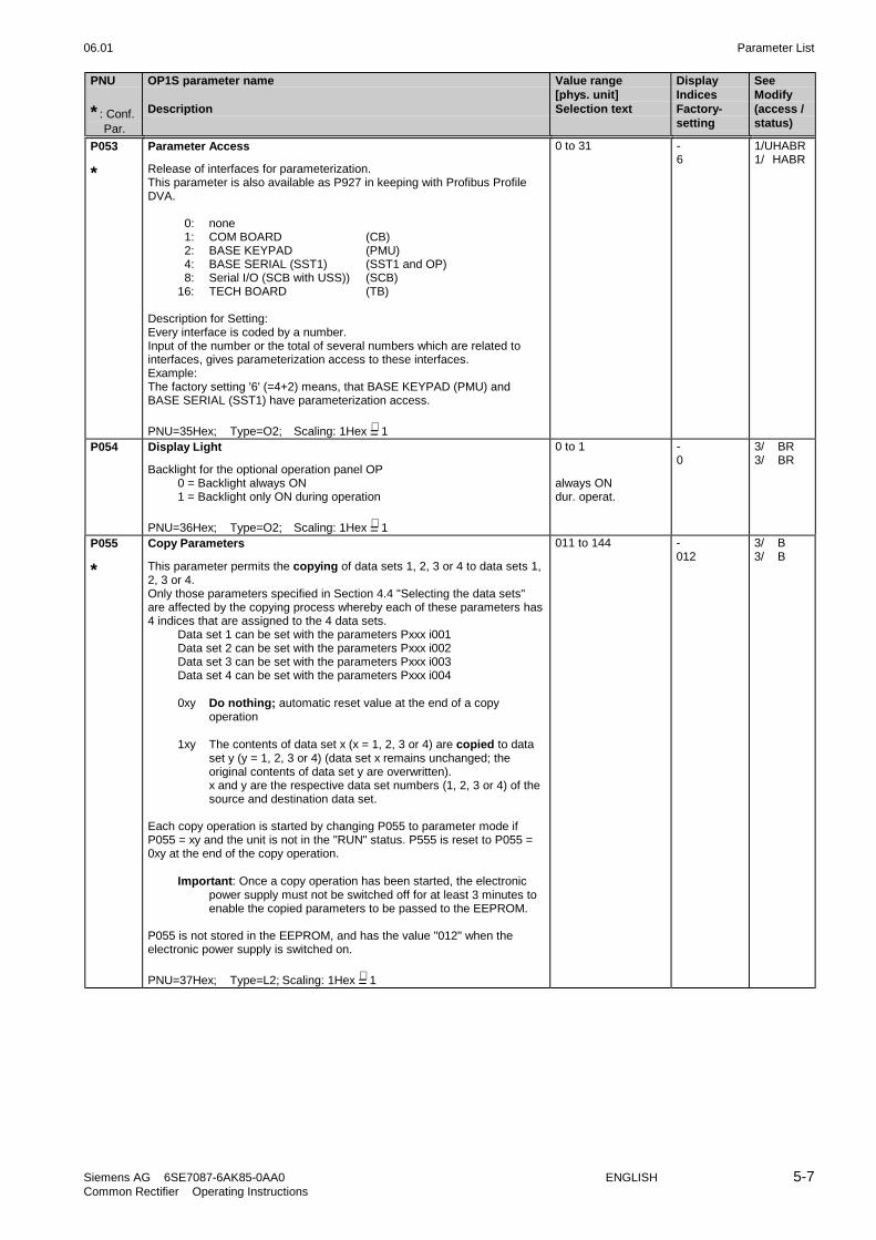
06.01 Parameter List
Siemens AG 6SE7087-6AK85-0AA0 ENGLISH 5-7Common Rectifier Operating Instructions
PNU
* : Conf. Par.
OP1S parameter name
Description
Value range[phys. unit]Selection text
DisplayIndicesFactory-setting
SeeModify(access /status)
P053
*
Parameter Access
Release of interfaces for parameterization.This parameter is also available as P927 in keeping with Profibus ProfileDVA.
0: none 1: COM BOARD (CB) 2: BASE KEYPAD (PMU) 4: BASE SERIAL (SST1) (SST1 and OP) 8: Serial I/O (SCB with USS)) (SCB)16: TECH BOARD (TB)
Description for Setting:Every interface is coded by a number.Input of the number or the total of several numbers which are related tointerfaces, gives parameterization access to these interfaces.Example:The factory setting '6' (=4+2) means, that BASE KEYPAD (PMU) andBASE SERIAL (SST1) have parameterization access.
PNU=35Hex; Type=O2; Scaling: 1Hex =∧ 1
0 to 31 -6
1/UHABR1/ HABR
P054 Display Light
Backlight for the optional operation panel OP0 = Backlight always ON1 = Backlight only ON during operation
PNU=36Hex; Type=O2; Scaling: 1Hex =∧ 1
0 to 1
always ONdur. operat.
-0
3/ BR3/ BR
P055
*
Copy Parameters
This parameter permits the copying of data sets 1, 2, 3 or 4 to data sets 1,2, 3 or 4.Only those parameters specified in Section 4.4 "Selecting the data sets"are affected by the copying process whereby each of these parameters has4 indices that are assigned to the 4 data sets.
Data set 1 can be set with the parameters Pxxx i001Data set 2 can be set with the parameters Pxxx i002Data set 3 can be set with the parameters Pxxx i003Data set 4 can be set with the parameters Pxxx i004
0xy Do nothing; automatic reset value at the end of a copyoperation
1xy The contents of data set x (x = 1, 2, 3 or 4) are copied to dataset y (y = 1, 2, 3 or 4) (data set x remains unchanged; theoriginal contents of data set y are overwritten).x and y are the respective data set numbers (1, 2, 3 or 4) of thesource and destination data set.
Each copy operation is started by changing P055 to parameter mode ifP055 = xy and the unit is not in the "RUN" status. P555 is reset to P055 =0xy at the end of the copy operation.
Important: Once a copy operation has been started, the electronicpower supply must not be switched off for at least 3 minutes toenable the copied parameters to be passed to the EEPROM.
P055 is not stored in the EEPROM, and has the value "012" when theelectronic power supply is switched on.
PNU=37Hex; Type=L2; Scaling: 1Hex =∧ 1
011 to 144 -012
3/ B3/ B

Parameter List 06.01
5-8 ENGLISH Siemens AG 6SE7087-6AK85-0AA0Common Rectifier Operating Instructions
PNU
* : Conf. Par.
OP1S parameter name
Description
Value range[phys. unit]Selection text
DisplayIndiesFactory-setting
SeeModify(access /status
5.4 Drive data
P070
*
MLFB(6SE70 ... )
MLFB (order number) of the rectifier/regenerating unit
On POWER ON, the "Bootstrap" function is automatically selected aslong as P070 has not been set!
Enter the code of the corresponding MLFB here (see Section 4.3.9.2)
PNU=46Hex; Type=O2; Scaling: 1Hex =∧ 1
0 to 120 -Depends onunit
3/U BR3/U
P071
*
Line Volts
Line voltage of the rectifier bridgeRMS value of the rated voltage at which the power section is actuallyoperated
PNU=47Hex; Type=O2; Scaling: 1Hex =∧ 1
100 to 1000[V]
-acc. to P070
2/ ABR2/ A
P074 Limit LowVoltage
Response threshold for undervoltage disconnection and phase failuremonitoring and threshold for DC link voltage (ssee Section 4.3.10.1).
PNU=4AHex; Type=O2; Scaling: 1Hex =∧ 1
10 to 100[% of P071]or[% of 1.35*P071]
-61
2/ BR2/ BR
P075
*
Rtd Amps
Rated DC voltage of the R/R unitOutput DC current (average value) at the power terminals X1-C and X1-D.
PNU=4BHex; Type=O2; Scaling: 1Hex =∧ 0.1
0.0 to 3276.7[A]
-acc. to P070
2/U BR2/U
P076
*
Config. PCircuit
Configuration of the power section
xx1 Motoring onlyxx2 Motoring and generating possible
00x No parallel power section connectedx1x to x2x Number of additional parallel-connected power sections in
feed direction0xx to 2xx Number of additional parallel-connected power sections in
recovery direction
The number of parallel feed power sections must be greater than or equalto the number of parallel recovery power sections:
Permitted configurations: P076= 00x, 01x, 02x, 11x, 12x, 22x
Feed power section(s): E EE EEE EE EEE EEE
Recovery power section(s): R R R RR RR RRR
Correction factor: 1 2 3 1 3/2 1In recovery direction, calculation of the effective Ud controller gain anddetermination of the effective DC link capacitance for the load currentcalculation take the above correction factor into account.
PNU=4CHex; Type=L2; Scaling: 1Hex =∧ 1
001 to 222 -002
3/ ABR3/ A

06.01 Parameter List
Siemens AG 6SE7087-6AK85-0AA0 ENGLISH 5-9Common Rectifier Operating Instructions
PNU
* : Conf. Par.
OP1S parameter name
Description
Value range[phys. unit]Selection text
DisplayIndiesFactory-setting
SeeModify(access /status
P077
*
Factory set. type
Selective factory setting (see Section 4.3.9.1)The parameter can be modified in the state "MLFB input" (P052=2). Thereare two methods for setting the parameters dependent on P077:1: If a MLFB is not entered (P070=0), once P077 has been entered and
"MLFB input" has been terminated (P052=0), the selected parameterbecomes valid immediately
2: Via the selection "Par.reset" (P052=1 or P970=0), "generate factorysetting" is carried out and the setting of P077 is taken into account. Thevalues of P070 and P077 will not be changed, but all other parametersare reset to their factory setting
Parameter values:0: Factory setting, acc. to "Parameter list", Chapter 51: With this setting, the following parameters are initialized differently as
compared to "0"P554, P555
2: With this setting, the following parameters are initialized differently ascompared to "0"P554, P555, P565, P566, P567, P575, P588, P607
4: With this setting, the following parameters are initialized differently ascompared to "0"P554, P555, P565, P566, P575, P588, P607
5: With this setting, the following parameters are initialized differently ascompared to "0"P486, P554, P555, P561, P565, P566, P567, P572, P575, P583, P587,P588, 607
6: With this setting, the following parameters are initialized differently ascompared to "0"P486, P554, P555, P561, P565, P566, P572, P575, P583, P587, P588,P607
PNU=4DHex; Type=02; Scaling: 1Hex =∧ 1
0 to 6
RRU
-0
3/U BR3/U
r089 Module slot1
Module in slot 1 (left) in the electronics box.
4 = Module CUR(Designation: RRU=Rectifying Regenerative Unit)
PNU=59Hex; Type=02; Scaling: 1Hex =∧ 1
4
RRU
--
3/ B

Parameter List 06.01
5-10 ENGLISH Siemens AG 6SE7087-6AK85-0AA0Common Rectifier Operating Instructions
PNU
* : Conf. Par.
OP1S parameter name
Description
Value range[phys. unit]Selection text
DisplayIndicesFactory-setting
SeeModify(access /status)
5.5 Hardware configuration
P090
*
Board Position 2
PCB in position 2 (right) of the electronic box
0 = No optional PCBs1 = CB Communication Board2 = TB Technology Board3 = SCB Serial Communication Board
Description for Setting:Only the following combinations of PCBs and positions are admitted:
Position 3(P091) Position 2(P090)- CB- TB- SCBSCB CBCB TBSCB TBCB SCB
PNU=5AHex; Type=O2; Scaling: 1Hex =∧ 1
0 to 3
noneCBTBSCB
-0
3/ HBR3/ H
P091
*
Board Position 3
PCB in position 3 (center) of the electronic box
Description see P090(PCB position 2)
PNU=5BHex; Type=O2; Scaling: 1Hex =∧ 1
0 to 3
Text as for P090
-0
3/ HBR3/ H

06.01 Parameter List
Siemens AG 6SE7087-6AK85-0AA0 ENGLISH 5-11Common Rectifier Operating Instructions
PNU
* : Conf. Par.
OP1S parameter name
Description
Value range[phys. unit]Selection text
DisplayIndicesFactory-setting
SeeModify(access /status)
5.6 Data of the DC link
P140 Rectifier Resist
Circuit resistance in the rectifier bridgeThis parameter is automatically set when circuit identification takes place(P052=21)
RDS parameter
PNU=6EHex; Type=O2; Scaling: 1Hex =∧ 0.001
0.000 to 32.767[Ω]
40.000
3/ BR3/ BR
P141 Rectifier Induct
Circuit inductance of the rectifier bridgeThis parameter is automatically set when circuit identification takes place(P052=21)
RDS parameter
PNU=6FHex; Type=O2; Scaling: 1Hex =∧ 0.01
0.00 to 327.67[mH]
40.00
3/ BR3/ BR
P142
**
Inverter Resist.
Circuit resistance of the regenerative bridgeThis parameter is automatically set when circuit identification takes place(P052=21)
RDS- parameter
PNU=70Hex; Type=O2; Scaling: 1Hex =∧ 0.001
0.000 to 32.767[Ω]
40.000
3/ BR3/ BR
P143
**
Inverter Induct.
Circuit inductance of the regenerative bridgeThis parameter is automatically set when circuit identification takes place(P052=21)
RDS parameter
PNU=71Hex; Type=O2; Scaling: 1Hex =∧ 0.01
0.00 to 327.67[mH]
40.00
3/ BR3/ BR
P144 DC Bus Capacit.
Capacitance of the DC linkThis parameter is automatically set when circuit identification takes place(P052=21)
RDS parameter
PNU=72Hex; Type=O2; Scaling: 1Hex =∧ 0.01
0.00 to 327.67[mF]
40.00
3/ BR3/ BR

Parameter List 06.01
5-12 ENGLISH Siemens AG 6SE7087-6AK85-0AA0Common Rectifier Operating Instructions
PNU
* : Conf. Par.
OP1S parameter name
Description
Value range[phys. unit]Selection text
DisplayIndicesFactory-setting
SeeModify(access /status)
5.7 Control
r150 Control Status
Status word of the control
67
1415
23
1011
01
89
45
1213
Meaning of the individual segments
3 Rectifier current limit reached4 Rectifier stability limit reached11 Regerating current limit reached12 Inverter stability limit reached
Segment bright: corresponding limit reachedSegment dark: corresponding limit not reached
PNU=96Hex; Type=V2;Scaling: 1Hex =∧ 1
0 to 1818Hex - 3/ BR
P160 Motor Curr Limit
Motoring current limitThe rectifier current is limited to the value set hereRDS parameter
PNU=0A0Hex; Type=O2; Scaling: 1Hex =∧ 0.1
0.0 to 150.0% ofP075[%]
4150.0%
3/ ABR3/ A
P161
**
Regen Curr Limit
Generating current limitThe regenerating current is limited to the value set here.
RDS parameter
PNU=0A1Hex; Type=I2; Scaling: 1Hex =∧ 0.1
-150.0 to 0.0% ofP075[%]
4-150.0%
3/ ABR3/ A
P310 DC Curr Reg Gain
Proportional gain of the DC link current controllerThis parameter is automatically set when circuit identification takes place(P052=21)
RDS parameter
PNU=136Hex; Type=O2; Scaling: 1Hex =∧ 0.01
0.01 to 1.00 40.15
3/ BR3/ BR
P311 DC Curr Reg Time
Integral-action (reset) time of the DC link current controllerThis parameter is automatically set when circuit identification takes place(P052=21)
RDS parameter
PNU=137Hex; Type=O2; Scaling: 1Hex =∧ 0.001
0.001 to 1.000[s]
40.015
3/ BR3/ BR
P313 DC Volts RegGain
Proportional gain of the DC link voltage controllerThis parameter is automatically set when circuit identification takes place(P052=21)
RDS parameter
PNU=139Hex; Type=O2; Scaling: 1Hex =∧ 0.01
0.10 to 200.00 43.00
3/ BR3/ BR

06.01 Parameter List
Siemens AG 6SE7087-6AK85-0AA0 ENGLISH 5-13Common Rectifier Operating Instructions
PNU
* : Conf. Par.
OP1S parameter name
Description
Value range[phys. unit]Selection text
DisplayIndicesFactory-setting
SeeModify(access /status)
P314 DC Volts RegTime
Integral-action (reset) time of the DC link voltage controllerThis parameter is automatically set when circuit identification takes place(P052=21)
RDS parameter
PNU=13AHex; Type=O2; Scaling: 1Hex =∧ 0.01
0.10 to 100.00[s]
43.00
3/ BR3/ BR
P316 DC V-Reg +Limit
Positive threshold for the dead band of the setpoint/actual-value differenceof the Ud controllerA setpoint/actual-value deviation signal for the DC link voltage is notapplied to the Ud controller until the deviation of the DC link voltageexceeds the value set here.
RDS parameter
PNU=13CHex; Type=O2; Scaling: 1Hex =∧ 0.01
0.00 to 100.00[%] of 1.35*P071
40.01
3/ BR3/ BR
P317 DC V-Reg -Limit
Negative threshold for the dead band of the setpoint/actual-value differenceof the Ud controllerA setpoint/actual-value deviation signal for the DC link voltage is notapplied to the Ud controller until the deviation of the DC link voltage dropsbelow the value set
RDS parameter
PNU=13DHex; Type=I2; Scaling: 1Hex =∧ 0.01
-100.00 to 0.00[%] of 1.35*P071
4-1.00%
3/ BR3/ BR
P318 DC V(set,red)
DC link voltage setpoint with active DC link reduction (i.e. upon request forUd reduction via control word 1, Bit 11= 1 (control word-source selection viaP571) or for internally generated Ud reduction command in event ofreleased current-dependent Ud reduction (P323= 1))
With parameter setting P318 > 100.00 %, the Ud controller of the E unit orthe E/R unit can be operated at full signal level with the recovery directionblocked (P076= xx1).After precharging, this leads to the control angle α=0.
RDS parameter
PNU=13EHex; Type=O2; Scaling: 1Hex =∧ 0.01
0.00 to 160.00[%] of 1.35* Supplyvoltage at therectifier bridge
480.00
3/ ABR3/ ABR
P319 DC V(set,red)Hys
Hysteresis for Ud < Ud(set,red)(message "Ud reduced")
RDS parameter
PNU=13FHex; Type=O2; Scaling: 1Hex =∧ 0.01
0.00 to 100.00[%] of 1.35xP071
46.00%
3/ ABR3/ ABR
P320 Smooth Load Amps
Smoothing time for feedforward load current injection
RDS parameter
PNU=140Hex; Type=O2; Scaling: 1Hex =∧ 1
0 to 9999[ms]
45
3/ BR3/ BR
P321 DC CurrThresVred
Current threshold for current-dependent DC link reductionIf Id (averaged over 3 current crests) falls below the value set here, the Udsetpoint is reduced over a ramp (discharge time P330 active) to the value inaccordance with P318 when current-dependent Ud reduction (P323=1) isreleased.
RDS parameter
PNU=141Hex; Type=O2; Scaling: 1Hex =∧ 0.01
0.00 to 100.00[%]
430.00
3/ BR3/ BR

Parameter List 06.01
5-14 ENGLISH Siemens AG 6SE7087-6AK85-0AA0Common Rectifier Operating Instructions
PNU
* : Conf. Par.
OP1S parameter name
Description
Value range[phys. unit]Selection text
DisplayIndicesFactory-setting
SeeModify(access /status)
P322 DC CurrHyst.Vred
Hysteresis for current-dependent DC link voltage reductionIf Id (averaged over 3 current crests) exceeds the sum of P321 and thevalue set here, the Ud setpoint increases over a ramp (precharge timeP329 active) to the value 1.35* Uline,feed when current-dependent Udreduction is released (P323=1).
RDS parameter
PNU=142Hex; Type=O2; Scaling: 1Hex =∧ 0.01
0.00 to 100.00[%]
420.00
3/ BR3/ BR
P323
*
Rel.RedCD V(Cur)
Release of current-dependent DC reduction
0: current-dependent Ud reduction blocked1: current-dependent Ud reduction released
(see also P318, P321, P322)
PNU=143Hex; Type=02; Scaling: 1Hex =∧ 1
0 to 1 -0
3/ BR3/ BR
P329 PreCharge Time
DC link pre-charging time
RDS parameter
PNU=149Hex; Type=O2; Scaling: 1Hex =∧ 1
0 to 9999[ms]
4500
3/ BR3/ BR
P330 Discharge Time
DC link discharge time
An even parameter value causes abrupt lowering. With effect from softwareversion 4.5, an odd parameter value causes the Ud setpoint to ramp downwith Ud reduction controlled by STW1, bit11 (see Section 4.3.1.1 and4.3.10.2).With the command OFF1 and current-dependent Ud reduction, P330 isactive in all cases.
RDS parameter
PNU=14AHex; Type=O2; Scaling: 1Hex =∧ 1
0 to 9999[ms]
42000
3/ BR3/ BR

06.01 Parameter List
Siemens AG 6SE7087-6AK85-0AA0 ENGLISH 5-15Common Rectifier Operating Instructions
PNU
* : Conf. Par.
OP1S parameter name
Description
Value range[phys. unit]Selection text
DisplayIndicesFactory-setting
SeeModify(access /status)
5.8 Convenience functions
P353
*
Thyristor Test
Function test of the S/F unit thyristors
0 Thyristor test inactive1 Thyristors are tested when the first ON command is given after
switching on the electronics power supply2 Thyristors are tested at each ON command3 Thyristors tested at the next ON command. If no fault occurs,
parameter P353 is reset to 0.
Important: When units are connected in parallel (see Section 3.7), thethyristor test results are only conditionally useful.
Note: The thyristor test can only be carried out if theDC link voltage is less than 5% of 1.35*P071. Following an ONcommand, therefore, the unit waits in operating status o012until this condition is fulfilled!Exception: In slave mode (control word bit 27=1), the thyristortest is only carried out when Ud 5%. When Ud 5%, aselected thyristor test (P353>0) is ignored (with P353=3, P353remains at 3).
The thyristors of the regenerating bridge are also fired for thepurposes of the thyristor test in the case of "regeneratinginhibited" (control word 1, bit 12, corresponding source P572selected).
PNU=161Hex; Type=O2; Scaling: 1Hex =∧ 1
0 to 3
not activefirst ON
every ONnext ON
-0
3/ BR3/ B
P354
*
Ground Fault Test
Checking the S/F unit for ground faultsThis is not a protective function as defined by the VDE guidelines!
0 Ground fault test inactive1 Ground fault test when the first ON command is given after
switching on the electronics power supply2 Ground fault test at each ON command3 Ground fault test at the next ON command. If no fault occurs,
parameter P353 is reset to 0
Note: The ground fault test is only carried out if the DC link voltage isless than 50% of 1.35*P071; otherwise it is automaticallyskipped!
PNU=162Hex; Type=O2; Scaling: 1Hex =∧ 1
0 to 3
inactiveFirst ON
Any ONNext ON
-2
3/ BR3/ B

Parameter List 06.01
5-16 ENGLISH Siemens AG 6SE7087-6AK85-0AA0Common Rectifier Operating Instructions
PNU
* : Conf. Par.
OP1S parameter name
Description
Value range[phys. unit]Selection text
DisplayIndicesFactory-setting
SeeModify(access /status)
P366
*
Auto Restart
Auto restart after power outageIf the power fails at one of the terminals U1/L1, V1/L2, W1/L3, 1U2/1T1,1V2/1T2 1W2/1T3, X9.1 and X9.2, or if the voltage is not within thepermissible tolerance range and the DC link voltage has dropped beneaththe P074 * 1.35 * P071 threshold, the S/F unit responds as follows::
0 Auto restart inhibitedNo automatic restart; the corresponding fault message (F003,F004, F005, F007, F009 or F010) is triggered.
1 Acknowledgment following power outageThe rectifier/regenerating unit enters status o008 (switch-oninhibit) or o009 (switch on/off from the I/O keys of the PMU). Onpower recovery, a new ON command must be given to enablethe DC link to re-charge. The inverter is not automaticallyrestarted by the WEA (auto restart) function.
2 Restart following power recovery and pre-charging of the DClinkDuring the power outage, the controllers and firing pulses of thePZD R/R are inhibited. The rectifier/regenerating unit entersstatus o010. On recovery of the voltage, the DC link is chargedagain as quickly as possible (see Section 4.3.10.1).
Important: The necessary external measures must be taken to guaranteesafety on an automatic restart!
PNU=16EHex; Type=O2; Scaling: 1Hex =∧ 1
0 to 2
OFF
ON Reset
ON Always
-0
3/ BR3/ BR
P408 Caps FormingTime
Forming time of the DC linkThis parameter is used when forming the DC link (P052=20).
RDS parameter
PNU=198Hex; Type=O2; Scaling: 1Hex =∧ 0.1
1.0 to 600.0[min]
410.0
2/ ABR2/ AB
P409 Contactor Delay
Closing delay of the line contactorClosing of the line contactor is delayed by the time set here with respect tothe "Switch on" command.
This parameter can be used to implement time grading when energizing theline contactors of several drive units in order to prevent the inrush currentsof the autotransformers for regenerative mode overloading a supplytransformer.
PNU=199Hex; Type=O2; Scaling: 1Hex =∧ 0.1
0.0 to +120.0[s]
-0.0
3/ BR3/ B

06.01 Parameter List
Siemens AG 6SE7087-6AK85-0AA0 ENGLISH 5-17Common Rectifier Operating Instructions
PNU
* : Conf. Par.
OP1S parameter name
Description
Value range[phys. unit]Selection text
DisplayIndicesFactory-setting
SeeModify(access /status)
5.9 Setpoint channel
P486
*
Src Current Setp
Setpoint source
Parameter values:As per PZD wiring of the setpoint channel (see Section 4.3.1.3)
Only effective if slave drive (control word 2, bit 27 =1)
G/R parameter
PNU=1E6Hex; Type=L2; Scaling: 1Hex =∧ 1
0 to 6005 2(0)
3/ BR3/ BR
P517 DC Volts Dev Lim
Setpoint/actual-value deviation of Ud:If the deviation between the Ud setpoint and the actual Ud is considerable,the "Setpoint/actual-value deviation" message is generated (status word 1Bit 8 (r552))Compare P518 (min. duration of deviation)
RDS- parameter
PNU=205Hex; Type=O2; Scaling: 1Hex =∧ 0.01
0.00 to 100.00[%] of 1.35*P071
42.00
3/ BR3/ B
P518 Deviation Time
Min. deviation time:If there is a deviation (P517), the "Setpoint/actual-value deviation" message(status word 1 bit 8 (r552)) is generated after this minimum time haselapsed
RDS parameter
PNU=206Hex; Type=O2; Scaling: 1Hex =∧ 0.01
0.00 to 10.00[s]
40.10
3/ BR3/ B

Parameter List 06.01
5-18 ENGLISH Siemens AG 6SE7087-6AK85-0AA0Common Rectifier Operating Instructions
PNU
* : Conf. Par.
OP1S parameter name
Description
Value range[phys. unit]Selection text
DisplayIndicesFactory-setting
SeeModify(access /status)
5.10 Control and status word
r550 Control Word 1
Display of the control word 1 bits 0 to 15, see Section 4.3.1.1.2
67
1415
23
1011
01
89
45
1213
PNU=226Hex; Type=V2;Scaling: 1Hex =∧ 1
- 2/ BR
r551 Control Word 2
Display of the control word 2 bits 16 to 31, see Section 4.3.1.1.2
2223
3031
1819
2627
161724
25
2021
2829
PNU=227Hex; Type=V2;Scaling: 1Hex =∧ 1
- 2/ BR
r552 Status Word 1
Display of the status word 1 bits 0 to 15, see Section 4.3.1.2.2
67
1415
23
1011
01
89
45
1213
PNU=228Hex; Type=V2;Scaling: 1Hex =∧ 1
- 2/ BR
r553 Status Word 2
Display of the status word 2 bits 16 to 31, see Section 4.3.1.2.2
2223
3031
1819
2627
1617
2425
2021
2829
PNU=229Hex; Type=V2;Scaling: 1Hex =∧ 1
- 2/ BR
P554
*
Src ON/OFF1
Source of the 'ON/OFF1' command (control word 1, bit 0)
0: OFF11: Not allowed1001: CUR, binary input 11010: PMU ON/OFF keysOther values: see allowed settings in Section 4.3.1.1 (process data
wiring of the control word)
B/R Parameter
PNU=22AHex; Type=L2; Scaling: 1Hex =∧ 1
0 to 6005 2(i001=1010)(i002=1001)
2/ BR2/ BR
P555
*
Src1 OFF2
Source 1 of the 'OFF2' command (control word 1, bit 1)
0: Not allowed1: Condition for operation1002: binary input 2 of the CUR boardOther values: see allowed settings in Section 4.3.1.1 (process data
wiring of the control word)
B/R Parameter
PNU=22BHex; Type=L2; Scaling: 1Hex =∧ 1
1 to 6005 2(i001=1010)(i002=1002)
2/ BR2/ BR

06.01 Parameter List
Siemens AG 6SE7087-6AK85-0AA0 ENGLISH 5-19Common Rectifier Operating Instructions
PNU
* : Conf. Par.
OP1S parameter name
Description
Value range[phys. unit]Selection text
DisplayIndicesFactory-setting
SeeModify(access /status)
P556
*
Src2 OFF2
Source 2 of the 'OFF2' command (control word 1, bit 1)
Description see P555
B/R Parameter
PNU=22CHex; Type=L2; Scaling: 1Hex =∧ 1
1 to 6005 21
2/ BR2/ BR
P557
*
Src3 OFF2
Source 3 of the 'OFF2' command (control word 1, bit 1)
Description see P555
B/R Parameter
PNU=22DHex; Type=L2; Scaling: 1Hex =∧ 1
1 to 6005 21
2/ BR2/ BR
P561
*
Src InvRelease
Source for the "Run enable" command (control word 1, bit 3)
0: Pulse inhibit1: Automatic "Run enable" at end of waiting timesOther values: see allowed settings in Section 4.3.1.1 (process data
wiring of the control word)
B/R Parameter
PNU=231Hex; Type=L2; Scaling: 1Hex =∧ 1
1 to 6005 2(1)
2/ BR2/ BR
P565
*
Src1 Fault Reset
Source 1 of the 'Reset' command (control word 1, bit 7)
0: No source selected1: Not allowed1003: Binary input 3 of the CUR boardOther values: see allowed settings in Section 4.3.1.1 (process data
wiring of the control word) whereby "Reset" from thePMU is always possible
Note: The "Acknowledge" control command is edge-triggeredB/R parameter
PNU=235Hex; Type=L2; Scaling: 1Hex =∧ 1
0 to 6005 2(i001=0)(i002=1003)
2/ BR2/ BR
P566
*
Src2 Fault Reset
Source 2 of the 'Reset' command (control word 1, bit 7)
Description see P565
B/R parameter
PNU=236Hex; Type=L2; Scaling: 1Hex =∧ 1
0 to 6005 2(0)
2/ BR2/ BR
P567
*
Src3 Fault Reset
Source 3 of the 'Reset' command (control word 1, bit 7)
Description see P565
B/R parameter
PNU=237Hex; Type=L2; Scaling: 1Hex =∧ 1
0 to 6005 2(2001)
2/ BR2/ BR

Parameter List 06.01
5-20 ENGLISH Siemens AG 6SE7087-6AK85-0AA0Common Rectifier Operating Instructions
PNU
* : Conf. Par.
OP1S parameter name
Description
Value range[phys. unit]Selection text
DisplayIndicesFactory-setting
SeeModify(access /status)
P568
*
Src Jog1 ON
Source of the 'Jog 1' command (control word 1, bit 8)
0: No Jog operation1: Not allowedOther values: see allowed settings in Section 4.3.1.1 (process data
wiring of the control word)
B/R-Parameter
PNU=238Hex; Type=L2; Scaling: 1Hex =∧ 1
0 to 6005 20
2/ BR2/ BR
P569
*
Src Jog2 ON
Source of the 'Jog 2' command (control word 1, bit 9)
Description see P568
B/R parameter
PNU=239Hex; Type=L2; Scaling: 1Hex =∧ 1
0 to 6005 20
2/ BR2/ BR
P571
*
Src Reduce DC V
Source for the "Reduce Ud" control command (control word 1, bit 11)
Wait for Ud reduction0: Ud reduction inactive1: Ud reduction requested (permanent Ud reduction)other values: see allowed settings in Section 4.3.1.1 (process data
wiring of the control word)
B/R parameter
PNU=23BHex; Type=L2; Scaling: 1Hex =∧ 1
0 to 6005 20
2/ ABR2/ ABR
P572
*
**
Src RegenRelease
Source for the "Regenerating enable" control command (control word 1, bit12)
0: Regenerating inhibited1: Regenerating enabledOther values: see allowed settings in Section 4.3.1.1 (process data
wiring of the control word)
B/R parameter
PNU=23CHex; Type=L2; Scaling: 1Hex =∧ 1
0 to 6005 2(1)
2/ BR2/ BR
P573
*
Src No ExtFault3
Source for the "External fault 3" control command (control word 1, bit 13)L signal causes disconnection of the faulted drive.
0: Not allowed1: No external fault 31003: Binary input 3 of the CUR boardOther values: see allowed settings in Section 4.3.1.1 (process data
wiring of the control word)
B/R parameter
PNU=23DHex; Type=L2; Scaling: 1Hex =∧ 1
1 to 6005 21
2/ BR2/ BR

06.01 Parameter List
Siemens AG 6SE7087-6AK85-0AA0 ENGLISH 5-21Common Rectifier Operating Instructions
PNU
* : Conf. Par.
OP1S parameter name
Description
Value range[phys. unit]Selection text
DisplayIndicesFactory-setting
SeeModify(access /status)
P574
*
**
Src Motor/Regen
Source for the "Generating/motoring" control command (control word 1, bit14)
0: Control command ineffective (motoring and generating modepermitted
1: Not allowedOther values:
see allowed settings in Section 4.3.1.1 (process datawiring of the control word)
During circuit identification parameter value 0 must be set.
If a rectifier unit is present, this parameter is visible with effect fromsoftware version * 4.4.
B/R parameter
PNU=23EHex; Type=L2; Scaling: 1Hex =∧ 1
0 to 6005 20
2/ BR2/ BR
P575
*
Src No ExtFault1
Source for the "External fault 1" control command (control word 1, bit 15)L signal causes disconnection of the faulted drive.
0: Not allowed1: No external fault 11003: Binary input 3 of the CUR boardOther values:
see allowed settings in Section 4.3.1.1 (process datawiring of the control word)
B/R parameter
PNU=23FHex; Type=L2; Scaling: 1Hex =∧ 1
1 to 6005 2(1)
2/ BR2/ BR
P578
*
Src RDataSetBit0
Source for bit 0 (control word 2, bit 18) for selecting the reserve data set(RDS)
0: RDS bit 0 has the value 01: RDS bit 0 has the value 1Other values:
see allowed settings in Section 4.3.1.1 (process datawiring of the control word)
B/R parameter
PNU=242Hex; Type=L2; Scaling: 1Hex =∧ 1
0 to 6005 20
3/ BR3/ BR
P579
*
Src RDataSetBit1
Source for bit 1 (control word 2, bit 19) for selecting the reserve data set(RDS)
0: RDS bit 1 has the value 01: RDS bit 1 has the value 1Other values:
see allowed settings in section 4.3.1.1 (process datawiring of the control word)
B/R parameter
PNU=243Hex; Type=L2; Scaling: 1Hex =∧ 1
0 to 6005 20
2/ BR2/ BR
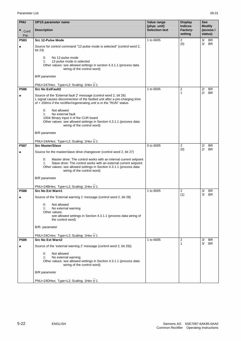
Parameter List 06.01
5-22 ENGLISH Siemens AG 6SE7087-6AK85-0AA0Common Rectifier Operating Instructions
PNU
* : Conf. Par.
OP1S parameter name
Description
Value range[phys. unit]Selection text
DisplayIndicesFactory-setting
SeeModify(access /status)
P583
*
Src 12-Pulse Mode
Source for control command "12-pulse mode is selected" (control word 2,bit 23)
0: No 12-pulse mode1: 12-pulse mode is selectedOther values: see allowed settings in section 4.3.1.1 (process data
wiring of the control word)
B/R parameter
PNU=247Hex; Type=L2; Scaling: 1Hex =∧ 1
1 to 6005 2(0)
3/ BR3/ BR
P586
*
Src No ExtFault2
Source of the 'External fault 2' message (control word 2, bit 26)L signal causes disconnection of the faulted unit after a pre-charging timeof + 200ms if the rectifier/regenerating unit is in the "RUN" status.
0: Not allowed1: No external fault1004: Binary input 4 of the CUR boardOther values: see allowed settings in Section 4.3.1.1 (process data
wiring of the control word)
B/R parameter
PNU=24AHex; Type=L2; Scaling: 1Hex =∧ 1
1 to 6005 21
2/ BR2/ BR
P587
*
Src Master/Slave
Source for the master/slave drive changeover (control word 2, bit 27)
0: Master drive: The control works with an internal current setpoint1: Slave drive: The control works with an external current setpointOther values: see allowed settings in Section 4.3.1.1 (process data
wiring of the control word)
B/R parameter
PNU=24BHex; Type=L2; Scaling: 1Hex =∧ 1
0 to 6005 2(0)
2/ BR2/ BR
P588
*
Src No Ext Warn1
Source of the 'External warning 1' message (control word 2, bit 28)
0: Not allowed1: No external warningOther values:
see allowed settings in Section 4.3.1.1 (process data wiring ofthe control word)
B/R- parameter
PNU=24CHex; Type=L2; Scaling: 1Hex =∧ 1
1 to 6005 2(1)
3/ BR3/ BR
P589
*
Src No Ext Warn2
Source of the 'external warning 2' message (control word 2, bit 29))
0: Not allowed1: No external warningOther values: see allowed settings in Section 4.3.1.1 (process data
wiring of the control word)
B/R parameter
PNU=24DHex; Type=L2; Scaling: 1Hex =∧ 1
1 to 6005 21
3/ BR3/ BR

06.01 Parameter List
Siemens AG 6SE7087-6AK85-0AA0 ENGLISH 5-23Common Rectifier Operating Instructions
PNU
* : Conf. Par.
OP1S parameter name
Description
Value range[phys. unit]Selection text
DisplayIndicesFactory-setting
SeeModify(access /status)
P590
*
Src Base/Reserve
Source of the 'Base / reserve settings' switching command (control word 2,bit 30)
0: Base setting1: Reserve setting1005: Binary input 5 of the CUR boardOther values: see allowed settings in Section 4.3.1.1 (process data
wiring of the control word)
No base/reserve changeover possible
PNU=24EHex; Type=L2; Scaling: 1Hex =∧ 1
0 to 6005 -1005
3/ BR3/ BR
P591
*
Src ContactorMsg
Source of the 'Main contactor energized' message(control word 2, bit 31)
0: Not allowed1: No main contactor checkback signal1001 to 1005: CUR terminals4101 to 4116: SCB-SCI1- terminals (serial I/O)4201 to 4216: SCB-SCI2- terminals (serial I/O)
For details see Section 4.3.1.1
Notes:If the function is active, pulses are released as soon as the message isavailable.No base / reserve settings possible
PNU=24FHex; Type=L2; Scaling: 1Hex =∧ 1
1 to 4216 -1
3/ BR3/ BR
r599 CW/SW 12-Pulse
Display of control/status word for 12-pulse mode, bit 0 to 15, see Section3.8.4.
67
1415
23
1011
01
89
45
1213
PNU=257Hex; Type=V2;Scaling: 1Hex =∧ 1
- 2/ BR
P600
*
Trg Bit Ready On
Destination of the status bit 'ready for turn ON' (status word 1, bit 0)Power is ON, the drive may be turned on.
Depending on the selected index all settings according to Section 4.3.1.2(process data wiring of the status word) may be selected.
i01: GG: selection of a base drive terminali02: SCI : selection of a SCI1/2 terminal
PNU=258Hex; Type=L2; Scaling: 1Hex =∧ 1
0 to 4212 20
3/ BR3/ BR
P601
*
Trg Bit Rdy Oper
Destination of the status bit 'Ready for operation' (status word 1, bit 1)
All the settings specified in Section 4.3.1.2 (process data wiring of thestatus word) are permissible, depending on the index selected
Parameter values, indices: as P600
PNU=259Hex; Type=L2; Scaling: 1Hex =∧ 1
0 to 4212 20
3/ BR3/ BR
P602
*
Trg Bit Operat
Destination of the status bit 'Run' (status word 1, bit 2)The unit is in operation.
Parameter values, indices: as P600
PNU=25AHex; Type=L2; Scaling: 1Hex =∧ 1
0 to 4212 20
2/ BR2/ BR

Parameter List 06.01
5-24 ENGLISH Siemens AG 6SE7087-6AK85-0AA0Common Rectifier Operating Instructions
PNU
* : Conf. Par.
OP1S parameter name
Description
Value range[phys. unit]Selection text
DisplayIndicesFactory-setting
SeeModify(access /status)
P603
*
Trg Bit Fault
Destination of the status bit 'Fault' (status word 1, bit 3)
Note:For issuing the fault message via a terminal the active status (bit has H-level) is inverted (broken wire proof).
Parameter values, indices: as P600
PNU=25BHex; Type=L2; Scaling: 1Hex =∧ 1
0 to 4212 2i001=1002i002=0
2/ BR2/ BR
P604
*
Trg Bit No OFF2
Destination of the status bit 'No OFF2 command' (status word 1, bit 4)
Parameter values, indices: as P600
PNU=25CHex; Type=L2; Scaling: 1Hex =∧ 1
0 to 4212 20
3/ BR3/ BR
P606
*
Trg BitONblocked
Destination of the status bit 'Turn-ON locked' (status word 1, bit 6)
Note:For issuing the message via a terminal the active status (bit has H-level) isinverted (broken wire proof).
Parameter values, indices: as P600
PNU=25EHex; Type=L2; Scaling: 1Hex =∧ 1
0 to 4212 20
3/ BR3/ BR
P607
*
Trg Bit Warning
Destination of the status bit 'Warning' (status word 1, bit 7)
Note:For issuing the message via a terminal the active status (bit has H-level) isinverted (broken wire proof).
Parameter values, indices: as P600
PNU=25FHex; Type=L2; Scaling: 1Hex =∧ 1
0 to 4212 2(0)
2/ BR2/ BR
P608
*
Trg Bit Deviat.
Destination wiring of the status bit "Ud set = Ud act“ (status word 1, bit 8) -cf. P517
Parameter values, indices: as P600
PNU=260Hex; Type=L2; Scaling: 1Hex =∧ 1
0 to 4212 20
3/ BR3/ BR
P610
*
Trg Regen Ready
Destination wiring of the status bit "Regenerating ready" (status word 1,Bit 10)
Parameter values, indices: as P600
PNU=260Hex; Type=L2; Scaling: 1Hex =∧ 1
0 to 4212 20
3/ BR3/ BR
P611
*
Trg Low Voltage
Destination of the status bit 'Undervoltage' (status word 1, bit 11)
Note:For issuing the message via a terminal the active status (bit has H-level) isinverted (broken wire proof).
Parameter values, indices: as P600
PNU=263Hex; Type=L2; Scaling: 1Hex =∧ 1
0 to 4212 20
3/ BR3/ BR

06.01 Parameter List
Siemens AG 6SE7087-6AK85-0AA0 ENGLISH 5-25Common Rectifier Operating Instructions
PNU
* : Conf. Par.
OP1S parameter name
Description
Value range[phys. unit]Selection text
DisplayIndicesFactory-setting
SeeModify(access /status)
P612
*
Trg Bit Contact
Destination of the status bit 'Energize main contactor' (status word 1, bit 12)H level: energize contactor!
Important: Relay X9-4/5, whose function cannot be programmed, isprovided for controlling the main contactor.
Parameter values, indices: as P600
PNU=264Hex; Type=L2; Scaling: 1Hex =∧ 1
0 to 4212 20
3/ BR3/ BR
P613
*
Trg DC V reduced
Destination wiring for the status bit "Ud reduced“(status word 1, bit 13)
Parameter values, indices: as P600
PNU=265Hex; Type=L2; Scaling: 1Hex =∧ 1
0 to 4212 20
3/ ABR3/ ABR
P614
***
Trg Motor/Regen
Destination wiring for the status bit "Regenerative/motoring mode" (statusword 1, bit 14)
Parameter values, Indices: as P600
PNU=266Hex; Type=L2; Scaling: 1Hex =∧ 1
0 to 4212 20
3/ BR3/ BR
P618
*
Trg Current Lim.
Destination wiring of the status bit "Current limit active"(status word 2, bit 18)
Note:For issuing the message via a terminal the active status (bit has H-level) isinverted (broken-wire proof).
Parameter values, indices: as P600
PNU=26AHex; Type=L2; Scaling: 1Hex =∧ 1
0 to 4212 20
3/ BR3/ BR
P619
*
Trg Bit Ext Flt1
Destination of the status bit 'External fault 1' (status word 2, bit 19)
Note:For issuing the message via a terminal the active status (bit has H-level) isinverted (broken wire proof).
Parameter values, indices: as P600
PNU=26BHex; Type=L2; Scaling: 1Hex =∧ 1
0 to 4212 20
3/ BR3/ BR
P620
*
Trg Bit Ext Flt2
Destination of the status bit 'External fault 2'(status word 2, bit 20)Note:For issuing the message via a terminal the active status (bit has H-level) isinverted (broken wire proof).If an ON command is active, L-level causes fault trip after 200 msec.
Parameter values, indices: as P600
PNU=26CHex; Type=L2; Scaling: 1Hex =∧ 1
0 to 4212 20
3/ BR3/ BR

Parameter List 06.01
5-26 ENGLISH Siemens AG 6SE7087-6AK85-0AA0Common Rectifier Operating Instructions
PNU
* : Conf. Par.
OP1S parameter name
Description
Value range[phys. unit]Selection text
DisplayIndicesFactory-setting
SeeModify(access /status)
P621
*
Trg Bit ExtWarn
Destination of the status bit 'External warning'(status word 2, bit 21)
Note:For issuing the message via a terminal the active status (bit has H-level) isinverted (broken wire proof).
Parameter values, indices: as P600
PNU=26DHex; Type=L2; Scaling: 1Hex =∧ 1
0 to 4212 20
3/ BR3/ BR
P622
*
Trg Bit i2t Inv
Destination of the status bit 'Warning unit overload'(status word 2, bit 22);
Note:For issuing the message via a terminal the active status (bit has H-level) isinverted (broken wire proof).
Parameter values, indices: as P600
PNU=26EHex; Type=L2; Scaling: 1Hex =∧ 1
0 to 4212 20
3/ BR3/ BR
P623
*
Trg BitFltTmpInv
Destination of the status bit 'Fault unit overtemperature'(status word 2, bit 23
Note:For issuing the message via a terminal the active status (bit has H-level) isinverted (broken wire proof).
Parameter values, Indices: as for P600
PNU=26FHex; Type=L2; Scaling: 1Hex =∧ 1
0 to 4212 20
3/ BR3/ BR
P624
*
Trg BitWarTmpInv
Destination of the status bit 'Warning unit overtemperature'(status word 2, bit 24
Note:For issuing the message via a terminal the active status (bit has H-level) isinverted (broken wire proof).
Parameter values, indices: as P600
PNU=270Hex; Type=L2; Scaling: 1Hex =∧ 1
0 to 4212 20
3/ BR3/ BR
P631
*
Trg Bit Charging
Destination of the status bit 'Charging active' (status word 2, bit 31)
Note:For issuing the message via a terminal the active status (bit has H-level) isinverted (broken wire proof).
Parameter values, indices: as P600
PNU=277Hex; Type=L2; Scaling: 1Hex =∧ 1
0 to 4212 20
3/ BR3/ BR

06.01 Parameter List
Siemens AG 6SE7087-6AK85-0AA0 ENGLISH 5-27Common Rectifier Operating Instructions
PNU
* : Conf. Par.
OP1S parameter name
Description
Value range[phys. unit]Selection text
DisplayIndicesFactory-setting
SeeModify(access /status)
5.11 Analog input/output
P655 CUR AnaOutActVal
Number of the parameters whose value is to be output at the analog outputof the CUR, (terminal X102-14).
PNU=28FHex; Type=O2; Scaling: 1Hex =∧ 1
0 to 999 -37
2/ BR2/ BR
P656 CUR AnaOut Gain
Gain for the analog output of the CUR (terminal X102-14)
P656 = desired analog output voltage at PWE=100%, if offset=0
The output voltage is calculated with the following formula:U(out)= [(PWE/100%) * P656] + P657
PNU=290Hex; Type=I2; Scaling: 1Hex =∧ 0.01 V
±320,00[V]
-10.00
2/ BR2/ BR
P657 CUR AnaOutOffset
Offset for the analog output on the CUR (terminal X102-14)The analog output can represent voltages of -10V to +10V.
PNU=291Hex; Type=I2; Scaling: 1Hex =∧ 0.01 V
-100.00 to 100.00[V]
-0.00
2/ BR2/ BR
P658
*
AnaOut Conf Curr
Configuration of terminal X102-16 (actual current display)0 Output with correct sign
(positive voltage: motoring current)(negative voltage: regenerative current)
1 Output absolute value (positive voltage only)
2 Signed output, inverted(positive voltage: regenerative current)(negative voltage: motoring current)
3 Output of absolute value, inverted (negative voltage only)
PNU=292Hex; Type=O2; Scaling: 1Hex =∧ 1
0 to 3
signed
absoluteValinverted
inv. absVal
-0
2/ BR2/ BR
P660 SCI AnalogInConf
Configuration of the SCI analog inputs; defines the kind of the input signals
Parameter values Terminals TerminalsX428/3, 6, 9 X428/5, 8, 11
0: -10 V ... + 10 V - 20 mA ... + 20 mA1: 0 V ... + 10 V 0 mA ... + 20 mA2: 4 mA ... + 20 mA
Notes:Only one signal can be wired per input; alternatively voltage or currentsignals can be evaluated.Voltage and current signals must be connected to different terminals.Settings 1 and 2 only allow unipolar signals, i. e. the internal process dataare also unipolar.At setting 2 an input current < 2 mA causes a fault trip (broken wire proof)The offset scaling of the analog inputs is done via P662.
i001: Sl11 Slave 1, analog input 1i002: Sl12 Slave 1, analog input 2i003: Sl13 Slave 1, analog input 3i004: Sl21 Slave 2, analog input 1i005: Sl22 Slave 2, analog input 2i006: Sl23 Slave 2, analog input 3
Condition:The related SCB board must be reported via P090 and P091, respectively
PNU=294Hex; Type=O2; Scaling: 1Hex =∧ 1
0 to 2 60
3/ BR3/ BR
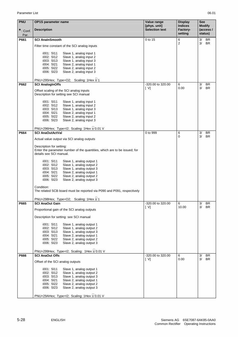
Parameter List 06.01
5-28 ENGLISH Siemens AG 6SE7087-6AK85-0AA0Common Rectifier Operating Instructions
PNU
* : Conf. Par.
OP1S parameter name
Description
Value range[phys. unit]Selection text
DisplayIndicesFactory-setting
SeeModify(access /status)
P661 SCI AnaInSmooth
Filter time constant of the SCI analog inputs
i001: Sl11 Slave 1, analog input 1i002: Sl12 Slave 1, analog input 2i003: Sl13 Slave 1, analog input 3i004: Sl21 Slave 2, analog input 1i005: Sl22 Slave 2, analog input 2i006: Sl23 Slave 2, analog input 3
PNU=295Hex; Type=O2; Scaling: 1Hex =∧ 1
0 to 15 62
3/ BR3/ BR
P662 SCI AnalogInOffs
Offset scaling of the SCI analog inputsDescription for setting see SCI manual
i001: Sl11 Slave 1, analog input 1i002: Sl12 Slave 1, analog input 2i003: Sl13 Slave 1, analog input 3i004: Sl21 Slave 2, analog input 1i005: Sl22 Slave 2, analog input 2i006: Sl23 Slave 2, analog input 3
PNU=296Hex; Type=I2; Scaling: 1Hex =∧ 0.01 V
-320.00 to 320.00[V]
60.00
3/ BR3/ BR
P664 SCI AnaOutActVal
Actual value output via SCI analog outputs
Description for setting:Enter the parameter number of the quantities, which are to be issued; fordetails see SCI manual.
i001: Sl11 Slave 1, analog output 1i002: Sl12 Slave 1, analog output 2i003: Sl13 Slave 1, analog output 3i004: Sl21 Slave 2, analog output 1i005: Sl22 Slave 2, analog output 2i006: Sl23 Slave 2, analog output 3
Condition:The related SCB board must be reported via P090 and P091, respectively
PNU=298Hex; Type=O2; Scaling: 1Hex =∧ 1
0 to 999 60
3/ BR3/ BR
P665 SCI AnaOut Gain
Proportional gain of the SCI analog outputs
Description for setting: see SCI manual
i001: Sl11 Slave 1, analog output 1i002: Sl12 Slave 1, analog output 2i003: Sl13 Slave 1, analog output 3i004: Sl21 Slave 2, analog output 1i005: Sl22 Slave 2, analog output 2i006: Sl23 Slave 2, analog output 3
PNU=299Hex; Type=I2; Scaling: 1Hex =∧ 0.01 V
-320.00 to 320.00[V]
610.00
3/ BR3/ BR
P666 SCI AnaOut Offs
Offset of the SCI analog outputs
i001: Sl11 Slave 1, analog output 1i002: Sl12 Slave 1, analog output 2i003: Sl13 Slave 1, analog output 3i004: Sl21 Slave 2, analog output 1i005: Sl22 Slave 2, analog output 2i006: Sl23 Slave 2, analog output 3
PNU=29AHex; Type=I2; Scaling: 1Hex =∧ 0.01 V
-320.00 to 320.00[V]
60.00
3/ BR3/ BR

06.01 Parameter List
Siemens AG 6SE7087-6AK85-0AA0 ENGLISH 5-29Common Rectifier Operating Instructions
PNU
* : Conf. Par.
OP1S parameter name
Description
Value range[phys. unit]Selection text
DisplayIndicesFactory-setting
SeeModify(access /status)
5.12 Communications
P680
*
Scom1 Act Value
Process data assignment for actual-value output over serial interface SST1.Defines the parameter positions in the telegram.
Notes:Word 1 should be assigned status word 1 (r552=r968).
The length (number of words) of the process data part in the telegram is setwith P686, Index i001.
i001=Word 01 of the (process data part of the) telegrami002=Word 02 of the (process data part of the) telegram...i016=Word 16 of the (process data part of the) telegram
PNU=2A8Hex; Type=O2; Scaling: 1Hex =∧ 1
0 to 999 16i001=968i002=0. . .i016=0
3/ BR3/ B
P681
*
Scom2 Act Value
Selection of the process data to be transmitted over serial interface SST2(actual values) with peer-to-peer protocol selected (P688=1).Defines the parameter positions in the telegram.
Notes:The length (number of words) of the process data part in the peer-to-peertelegram is set with P686, Index i003.
i001=Word 1 of the (process data part of the) telegrami002=Word 2 of the (process data part of the) telegram...i005=Word 5 of the (process data part of the) telegram
PNU=2A9Hex; Type=O2; Scaling: 1Hex =∧ 1
0 to 999 5i001=599i002=34i003=0i004=0i005=0
3/ BR3/ B
P682
*
SCB Protocol
SCB can be operated asmaster for the SCI boards or asserial communications board
(see SCB manual).
0 = SCI-Module: Master for SCI boards1 = 4 wire USS2 = 2 wire USS3 = Peer to Peer4 = Option-1: not used5 = Option-2; not used
Condition:SCB board must be reported via P090 and 0P91, respectively
PNU=2AAHex; Type=O2; Scaling: 1Hex =∧ 1
0 to 5
SCI-Module4 wire USS2 wire USSPeer 2 PeerOption 1Option 2
-0
3/ HBR3/ H
P683
*
SCom/SCB BusAddr
Bus address of the serial communication interfaces
i001 = SST1: bus address of serial comm. interface 1 (CUR)i002 = SCB: SCB baud rate, if P682=1, 2
PNU=2ABHex; Type=O2; Scaling: 1Hex =∧ 1
0 to 30 20
3/ BR3/ B

Parameter List 06.01
5-30 ENGLISH Siemens AG 6SE7087-6AK85-0AA0Common Rectifier Operating Instructions
PNU
* : Conf. Par.
OP1S parameter name
Description
Value range[phys. unit]Selection text
DisplayIndicesFactory-setting
SeeModify(access /status)
P684
*
SCom/SCB Baud
Serial interfaces baud rate
1 300 Baud2 600 Baud3 1200 Baud4 2400 Baud5 4800 Baud6 9600 Baud7 19200 Baud8 38400 Baud9 57650 Baud10 76800 Baud11 93750 Baud12 115200 Baud13 187500 Baud
i001 = SST1: serial comm. interface 1 (CUR)i002 = SCB: SCB, if P682=1, 2, 3i003 = SST2: serial comm. interface 2 (CUR with PTP1 option)
PNU=2ACHex; Type=O2; Scaling: 1Hex =∧ 1
1 to 813
300 Bd600 Bd1200 Bd2400 Bd4800 Bd9600 Bd19200 Bd38400 Bd57650 Bd76800 Bd93750 Bd115200 Bd187500 Bd
2i001=6i002=6i003=13
3/ BR3/ B
P685
*
SCom/SCB #PKWDat
Number of words (16 bit) of the parameter data part in the net data block ofthe telegram.
0: No parameter data part in the telegram3, 4 Parameter data part is 3 (parameter identifier, Ind, parameter
value), 4 words long127 Variable parameter data length for the transfer of parameter
description and texts
i001 = SST1: serial comm. interface 1 (CUR)i002 = SCB: SCB, if P682=1, 2
PNU=2ADHex; Type=O2; Scaling: 1Hex =∧ 1
0 to 127 2i001=127i002=127
3/ BR3/ B
P686
*
SCom/SCB # PrDat
Number of words (16 bits) of the process data part in the net data block ofthe telegram.
i001 = SST1: serial comm. interface 1 (CUR)i002 = SCB: SCB, if P682=1, 2, 3
PWE=0 means that no process data are expected in the USS protocol andthat none are sent.
i003 = SST2: serial comm. interface 2 (CUR with PTP1 option), ifPeer-to-Peer protocol is selected (P688=1), from 1 to 5 netdata words can be sent.
PNU=2AEHex; Type=O2; Scaling: 1Hex =∧ 1
0 to 16 32
3/ BR3/ B

06.01 Parameter List
Siemens AG 6SE7087-6AK85-0AA0 ENGLISH 5-31Common Rectifier Operating Instructions
PNU
* : Conf. Par.
OP1S parameter name
Description
Value range[phys. unit]Selection text
DisplayIndicesFactory-setting
SeeModify(access /status)
P687
*
SCom/SCB TlgOFF
Telegram OFF time of CUR and SCBIf no correct telegram is received within the parameterized time a fault tripis set.
Description for setting:Value 0: No monitoring, no fault trip; must be parameterized for sporadic(acyclic) telegrams, e. g. operator panel OP at serial comm. interface 1.
i001 = SST1: serial comm. interface 1 (CUR)i002 = SCB: SCB, if P682=1, 2, 3
i003 = SST2: serial comm. interface 2 (CUR with PTP1 option), ifPeer-to-Peer protocol is selected (P688=1).With active Peer-To-Peer protocol (P688 = 1) and telegramfailure time P687.i003 ≠ 0, the unit remains in operating stateo008 until telegram traffic is correct (see P688).With P687.i003 = 0 AND P681.i001 = 599 in the case oftelegram failure, bits 3 and 6 of the first SST2 Peer-to-Peerreceive data (the control/status word sent from the partner unitin 12-pulse mode) are set to 0.
PNU=2AFHex; Type=O2; Scaling: 1Hex =∧ 1ms
0 to 6500[ms]
3i001=0i002=0i003=1
2/ BR2/ BR
P688
*
SST2 Protocol
Selection of the protocol for SST2 (serial interface 2 (CUR with PTP1option))
0 Interface is provided for factory-internal diagnostics purposes (7data bits + 1 parity bit, even parity,1 stop bit)
1 Peer-to-Peer protocol(8 data bits + 1 parity bit, even parity,1 stop bit)With active Peer-To-Peer protocol (P688 = 1) and telegramfailure time P687.i003 ≠ 0, the unit remains in operating stateo008 until telegram traffic is correct.
PNU=2B0Hex; Typ=O2; Normierung: 1Hex =∧ 1
0 to 1
factory-internalPeer to Peer
-0
3/ BR3/ B
P689 SCB Peer2PeerExt
Immediate transfer on of data received via the peer to peer protocol ofSCB.Mark of these words of the received peer to peer telegram which are to betransferred on immediately.
0: No immediate transfer (only to CUR)1: Immediate transfer (and passing to CUR)
i001 = W01: Word 01 of the (process data part of the) telegrami002 = W02: Word 02 of the (process data part of the) telegram
. . . . .i005 = W05: Word 05 of the (process data part of the) telegram
Condition: P682 = 3 (peer to peer protocol)
PNU=2B1Hex; Type=O2; Scaling: 1Hex =∧ 1
0 to 1
CUR onlyTransfer
50
3/ BR3/ BR
P690
*
SCB Act Values
Actual value output via the serial communications interface of the SCBboard.Defines, which parameter is to be transferred at which telegram address.
Notes:Word 1 should be set for status word 1 (r552=r968)
The length (number of words) of the process data part of the telegram is setwith P686, Index 02
i001 Word 01 of the (process data part of the) telegrami002 Word 02 of the (process data part of the) telegram...i016 Word16 of the (process data part of the) telegram
PNU=2B2Hex; Type=O2; Scaling: 1Hex =∧ 1
0 to 999 16i001=968i002=0. . .i016=0
3/ BR3/ B
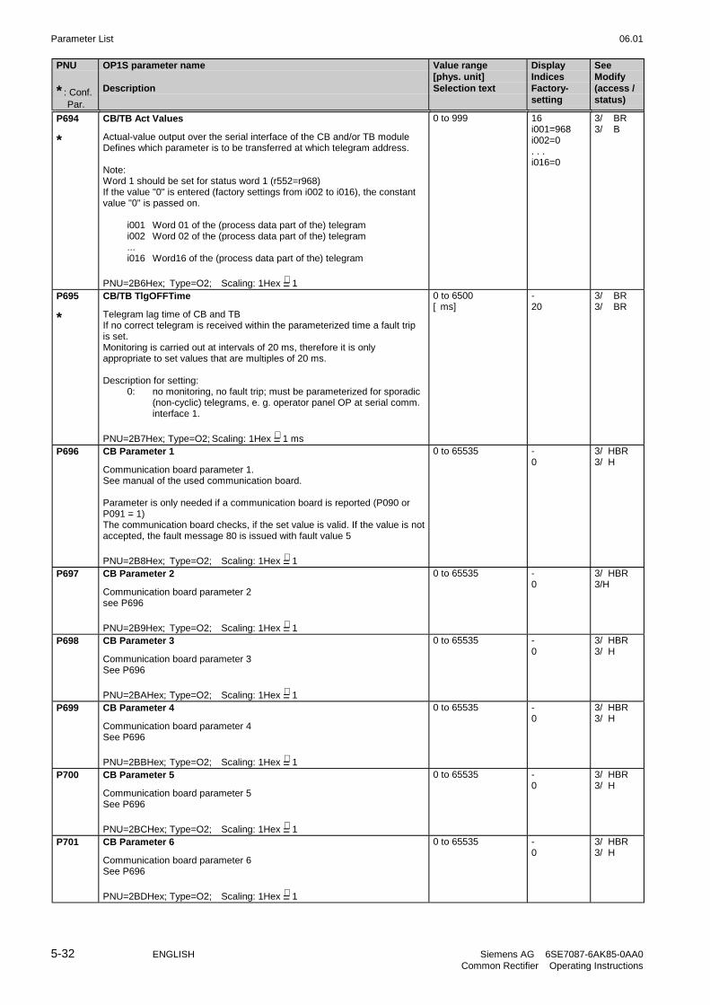
Parameter List 06.01
5-32 ENGLISH Siemens AG 6SE7087-6AK85-0AA0Common Rectifier Operating Instructions
PNU
* : Conf. Par.
OP1S parameter name
Description
Value range[phys. unit]Selection text
DisplayIndicesFactory-setting
SeeModify(access /status)
P694
*
CB/TB Act Values
Actual-value output over the serial interface of the CB and/or TB moduleDefines which parameter is to be transferred at which telegram address.
Note:Word 1 should be set for status word 1 (r552=r968)If the value "0" is entered (factory settings from i002 to i016), the constantvalue "0" is passed on.
i001 Word 01 of the (process data part of the) telegrami002 Word 02 of the (process data part of the) telegram...i016 Word16 of the (process data part of the) telegram
PNU=2B6Hex; Type=O2; Scaling: 1Hex =∧ 1
0 to 999 16i001=968i002=0. . .i016=0
3/ BR3/ B
P695
*
CB/TB TlgOFFTime
Telegram lag time of CB and TBIf no correct telegram is received within the parameterized time a fault tripis set.Monitoring is carried out at intervals of 20 ms, therefore it is onlyappropriate to set values that are multiples of 20 ms.
Description for setting:0: no monitoring, no fault trip; must be parameterized for sporadic
(non-cyclic) telegrams, e. g. operator panel OP at serial comm.interface 1.
PNU=2B7Hex; Type=O2; Scaling: 1Hex =∧ 1 ms
0 to 6500[ms]
-20
3/ BR3/ BR
P696 CB Parameter 1
Communication board parameter 1.See manual of the used communication board.
Parameter is only needed if a communication board is reported (P090 orP091 = 1)The communication board checks, if the set value is valid. If the value is notaccepted, the fault message 80 is issued with fault value 5
PNU=2B8Hex; Type=O2; Scaling: 1Hex =∧ 1
0 to 65535 -0
3/ HBR3/ H
P697 CB Parameter 2
Communication board parameter 2see P696
PNU=2B9Hex; Type=O2; Scaling: 1Hex =∧ 1
0 to 65535 -0
3/ HBR3/H
P698 CB Parameter 3
Communication board parameter 3See P696
PNU=2BAHex; Type=O2; Scaling: 1Hex =∧ 1
0 to 65535 -0
3/ HBR3/ H
P699 CB Parameter 4
Communication board parameter 4See P696
PNU=2BBHex; Type=O2; Scaling: 1Hex =∧ 1
0 to 65535 -0
3/ HBR3/ H
P700 CB Parameter 5
Communication board parameter 5See P696
PNU=2BCHex; Type=O2; Scaling: 1Hex =∧ 1
0 to 65535 -0
3/ HBR3/ H
P701 CB Parameter 6
Communication board parameter 6See P696
PNU=2BDHex; Type=O2; Scaling: 1Hex =∧ 1
0 to 65535 -0
3/ HBR3/ H

06.01 Parameter List
Siemens AG 6SE7087-6AK85-0AA0 ENGLISH 5-33Common Rectifier Operating Instructions
PNU
* : Conf. Par.
OP1S parameter name
Description
Value range[phys. unit]Selection text
DisplayIndicesFactory-setting
SeeModify(access /status)
P702 CB Parameter 7
Communication board parameter 7See P696
PNU=2BEHex; Type=O2; Scaling: 1Hex =∧ 1
0 to 65535 -0
3/ HBR3/ H
P703 CB Parameter 8
Communication board parameter 8See P696
PNU=2BFHex; Type=O2; Scaling: 1Hex =∧ 1
0 to 65535 -0
3/ HBR3/ H
P704 CB Parameter 9
Communication Board Parameter 9See P696
PNU=2C0Hex; Type=O2; Scaling: 1Hex =∧ 1
0 to 65535 -0
3/ HBR3/ H
P705 CB Parameter 10
Communication board parameter 10See P696
PNU=2C1Hex; Type=O2; Scaling: 1Hex =∧ 1
0 to 65535 -0
3/ HBR3/ H
P706 CB Parameter 11
Communication board parameter 11
See P696
PNU=2C2Hex; Type=L2; Scaling: 1Hex =∧ 1
0 50
3/ HBR3/ H

Parameter List 06.01
5-34 ENGLISH Siemens AG 6SE7087-6AK85-0AA0Common Rectifier Operating Instructions
PNU
* : Conf. Par.
OP1S parameter name
Description
Value range[phys. unit]Selection text
DisplayIndicesFactory-setting
SeeModify(access /status)
5.13 Diagnostics
r720 SW Version
Software version of the PCBs in positions 1, 2 and 3 of the electronic box.
Indices:i001: Pos1: Software version of the PCB in position 1i002: Pos2: Software version of the PCB in position 2i003: Pos3: Software version of the PCB in position 3
PNU=2D0Hex; Type=O2; Scaling: 1Hex =∧ 0.1
3
Pos1Pos2Pos3
3/U BR
r721 SW Generat. Date
Software generation date of the CUR board.
Indices: i001= Yeari002= Monthi003= Day
PNU=2D1Hex; Type=O2; Scaling: 1Hex =∧ 1
YearMonDay
3 3/U BR
r722 SW ID
Extended software version ID of the modules in slots 1, 2 and 3 of theelectronic box for internal purposes.
Indices:i001: SPL1: Software code of the PCB in position 1i002: SPL2: Software code of the PCB in position 2i003: SPL3: Software code of the PCB in position 3
PNU=2D2Hex; Type=O2; Scaling: 1Hex =∧ 0.1
3 3/U BR
r723 PCB Code
Identification code of the PCBs in positions 1, 2 and 3 of the electronic box
Indices:i001: SPL1: PCB code of the PCB in position 1i002: SPL2: PCB code of the PCB in position 2i003: SPL3: PCB code of the PCB in position 3
PCB codes:CUR: 105CB: 140 - 149TB: 130 - 139SCB: 120 - 129
PNU=2D3Hex; Type=O2; Scaling: 1Hex =∧ 1
3 3/U BR
r725 HeadroomCalcTime
Headroom of the CPU on the CUR module.
PNU=2D5Hex; Type=O2; Scaling: 1Hex =∧ 1 % PZD gr.: 1
Analog output: 100% =∧ 100% computer time free
0 to 100%[%]
--
3/ BR

06.01 Parameter List
Siemens AG 6SE7087-6AK85-0AA0 ENGLISH 5-35Common Rectifier Operating Instructions
PNU
* : Conf. Par.
OP1S parameter name
Description
Value range[phys. unit]Selection text
DisplayIndicesFactory-setting
SeeModify(access /status)
r730 SCB Diagnostics
SCB diagnosticsAll values in HEX displayIf a quantity is represented, overflow takes place at FF Hex.The meaning of several Indices depends of the selected SCB protocol(P682).
i001: flTC Number of error-free telegramsi002: Terr Number of error telegramsi003: Ferr Number of byte frame-errorsi004: Orun Number of overrun errorsi005: Prty Parity errori006: STX STX errori007: ETX ETX errori008: BCC Block check errori009: L/KL USS/Peer to Peer: incorrect telegram length
SCI modules: required maximum number of terminalsaccording to process data wiring (P554 to P631).
i010: T/An USS: TimeoutSCI Modules: required analog inputs / outputsaccording to process data wiring of the setpointchannel and actual value output via SCI (P664) .
i011: BCd0 PCB code word 0i012: BCd1 PCB code word 1i013: Warn SCB-DPR- warning wordi014: Sl1? Information, if slave 1 needed and if yes, which type.
0: no slave needed1: SCI12: SCI2
i015: Sl2? Information, if slave 2 needed and if yes, which type.0: no slave needed1: SCI12: SCI2
i016: IniF: with 'SCI modules': initialization fault
PNU=2DAHex; Type=L2; Scaling: 1Hex =∧ 1
16 3/ HBR
r731 CB/TB Diagnostics
For detailed information see manuals of the used communication boards(CB) or technology boards (TB).
PNU=2DBHex; Type=L2; Scaling: 1Hex =∧ 1
32 3/ HBR
r748 Fault Time
The instants at which faults occur (reading of the hours counter r013 at theinstant the fault occurs)
See parameter r947 for details
Trip description by: r947 Fault numberr949 Fault valuer951 List of fault textsP952 Number of faults
PNU=2ECHex; Type=O2; Scaling: 1Hex =∧ 1
24 2/ BR

Parameter List 06.01
5-36 ENGLISH Siemens AG 6SE7087-6AK85-0AA0Common Rectifier Operating Instructions
PNU
* : Conf. Par.
OP1S parameter name
Description
Value range[phys. unit]Selection text
DisplayIndicesFactory-setting
SeeModify(access /status)
5.14 Modulator
P773 Deadband Convert
The reversing threshold of the auto-reversing module (in rectifier direction)
If the (signed) setpoint of the DC link current (output of the DC link voltagecontroller on the output side of the limiting module) exceeds the value of +0.05% set with this parameter, the firing pulses of the rectifier bridge areenabled. These pulses are inhibited if the setpoint of the DC link currentdrops below the value set here.
RDS parameter
PNU=305Hex; Type=O2; Scaling: 1Hex =∧ 0.01 %
0.01 to 100.00[%]
40.01
3/ BR3/ BR
P774
**
Deadband Invert
The reversing threshold of the auto-reversing module (in regeneratingdirection)If the (signed) setpoint of the DC link current (output of the DC link voltagecontroller on the output side of the limiting module) exceeds the value of -0.05% set with this parameter, the firing pulses of the rectifier bridge areenabled. These pulses are inhibited if the setpoint of the DC link currentdrops below the value set here..
RDS parameter
PNU=306Hex; Type=O2; Scaling: 1Hex =∧ 0.01
-100.00 to -0.01[%]
4-3.00
3/ BR3/ BR
P775 Min Gating Angle
Alpha G limit (rectifier stability limit)
RDS parameter
PNU=307Hex; Type=O2; Scaling: 1Hex =∧ 1 °el
0 to 120[°el]
40
3/ BR3/ BR
P776 Max Gating Angle
Alpha W limit (inverter stability limit)
RDS parameter
PNU=308Hex; Type=O2; Scaling: 1Hex =∧ 1 °el
120 to 165[°el]
4150
3/ BR3/ B
P777 Max Gating Angle Ramp
Transition ramp of the alpha W limit from pulsating to continuous DC (forcurrents < pulsating threshold, the control angle is limited to 165°, forcurrents > (pulsating threshold+P777) to P776 with linear interpolationinbetween)
RDS parameter
PNU=309Hex; Type=O2; Scaling: 1Hex =∧ 1 %
0.00 to 100.00[%] of P075
420.00
3/ BR3/ BR

06.01 Parameter List
Siemens AG 6SE7087-6AK85-0AA0 ENGLISH 5-37Common Rectifier Operating Instructions
PNU
* : Conf. Par.
OP1S parameter name
Description
Value range[phys. unit]Selection text
DisplayIndicesFactory-setting
SeeModify(access /status)
5.15 Factory parameters
P785
*
I2t Control Word
Control word for the i2t power section
0 Response of the i2t monitor for the power section (i.e. 100% of
the i2t value has been reached) results in an automatic
reduction of the limit for the current setpoint to the rated DCcurrent (in infeed direction or at 92% of the rated direct currentin regenerative feedback direction) until the absolute value ofthe current setpoint has dropped below the rated DC currentbefore its limit (or 92% of that in regenerative feedbackdirection) and the calculated equivalent junction temperaturerise is again below the unit-specific response threshold. Thecurrent setpoint limit is then raised again.
1 Response of the i2t monitor for the power section (i.e. 100% of
the i2t value has been reached) results in fault F022 and
disconnection.
PNU=311Hex; Type=O2; Scaling: 1Hex =∧ 1
0 to 1 -1
3/ HBR3/ B
P793 Line Voltage Delay
Stabilizing time for the line voltage
If the "Switch-on" command is given, the unit waits in status o010 forvoltage to be applied to the power section. The line voltage is not assumedto be applied to the power terminals until amplitude, frequency and phasesymmetry lie within the permissible tolerance range for longer than the timeset with this parameter. The parameter applies to both the rectifier andregenerative power terminals.
PNU=319Hex; Type=O2; Scaling: 1Hex =∧ 0.01 s
0.01 to 1.00[s]
-0.03
3/ BR3/ BR
P799 Special Access
Parameter for special access
PNU=31FHex; Type=O2; Scaling: 1Hex =∧ 1
0 to 65535 -0
3/U BR3/ BR
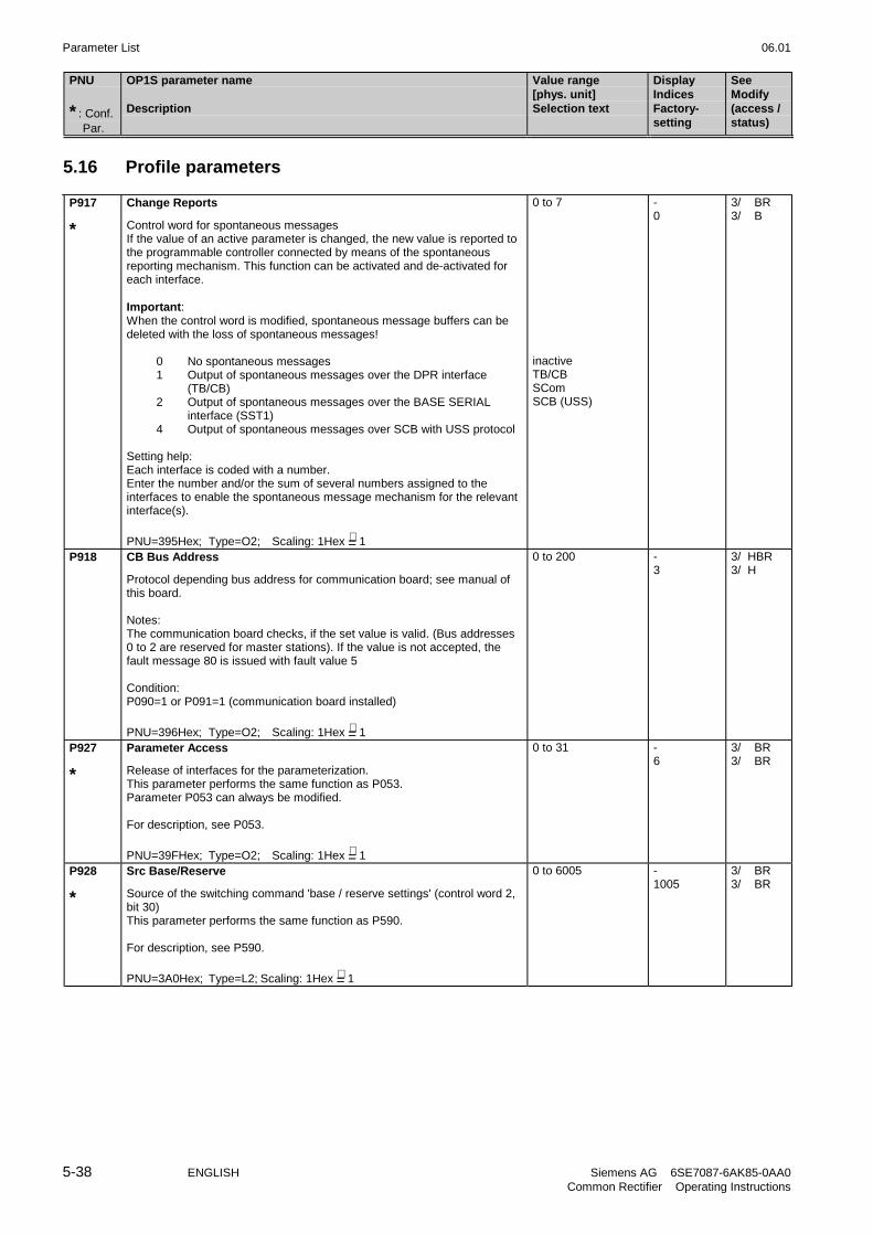
Parameter List 06.01
5-38 ENGLISH Siemens AG 6SE7087-6AK85-0AA0Common Rectifier Operating Instructions
PNU
* : Conf. Par.
OP1S parameter name
Description
Value range[phys. unit]Selection text
DisplayIndicesFactory-setting
SeeModify(access /status)
5.16 Profile parameters
P917
*
Change Reports
Control word for spontaneous messagesIf the value of an active parameter is changed, the new value is reported tothe programmable controller connected by means of the spontaneousreporting mechanism. This function can be activated and de-activated foreach interface.
Important:When the control word is modified, spontaneous message buffers can bedeleted with the loss of spontaneous messages!
0 No spontaneous messages1 Output of spontaneous messages over the DPR interface
(TB/CB)2 Output of spontaneous messages over the BASE SERIAL
interface (SST1)4 Output of spontaneous messages over SCB with USS protocol
Setting help:Each interface is coded with a number.Enter the number and/or the sum of several numbers assigned to theinterfaces to enable the spontaneous message mechanism for the relevantinterface(s).
PNU=395Hex; Type=O2; Scaling: 1Hex =∧ 1
0 to 7
inactiveTB/CBSComSCB (USS)
-0
3/ BR3/ B
P918 CB Bus Address
Protocol depending bus address for communication board; see manual ofthis board.
Notes:The communication board checks, if the set value is valid. (Bus addresses0 to 2 are reserved for master stations). If the value is not accepted, thefault message 80 is issued with fault value 5
Condition:P090=1 or P091=1 (communication board installed)
PNU=396Hex; Type=O2; Scaling: 1Hex =∧ 1
0 to 200 -3
3/ HBR3/ H
P927
*
Parameter Access
Release of interfaces for the parameterization.This parameter performs the same function as P053.Parameter P053 can always be modified.
For description, see P053.
PNU=39FHex; Type=O2; Scaling: 1Hex =∧ 1
0 to 31 -6
3/ BR3/ BR
P928
*
Src Base/Reserve
Source of the switching command 'base / reserve settings' (control word 2,bit 30)This parameter performs the same function as P590.
For description, see P590.
PNU=3A0Hex; Type=L2; Scaling: 1Hex =∧ 1
0 to 6005 -1005
3/ BR3/ BR

06.01 Parameter List
Siemens AG 6SE7087-6AK85-0AA0 ENGLISH 5-39Common Rectifier Operating Instructions
PNU
* : Conf. Par.
OP1S parameter name
Description
Value range[phys. unit]Selection text
DisplayIndicesFactory-setting
SeeModify(access /status)
r947 Fault Memory
Display of the faults which have occurred at the last trips. Each faultnumber has a fault value and a fault time assigned to it (see Chapter 7 fordetails of fault numbers and fault values). The relationship between theresponsible parameters is shown in the diagram below.
The fault numbers for the last (8 max.) faults are stored under the indices ofparameter r947. The fault number for the current (not yet reset) trip isindicated by r947.001, the fault number for the last reset fault is indicatedby index 9, the fault number of the last-but-one reset fault is indicated byindex 17, etc. The entry "0" here means that no previous fault has occurred.In contrast to the converter (SIMOVERT Master Drive FC, VC, SC), in thecase of the rectifier/regenerating unit only one fault can occur for each trip,therefore the only significant indices are 1, 9, 17, 25, 33, 41, 49 and 57.
A fault value in the appropriate index of parameter r949 is assigned to everyfault number. This provides more detailed information on the type of fault.
Apart from this, for each trip, the fault time which is the actual value of theoperating hours counter (r013) is stored in parameter r748. The data for thecurrent (not yet reset) trip is present as "day", "hours" and "seconds" inindices 1 to 3. The data for the already reset, previous trips is present ingroups of 3 elements on the following indices.
0
0
0
0
0
0
0
0
0
0
0
0
0
0
. . .
0
0
0
0
0
0
0
0
0
0
0
0
0
0
. . .
Index 1
Index 9
Index 17
Current
1st acknowl.
Current
r947Fault number
r949Fault value
r049Fault time [h]
Index 1
Index 2
Index 3
Index 4
Index 5
Index 6
Index 7
Index 8
Current
1st acknowl.
2nd acknowl. 2nd acknowl.
1st acknowl.
2nd acknowl.
3rd acknowl.
4th acknowl.
5th acknowl.
6th acknowl.
7th acknowl.
Plain text describing the fault numbers is available under the correspondingindex of parameter r951.
If the electronics supply voltage fails, all fault numbers are saved, but onlythose fault values and fault times relating to the last trip are stored. Afterthe supply voltage has been restored, the other indices have the value "0".
PNU=3B3Hex; Type=O2; Scaling: 1Hex =∧ 1
64 2/ BR
r949 Fault Value
Interference value of the faults, permits a more precise diagnosis for manyfault numbers.The fault values are saved in the same indices as the related fault numbers(r947) - see parameter P947.
PNU=3B5Hex; Type=O2; Scaling: 1Hex =∧ 1
64 2/ BR
r951 Fault Texts List
List of fault texts; every fault text is saved in the index equivalent to its faultnumber.
PNU=3B7Hex; Type=O2; Scaling: 1Hex =∧ 1
103 2/ BR

Parameter List 06.01
5-40 ENGLISH Siemens AG 6SE7087-6AK85-0AA0Common Rectifier Operating Instructions
PNU
* : Conf. Par.
OP1S parameter name
Description
Value range[phys. unit]Selection text
DisplayIndicesFactory-setting
SeeModify(access /status)
P952 # of Faults
Number of faults stored in the fault memory (max. 8).If the parameter is set to '0', the diagnosis memory (r748 - trip times, r947 -fault number, r949 fault value) is cleared.
PNU=3B8Hex; Type=O2; Scaling: 1Hex =∧ 1
0 to 8 -0
2/ BR2/ BR
r953 Warning Param 1
Warning Parameter 1If a warning (numbers 1 to 16) is active, the related bar in the display is ON
78
1516
34
1112
12
910
56
1314
For the meaning of the individual warnings, see Chapter 7.
PNU=3B9Hex; Type=V2;Scaling: 1Hex =∧ 1
- 3/ BR
r954 Warning Param 2
Warning Parameter 2If a warning (numbers 17 to 32) is active, the related bar in the display isON
2324
3132
1920
2728
1718
2526
2122
2930
PNU=3BAHex; Type=V2;Scaling: 1Hex =∧ 1
- 3/ BR
r955 Warning Param 3
Warning Parameter 3If a warning (numbers 33 to 48) is active, the related segment in the displayis ON
3940
4748
3536
4344
3334
4142
3738
4546
PNU=3BBHex; Type=V2;Scaling: 1Hex =∧ 1
- 3/ BR
r956 Warning Param 4
Warning Parameter 4If a warning (numbers 49 to 64) is active, the related segment in the displayis ON
5556
6364
5152
5960
4950
5758
5354
6162
PNU=3BCHex; Type=V2;Scaling: 1Hex =∧ 1
- 3/ BR
r957 Warning Param 5
Warning Parameter 5If a warning (numbers 65 to 80) is active, the related segment in the displayis ON
7172
7980
6768
7576
6566
7374
6970
7778
PNU=3BDHex; Type=V2;Scaling: 1Hex =∧ 1
- 3/ BR

06.01 Parameter List
Siemens AG 6SE7087-6AK85-0AA0 ENGLISH 5-41Common Rectifier Operating Instructions
PNU
* : Conf. Par.
OP1S parameter name
Description
Value range[phys. unit]Selection text
DisplayIndicesFactory-setting
SeeModify(access /status)
r958 Warning Param 6
Warning Parameter 6 (CB-warnings)If a warning (numbers 80 to 96) is active, the related segment in the displayis ON
8788
9596
8384
9192
8182
8990
8586
9394
PNU=3BEHex; Type=V2;Scaling: 1Hex =∧ 1
- 3/ BR
r959 Warning Param 7
Warning Parameter 6 (TB-warnings 1)If a warning (numbers 97 to 112) is active, the related segment in thedisplay is ON
104111
112
103102
109110
101100
107108
9998
105106
97
PNU=3BFHex; Type=V2;Scaling: 1Hex =∧ 1
- 3/ BR
r960 Warning Param 8
Warning Parameter 6 (TB-warnings 2)If a warning (numbers 113 to 128) is active, the related segment in thedisplay is ON
120127
128
119118
125126
117116
123124
115114
121122
113
PNU=3C0Hex; Type=V2;Scaling: 1Hex =∧ 1
- 3/ BR
r967 Control Word 1
Display parameter of control word 1 (bit 0-15)Identical with r550 (control word 1)
PNU=3C7Hex; Type=V2;Scaling: 1Hex =∧ 1
- 2/ BR
r968 Status Word 1
Display parameter of status word 1 (bit 0-15)Identical with r552 (status word 1)
PNU=3C8Hex; Type=V2;Scaling: 1Hex =∧ 1
- 2/ BR
P970
*
Factory Settings
Parameter reset to factory settings
0: Parameter reset: all parameters are reset to their original values(factory settings). After this the parameter is reset to '1'.
1: no parameter reset
Note: This function can also be selected via P052=1.
PNU=3CAHex; Type=O2; Scaling: 1Hex =∧ 1
0 to 1
Param.Reset
Return
-1
3/ B3/ B
P971
*
EEPROM Storing
Passing of the parameter values of the RAM to the EEPROM on a changefrom 0 auf 1.It takes about 15s to process all of the values. During this time, the PMUstays in the Values mode.
PNU=3CBHex; Type=O2; Scaling: 1Hex =∧ 1
0 to 1 -0
3/ BR3/ BR

Parameter List 06.01
5-42 ENGLISH Siemens AG 6SE7087-6AK85-0AA0Common Rectifier Operating Instructions
PNU
* : Conf. Par.
OP1S parameter name
Description
Value range[phys. unit]Selection text
DisplayIndicesFactory-setting
SeeModify(access /status)
r980 PNU-Lst. 1 avail
List of the available parameter numbers; part 1.The parameter numbers are listed in a positive sequence.The first existing '0' shows, that no more parameter numbers are available.
Index range: 1 to 101.As special function the value of i101 is the number of the parameter whichcontains the next following part of the list. If i101 has a value of '0' thenthere are no more parts of the list.
PNU=3D4Hex; Type=O2; Scaling: 1Hex =∧ 1
101 3/ BR
r981 PNU-Lst. 2 avail
List of the available parameter numbers; part 2
See r980.
PNU=3D5Hex; Type=O2; Scaling: 1Hex =∧ 1
101 3/ BR
r982 PNU-Lst. 3 avail
List of the available parameter numbers; part 3
See r980.
PNU=3D6Hex; Type=O2; Scaling: 1Hex =∧ 1
101 3/ BR
r990 PNU-Lst.1 chnged
List of the changed parameter numbers; part 1.The parameter numbers are listed in a positive sequence.The first existing '0' shows, that no more parameter numbers are changed.
Index range: 1 to 101.As special function the value of i101 is the number of the parameter whichcontains the next following part of the list. If i101 has a value of '0' thenthere are no more parts of the list.
PNU=3DEHex; Type=O2; Scaling: 1Hex =∧ 1
101 3/ BR
r991 PNU-Lst.2 chnged
List of the changed parameter numbers; part 2
See r990.
PNU=3DFHex; Type=O2; Scaling: 1Hex =∧ 1
101 3/ BR
r992 PNU-Lst.3 chnged
List of the changed parameter numbers; part 3
See r990
PNU=3E0Hex; Type=O2; Scaling: 1Hex =∧ 1
101 3/ BR

06.01 Operator Control
Siemens AG 6SE7087-6AK85-0AA0 ENGLISH 6-1Common Rectifier Operating Instructions
6 Operator Control
The common rectifier can be controlled via:
♦ the PMU (Parameterization Unit) on the CUR module
♦ the control terminal strip on the CUR (Section 3.3 “Control terminal strip“)
♦ the OP1S operator control panel (Section 9.4 “Options/Operator control“)
♦ the SST1 serial interface (RS485 and RS232) on PMU-X300
♦ the optional SST2 serial interface (RS485) for peer-to-peer coupling
Operator control using the PMU (see diagram below) is described in this section.
PX300
Reversing keyRaise key
Changeover key, operator control levelLower key
Seven-segment displays
On key
Off key
Figure 6.1 Parameterization unit
6.1 Operator control elements
Operator control elements Function
Rectifier/regenerating unit switch on (standard).For faults: Return to the fault display.
Rectifier/regenerating unit shutdown depending on the parameterization ofOFF1 or OFF2 (P554 to P557).
No function
P1) Changeover between parameter number, index and parameter valuelevels (see Figure 6.2), whereby the command only becomes effective whenthe key is released.2) Resetting the current fault message (see Figure 6.3)3) In conjunction with the arrow keys <raise> and <lower>, additionalfunctions are possible (refer to Figs. 6.2 and 6.3), whereby <P> is pressedfirst followed by the other key. This command becomes effective once theother key has been pressed.
,
Changing the parameter number when the parameter number level isdisplayed, changing the index when the index level is displayed, or theparameter value when the parameter value level is displayed.
Table 6.1 Function of the operator control elements on the PMU

Operator Control 06.01
6-2 ENGLISH Siemens AG 6SE7087-6AK85-0AA0Common Rectifier Operating Instructions
6.2 Displays
Tables 6.2 and 6.3 below give an overview of the displays that can be shown on the PMU:
Parameter number Index Parameter value
e.g. e.g. e.g.
Basic converterVisualizationparameters Technology board
Basic converterSettingparameters Technology board
Table 6.2 Displaying visualization and setting parameters on the PMU
Actual value Parameter valuenot (yet)possible
Alarm Fault
Display
Table 6.3 Status display on the PMU
NOTE
The parameters are described in Chapter 5 and the fault and alarm messages are described in Chapter 7.
Once the electronics supply voltage has been switched on, either the PMU operating display shows the currentoperating state of the rectifier/regenerating unit (e.g. o009) or a fault or alarm message is displayed (e.g. F060).The operating states are described in Section 5.1 and the fault and alarm messages are described in Sections7.1 and 7.2.
As described in Section 6.3 (Figures 6.2 and 6.3), it is possible to change over from one display level to another.By pressing <P>, it is possible to change from the status display (e.g. o009) to the parameter number level inwhich the separate parameters can be selected via <raise> or <lower>. The selected access level (P051) andthe operating state (r000, r001) determine here which parameters are displayed. All parameters are not alwaysvisible (see Chapter 5/overview of the abbreviations/footnotes 5 to 8)!
Pressing <P> again switches to the index level for indexed parameters (see Section 4.1.2) but directly to theparameter value level for all other parameters and the index or the value can be modified via <raise> and<lower>. The same conditions apply for changing a parameter value as were described for the parameternumber, i.e. a parameter value can only be modified under an appropriate access level and an appropriateoperating state.
If the 4 characters of the seven-segment display are insufficient for displaying a parameter value, only 4 figureswill be displayed initially (see Figure 6.4). The presence of further figures to the right or left of this "window" isindicated by flashing of the left-hand or right-hand figure. If <P>+<lower> or <P>+<raise> are pressedsimultaneously, this "window" can be moved to view the parameter value.
By pressing <P> again, it is possible to switch back to the parameter number level..

06.01 Operator Control
Siemens AG 6SE7087-6AK85-0AA0 ENGLISH 6-3Common Rectifier Operating Instructions
6.3 Structure
P PP
+P
+P
+P+
P+P
P
P PP
P PP
Parameter number level
Index level
Parameter value level
Fast changeover
highestindex
highestvalue
Ready to switch-on
Parameterindexed?
yes
no
Return to parameter number
Fast changeover
Operating display
Figure 6.2 Operator control structure using the PMU

Operator Control 06.01
6-4 ENGLISH Siemens AG 6SE7087-6AK85-0AA0Common Rectifier Operating Instructions
P+P P
+P P P
Fault notacknow-ledged
Faultacknow-ledged
Fault
with a faultcondition
Display beforefault/alarm
Afterdelay time
Alarmcause
removed
Alarm
Fault notacknow-ledged
Faultacknow-ledged
Alarmcause
removed
or or
or or
Figure 6.3 Operator control structure of the PMU for alarms and faults
Handling of fault and alarm messages (reset, move into the "background" in order to parameterize) is describedin Chapter 7 in detail.
Figure 6.4 Shifting the PMU display for parameters
values with more than 4 digits
+P
+P
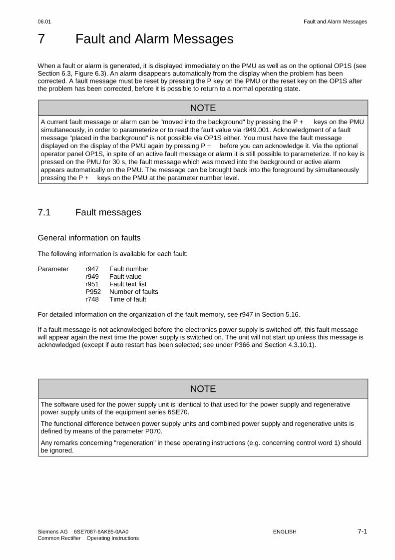
06.01 Fault and Alarm Messages
Siemens AG 6SE7087-6AK85-0AA0 ENGLISH 7-1Common Rectifier Operating Instructions
7 Fault and Alarm Messages
When a fault or alarm is generated, it is displayed immediately on the PMU as well as on the optional OP1S (seeSection 6.3, Figure 6.3). An alarm disappears automatically from the display when the problem has beencorrected. A fault message must be reset by pressing the P key on the PMU or the reset key on the OP1S afterthe problem has been corrected, before it is possible to return to a normal operating state.
NOTE
A current fault message or alarm can be "moved into the background" by pressing the P + keys on the PMUsimultaneously, in order to parameterize or to read the fault value via r949.001. Acknowledgment of a faultmessage "placed in the background" is not possible via OP1S either. You must have the fault messagedisplayed on the display of the PMU again by pressing P + before you can acknowledge it. Via the optionaloperator panel OP1S, in spite of an active fault message or alarm it is still possible to parameterize. If no key ispressed on the PMU for 30 s, the fault message which was moved into the background or active alarmappears automatically on the PMU. The message can be brought back into the foreground by simultaneouslypressing the P + keys on the PMU at the parameter number level.
7.1 Fault messages
General information on faults
The following information is available for each fault:
Parameter r947 Fault numberr949 Fault valuer951 Fault text listP952 Number of faultsr748 Time of fault
For detailed information on the organization of the fault memory, see r947 in Section 5.16.
If a fault message is not acknowledged before the electronics power supply is switched off, this fault messagewill appear again the next time the power supply is switched on. The unit will not start up unless this message isacknowledged (except if auto restart has been selected; see under P366 and Section 4.3.10.1).
NOTE
The software used for the power supply unit is identical to that used for the power supply and regenerativepower supply units of the equipment series 6SE70.
The functional difference between power supply units and combined power supply and regenerative units isdefined by means of the parameter P070.
Any remarks concerning "regeneration" in these operating instructions (e.g. concerning control word 1) shouldbe ignored.
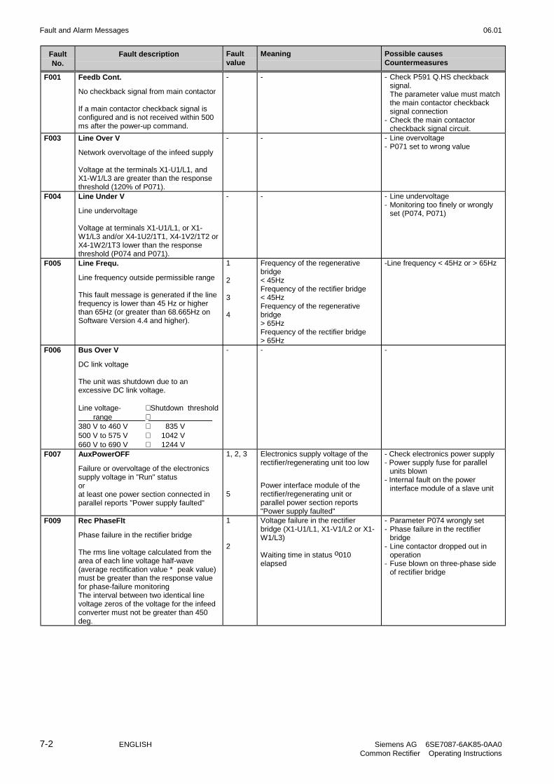
Fault and Alarm Messages 06.01
7-2 ENGLISH Siemens AG 6SE7087-6AK85-0AA0Common Rectifier Operating Instructions
FaultNo.
Fault description Faultvalue
Meaning Possible causesCountermeasures
F001 Feedb Cont.
No checkback signal from main contactor
If a main contactor checkback signal isconfigured and is not received within 500ms after the power-up command.
- - - Check P591 Q.HS checkbacksignal.The parameter value must matchthe main contactor checkbacksignal connection
- Check the main contactorcheckback signal circuit.
F003 Line Over V
Network overvoltage of the infeed supply
Voltage at the terminals X1-U1/L1, andX1-W1/L3 are greater than the responsethreshold (120% of P071).
- - - Line overvoltage- P071 set to wrong value
F004 Line Under V
Line undervoltage
Voltage at terminals X1-U1/L1, or X1-W1/L3 and/or X4-1U2/1T1, X4-1V2/1T2 orX4-1W2/1T3 lower than the responsethreshold (P074 and P071).
- - - Line undervoltage- Monitoring too finely or wrongly
set (P074, P071)
F005 Line Frequ.
Line frequency outside permissible range
This fault message is generated if the linefrequency is lower than 45 Hz or higherthan 65Hz (or greater than 68.665Hz onSoftware Version 4.4 and higher).
1
2
3
4
Frequency of the regenerativebridge< 45HzFrequency of the rectifier bridge< 45HzFrequency of the regenerativebridge> 65HzFrequency of the rectifier bridge> 65Hz
-Line frequency < 45Hz or > 65Hz
F006 Bus Over V
DC link voltage
The unit was shutdown due to anexcessive DC link voltage.
Line voltage- Shutdown threshold range 380 V to 460 V 835 V500 V to 575 V 1042 V660 V to 690 V 1244 V
- - -
F007 AuxPowerOFF
Failure or overvoltage of the electronicssupply voltage in "Run" statusorat least one power section connected inparallel reports "Power supply faulted"
1, 2, 3
5
Electronics supply voltage of therectifier/regenerating unit too low
Power interface module of therectifier/regenerating unit orparallel power section reports"Power supply faulted"
- Check electronics power supply- Power supply fuse for parallel
units blown- Internal fault on the power
interface module of a slave unit
F009 Rec PhaseFlt
Phase failure in the rectifier bridge
The rms line voltage calculated from thearea of each line voltage half-wave(average rectification value * peak value)must be greater than the response valuefor phase-failure monitoringThe interval between two identical linevoltage zeros of the voltage for the infeedconverter must not be greater than 450deg.
1
2
Voltage failure in the rectifierbridge (X1-U1/L1, X1-V1/L2 or X1-W1/L3)
Waiting time in status o010elapsed
- Parameter P074 wrongly set- Phase failure in the rectifier
bridge- Line contactor dropped out in
operation- Fuse blown on three-phase side
of rectifier bridge

06.01 Fault and Alarm Messages
Siemens AG 6SE7087-6AK85-0AA0 ENGLISH 7-3Common Rectifier Operating Instructions
FaultNo.
Fault description Faultvalue
Meaning Possible causesCountermeasures
F010 Inv PhaseFlt
Phase failure in regenerative bridge
The rms line voltage calculated from thearea of each line voltage half-wave(average rectification value x peak value)must be greater than the response valuefor phase-failure monitoringThe interval between two identical linevoltage zeros of the voltage for theregenerating converter must not begreater than 450 deg..
1
2
Voltage failure in the regenerativebridge (X4-1U2/1T1, X4-1V2/1T2or X4-1W2/1T3)Waiting time in status o010elapsed
- Parameter P074 wrongly set- Phase failure in the rectifier
bridge- Line contactor dropped out in
operation- Fuse blown on three-phase side
of rectifier bridge
F022 I2t Overload
I2t monitor of the power section hasresponded
The monitor responds when 100 % of thecalculated I2t value of the power section isreached.
- - - Drive operated too long underoverload conditions
- Check to see whether the ratedcurrent of the R/G unit isadequate for the specificapplication
- See also P785
F023 LT-Temp.
Temperature of the power section too high
A check is made to see whether the heatsink temperature measured usingthermistor(s) is > 95 °C (or 123,9°C)
1 Heat sink temperature > 95 °C
or with water-cooled units:heat sink temperature > 123,9 °C
- Heat sink (air inlets and outlets)contaminated
- Heat sink temperature sensor notconnected to X31, X32 on A1681and/or A1682 module (“slaveunit”)
- Fan has no voltage- Fan faulted- Fan running in the wrong
direction- Fan fuse (F3, F4) defectiveNOTE:- Measure inlet air ambient
temperature. If ϑ > 40 ºC, notereduction curves. See Section14.1.
With water-cooled units:- Water inlet temperature too high,
cooling circuit interrupted orcooling water pump faulty
Temperature of the power section too low 2 Heat sink temperature ≤ -45 °C - Heat sink temperature sensor notconnected to X30 module onA1681 and/or A1682
F029 Measure Flt
Fault in line voltage measurement
An offset > 5% has been detected whenattempting to compensate for the offset ofthe line voltage measurement
1
2
3
4
Channel V-U faulted(regenerative feedbackdirection)
Channel V-W faulted(regenerative feedbackdirection)
Channel W-U faulted(regenerative feedbackdirection)
Channel W-U faulted(infeed direction)
- Fault in the voltage path on thepower interface module (A1681and/or A1682 and/or A1685) oron the electronic module (CUR)
F030 DC Bus Short
DC link short-circuit
The monitor responds if the followingconditions obtain for longer than 0.5 sec:- The current limit of the
rectifier/regenerating unit is reached(this condition does not apply duringcircuit identification or during DC linkforming)
- The rectifier or regenerative current isgreater than 10% of the rated DCcurrent (P075)
- The DC link voltage is less than 5% of1.35*P071
- - - Short-circuit in the DC link
F031 Fuse Blown
Fuse blown in a thyristor branch of therectifier/regenerating unit or of a parallelpower section.
- - - Thyristor branch fuse faulted

Fault and Alarm Messages 06.01
7-4 ENGLISH Siemens AG 6SE7087-6AK85-0AA0Common Rectifier Operating Instructions
FaultNo.
Fault description Faultvalue
Meaning Possible causesCountermeasures
F032 Phase Sequ.?
Wrong phase sequence
A check is make to see whether the phasesequence of the rectifier bridge is thesame as that of the regenerative bridge.
- - - Phase sequence of the rectifierbridge different from that of theregenerative bridge
F033 DC Bus Open
The monitor responds if the followingconditions obtain for longer than 30sec inthe "RUN“ status:- DC link current <1%- Output voltage of the thyristor bridge
oscillates severely
- - - Rectifier fuse defective- No inverter connected
F034 Par PwrSectF
Fault in power sections connected inparallel
At least one parallel power section isconnected, has been selected withparameter P076 and reports the faultmessage "Current asymmetry betweenrectifier/regenerating unit and parallelpower section".
1 Current asymmetry (overcurrent orundercurrent in the parallel powersection compared with the currentin the rectifier/regenerating unit)|Ibasic| - |Iparallel| > 21 %|Iparallel| - |Ibasic| > 14 %for 300 ms
- One of the thyristors is not firing- Different current ripple in the
rectifier/regenerating unit andparallel power section due todifferent commutating reactors
- Cable connection between therectifier/regenerating unit and aparallel power section isinterrupted or faulted
F035 Ext Fault 1
External fault 1
A parameter-programmable fault input hasbecome active.
- - - There is an "External fault 1"signal at the selected binary input(P575/source for "Ext. fault 1")
- The line to the correspondingbinary input is interrupted.
F036 Ext Fault 2
External fault 2
Active in the "RUN“ when the pre-chargingtime (P329) + 3s (200 ms for SW<3.0)has elapsed.
A parameter-programmable fault input hasbeen activated.
- - - There is an "External fault 2"signal at the selected binary input(P586/source for "Ext. fault 2")
- The line to the correspondingbinary input is interrupted..
F038 Ext Fault 3
External fault 3
A parameter-programmable fault input hasbeen activated.
- - - There is an "External fault 3"signal at the selected binary input(P573/source for "Ext. fault 3")
- The line to the correspondingbinary input is interrupted..
F041 EEprom-Fault
Parameter range fault
Software monitoring of the permissiblevalue range of the parameters and thefunctionality of the EEPROM chip(permanent memory) on electronic moduleCUR (type: X28C64, 8192 bytes)
1 "Parameter value outside thepermissible range".
- Software has been replaced- Excessive interference (e.g. by
contactors without RC elements,unshielded cables, faultyshielding connections ...)
- Countermeasures:Acknowledge the faultCheck EMC measuresSet MLFB (Section 4.3.9.2)Establish factory setting (Section4.3.9.1)Repeat system start-up (Section4.2.3)
2 "EEPROM location defective" - Hardware defect- Severe EMC noise- Countermeasures:
Replace the CUR moduleCheck EMC measures.
3 "EEPROM fault" - As for 1
F042 Buffer OFlow
Internal buffer overflow
Software monitoring of various softwarebuffers.
- - - CUR module faulted- Excessive interference (e.g. by
contactors without RC elements,unshielded cables, faultyshielding connections ...)

06.01 Fault and Alarm Messages
Siemens AG 6SE7087-6AK85-0AA0 ENGLISH 7-5Common Rectifier Operating Instructions
FaultNo.
Fault description Faultvalue
Meaning Possible causesCountermeasures
F047 Int Fault
Non-permissible microprocessor status
The microprocessor is monitored byinternal hardware for non-permissiblestates
- - - CUR module faulted- Excessive interference (e.g. by
contactors without RC elements,unshielded cables, faultyshielding connections ...)
F048 RAM Fault
RAM defective
Software-based checking of thefunctionality of the RAM chips on the CURmodule
- - - RAM defective (replace the CURmodule)
F049 Watchdog!
Watchdog timer has triggered a Reset
An internal hardware counter in themicroprocessor checks to see whether theprogram for calculating the firing pulses isexecuted at least about every 400 ms (onaverage, it is executed every 2.7 to 3.3ms). If this is not the case, the countertriggers a Reset. F047 then appears.
- - - CUR module defective- Excessive interference (e.g. by
contactors without RC elements,unshielded cables, faultyshielding connections)
F060 No MLFB
P070=0
- - - After acknowledging inBOOTSTRAP, enter a suitableparameter value for the unit withP070 MLFB (6SEE70..) (onlypossible with the correspondingaccess stages of the two accessparameters; see Section 4.3.9.2).
F061 WrongPar Set
Parameter wrong or not yet set
3 P141 (Rectifier Induct.), P143(Inverter Induct.) or P144 (C of DClink) are = 0.00
- Carry out circuit identification(P052 = 21)
Note about fault value 4, 5:The Ud reduction is then considered to be"selected" if while the basic settingP571.i001 0 active or while the standbysetting P571.i002 0 active, or if P323=1.
4 P318 is too large (with Ud reductionselected) or P776 is set too smallto facilitate constant regenerativeoperation with continuous DC linkcurrent for the current ratio ofrectifier/regenerating supplyvoltage.
As the inverter step limit P776 withrespect to the commutationduration (depending on uK value ofthe network) has an upper limit,P318 has to be set lower, or Udreduction has to be activated viaP571if it is not currently active.The following must apply:
cosP776100%U
UP318
rect. Supply,
reg. Supply,≤
or.if operating without Ud reduction:
cosP776100%U
U100%
rect. Supply,
reg. Supply,≤
5 P318 is too large (with Ud reductionselected) to facilitate constantregenerative operation withpulsating DC link current for thecurrent ratio ofrectifier/regenerating supplyvoltage.
P318 has to be set lower, or Udreduction has to be activated viaP571if it is not currently active.The following must apply:
%62,87U
UP318
rectifier Supply,
ngregenerati supply,≤
orif operating without Ud reduction:
%62,78U
U100%
rectifier Supply,
ngregenerati Supply,≤
Autotransformer connected incorrectly 6
1,1
1 <
U
U
rectifier Supply,
ngregenerati Supply,
7 P076 ≠ 0xx UND Unit is an E unit(P070 ≥ 101)
- Set P076 correctly
8 P076 = 10x, 20x or 21x(i.e. more parallel recovery powersections are parameterized thanparallel feed power sections)
- Set P076 correctly

Fault and Alarm Messages 06.01
7-6 ENGLISH Siemens AG 6SE7087-6AK85-0AA0Common Rectifier Operating Instructions
FaultNo.
Fault description Faultvalue
Meaning Possible causesCountermeasures
F065 SST1 Telegr.
USS telegram to SST1 failed
Active from the first reception of a validprotocol in all operating states
Following receipt of a valid telegram, nofurther telegrams were received for longerthan the time set with parameterP687.i001
- - - Cable break- Fault in the USS master
F066 SST2 Telegr.
Peer-to-peer telegram to SST1 failed
Following receipt of a valid telegram, nofurther telegrams were received for longerthan the time set with parameterP687.i003
- - - Cable break
F070 SCB Initial
SCB initialization error
An error has occurred when initializing theSCB.
1
25610
SCB not plugged in or SCB modulecode wrongSCB not compatibleWrong initialization dataTimeout when initializingError in the configuration channel
- Plug in the SCB- Check the SCB and/or replace it- Correct the initialization data
F072 SCB Heartb.
SCB heartbeat
SCB no longer processes the heartbeatcounter.
- - - Replace the SCB- Check the connection between
the module rack and the optionmodule
F073 Sl1 AnaIn1
Current at analog input 1, slave 1, under 4mA
- - - Check the connection betweenthe signal source and the SCI1-module (slave 1) -X428:4, 5
F074 Sl1 AnaIn2
Current at analog input 2, slave 1, under 4mA
- - - Check the connection betweenthe signal source and the SCI1-module (slave 2) -X428:7, 8
F075 Sl1 AnaIn3
Current at analog input 3, slave 1, under 4mA
- - - Check the connection betweenthe signal source and the SCI1-module (slave 3) -X428:10, 11
F076 Sl2 AnaIn1
Current at analog input 1, slave 2, under 4mA
- - - Check the connection betweenthe signal source and the SCI1-module (slave 3) -X428:4, 5
F077 Sl2 AnaIn2
Current at analog input 2, slave 2, under 4mA
- - - Check the connection betweenthe signal source and the SCI1-module (slave 3) -X428:7, 8
F078 Sl2 AnaIn3
Current at analog input 3, slave 2, under 4mA
- - - Check the connection betweenthe signal source and the SCI1-module (slave 3) -X428:10, 11
F079 SCB Telegr.
SCB telegram failure
Following a correctly received telegram,no further telegram has been receivedwithin the time set with parameterP687.i002.
- - - Check connection to the SCB
F080 TB/CB Init.
An error has occurred when initializing themodule at the DPR interface.
12567
TB/CB not plugged inTB/CB not compatibleError in initializing dataTimeout when initializingTB/TC module code wrong
- Contact problem in connectionbetween module rack and TBand/or CB
- Slot does not agree withassignment (P090, P091)
- Wrong module code r723- Wrong module compatibility r724
F081 TB/CB Heartb
TB/CB heartbeat error
TB or CB has stopped processing theheartbeat counter.
- - - Contact problem in connectionbetween module rack and TBand/or CB
- Hardware fault (replace TBand/or CB)

06.01 Fault and Alarm Messages
Siemens AG 6SE7087-6AK85-0AA0 ENGLISH 7-7Common Rectifier Operating Instructions
FaultNo.
Fault description Faultvalue
Meaning Possible causesCountermeasures
F082 TB/CB Telegr
TB/CB telegram failure
The exchange of data has beeninterrupted.
P695 defines the telegram failure time
12345
678
91011
12
2122
CB alarm channel faultyTB alarm channel faultyTB error channel faultyCB task channel (CB → CUR)faultyCB answer channel (CUR → CB)faultyInternal errorTB task channel (TB → CUR) faultyTB answer channel (CUR → TB)faultyInternal errorCB/TB Telegram failurePMU task channel (CUR → TB)faultyPMU answer channel (TB → CUR)faultyCB/TB setpoint channel faultyCB/TB actual value channel faulty
-
F090 Circuit ID F
Circuit identification not possible
1 If generating mode is inhibited(P076 = xx1), circuit identificationis not possible!
- Set P076 = x2
2 If α = 30°, not enough rectifiercurrent flows (less than 25% of therated DC current withP160=150.0% or less than 10%with P160=60.0%)
- Connection to DC link interrupted
3 P141 (Rectifier Induct.) and/orP143 (Inverter Induct.) and/or P144(C for DC link) could not beidentified
- Commutating inductance too low(see Section 3.1)
- Connection to DC link interrupted
4 A waiting time of 20s has alreadyelapsed but the circuit identificationcannot be carried out because theDC link voltage is too high(Ud>20% of 1.35*P071)
- Another unit is supplying the DClink
- Wait until the DC link hasdischarged sufficiently, then startcircuit identification again
F091 Circuit ID C
Circuit identification or forming aborteddue to external cause.
If circuit identification is aborted, onlythose parameters are modified whoseassignment was completed before thisfault occurred.
1
2
3
4
5
The abort took place because theRUN or "R" status was exited forsome reason (e.g. brief poweroutage) during forming or circuitidentification.The abort took place because thereserve data set selection changedduring forming or circuitidentification.The abort took place because theOFF command was given.The abort took place because anON command was not given within20 sec after selecting the formingfunction (P052=20) or the circuitidentification function (P052=21)The abort took place because the"Inhibit regenerating" commandwas given during circuitidentification (see control word 1,bit 12 and P572)
-

Fault and Alarm Messages 06.01
7-8 ENGLISH Siemens AG 6SE7087-6AK85-0AA0Common Rectifier Operating Instructions
FaultNo.
Fault description Faultvalue
Meaning Possible causesCountermeasures
F103 Thy/Grnd Flt
Fault when conducting thethyristor/ground-fault test
This fault message can only occur if thethyristor/ground-fault test is activated withparameters P353 / P354.A software check is made to see whetherall thyristors have blocking capability,whether they can be fired, and whetherthere is a ground faultIdentification of the firing lines and theassociated thyristors should always bemade with the aid of the relevant wiringdiagram (see Section 3-5 "Powerterminals").
1
2
3
4
5
6
Short-circuit of thyristor V11 or V24
Short-circuit of thyristor V12 or V25
Short-circuit of thyristor V13 or V26
Short-circuit of thyristor V14 or V21
Short-circuit of thyristor V15 or V22
Short-circuit of thyristor V16 or V23
- Thyristor defective- Thyristor externally shorted
(e.g. by ground fault in groundedsystem and ground fault in themotor)
- Connection to DC link interrupted(e.g. fuse blown)
Possible reasons for the thyristorbeing defective:- Interruption in the RC circuit- Converter and compensation
control not optimized (excessivecurrent peaks)
- Cooling not guaranteed (e.g. fannot running, ambient temperaturetoo high, to little air intake, heatsink severely contaminated)
- Excessive voltage peaks insupply system
8 Ground fault in DC link or in motor/ rectifier fuse defective
- Ground fault- Connection to DC link interrupted
(e.g. fuse blown)9 I = 0 - Message defective - CUR module defect
111213141516
Thyristor cannot be fired (X11)Thyristor cannot be fired (X12)Thyristor cannot be fired (X13)Thyristor cannot be fired (X14)Thyristor cannot be fired (X15)Thyristor cannot be fired (X16)
- Firing pulse line to relevantthyristor interrupted
- Ribbon cable X109 not correctlyplugged in or interrupted (andribbon cable X27 in the case ofpower section connected inparallel)
- Defect in electronics and/orpower interface module
- internal interruption on the gateline in the thyristor module
17 2 or more thyristors of the rectifierbridge cannot be fired
- Connection to DC link interrupted(e.g. fuse blown)
- As under 11 to 16212223242526
Thyristor cannot be fired (X21)Thyristor cannot be fired (X22)Thyristor cannot be fired (X23)Thyristor cannot be fired (X24)Thyristor cannot be fired (X25)Thyristor cannot be fired (X26)
- As under 11 to 16
27 2 or more thyristors of theregenerative bridge cannot be fired
- Parameter P076 wrong- As under 11 to 16
31
32
33
34
35
36
Thyristor cannot block(gate X11 or X21)Thyristor cannot block(gate X12 or X22)Thyristor cannot block(gate X13 or X23)Thyristor cannot block(gate X14 or X24)Thyristor cannot block(gate X15 or X25)Thyristor cannot block(gate X16 or X26)
- As under 1 to 6
F116 toF150
Fault on the intelligent I/O module
See User's Manual of the TB module
- - -

06.01 Fault and Alarm Messages
Siemens AG 6SE7087-6AK85-0AA0 ENGLISH 7-9Common Rectifier Operating Instructions
7.2 Alarm messages
The warning message appears periodically as A=Alarm/Warning and a three-digit in the display of the PMU Awarning cannot be acknowledged. It extinguishes automatically when the cause of the warning is eliminated.Several messages may occur at the same time, in which case they appear one after the other in the display.If the common rectifier is operated with the OP1S operator panel, the warning appears in the bottom line of thedisplay. The red LED starts blinking first (see the operating instructions for the OP1S)
AlarmNo.
ParameterNo.
Bit No.
Description Countermeasures
A015 P953
14
ext.Warn 1
Parameter-programmable external warning input 1has been activated
External warning arrived! Check whether the line to therelevant binary input is interrupted.Check parameter P588 Src No Ext Warn 1.See also Section 4.3.2.
A016 P953
15
ext. Warn 2
Parameter-programmable external warning input 1has been activated
External warning arrived! Check whether the line to therelevant binary input is interrupted.Check parameter P589 Src No Ext Warn 2.See also Section 4.3.2.
A022 P954
5
LT-Temp.
The heat sink temperature is > 90 °C
or with water-cooled units:The heat sink temperature is > 118 °C
Measure inlet air and/or ambient temperature. If ϑ >40°C, note the reduction curves. See Section 14.1.
Check
- whether fan -E1(-E2) is connected and rotating in theright direction.
- whether the air inlet and outlet openings are clean andclear.
- the connection of the temperature sensor to -X30(-X31, -X32).
With water-cooled units:- Water inlet temperature too high, cooling circuit
interrupted or cooling water pump faulty
A025 P954
8
I2t Warning
The I2t value of the power section is too high. Thewarning is triggered when 90% of the permissibleI2t value is reached. See also under fault F022 andparameter P785. The permissible I2t value isreached at the maximum permissible load cycle(see Section 14, Figure 14.1)
Check whether the rated DC current of therectifier/regenerating unit is adequate for the specificapplication.

Fault and Alarm Messages 06.01
7-10 ENGLISH Siemens AG 6SE7087-6AK85-0AA0Common Rectifier Operating Instructions
AlarmNo.
ParameterNo.
Bit No.
Description Countermeasures
A049 P956
0
no Slave
In the case of serial I/O (SCB1 with SCI1/2), noslave is connected and/or the fiber optic conductoris interrupted or the slaves have no voltage.
P660 SCI AnalogInConf
Check the slave.Check the cable.
A050 P956
1
Slave not ok
In the case of serial I/O, the slaves requiredaccording to the parameter settings are notavailable (slave number an/or slave type).
Check P660 SCI AnalogInConf
A051 P956
2
Peer Bdrate
In a peer-to-peer connection, the baud rateselected is too high and/pr different
Match the baud rates of the SCB modules connected toeach (P684 SST/SCB Baudrate)
A052 P956
3
Peer PrD-L
In a peer-to-peer connection, an excessiveprocess data length has been set (>5).
Reduce the number of words
P686 SCom/SCB # PrDat.
A053 P956
4
Peer Lng f.
In a peer-to-peer connection, the process datalength of the sender and receiver do not agree
Match the word lengths of the sender and receiverP686 SCom/SCB # PrDat
A065 P957
0
Auto Restart
The line voltage is outside the tolerance band atthe moment (e.g. power outage). The firing pulsesare therefore inhibited. On power recovery,however, the WEA option (P366) implements anauto restart.
Important
An auto restart may constitute a danger for persons andproperty. Make sure you really want to have auto restart(WEA).
If necessary, change P366 WEA.
A081..
A096
r958
0...15
CB Warning 1...16
See user's manual for the CB module
A097..A112
r959
0...15
TB Warning 1 16
See user's manual for the TB module
A113..A128
r960
0...15
TB Warning 17...32
See user's manual for the TB module

06.01 Maintenance
Siemens AG 6SE7087-6AK85-0AA0 ENGLISH 8-1Common Rectifier Operating Instructions
8 Maintenance
WARNING
The common rectifiers are operated with high voltages.
All work on the unit must be carried out in agreement with the national electrical regulations(in Germany: VBG 4).
Maintenance and repair work must only be carried out by qualified personnel.
Use must only be made of the spare parts approved by the manufacturer.
It is imperative to observe the prescribed maintenance intervals and the repair andreplacement instructions.
As the result of the dc link capacitors in the connected SIMOVERT Master Drives, the unitstill contains a hazardous voltage up to 5 min. after isolation (power terminal and electronicpower supply). This is why it is only permitted to open the unit after observing anappropriate waiting time.
In spite of de-energisation of the power connections and discharge of the DC link thesnubber capacitors remain charged with the gate control module A23 disconnected.
The power and control terminals may still be live even in the event of motor standstill.
Despite disconnecting the power terminals from the supply, terminal X19 may still be livedue to the external fan supply.
If work on the activated unit is necessary:
♦ do not touch any live parts.
♦ use only proper measuring equipment and protective work clothing.
♦ stand or sit on an unearthed and isolated surface that does justice to ESD requirements.
Non-observance of warning notices can result in death, severe personal injury orconsiderable property damage.
You should know the order and factory numbers of your unit when consulting the service department. You willfind these numbers and other important data on the rating plate of the unit.
8.1 Maintenance recommendations
The fans are designed for a service life of 40,000 hours at an ambient temperature of TA = 40 °C. To guaranteethe availability of the unit at all times, the fans must be replaced in good time.

Maintenance 0601
8-2 ENGLISH Siemens AG 6SE7087-6AK85-0AA0Common Rectifier Operating Instructions
8.2 Replacing components
8.2.1 Replacing the fan
WARNING
The fan must only be replaced by qualified personnel.
As a result of the DC link capacitors and snubber capacitors in the connectedinverters, a hazardous voltage still exists for up to 5 min after isolation.
Non-observance of warning notices can result in death, severe personal injury orconsiderable property damage.
Size H
The fan is located in the fan box on the top of the unit.
♦ Unplug X20.
♦ Undo both M8 (SW 13) fixing screws.
♦ Loosen the two M4 fixing screws and swing the plasticcover out sideways..
♦ Pull the fan box out of the unit forwards as far as thestop.
♦ Then lift it up over the stop (at the back) and remove itcompletely from the unit.
♦ Installation is carried out in reverse order.Important!The two M8 fixing screws are used to earth the fanbox, so they must be screwed down firmly.
X20
M8 M8
M4
Fan E1
Figure 8.1 Fan (AC 230V) for size H
Size K
The two fans are located in the fan box on the top of theunit.
♦ Unplug X20.
♦ Undo both M8 (SW 13) fixing screws.
♦ Pull the fan box out of the unit forwards.
♦ Installation is carried out in reverse order.X20
M8
Fan E1 Fan E2
Figure 8.2 Fan (AC 230V) for size K
WARNING
The fan box weighs approx. 16 kg for size H, and approx. 32 kg for size K. This must betaken into account when removing the fan box.
Non-observance of warning notices can result in severe personal injury or considerableproperty damage.

06.01 Maintenance
Siemens AG 6SE7087-6AK85-0AA0 ENGLISH 8-3Common Rectifier Operating Instructions
8.2.2 Replacing modules
WARNING
Modules must only be replaced by qualified persons.
Modules must not be removed or inserted under a live voltage.
Non-observance of warning notices can result in death, severe personal injury orconsiderable property damage.
CAUTION
The modules contain electrostatically sensitive devices. You must discharge your own bodybefore touching an electronic module. This is best done by touching a conductive earthedobject (e.g. a bare metal part of the control cabinet) directly beforehand.
Replacing modules in theelectronics box
♦ Undo the securing screwsof the modules above andbelow the insertion /removalaids.
♦ By means of the insertion/removal aids, carefully pullthe module out of theelectronics box, makingsure that the module doesnot get stuck.
♦ Carefully insert the newmodule in the guide railsuntil it moves no further inthe electronics box.
♦ Firmly screw down themodule with the securingscrews above and belowthe insertion / removal aids.
S lot 3 (O ptions)S lot 1 (CU R)
Slot 2 (O ptions)
Figure 8.3 Electronics box, equipped with CUR (slot 1)
and options (slots 2 and 3)

Maintenance 0601
8-4 ENGLISH Siemens AG 6SE7087-6AK85-0AA0Common Rectifier Operating Instructions
NOTE
When replaced under MLFB 6SE7090-0XX85-1DA0, the PCB electronics CUR (C98043-A1680) is suppliedprogrammed without EPROM (software). The EPROM programmed (last state) must be ordered separately,as must the operating instructions for a new software version.Example of replacement part ordering of a CUR with accessories:
PCB electronics (CUR) 6SE7090-0XX85-1DA0
EPROM programmed 6SW1701-0DA14
Operating instructions Common Rectifier e.g. German/English 6SE7087-6AK85-0AA0
Assigning the "Start-up" parameters for the CUR option module (A10)
For general information see Chapter 4
Switch over from fault display to parameterization
Access stage "Expert mode“
MLFB setting (initialization)
WARNING
Initialization is mandatory.
Specify the ID number of the MLFB in P070 of thecommon rectifier (rating plate on the unit) as per MLFBtable Section 4.3.9.2.
P051 = 3
P052 = 2
P070 =
F060
P052 = 0
See Section4.2.2 or 4.2.3
P and Higher key
P and Lower keyP-key
Return from setting MLFB
Change back to fault display andacknowledge F060
WARNING
Replacing firing-circuit module A23
Carry out circuit identification after replacing the A23 (see Chapter 4).
The earth connection must be restored by tightening the screws marked with an earthingsign on the electronics box (size H) or on the electronics slide-in unit (size K).

06.01 Maintenance
Siemens AG 6SE7087-6AK85-0AA0 ENGLISH 8-5Common Rectifier Operating Instructions
Replacing the EPROM on the CUR module (upgrading to a new software version)
On setup and during servicing work, the current parameter settings in the logbook in Chapter 12 should besaved For information on reading out the parameters changed from the factory settings easily, see Section4.3.9.3 (saving the parameter values using SIMOVIS) and Section 4.3.9.8 (displaying modified parameters). Itshould be checked that these entries are up-to-date before the EPROM is replaced because when theelectronics supply voltage is switched on again, the function "generate factory settings" is carried outautomatically (see Section 4.3.9.1). Then only the values of parameters P070 and P077 are retained.
WARNING
The EPROM must only be replaced by qualified persons. The EPROM mustnot be removed or inserted under a live voltage.Non-observance of warning notices can result in death, severe personal injuryor considerable property damage.
The EPROM is located in slot D14 of module CUR.
CAUTION
The modules contain electrostatically sensitive devices. You must discharge your ownbody before touching an electronic module. This is best done by touching a conductiveearthed object (e.g. a bare metal part of the control cabinet) directly beforehand.
Procedure for replacing EPROMs:
♦ Switch off electronics supply voltage
♦ Undo fixing screws for module CUR above and below the insertion/removal aids
♦ Remove the module from the electronics box carefully with the help of the insertion/removal aids.
♦ Remove old EPROM carefully from the socket and replace it with a new EPROM. It is important to ensurethat the EPROM is mounted the right way round (pin 1 aligned correctly) and that pins are not bent
♦ Slide module into the electronics box carefully in the guide rails as far as the stop
♦ Screw the module into place again using the fixing screws
♦ After switching the electronics supply voltage on again, wait until the function "generate factory setting" iscomplete. Then restore the parameter values in accordance with the logbook or reload the values savedusing SIMOVIS into the unit.
♦ If the parameters are restored in accordance with the logbook, circuit identification (see Section 4.3.9.7) mustbe carried out (due to special parameter P772).

Maintenance 0601
8-6 ENGLISH Siemens AG 6SE7087-6AK85-0AA0Common Rectifier Operating Instructions
8.2.3 Power interface module spare parts
Load resistors:
NOTE
Replacement modules are supplied without load resistors (e.g. take them over from the original module)!
No liability will be accepted for damage caused by the installation of incorrect load resistors.
If the load resistors (R75 to R78) are not installed, the converter will be destroyed.
Dimensioning of the load resistors:
Idav [A]
Rating plate
R75 R76
[[[[ΩΩΩΩ]]]]
R77 R78
[[[[ΩΩΩΩ]]]]
R79 R80
[[[[ΩΩΩΩ]]]]
Voltage class 480V
821 4,7 10 10
1023 4.7 4,7 12
1333 18 12 12
1780 8,2 11 12
Voltage class 600V
774 4,7 11 12
1023 4,7 4,7 12
1285 10 33 12
1464 12 12 13
1880 8,2 10 11
Voltage class 690V
774 4,7 11 12
1023 4,7 4,7 12
1285 10 33 12
1464 12 12 13
1880 8,2 10 11
Resistors of series W97041.. tolerance: 0.50% for R ≤ 10Ω0.25% for 10Ω < R < 47Ω R79 and R80 not envisaged on A1681.
0.10% for R ≥ 47Ω
The load resistance setpoint refers to the DC link current Idav stated on the rating plate.

06.01 Maintenance
Siemens AG 6SE7087-6AK85-0AA0 ENGLISH 8-7Common Rectifier Operating Instructions
Position of the load resistors:
C98043-A1685
7A T 25 0V
7A T 25 0V
1 5
X 9 X 9
X29
2 132 1
X19
F4
F3
X47
X48
2A
T
25
0V
F5
2A
T
25
0V
F1
2A
T
25
0V
F2
R 79
R 77
R 75
R 76
R 78
R 80

Maintenance 0601
8-8 ENGLISH Siemens AG 6SE7087-6AK85-0AA0Common Rectifier Operating Instructions
8.2.4 Replacing thyristor blocks
8.2.4.1 Disassembling the thyristor blocks for size H
12 9
GK
GK
GK
GK
GK10
11
3
2
2
4
7
8
5
5
11
7 10
8
7
8
6
1
Level ALevel B
Front thyristor block, level A (weight of a thyristor block, approx. 4kg)
• Swing up the door α after loosening the 2 M4 slit Torx screws σ.
• Detach cable δ from the modules and the screen fixture.
• Remove the 2 M6 hexagon head screws φ and swing out the electronic assembly tray to the stop.
• Only in the case of disassembly of the centre thyristor assembly, open the 4 twist-loks γ and release the
cable η for the thermocouple sensor, which is mounted on the centre heat sink only.
• Unplug the gate and cathode cables (G, K) ϕ.
• Remove the 2 M8 hexagon head screws κ and swing out the thyristor assembly to the front.
• Loosen M6 nut λ and pull the thyristor block out upwards at an angle.
Rear thyristor block, level B (weight of a thyristor block, approx. 4 kg)
• Unplug the gate and cathode cables(G, K) ;.
• Remove 2 M8 hexagon-head bolts Α.
• Loosen M6 nut Σ and pull the thyristor block out upwards at an angle.
The thyristor blocks are installed in the reverse order.

06.01 Maintenance
Siemens AG 6SE7087-6AK85-0AA0 ENGLISH 8-9Common Rectifier Operating Instructions
8.2.4.2 Disassembling the thyristor blocks for size K
126
7
1
2
4
3
1
3
3
913
11
10 6
8
5
5
12
4
5
8
11
G K G K G K
Level ALevel B
Front thyristor block, level A (weight of a thyristor block, approx. 12 kg)
• Remove the 2 covers α by loosening 4 M4 hexagon head screws σ and 3 M4 hexagon head screws δ.
• Remove the copper plate φ by removing 4 M10 hexagon-head bolts γ.
• Unplug the gate and cathode cables (G, K) η.
• Only in the case of disassembly of the centre thyristor assembly, remove the thermocouple sensor, which is
mounted on the centre thyristor assembly only by loosening the screw ϕ (Torx drive T25).
• Loosen the two M10 hexagon-head screws κ and swing the thyristor block out forwards.
• Loosen M10 nut λ and pull the thyristor block out upwards at an angle.
Rear thyristor block, level B (weight of a thyristor block, approx. 12 kg)
• Unplug gate and cathode cables (G, K) ;.
• Remove 2 M10 hexagon-head screws Α.
• Remove 2 M10 hexagon-head screws Σ.
• Loosen M10 nut ∆, swing the thyristor block out forwards and pull the thyristor block out upwards at an angle.
The thyristor blocks are installed in the reverse order.

Maintenance 0601
8-10 ENGLISH Siemens AG 6SE7087-6AK85-0AA0Common Rectifier Operating Instructions

06.01 Options
Siemens AG 6SE7087-6AK85-0AA0 ENGLISH 9-1Common Rectifier Operating Instructions
9 Options
9.1 Options which can be integrated into the electronics box
One or two option boards, listed in Table 9.1, can be inserted in the electronics box using the LBA option (LocalBus Adapter, backplane wiring).For use of modules CBC and CBP2, an ADB (adapter board) is required in addition to the LBA. These modulesmust be plugged into an ADB because of their smaller mechanical dimensions before they can be plugged intoan electronics box.
Designation Description Order No.
LBA Local bus adapter for the electronics boxLBA is always needed to install supplementary boards
6SE7090-0XX84-4HA0
ADB Adapter boardADB is always needed to install CBC, CBP, EB1, EB2, SBP andSLB boards
6SX7010-0KA00
CBP2 Communications board with interface for SINEC- L2-DP(PROFIBUS)(miniature-format board; ADB required)
6SX7010-0FF05
CBC Communications board with interface for CAN protocol(miniature-format board; ADB required)
6SX7010-0FG00
SCB1 Serial communications board with fiber-optic cable for serial I/Osystem and peer-to-peer connection
6SE7090-0XX84-0BC0
Description 6SE7080-0CX84-0BC0
Serial communications board for peer-to-peer connection and USSprotocol via RS485
6SE7090-0XX84-0BB0
Description 6SE7080-0CX84-0BB0
SCB2
Use of the serial interface with USS protocol 6SE7087-6CX87-4KB0
T100 Module incl. hardware operating instructions without softwaremodule
6SE7090-0XX87-0BB0
Hardware operating instructions for T100 6SE7080-0CX87-0BB0
MS100 MS100 "Universal Drive“ software module for T100 (EPROM)without manual
6SE7098-0XX84-0BB0
Manual for MS100 "Universal Drive" software module
German 6SE7080-0CX84-0BB1
English 6SE7087-6CX84-0BB1
French 6SE7087-7CX84-0BB1
Spanish 6SE7087-8CX84-0BB1
Italian 6SE7087-2CX84-0BB1
T300 Technology board with 2 connecting leads, SC58 and SC60,terminal block SE300 and hardware operating instructions
6SE7090-0XX87-4AH0
T400 Technology board (incl. short description) 6DD1606-0AD0
Hardware and configuring manual 6DD1903-0EA0
Table 9.1 Option boards and bus adapter

Options 06.01
9-2 ENGLISH Siemens AG 6SE7087-6AK85-0AA0Common Rectifier Operating Instructions
The following additional modules can be supplied under two order numbers
• under the order number of the board without accessories (such as connectors and Short Guide)
• as a retrofit kit: Board with connectors and Short Guide
Board Order number of board (w/o accessories) Order number of retrofit kit
ADB 6SE7090-0XX84-0KA0 6SX7010-0KA00
CBP2 6SE7090-0XX84-0FF5 6SX7010-0FF05
CBC 6SE7090-0XX84-0FG0 6SX7010-0FG00
Slots in the electronics box Boards
Left Slot 1 (CUR) CUR
Center Slot 3 (options) CB1 / SCB1 / SCB2 / CBC (with ADB) / CBP (with ADB)
Right Slots 2 (options) CB1 / CB2 / CBP (with ADB) / CBC (with ADB) / SCB1 /SCB2 / T100 / T300
NOTEOnly one of each option board type may inserted in the electronics box.
TB (technology boards, e.g. T300) must always be inserted at slot 2.
If only one option board is used it must always be inserted at slot 2.
Small format modules (CBP and CBC) must be plugged in on the adapter board on the right or below (in Slot Eor if a technology module is also used in Slot G).
Use of Slots D and F on adapter boards is not possible because the module plugged in there is not detected bythe basic device.
Table 9.2 Slots for option boards in the electronics box
Local bus adapter (LBA) for mounting optional supplementary boards
Optional supplementary boards can be installed only in conjunction with the LBA option. If an LBA is not alreadyfitted in the common rectifier, one must be installed in the electronics box to accommodate the optional board.
How to install an LBA local bus adapter in the electronics box:
- Undo the two fixing screws on the CUR boardand pull board out by special handles.
- Push LBA bus extension into electronics box(see picture on right for position) until itengages.
- Insert CUR board in left-hand board locationagain and tighten fixing screws in handles.
Location 2 (Optionen)Location 3 (OptionenLocation 1 (CUD1)
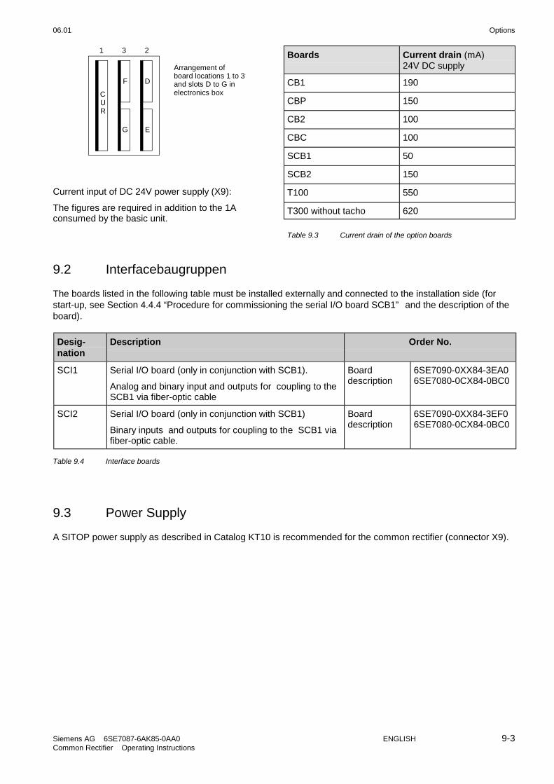
06.01 Options
Siemens AG 6SE7087-6AK85-0AA0 ENGLISH 9-3Common Rectifier Operating Instructions
Boards Current drain (mA)24V DC supply
CB1 190
CBP 150
CB2 100
CBC 100
SCB1 50
SCB2 150
T100 550
T300 without tacho 620
CUR
F D
EG
1 3 2
Arrangement ofboard locations 1 to 3and slots D to G inelectronics box
Current input of DC 24V power supply (X9):
The figures are required in addition to the 1Aconsumed by the basic unit.
Table 9.3 Current drain of the option boards
9.2 Interfacebaugruppen
The boards listed in the following table must be installed externally and connected to the installation side (forstart-up, see Section 4.4.4 “Procedure for commissioning the serial I/O board SCB1” and the description of theboard).
Desig-nation
Description Order No.
SCI1 Serial I/O board (only in conjunction with SCB1).
Analog and binary input and outputs for coupling to theSCB1 via fiber-optic cable
Boarddescription
6SE7090-0XX84-3EA06SE7080-0CX84-0BC0
SCI2 Serial I/O board (only in conjunction with SCB1)
Binary inputs and outputs for coupling to the SCB1 viafiber-optic cable.
Boarddescription
6SE7090-0XX84-3EF06SE7080-0CX84-0BC0
Table 9.4 Interface boards
9.3 Power Supply
A SITOP power supply as described in Catalog KT10 is recommended for the common rectifier (connector X9).

Options 06.01
9-4 ENGLISH Siemens AG 6SE7087-6AK85-0AA0Common Rectifier Operating Instructions
9.4 Operator control panel OP1S
Option Beschreibung
OP1S User-friendly operator control panel with plain textdisplay
Order No.: 6SE7090-0XX84-2FK0
Table 9.5 Operator control options
The optional comfort version of the operator panel with aplaintext display is plugged into the position in the device doorintended for that purpose.
It is thus connected to the serial basic device interface SST1.
If the UP or DOWN keys of the OP1S is used to selectadjacent parameter numbers, the missing numbers areskipped in the range of the basic device parameters.
With parameters of a technology module, this automaticskipping of missing numbers is not possible. In that case, thenumbers of the existing parameters must be entered directly.
P
Fault
Run
0 +/- Reset
1 2 3
654
7 8 9Jog
O
I
Figure 9.1 OP1S
The OP1S provides the option of selecting parameters directly by entering their number on the keyboard. Thefollowing applies:
Displayed number Number to be entered on the OP1S
Basic deviceparameter
rxxx, Pxxx (0)xxx
Parameter of atechnology module
Hxxx, dxxx 1xxx
A few seconds after initialization of the OP1S, the displayautomatically switches to the operating display.
From the operating display, you can enter the basic menu bypressing the <P> key. Here either "free access" to all parameters ordifferent functions can be selected. Details of the functions can befound in the OP1S operating instructions.
In the state "free access", parameterization of the device ispossible.
If you press the <R> key (several times if necessary), you canreturn to the operating display.
Operating display
Basic menu
Free access
<P>
<P> <R>
<R>

06.01 Options
Siemens AG 6SE7087-6AK85-0AA0 ENGLISH 9-5Common Rectifier Operating Instructions
With SIMOVERT 6SE70 the following values are displayed on the operating display:
1st line DC link current actual value r035 [%] DC link voltage r006 [V] Bus addr.
2nd line # DC link voltage actual value r037 [%]
3rd line * DC link voltage setpoint r036 [%]
4th line Operating state r001
The following parameters affect the function of the OP1S or of the interface SST1:P050 (language selection), P051 (access level), P053 (parameterization enable), P054 (OP backlighting), P683to P687 (interface settings)
Control bits of the operator panel OP1S:
(See also the operating instructions for the OP1S)
Communication between the OP1S and the SIMOREG device 6RA70 is performed via the interface G-SST1(RS485) using the GPI protocol.
By pressing the appropriate key on the OP1S, it is possible to execute functions. The OP1S sets the appropriatecontrol word bit in PZD word 1 by means of transmission by the GPI protocol. (For details of the control wordbits, see Chapter 4.3.1.1)
For activation of the required function, parameterization as shown in the table below is required.
Key on OP1S Function Bit in PZD word 1 Activation by
On/off key (I / 0) ON / OFF1 Bit 0 P554 = 2001
Reset Acknowledgment *) Bit 7 P565, P566, or P567 = 2001
Jog Jogging Bit 8 P568 = 2001
Reversal Ud reduction Bit 11 P571 = 2001
Regenerativefeedback enable
Bit 12 P572 = 2001
*) Acknowledgment of the fault messages using the <Reset> key of the OP1S is only possible in the operatingdisplay, i.e. the operating display must first have been selected by pressing the <Reset> key (several times).Independently of that, acknowledgment is always possible by pressing the <P> key on the PMU.
NOTE
The predecessor of the OP1S (the OP1) cannot be used with software version V4.0 and higher because of itsdiffering coupling mechanisms! The OP1S, however, is a suitable replacement for the OP1 if used with olderdevice software.
9.5 RS485 interface (PTP1)
The SST2 serial interface for the basic unit is not available until submodule A2 (C98043-A1690-L1) has beenplugged into the CUR electronics module (A10).
With the parameterization P688=1, the peer-to-peer transmission protocol is implemented on SST2.
The RS485 interface cable required for peer-to-peer coupling to a second unit is described in Section 3.8.7.
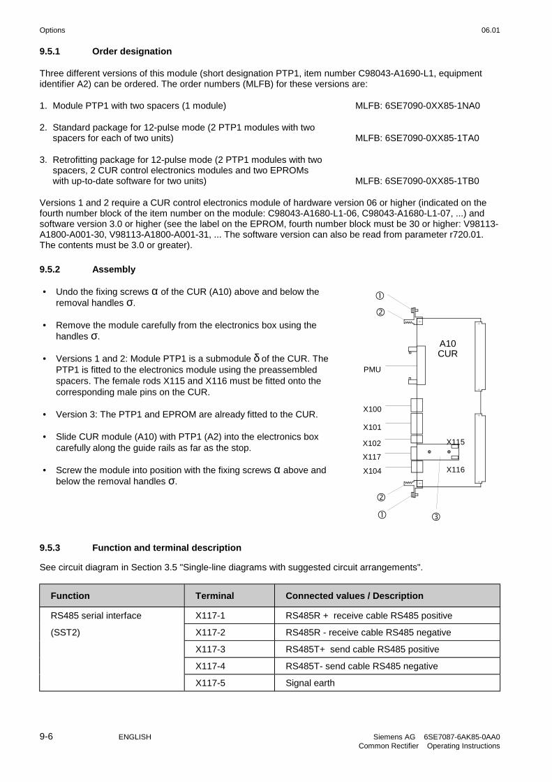
Options 06.01
9-6 ENGLISH Siemens AG 6SE7087-6AK85-0AA0Common Rectifier Operating Instructions
9.5.1 Order designation
Three different versions of this module (short designation PTP1, item number C98043-A1690-L1, equipmentidentifier A2) can be ordered. The order numbers (MLFB) for these versions are:
1. Module PTP1 with two spacers (1 module) MLFB: 6SE7090-0XX85-1NA0
2. Standard package for 12-pulse mode (2 PTP1 modules with twospacers for each of two units) MLFB: 6SE7090-0XX85-1TA0
3. Retrofitting package for 12-pulse mode (2 PTP1 modules with twospacers, 2 CUR control electronics modules and two EPROMswith up-to-date software for two units) MLFB: 6SE7090-0XX85-1TB0
Versions 1 and 2 require a CUR control electronics module of hardware version 06 or higher (indicated on thefourth number block of the item number on the module: C98043-A1680-L1-06, C98043-A1680-L1-07, ...) andsoftware version 3.0 or higher (see the label on the EPROM, fourth number block must be 30 or higher: V98113-A1800-A001-30, V98113-A1800-A001-31, ... The software version can also be read from parameter r720.01.The contents must be 3.0 or greater).
9.5.2 Assembly
• Undo the fixing screws α of the CUR (A10) above and below theremoval handles σ.
• Remove the module carefully from the electronics box using thehandles σ.
• Versions 1 and 2: Module PTP1 is a submodule δ of the CUR. ThePTP1 is fitted to the electronics module using the preassembledspacers. The female rods X115 and X116 must be fitted onto thecorresponding male pins on the CUR.
• Version 3: The PTP1 and EPROM are already fitted to the CUR.
• Slide CUR module (A10) with PTP1 (A2) into the electronics boxcarefully along the guide rails as far as the stop.
• Screw the module into position with the fixing screws α above andbelow the removal handles σ.
X100
X101
X102
PMU
X104
X117
X115
X116
A10CUR
9.5.3 Function and terminal description
See circuit diagram in Section 3.5 "Single-line diagrams with suggested circuit arrangements".
Function Terminal Connected values / Description
RS485 serial interface X117-1 RS485R + receive cable RS485 positive
(SST2) X117-2 RS485R - receive cable RS485 negative
X117-3 RS485T+ send cable RS485 positive
X117-4 RS485T- send cable RS485 negative
X117-5 Signal earth

06.01 Options
Siemens AG 6SE7087-6AK85-0AA0 ENGLISH 9-7Common Rectifier Operating Instructions
The bus termination resistors required for peer-to-peer mode are installed on the module::
• 150Ω between terminal X117-1 and terminal X117-2• 390Ω from terminal X117-1 to +5V supply• 390Ω from terminal X117-2 to ground
9.5.4 Parameterization
The following parameters influence the function of the SST2 interface for the basic unit (for details see Section5.12):
P681 (i001 to i005) Selection of process data for transmission
P684.i003 Baudrate
P686.i003 Number of net data words for peer-to-peer link
P687.i003 Telegram failure time
P688 Selection of the protocol
Parameterization for "12-pulse mode" see Section 3.8.3.
9.6 SIMOVIS
WARNING
Only qualified personnel who are familiar with the SIMOVIS operatinginstructions and with the operating instructions of the connected devices andtheir safety instructions are permitted to intervene at the drive using the PC.
Incorrect use of the software can result in death, severe personal injury orconsiderable property damage.
What is SIMOVIS?
SIMOVIS is a program that runs on standard PCs for the setup and diagnostics of converters.
The connection between SIMOVIS on the PC and the converter units is implemented via the serial interface(X300 on the PMU or X100 on the module CUR) using the GPI protocol.
NOTE
Communication can be effected either via the terminal strip of the CUR-X100 (RS485 interface) or the interfaceconnector of the PMU-X300 (9-way SUB D connector, RS485-/RS232 interface).
It is only possible to operate one of the two possible connections (X100 or X300)!
X100 is only implemented as an RS485 interface.On hardware version 07 and higher of the electronics board (C98043-A1680-L1-07), X300 is implemented as acombined RS485/RS232 interface. This makes it possible to establish the connection between the X300 and theserial interface on the PC (COM1 or COM2) also using the RS232 .Up to hardware version 06 and higher, X300 was only a RS485 interface. An interface adapter must therefore beused for the connection between X300 and the serial interface on the PC, if the PC does not have an RS485interface.An RS485/RS232 adapter is available under order number 6SX7005-0AA00.

Options 06.01
9-8 ENGLISH Siemens AG 6SE7087-6AK85-0AA0Common Rectifier Operating Instructions
SIMOVIS functions
• Menu-driven setting up using the PC: all parameters can be set that are required for operation.
• Reading and writing any preferred parameter sets (Upread, Download).
• Setting and monitoring all parameters of the unit using graphical methods.
• Operation of the unit via screen forms. Issuing control commands.
• Evaluation of faults and alarms: Overview of faults and alarms for all equipment connected to the bus.
SIMOVIS is supplied with every unit, on diskette, in the diskette pocket at the back of the manual(DOS SIMOVIS).
The installation and operating instructions for the software is supplied in the form of a Windows WRITE file andas an ASCII text file on the installation disks:
ANLEITNG.WRI .............Operating instructions in Windows Write format
ANLEITNG.TXT ..............Operating instructions in ASCII text format.
If WINDOWS (Version 3.1 upwards) is installed on your PC, you can load ANLEITNG.WRI into MS-WRITE andprint it out (7 pages).
It is also possible under DOS to print out the file ANLEITNG.TXT.
In order to accommodate the different number of lines per page for different printers, page divisions wereomitted.
The simplest way to print the file out is as follows:
COPY ANLEITNG.TXT LPT1:
Please note that an ASCII character set is active on a laser printer (e.g. PC-8) ; and that a printer with endlesspaper is set to "Skip over perforation".

06.01 Spare-parts
Siemens AG 6SE7087-6AK85-0AA0 ENGLISH 10-1Common Rectifier Operating Instructions
10 Spare Parts
For common rectifiers sizes H and K
Equipmentidentifier
Designation Order number Used in
A10 PCB electronics (CUR) withoutEPROM
6SE7090-0XX85-1DA0 all unit types -0AA0
D14 Software (EPROM) 6SW1701-0DA14 all unit types
A23 PCB - Power Interface 6SE7041-8EK85-0HA0 6SE7038-2EH85-0AA06SE7041-0EH85-0AA06SE7041-3EK85-0AA06SE7041-8EK85-0AA0
A23 PCB - Power Interface 6SE7041-8GK85-0HA0 6SE7037-7FH85-0AA06SE7041-0FH85-0AA06SE7041-3FK85-0AA06SE7041-5FK85-0AA06SE7041-8FK85-0AA06SE7037-7HH85-0AA06SE7041-0HH85-0AA06SE7041-3HK85-0AA06SE7041-5HK85-0AA06SE7041-8HK85-0AA0
A23 PCB - Power Interface 6SE7041-8EK85-0LA0 6SE7041-3EK85-0AD06SE7041-8EK85-0AD0
A23 PCB - Power Interface 6SE7041-8GK85-0LA0 6SE7041-3FK85-0AD06SE7041-5FK85-0AD06SE7041-8FK85-0AD06SE7041-3HK85-0AD06SE7041-5HK85-0AD06SE7041-8HK85-0AD0
PMU Parameterization unit 6SE7090-0XX84-2FA00 all unit types -0AA0
Level A Thyristor block with snubber RCnetwork
6SY7010-0AB40 6SE7038-2EH85-0AA0
Level B Thyristor block with snubber RCnetwork
6SY7010-0AB41 6SE7038-2EH85-0AA0
Level A Thyristor block with snubber RCnetwork
6SY7010-0AB42 6SE7041-0EH85-0AA0
Level B Thyristor block with snubber RCnetwork
6SY7010-0AB43 6SE7041-0EH85-0AA0
Level A Thyristor block with snubber RCnetwork
6SY7010-0AB44 6SE7041-3EK85-0AA06SE7041-3EK85-0AD0
Level B Thyristor block with snubber RCnetwork
6SY7010-0AB45 6SE7041-3EK85-0AA06SE7041-3EK85-0AD0
Level A Thyristor block with snubber RCnetwork
6SY7010-0AB46 6SE7041-8EK85-0AA06SE7041-8EK85-0AD0
Level B Thyristor block with snubber RCnetwork
6SY7010-0AB47 6SE7041-8EK85-0AA06SE7041-8EK85-0AD0
Level A Thyristor block with snubber RCnetwork
6SY7010-0AB51 6SE7037-7HH85-0AA0

Spare-parts 06.01
10-2 ENGLISH Siemens AG 6SE7087-6AK85-0AA0Common Rectifier Operating Instructions
Equipmentidentifier
Designation Order number Used in
Level B Thyristor block with snubber RCnetwork
6SY7010-0AB52 6SE7037-7HH85-0AA0
Level A Thyristor block with snubber RCnetwork
6SY7010-0AB53 6SE7041-0HH85-0AA0
Level B Thyristor block with snubber RCnetwork
6SY7010-0AB54 6SE7041-0HH85-0AA0
Level A Thyristor block with snubber RCnetwork
6SY7010-0AB55 6SE7041-3HK85-0AA06SE7041-3HK85-0AD0
Level B Thyristor block with snubber RCnetwork
6SY7010-0AB56 6SE7041-3HK85-0AA06SE7041-3HK85-0AD0
Level A Thyristor block with snubber RCnetwork
6SY7010-0AB57 6SE7041-5HK85-0AA06SE7041-5HK85-0AD0
Level B Thyristor block with snubber RCnetwork
6SY7010-0AB58 6SE7041-5HK85-0AA06SE7041-5HK85-0AD0
Level A Thyristor block with snubber RCnetwork
6SY7010-0AB60 6SE7041-8HK85-0AA06SE7041-8HK85-0AD0
Level B Thyristor block with snubber RCnetwork
6SY7010-0AB61 6SE7041-8HK85-0AA06SE7041-8HK85-0AD0
Level A Thyristor block with snubber RCnetwork
6SY7010-0AB63 6SE7037-7FH85-0AA0
Level B Thyristor block with snubber RCnetwork
6SY7010-0AB64 6SE7037-7FH85-0AA0
Level A Thyristor block with snubber RCnetwork
6SY7010-0AB65 6SE7041-0FH85-0AA0
Level B Thyristor block with snubber RCnetwork
6SY7010-0AB66 6SE7041-0FH85-0AA0
Level A Thyristor block with snubber RCnetwork
6SY7010-0AB67 6SE7041-3FK85-0AA06SE7041-3FK85-0AD0
Level B Thyristor block with snubber RCnetwork
6SY7010-0AB68 6SE7041-3FK85-0AA06SE7041-3FK85-0AD0
Level A Thyristor block with snubber RCnetwork
6SY7010-0AB70 6SE7041-5FK85-0AA06SE7041-5FK85-0AD0
Level B Thyristor block with snubber RCnetwork
6SY7010-0AB71 6SE7041-5FK85-0AA06SE7041-5FK85-0AD0
Level A Thyristor block with snubber RCnetwork
6SY7010-0AB72 6SE7041-8FK85-0AA06SE7041-8FK85-0AD0
Level B Thyristor block with snubber RCnetwork
6SY7010-0AB73 6SE7041-8FK85-0AA06SE7041-8FK85-0AD0
F1, F5 Fuse link 6SY7010-2AA01 all unit types
F2, F3, F4 Fuse link 6SY7010-2AA23 all unit types
F11 to F16 Fuse link 6SY7010-2AA22 6SE7038-2EH85-0AA0
F111 to F162 Fuse link 6SY7010-2AA22 6SE7041-3EK85-0AA06SE7041-3EK85-0AD0
F11-F16 Fuse link 6SY7010-2AA12 6SE7041-0EH85-0AA06SE7041-0FH85-0AA06SE7041-0HH85-0AA0

06.01 Spare-parts
Siemens AG 6SE7087-6AK85-0AA0 ENGLISH 10-3Common Rectifier Operating Instructions
Equipmentidentifier
Designation Order number Used in
F111 to F162 Fuse link 6SY7010-2AA12 6SE7041-8EK85-0AA06SE7041-8EK85-0AD06SE7041-8FK85-0AA06SE7041-8FK85-0AD06SE7041-8HK85-0AA06SE7041-8HK85-0AD0
F11 to F16 Fuse link 6SY7010-2AA11 6SE7037-7FH85-0AA06SE7037-7HH85-0AA0
F111 to F162 Fuse link 6SY7010-2AA11 6SE7041-3FK85-0AA06SE7041-3FK85-0AD06SE7041-3HK85-0AA06SE7041-3HK85-0AD0
F111 to F162 Fuse link 6SY7010-2AA21 6SE7041-5FK85-0AA06SE7041-5FK85-0AD06SE7041-5HK85-0AA06SE7041-5HK85-0AD0
R100 NTC thermistor 6SY7010-6AA02 all unit types
E1 Fan 6SY7010-7AA02 6SE7038-2EH85-0AA06SE7041-0EH85-0AA06SE7037-7FH85-0AA06SE7041-0FH85-0AA06SE7037-7HH85-0AA06SE7041-0HH85-0AA0
E1, E2 Fan 6SY7010-7AA02 6SE7041-3EK85-0AA06SE7041-3EK85-0AD06SE7041-8EK85-0AA06SE7041-8EK85-0AD06SE7041-3FK85-0AA06SE7041-3FK85-0AD06SE7041-5FK85-0AA06SE7041-5FK85-0AD06SE7041-8FK85-0AA06SE7041-8FK85-0AD06SE7041-3HK85-0AA06SE7041-3HK85-0AD06SE7041-5HK85-0AA06SE7041-5HK85-0AD06SE7041-8HK85-0AA06SE7041-8HK85-0AD0
T1, T2 Current transformer 6SY7010-5AA03 6SE7038-2EH85-0AA06SE7041-0EH85-0AA06SE7037-7FH85-0AA06SE7041-0FH85-0AA06SE7037-7HH85-0AA06SE7041-0HH85-0AA0

Spare-parts 06.01
10-4 ENGLISH Siemens AG 6SE7087-6AK85-0AA0Common Rectifier Operating Instructions
Equipmentidentifier
Designation Order number Used in
T1, T2 Current transformer 6SY7010-5AA04 6SE7041-3EK85-0AA06SE7041-3EK85-0AD06SE7041-8EK85-0AA06SE7041-8EK85-0AD06SE7041-3FK85-0AA06SE7041-3FK85-0AD06SE7041-5FK85-0AA06SE7041-5FK85-0AD06SE7041-8FK85-0AA06SE7041-8FK85-0AD06SE7041-3HK85-0AA06SE7041-3HK85-0AD06SE7041-5HK85-0AA06SE7041-5HK85-0AD06SE7041-8HK85-0AA06SE7041-8HK85-0AD0

06.01 Logbook
Siemens AG 6SE7087-6AK85-0AA0 12-1Common Rectifier Operating Instructions
12 Logbook
The logbook must be kept up-to-date by the operating personnel.
All service and maintenance work carried out on the common rectifier should be entered briefly in keywords intothe logbook.
NOTE
The software used for common rectifier is identical to that used for the rectifier/regenerating units of theequipment series 6SE70.
The functional difference between common rectifier and rectifier/regenerating units is defined by means of theparameter P070.
All the parameters are listed in this chapter. Parameters, which are not employed for the common rectifier(designated by **" in the parameter list of Chapter 5), should be ignored.
Continuous entries are important for maintenance and could be significant when it comes to warranty claims.Similarly, in the event of software upgrading, it is important that a record of the parameter settings is available,because during this procedure all values are reset to their original factory settings.
Location: ....................................................... Unit Order No.: ..................................................
Serial No.: ..................................................
Date Name Department Signature
Start-up settings
Start-up settingschange
Par-No.
Parameterdesignation
Factory setting Start-up setting Start-up settingchange
P050 Language 0
P051 Access Level 2
P052 Function select 0
P053 Parameter Access 6
P054 Display Light 0
P070 MLFB(6SE70 ... ) 0
P071 Line Volts dependent on P070
P074 Limit LowVoltage 61
P075 Rtd Amps dependent on P070
P076 Config. PCircuit 002
P077 Factory set.type 0
P090 Board Position 2 0
P091 Board Position 3 0
P140 Rectifier Resist i001=0.000
i002=0.000
i003=0.000
i004=0.000
i001=
i002=
i003=
i004=
i001=
i002=
i003=
i004=

Logbook 06.01
12-2 Siemens AG 6SE7087-6AK85-0AA0Common Rectifier Operating Instructions
Par-No.
Parameterdesignation
Factory setting Start-up setting Start-up settingchange
P141 Rectifier Induct i001=0.00
i002=0.00
i003=0.00
i004=0.00
i001=
i002=
i003=
i004=
i001=
i002=
i003=
i004=
P142 Inverter Resist. i001=0.000
i002=0.000
i003=0.000
i004=0.000
i001=
i002=
i003=
i004=
i001=
i002=
i003=
i004=
P143 Inverter Induct. i001=0.00
i002=0.00
i003=0.00
i004=0.00
i001=
i002=
i003=
i004=
i001=
i002=
i003=
i004=
P144 DC Bus Capacit. i001=0.00
i002=0.00
i003=0.00
i004=0.00
i001=
i002=
i003=
i004=
i001=
i002=
i003=
i004=
P160 Motor Curr Limit i001=150.0
i002=150.0
i003=150.0
i004=150.0
i001=
i002=
i003=
i004=
i001=
i002=
i003=
i004=
P161 Regen Curr Limit i001=-150.0
i002=-150.0
i003=-150.0
i004=-150.0
i001=
i002=
i003=
i004=
i001=
i002=
i003=
i004=
P310 DC Curr Reg Gain i001=0.15
i002=0.15
i003=0.15
i004=0.15
i001=
i002=
i003=
i004=
i001=
i002=
i003=
i004=
P311 DC Curr Reg Time i001=0.015
i002=0.015
i003=0.015
i004=0.015
i001=
i002=
i003=
i004=
i001=
i002=
i003=
i004=
P313 DC Volts Reg Gain i001=3.00
i002=3.00
i003=3.00
i004=3.00
i001=
i002=
i003=
i004=
i001=
i002=
i003=
i004=
P314 DC Volts RegTime i001=3.00
i002=3.00
i003=3.00
i004=3.00
i001=
i002=
i003=
i004=
i001=
i002=
i003=
i004=

06.01 Logbook
Siemens AG 6SE7087-6AK85-0AA0 12-3Common Rectifier Operating Instructions
Par-No.
Parameterdesignation
Factory setting Start-up setting Start-up settingchange
P316 DC V-Reg +Limit i001=0.01
i002=0.01
i003=0.01
i004=0.01
i001=
i002=
i003=
i004=
i001=
i002=
i003=
i004=
P317 DC V-Reg -Limit i001=-1.00
i002=-1.00
i003=-1.00
i004=-1.00
i001=
i002=
i003=
i004=
i001=
i002=
i003=
i004=
P318 DC V(set,red) i001=80.00
i002=80.00
i003=80.00
i004=80.00
i001=
i002=
i003=
i004=
i001=
i002=
i003=
i004=
P319 DC V(set,red)Hys i001=6.00
i002=6.00
i003=6.00
i004=6.00
i001=
i002=
i003=
i004=
i001=
i002=
i003=
i004=
P320 Smooth Load Amps i001=5
i002=5
i003=5
i004=5
i001=
i002=
i003=
i004=
i001=
i002=
i003=
i004=
P321 Id thres.(Ud red) i001=30.00
i002=30.00
i003=30.00
i004=30.00
i001=
i002=
i003=
i004=
i001=
i002=
i003=
i004=
P322 Id hyst.(Ud red) i001=20.00
i002=20.00
i003=20.00
i004=20.00
i001=
i002=
i003=
i004=
i001=
i002=
i003=
i004=
P323 Enab.Ud red (Id) 0
P329 PreChange Time i001=500
i002=500
i003=500
i004=500
i001=
i002=
i003=
i004=
i001=
i002=
i003=
i004=
P330 Discharge time i001=2000
i002=2000
i003=2000
i004=2000
i001=
i002=
i003=
i004=
i001=
i002=
i003=
i004=
P353 Thyristor Test 0
P354 GroundFault Test 2
P366 Auto Restart 0

Logbook 06.01
12-4 Siemens AG 6SE7087-6AK85-0AA0Common Rectifier Operating Instructions
Par-No.
Parameterdesignation
Factory setting Start-up setting Start-up settingchange
P408 Caps FormingTime i001=10.0
i002=10.0
i003=10.0
i004=10.0
i001=
i002=
i003=
i004=
i001=
i002=
i003=
i004=
P409 Contactor Delay 0.0
P486 Src Current Setp i001=0
i002=0
i001=
i002=
i001=
i002=
P517 DC Volts Dev Lim i001=2.00
i002=2.00
i003=2.00
i004=2.00
i001=
i002=
i003=
i004=
i001=
i002=
i003=
i004=
P518 Deviation Time i001=0.10
i002=0.10
i003=0.10
i004=0.10
i001=
i002=
i003=
i004=
i001=
i002=
i003=
i004=
P554 Src ON/OFF1 i001=1010
i002=1001
i001=
i002=
i001=
i002=
P555 Src1 OFF2 i001=1010
i002=1002
i001=
i002=
i001=
i002=
P556 Src2 OFF2 i001=1
i002=1
i001=
i002=
i001=
i002=
P557 Src3 OFF2 i001=1
i002=1
i001=
i002=
i001=
i002=
P561 Src InvRelease i001=1
i002=1
i001=
i002=
i001=
i002=
P565 Src1 Fault Reset i001=0
i002=1003
i001=
i002=
i001=
i002=
P566 Src2 Fault Reset i001=0
i002=0
i001=
i002=
i001=
i002=
P567 Src3 Fault Reset i001=2001
i002=2001
i001=
i002=
i001=
i002=
P568 Src Jog1 ON i001=0
i002=0
i001=
i002=
i001=
i002=
P569 Src Jog2 ON i001=0
i002=0
i001=
i002=
i001=
i002=
P571 Src Reduce DC V i001=0
i002=0
i001=
i002=
i001=
i002=
P572 Src RegenRelease i001=1
i002=1
i001=
i002=
i001=
i002=
P573 Src No ExtFault3 i001=1
i002=1
i001=
i002=
i001=
i002=

06.01 Logbook
Siemens AG 6SE7087-6AK85-0AA0 12-5Common Rectifier Operating Instructions
Par-No.
Parameterdesignation
Factory setting Start-up setting Start-up settingchange
P574 Src Motor/Regen i001=0
i002=0
i001=
i002=
i001=
i002=
P575 Src No ExtFault1 i001=1
i002=1
i001=
i002=
i001=
i002=
P578 Src RDataSetBit0 i001=0
i002=0
i001=
i002=
i001=
i002=
P579 Src RDataSetBit1 i001=0
i002=0
i001=
i002=
i001=
i002=
P583 Src 12-Pulse Mode i001=0
i002=0
i001=
i002=
i001=
i002=
P586 Src No ExtFault2 i001=1
i002=1
i001=
i002=
i001=
i002=
P587 Src Master/Slave i001=0
i002=0
i001=
i002=
i001=
i002=
P588 Src No Ext Warn1 i001=1
i002=1
i001=
i002=
i001=
i002=
P589 Src No Ext Warn2 i001=1
i002=1
i001=
i002=
i001=
i002=
P590 Src Base/Reserve 1005
P591 Src ContactorMsg 1
P600 Trg Bit Ready On i001=0
i002=0
i001=
i002=
i001=
i002=
P601 Trg Bit Rdy Oper i001=0
i002=0
i001=
i002=
i001=
i002=
P602 Trg Bit Operat i001=0
i002=0
i001=
i002=
i001=
i002=
P603 Trg Bit Fault i001=1002
i002=0
i001=
i002=
i001=
i002=
P604 Trg Bit No OFF2 i001=0
i002=0
i001=
i002=
i001=
i002=
P606 Trg BitONblocked i001=0
i002=0
i001=
i002=
i001=
i002=
P607 Trg Bit Warning i001=0
i002=0
i001=
i002=
i001=
i002=
P608 Trg Bit Deviat. i001=0
i002=0
i001=
i002=
i001=
i002=
P610 Trg Reren Ready i001=0
i002=0
i001=
i002=
i001=
i002=
P611 Trg Low Voltage i001=0
i002=0
i001=
i002=
i001=
i002=
P612 Trg Bit Contact i001=0
i002=0
i001=
i002=
i001=
i002=

Logbook 06.01
12-6 Siemens AG 6SE7087-6AK85-0AA0Common Rectifier Operating Instructions
Par-No.
Parameterdesignation
Factory setting Start-up setting Start-up settingchange
P613 Trg DC V reduced i001=0
i002=0
i001=
i002=
i001=
i002=
P614 Trg Motor/Regen i001=0
i002=0
i001=
i002=
i001=
i002=
P618 Trg. Cur.Lim. Active i001=0
i002=0
i001=
i002=
i001=
i002=
P619 Trg Bit Ext Flt1 i001=0
i002=0
i001=
i002=
i001=
i002=
P620 Trg Bit Ext Flt2 i001=0
i002=0
i001=
i002=
i001=
i002=
P621 Trg Bit ExtWarn i001=0
i002=0
i001=
i002=
i001=
i002=
P622 Trg Bit i2t Inv i001=0
i002=0
i001=
i002=
i001=
i002=
P623 Trg BitFltTmpInv i001=0
i002=0
i001=
i002=
i001=
i002=
P624 Trg BitWarTmpInv i001=0
i002=0
i001=
i002=
i001=
i002=
P631 Trg Bit Charging i001=0
i002=0
i001=
i002=
i001=
i002=
P655 CUR AnaOutActVal 37
P656 CUR AnaOutGain 10.00
P657 CUR AnaOutOffset 0.00
P658 AO Curr(act)Conf 0
P660 SCI AnalogInConf i001=0
i002=0
i003=0
i004=0
i005=0
i006=0
i001=
i002=
i003=
i004=
i005=
i006=
i001=
i002=
i003=
i004=
i005=
i006=
P661 SCI AnaInSmooth i001=2
i002=2
i003=2
i004=2
i005=2
i006=2
i001=
i002=
i003=
i004=
i005=
i006=
i001=
i002=
i003=
i004=
i005=
i006=
P662 SCI AnalogInOffs i001=0.00
i002=0.00
i003=0.00
i004=0.00
i005=0.00
i006=0.00
i001=
i002=
i003=
i004=
i005=
i006=
i001=
i002=
i003=
i004=
i005=
i006=

06.01 Logbook
Siemens AG 6SE7087-6AK85-0AA0 12-7Common Rectifier Operating Instructions
Par-No.
Parameterdesignation
Factory setting Start-up setting Start-up settingchange
P664 SCI AnaOutActVal i001=0
i002=0
i003=0
i004=0
i005=0
i006=0
i001=
i002=
i003=
i004=
i005=
i006=
i001=
i002=
i003=
i004=
i005=
i006=
P665 SCI-AnaOutGain i001=10.00
i002=10.00
i003=10.00
i004=10.00
i005=10.00
i006=10.00
i001=
i002=
i003=
i004=
i005=
i006=
i001=
i002=
i003=
i004=
i005=
i006=
P666 SCI AnaOutOffs i001=0.00
i002=0.00
i003=0.00
i004=0.00
i005=0.00
i006=0.00
i001=
i002=
i003=
i004=
i005=
i006=
i001=
i002=
i003=
i004=
i005=
i006=
P680 Scom1 Act Value i001=968
i002=0
i003=0
i004=0
i005=0
i006=0
i007=0
i008=0
i009=0
i010=0
i011=0
i012=0
i013=0
i014=0
i015=0
i016=0
i001=
i002=
i003=
i004=
i005=
i006=
i007=
i008=
i009=
i010=
i011=
i012=
i013=
i014=
i015=
i016=
i001=
i002=
i003=
i004=
i005=
i006=
i007=
i008=
i009=
i010=
i011=
i012=
i013=
i014=
i015=
i016=
P681 Scom2 Act Value i001=599
i002=34
i003=0
i004=0
i005=0
i001=
i002=
i003=
i004=
i005=
i001=
i002=
i003=
i004=
i005=
P682 SCB Protocol 0
P683 SCom/SCB BusAddr i001=0
i002=0
i001=
i002=
i001=
i002=

Logbook 06.01
12-8 Siemens AG 6SE7087-6AK85-0AA0Common Rectifier Operating Instructions
Par-No.
Parameterdesignation
Factory setting Start-up setting Start-up settingchange
P684 SCom/SCB Baud i001=6
i002=6
i003=13
i001=
i002=
i003=
i001=
i002=
i003=
P685 SCom/SCB #PKWDat i001=127
i002=127
i001=
i002=
i001=
i002=
P686 SCom/SCB # PrDat i001=2
i002=2
i003=2
i001=
i002=
i003=
i001=
i002=
i003=
P687 SCom/SCB TlgOFF i001=0
i002=0
i003=1
i001=
i002=
i003=
i001=
i002=
i003=
P688 SST2 Protocol 0
P689 SCB Peer2PeerExt i001=0
i002=0
i003=0
i004=0
i005=0
i001=
i002=
i003=
i004=
i005=
i001=
i002=
i003=
i004=
i005=
P690 SCB Act Values i001=968
i002=0
i003=0
i004=0
i005=0
i006=0
i007=0
i008=0
i009=0
i010=0
i011=0
i012=0
i013=0
i014=0
i015=0
i016=0
i001=
i002=
i003=
i004=
i005=
i006=
i007=
i008=
i009=
i010=
i011=
i012=
i013=
i014=
i015=
i016=
i001=
i002=
i003=
i004=
i005=
i006=
i007=
i008=
i009=
i010=
i011=
i012=
i013=
i014=
i015=
i016=

06.01 Logbook
Siemens AG 6SE7087-6AK85-0AA0 12-9Common Rectifier Operating Instructions
Par-No.
Parameterdesignation
Factory setting Start-up setting Start-up settingchange
P694 CB/TB Act Values i001=968
i002=0
i003=0
i004=0
i005=0
i006=0
i007=0
i008=0
i009=0
i010=0
i011=0
i012=0
i013=0
i014=0
i015=0
i016=0
i001=
i002=
i003=
i004=
i005=
i006=
i007=
i008=
i009=
i010=
i011=
i012=
i013=
i014=
i015=
i016=
i001=
i002=
i003=
i004=
i005=
i006=
i007=
i008=
i009=
i010=
i011=
i012=
i013=
i014=
i015=
i016=
P695 CB/TB TlgOFFTime 20
P696 CB Parameter 1 0
P697 CB Parameter 2 0
P698 CB Parameter 3 0
P699 CB Parameter 4 0
P700 CB Parameter 5 0
P701 CB Parameter 6 0
P702 CB Parameter 7 0
P703 CB Parameter 8 0
P704 CB Parameter 9 0
P705 CB Parameter 10 0
P706 CB Parameter 11 i001=0
i002=0
i003=0
i004=0
i005=0
i001=
i002=
i003=
i004=
i005=
i001=
i002=
i003=
i004=
i005=
r720 Software version 0
P772 Thyr.vlt.corr
(only visible if
P051=3, P799=4)
i001=0
i002=0
i003=0
i004=0
i005=0
i006=0
i001=
i002=
i003=
i004=
i005=
i006=
i001=
i002=
i003=
i004=
i005=
i006=
P773 Deadband Convert i001=0.01
i002=0.01
i003=0.01
i004=0.01
i001=
i002=
i003=
i004=
i001=
i002=
i003=
i004=

Logbook 06.01
12-10 Siemens AG 6SE7087-6AK85-0AA0Common Rectifier Operating Instructions
Par-No.
Parameterdesignation
Factory setting Start-up setting Start-up settingchange
P774 Deadband Invert i001=-3.00
i002=-3.00
i003=-3.00
i004=-3.00
i001=
i002=
i003=
i004=
i001=
i002=
i003=
i004=
P775 Min Gating Angle i001=0
i002=0
i003=0
i004=0
i001=
i002=
i003=
i004=
i001=
i002=
i003=
i004=
P776 Max Gating Angle i001=150
i002=150
i003=150
i004=150
i001=
i002=
i003=
i004=
i001=
i002=
i003=
i004=
P777 Max Gating AngleRamp
i001=20.00
i002=20.00
i003=20.00
i004=20.00
i001=
i002=
i003=
i004=
i001=
i002=
i003=
i004=
P785 I2t Control Word 1
P793 Line Voltage Delay 0.03
P799 Spezial Access 0
P917 Change Reports 0
P918 CB Bus Address 3
P927 Parameter Access 6
P928 Src Base/Reserve 1005
P952 # of Faults 0
P970 Factory Settings 1
P971 EEPROM Storing 0

06.01 Logbook
Siemens AG 6SE7087-6AK85-0AA0 12-11Common Rectifier Operating Instructions
No. Date/time Name/department Fault and diagnosticmessages
Measures

Logbook 06.01
12-12 Siemens AG 6SE7087-6AK85-0AA0Common Rectifier Operating Instructions
No. Date/time Name/department Fault and diagnosticmessages
Measures

06.01 Environmental Compatibility
Siemens AG 6SE7087-6AK85-0AA0 ENGLISH 13-1Common Rectifier Operating Instructions
13 Environmental Compatibility
Environmental aspects during development
The number of parts has been reduced substantially by the use of highly integrated components and by amodular structure of the complete converter series. This reduces energy consumption during production.
Particular attention was paid to reducing volume, mass and type diversity of the metal and plastic parts.
Plastic parts used: ABS: PMU support
PP: Insulating plateBus retrofit
PC: Protection against accidental contact
PA6: Insulating filmsTerminal housing
Flame arresters containing halogen and insulating materials containing silicone have been replaced by pollutant-free materials in all components.
Environmental compatibility was an important criterion in the selection of externally source items.
Environmental aspects during production
Externally sourced items are mainly transported in returnable packaging. The packaging material itself isrecyclable, consisting mainly of cardboard and untreated wood.
With the exception of galvanized housings and tinned rails, surface coatings have not been applied.
SMD components are used on the printed-circuit boards.
Production is emission-free.
Environmental aspects of disposal
The unit can be dismantled into recyclable mechanical components by means of easily removable screw andsnap joints.
The PC boards can be disposed of thermally. The number of components containing hazardous substances isonly slight.
The recyclable plastic parts are designated in accordance with DIN 54840 and marked with the recycling symbol.

Environmental Compatibility 06.01
13-2 ENGLISH Siemens AG 6SE7087-6AK85-0AA0Common Rectifier Operating Instructions

06.01 Technical Data
Siemens AG 6SE7087-6AK85-0AA0 ENGLISH 14-1Common Rectifier Operating Instructions
14 Technical Data
In the event of conditions of use other than those listed in this chapter, please contact your local Siemens branchor national subsidiary.
Coolant temperature 0 °C to +40 °C
Storage temperature − 25 °C to +70 °C
Transport temperature − 25 °C to +70 °C
Environmental class 3K3 DIN IEC 721-3-3 / 04.90
Soiling 2 DIN VDE 0110 Part 1 / 01.89moisture not permitted
Overvoltage category (power section) III DIN VDE 0110 Part 2 / 01.89
Overvoltage resistance class(with converter connected)
1 DIN VDE 0160 / 04.91
Type of protection IP00 DIN VDE 0470 Part 1 / 11.92 = EN 60529
Interference immunity IEC 801-2, IEC 801-4
Mechanical strength DIN IEC 68-2-6 / 06.90
Frequency range Constant amplitude of
deflection acceleration
Hz mm m/s2 (g)
10 to 58 0,075− stationary usemor than 58 to 500 9,8 (1)
3,5− during transport9,8 (1)
The units can also be operated in load class II. The permissible values must be taken from the following tables.
100%
91%
136%
t/(s)240s60s
I(A)
Load class ΙΙ
Load class Ι
Figure 14.1 Power output according to load class II

Technical Data 06.01
14-2 ENGLISH Siemens AG 6SE7087-6AK85-0AA0Common Rectifier Operating Instructions
CommonRectifier
6SE70..-.....-0AA0 38-2EH85 41-0EH85 41-3EK85 41-8EK85
Rated voltage, rated frequency, rated current
Rated voltageInput UnOutput Udn
V3 AC 380V –15% to 480V +10%DC 510V –15% to 650V +10%
Rated frequency fnInputOutput
Hz 46 to 64 (automatic frequency matching)D.C.
Rated current InInput (rms value) ACOutput (average) DC
A710821
8881023
11561333
15421780
Load class II acc. EN 60146-1-1
Rated output current average A 747 931 1213 1620
Base load duration s 240
Excess output currentaverage
A 1121 1396 1820 2430
Excess current duration s 60
Losses, cooling, power factor
Power factorMains cosϕ1N
1
Power dissipation− Maximum
kW 3,29 3,70 4,85 6,24
Cooling air requirement m3/s 0,55 0,55 1,0 1,0
Sound pressure level, dimensions, weight
Sound pressure 50Hzlevel of fan 60Hz
dB(A) 8083
8083
8282
8282
SizeWidthHeightDepth
mmmmmm
H5081050551
H5081050551
K8001400550
K8001400550
Weight app. kg 130 130 260 300
“Parallel units” (-0AD0) of size K for connecting in parallel have the same technical data as the corresponding"basic units" (-0AA0). Please note the unit correspondence and notes of Section 3.7!
The permissible output current in parallel mode is reduced (due to current division between the power sections)by 10 % as compared to the sum of the rated currents of the separate power sections.

06.01 Technical Data
Siemens AG 6SE7087-6AK85-0AA0 ENGLISH 14-3Common Rectifier Operating Instructions
CommonRectifier
6SE70..-.....-0AA0 37-7FH85 41-0FH85 41-3FK85 41-5FK85 41-8FK85
Rated voltage, rated frequency, rated current
Rated voltageInput UnOutput Udn
V3 AC 500V –15% to 600V +10%DC 675V –15% to 810V +10%
Rated frequency fnInputOutput
Hz 46 to 64 (automatic frequency matching)D.C.
Rated current InInput (rms value) ACOutput (average) DC
A671774
8881023
11191285
12691464
16331880
Load class II acc. EN 60146-1-1
Rated output current average A 704 931 1169 1332 1711
Base load duration s 240
Excess output currentaverage
A 1057 1396 1754 1998 2566
Excess current duration s 60
Losses, cooling, power factor
Power factorMains cosϕ1N
1
Power dissipation− Maximum
kW 3,30 4,03 5,40 5,87 6,65
Cooling air requirement m3/s 0,55 0,55 1,0 1,0 1,0
Sound pressure level, dimensions, weight
Sound pressure 50Hzlevel of fan 60Hz
dB(A) 8083
8083
8282
8282
8282
SizeWidthHeightDepth
mmmmmm
H5081050551
H5081050551
K8001400550
K8001400550
K8001400550
Weight app. kg 130 130 260 260 300
“Parallel units” (-0AD0) of size K for connecting in parallel have the same technical data as the corresponding"basic units" (-0AA0). Please note the unit correspondence and notes of Section 3.7!
The permissible output current in parallel mode is reduced (due to current division between the power sections)by 10 % as compared to the sum of the rated currents of the separate power sections.

Technical Data 06.01
14-4 ENGLISH Siemens AG 6SE7087-6AK85-0AA0Common Rectifier Operating Instructions
CommonRectifier
6SE70..-.....-0AA0 37-7HH85 41-0HH85 41-3HK85 41-5HK85 41-8HK85
Rated voltage, rated frequency, rated current
Rated voltageInput UnOutput Udn
V3 AC 660 to 690V ±15 %DC 890 to 930V ±15 %
Rated frequency fnInputOutput
Hz 46 to 64 (automatic frequency matching)D.C.
Rated current InInput (rms value) ACOutput (average) DC
A671774
8881023
11191285
12691464
16331880
Load class II acc. EN 60146-1-1
Rated output current average A 704 931 1169 1332 1711
Base load duration s 240
Excess output currentaverage
A 1057 1396 1754 1998 2566
Excess current duration s 60
Losses, cooling, power factor
Power factorMains cosϕ1N
1
Power dissipation− Maximum
kW 3,70 4,15 5,54 5,97 7,62
Cooling air requirement m3/s 0,55 0,55 1,0 1,0 1,0
Sound pressure level, dimensions, weight
Sound pressure 50Hzlevel of fan 60Hz
dB(A) 8083
8083
8282
8282
8282
SizeWidthHeightDepth
mmmmmm
H5081050551
H5081050551
K8001400550
K8001400550
K8001400550
Weight app. kg 130 130 260 260 300
“Parallel units” (-0AD0) of size K for connecting in parallel have the same technical data as the corresponding"basic units" (-0AA0). Please note the unit correspondence and notes of Section 3.7!
The permissible output current in parallel mode is reduced (due to current division between the power sections)by 10 % as compared to the sum of the rated currents of the separate power sections.

06.01 Technical Data
Siemens AG 6SE7087-6AK85-0AA0 ENGLISH 14-5Common Rectifier Operating Instructions
14.1 Power reduction at increased coolant temperature
The rated current must be reduced according to Figure 14.2 for cooling medium temperatures exceeding 40°C.Cooling medium temperatures > 50°C are not permissible.
100
90
80
70
60
10 20 30 40 50
75
permissible rated currentin %
Coolant temperature in °C
Figure 14.2 Maximum permitted rated current depending on coolant temperature
14.2 Power reduction at altitudes > 1000m above MSL
The rated current must be reduced as shown in Figure 14.3 in the event of installation altitudes > 1000 m abovemean sea level. Installation altitudes > 2000 m above MSL (please enquire).
90
80
70
0 1000 2000 3000 4000
100
60
90
80
70
0 1000 2000 3000 4000
100
60
Installation altitudein m above sea level
permissible rated currentin %
permissible rated voltagein %
Installation altitudein m above sea level
Figure 14.3 Maximum values for rated current and rated voltage depending on installation altitude
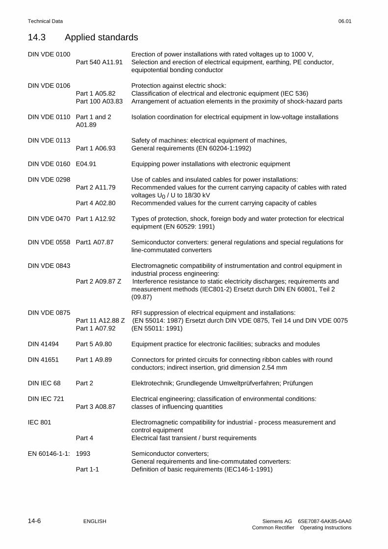
Technical Data 06.01
14-6 ENGLISH Siemens AG 6SE7087-6AK85-0AA0Common Rectifier Operating Instructions
14.3 Applied standards
DIN VDE 0100 Erection of power installations with rated voltages up to 1000 V,Part 540 A11.91 Selection and erection of electrical equipment, earthing, PE conductor,
equipotential bonding conductor
DIN VDE 0106 Protection against electric shock:Part 1 A05.82 Classification of electrical and electronic equipment (IEC 536)Part 100 A03.83 Arrangement of actuation elements in the proximity of shock-hazard parts
DIN VDE 0110 Part 1 and 2A01.89
Isolation coordination for electrical equipment in low-voltage installations
DIN VDE 0113 Safety of machines: electrical equipment of machines,Part 1 A06.93 General requirements (EN 60204-1:1992)
DIN VDE 0160 E04.91 Equipping power installations with electronic equipment
DIN VDE 0298 Use of cables and insulated cables for power installations:Part 2 A11.79 Recommended values for the current carrying capacity of cables with rated
voltages U0 / U to 18/30 kVPart 4 A02.80 Recommended values for the current carrying capacity of cables
DIN VDE 0470 Part 1 A12.92 Types of protection, shock, foreign body and water protection for electricalequipment (EN 60529: 1991)
DIN VDE 0558 Part1 A07.87 Semiconductor converters: general regulations and special regulations forline-commutated converters
DIN VDE 0843 Electromagnetic compatibility of instrumentation and control equipment inindustrial process engineering:
Part 2 A09.87 Z Interference resistance to static electricity discharges; requirements andmeasurement methods (IEC801-2) Ersetzt durch DIN EN 60801, Teil 2(09.87)
DIN VDE 0875 RFI suppression of electrical equipment and installations:Part 11 A12.88 Z (EN 55014: 1987) Ersetzt durch DIN VDE 0875, Teil 14 und DIN VDE 0075Part 1 A07.92 (EN 55011: 1991)
DIN 41494 Part 5 A9.80 Equipment practice for electronic facilities; subracks and modules
DIN 41651 Part 1 A9.89 Connectors for printed circuits for connecting ribbon cables with roundconductors; indirect insertion, grid dimension 2.54 mm
DIN IEC 68 Part 2 Elektrotechnik; Grundlegende Umweltprüfverfahren; Prüfungen
DIN IEC 721 Electrical engineering; classification of environmental conditions:Part 3 A08.87 classes of influencing quantities
IEC 801 Electromagnetic compatibility for industrial - process measurement andcontrol equipment
Part 4 Electrical fast transient / burst requirements
EN 60146-1-1: 1993 Semiconductor converters;General requirements and line-commutated converters:
Part 1-1 Definition of basic requirements (IEC146-1-1991)

06.01 Technical Data
Siemens AG 6SE7087-6AK85-0AA0 ENGLISH 14-7Common Rectifier Operating Instructions
Sources:
DIN standards and foreign standards: Beuth-Verlag GmbHBurggrafenstraße 610787 Berlin
DIN VDE regulations: VDE-AuslieferungsstelleMerianstraße 2963069 Offenbach

Technical Data 06.01
14-8 ENGLISH Siemens AG 6SE7087-6AK85-0AA0Common Rectifier Operating Instructions

SIMOVISENGLISHDisk 1+2
SIMOVISDEUTSCHDisk 1+2

06.01
Siemens AGElektronikwerk WienPostfach 83, A-1211 Wien
© Siemens AG, 1994Änderungen vorbehaltenSubject to change without notice
Siemens Aktiengesellschaft Bestell-Nr./Order No.: 6SE7087-6AK85-0AA0
Printed in Austria
Bisher sind folgende Ausgaben erschienen:The following versions have appeared so far:
AusgabeVersion
SachnummerPart number
A C98130-A1235-A3-01-47
B C98130-A1235-A3-02-47
C C98130-A1235-A3-03-7447
D C98130-A1235-A3-04-7447
E C98130-A1235-A3-05-7447
F C98130-A1235-A3-06-7447
Ausgabe F besteht aus folgenden KapitelnVersion F consists of the following chapters
Kapitel Seiten Chapter Pages AusgabedatumDate of Edition
0 Allgemeines 12 0 General 12 06.01
1 Beschreibung 2 1 Description 2 06.01
2 Transportieren, Auspacken,Montieren
4 2 Transport, unpacking,assembly
4 06.01
3 Anschließen 30 3 Connection 30 06.01
4 Inbetriebsetzen 74 4 Start-Up 74 06.01
5 Parameterliste 42 5 Parameter List 42 06.01
6 Bedienen 4 6 Operator control 4 06.01
7 Störungen und Warnungen 12 7 Fault and Alarm Messages 10 06.01
8 Wartung 10 8 Maintenance 10 06.01
9 Optionen 8 9 Options 8 06.01
10 Ersatzteile 4 10 Spare parts 4 06.01
11 Leerkapitel — 11 Blank — —
12 Logbuch 12 12 Logbook 12 06.01
13 Umweltverträglichkeit 2 13 Environmental compatibility 2 06.01
14 Technische Daten 8 14 Technical data 8 06.01