Embed Size (px)
Citation preview
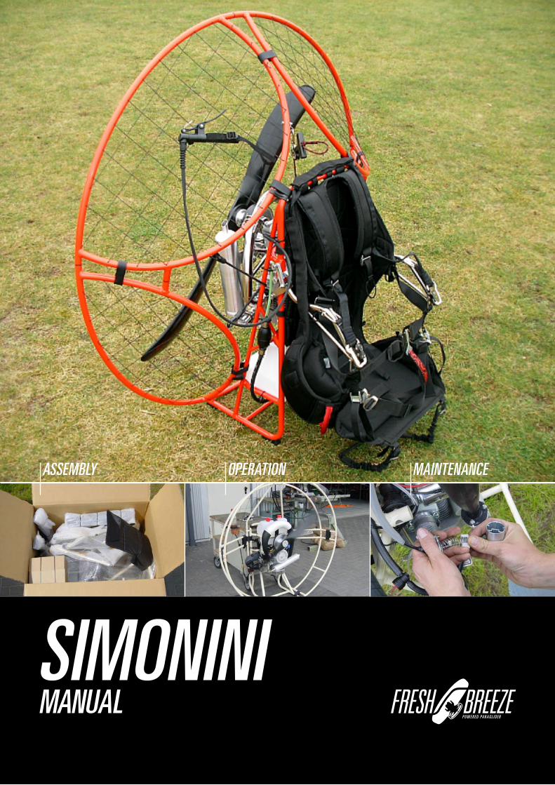
ASSEMBLY OPERATION MAINTENANCE
SIMONINIMANUAL

�
SIMONINITABLE OF CONTENTS
MANUAL
ASSEMBLY OF THE MOTOR 03
TECHNICAL DATES 06
GAY AND OIL 07
CARBURETTOR
AND INTAKESILENCER
08
WALBRO WB 37 DIAPHRAGM CARBURETTOR 11
ENGINE
12
GEARBOX 15
PROPELLER 17
ELECTRIC Standart 19
POWER IGNITION SYSTEM
20
EXHAUST
21
THROTTLE RESPECT
23
THROTTLE AIRBOSS
24
HARNESS
25
WINGMAN CB
26
PRE-FLIGHT CHECK
32
CHECKLIST
40
SAFETY ADVISE
41
43
WINGMAN CBi
28
34
SportiX 122
ELECTRIC Digital

3
SIMONINIMANUAL
ASSEMBLY OF THE MOTOR
Open the pagage with care. Do not use long knife. Parts inside the carton could be damaged.
Check the parts and proof for completeness.
Put the left and the right cages together.
Fix the cage to the frame.

4
SIMONINIMANUAL
ASSEMBLY OF THE MOTOR
Press the cage into the black clip.
Secure the cage with the Velcro to the frame.
All 4 parts of the cage should be secured.
The lowest velcro is sliped through the rails.

5
SIMONINIMANUAL
ASSEMBLY OF THE MOTOR
The backstuffing will fixed also with velcro. The upper and lower ends from backstuffing turn arround the upper and lower rope.
In case that you have a shellform-backstuffing fix it on the left and rigth side.
Most maintainance you can make by yourself with the original tools.
Contents:• Hexagon 4mm• Hexagon 5mm• T-Hexagon 6mm and 12mm• Wrench 8/10mm• Wrench for sparking-plug and screw driver
The Shellform-backstuffing prevent that the motor will turn to cause from torc.

6
SIMONINIMANUAL
TECHNICAL DATES
Motor Simonini 200ccmType 2-stroke, 1 cylinderPower 15,5 kWCooling AirStarter Manual / E-StarterCarburettor Bing 84, 32mmExhaust ResonatorPropeller 2-BladeDiameter 44“- 48“ (110 - 122 cm)Weight from 54 lbTank 10 LiterMax. Take of weight 308 lb / 140 kg (44“ Prop.) 353 lb / 160 kg (48“ Prop.)
Next dates are depeNd from:Weather, altitude, pilots Weight, glider aNd size as Well as atmospheriC humity:
Consumtion arround 3l/hMax. airbone time up to 3 hRPM 0 - 6350 u/minStaticthrust up to 155 lb (70 kg)Climbrate up to 2,5m/sec.
result from throttleleVer-positioN, flight-leVel, glider aNd size aNd pilotsWeight for the CoNsumtioN:
Little throttle less consumtionBig throttle high consumtionLow flightlevel less consumtionHigh flightlevel high consumtionSmall glider high consumtion high speedBig glider less consumtion slow speedLeightweight pilot less consumtion slow speedHeavyweight pilot high consumtion high speed

7
SIMONINIMANUAL
GAY AND OIL
The motor will delivered with two lid´s. The first is for flight with a small hole. The second lid is closed for transport. If you try to fly with the closed one the motor will have a ”in flight shut down” after a while. It´s will establish inside the tank a vacuum. The carburettor get fuel from tank through gravity.
The closed lid create inside the fueltank negative or positive pressure. This can deform the fueltank. Before you start the engine check the fueltank.
The fuel comes from tank through this filter. Check before flight.
importaNt iNformatioN
The fuel should have 95 octan or 100 LL. The best oil is Castrol 2T. Mix 2 % in additional to the fuel
No „breaking in“ method is to apply.
This picture demonstrate a closed petroltap.

8
SIMONINIMANUAL
CARBURETTOR AND INTAKESILENCER
The airbox you must fix with the two rubberlines toward the cgae and frame. Check also the clamps.
In some flyingareas it´s necessary to use such a airfilter. Use only a original parts.Otherwise you risk to loose power.
hoW i ChaNge the Needle?
Open the lid with the two screws and pull out all parts which are hanging on the cable.
Airboxatachment on carburettor WB 37

9
SIMONINIMANUAL
CARBURETTOR AND INTAKESILENCER
Press the spring togehter and loose the cable from slider. Now you hold slider and lid apart in your hand. The needle is now loose inside the slider. At our factory we installed the 6L1 in the second position from top.
Here you see succsession from:Lid/spring/giude piece/needle with ring/slider
Why i should ChaNge the maiN Jet?
Each motor will checked and testet before he leave our facto-ry. During this time we find the suitable jet. Nevertheless the motor is running bad at your first trial. At full throttle the motor runs rough (rpm less than 6150 1/min).
the reasoN is:
Other metrologic conditions, higher altitude, more humity, higher temperatur. Normally the main jet is 165. Replace this into a smaller one (160).
hoW to ChaNge the maiNJet ?
Press the bow back. With the 8 mm wrench screw out the jet.
atteNtioN:
Do not loose the small red filter.

10
SIMONINIMANUAL
CARBURETTOR AND INTAKESILENCER
Overfloating Carburettor. Fuel comes out of the two small tubes. The two swimmer regulate the niveau inside the carb. To reduce the quantity in the carb bend the little tongue ca-reful.
If you hold the carb up side down, the swimmerforc is not par-allel to the carburettorcase. If the carb overfloat while using the motor the forc should look a little bit more upward.
Before you start the cold motor press down the choke. Start the motor and after a few seconds release the choke.
The big screw regulate the idlerunning.Turning right-high rpm. Turning left lower rpm. The idlespeed should round about 240 1/min. The smaller screw is responsible for fuelmixture in idle. Turning right-rich. Turning left-lean
11
SIMONINIMANUAL
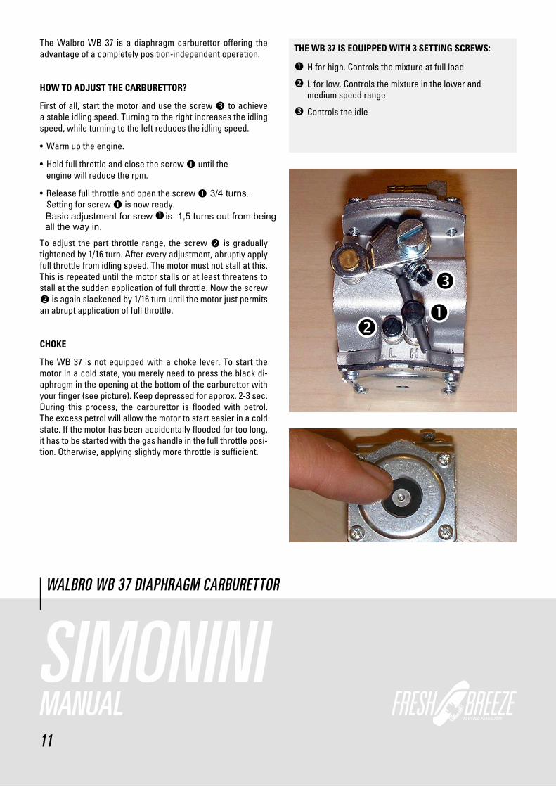
The Walbro WB 37 is a diaphragm carburettor offering the advantage of a completely position-independent operation.
hoW to adJust the CarBurettor?
First of all, start the motor and use the screw � to achieve a stable idling speed. Turning to the right increases the idling speed, while turning to the left reduces the idling speed.
• Warm up the engine.
• Hold full throttle and close the screw � until the engine will reduce the rpm.
• Release full throttle and open the screw � 3/4 turns.
Setting for screw � is now ready.
To adjust the part throttle range, the screw � is gradually tightened by 1/16 turn. After every adjustment, abruptly apply full throttle from idling speed. The motor must not stall at this. This is repeated until the motor stalls or at least threatens to stall at the sudden application of full throttle. Now the screw � is again slackened by 1/16 turn until the motor just permits an abrupt application of full throttle.
ChoKe
The WB 37 is not equipped with a choke lever. To start the motor in a cold state, you merely need to press the black di-aphragm in the opening at the bottom of the carburettor with your finger (see picture). Keep depressed for approx. 2-3 sec. During this process, the carburettor is flooded with petrol. The excess petrol will allow the motor to start easier in a cold state. If the motor has been accidentally flooded for too long, it has to be started with the gas handle in the full throttle posi-tion. Otherwise, applying slightly more throttle is sufficient.
WALBRO WB 37 DIAPHRAGM CARBURETTOR
the WB 37 is eQuipped With 3 settiNg sCreWs:
�H for high. Controls the mixture at full load
�L for low. Controls the mixture in the lower and medium speed range
�Controls the idle
Basic adjustment for srew is 1,5 turns out from being
all the way in.
�

1�
SIMONINIMANUAL
ENGINE
In flight the motor will become very hot. The most stressed airea are the piston and the rings. Remove the exhaust and have a look to appearenced piston with it´s rings. Test it with screwdriver. The rings should be loose inside the slot.
Dismantling thr head.
After removing the cylinder you can see the piston. Before you pull out the gudgeon pin remove the safety rings on both sides. Than press out the gudgeon pin.
An arrow looks into the direction of outlet.

13
SIMONINIMANUAL
ENGINE
hoW to CleaN the deCompressioNhole?
After many hour in service time the decompressionhole will closed with carbon. If you use bad oil it will close earlier. To reopening the hole use a 3,5mm drill. Bore from inside the cylinderwall with an angle from 45 °.
Bore until the drill looks into the outlet-channel.
To mount the cylinder you have to press the two pistonrings into the notch.
To tighten the headscrews with 14 Nm.

14
SIMONINIMANUAL
ENGINE
replaCmeNt of the starterrope:
Unsrew the starter-lid, take off the façade plus finger. The white disc should now be removed by pressing it against the tension-force.
The white disc can now be taken out of the lid.
The starter rope can be pulled out of the disc.
To give the starter-rope advanced tension one, place the rol-led up into the slot and rotate three times.

15
SIMONINIMANUAL
GEARBOX
The power-transmission of the gears happens via a Poly V Belt (730 8 PK). The transmission ratio equals 1:2,64. The num-ber of the revolution at full load equals 2200 rpm. The lifespan of the belt is aprox. 50-100 hrs. Too little tension shorthens the belt lifspan drastically.
hoW to tighteN the Belt?
Loose this Screw (6 mm allan-key).
Inside the propellerhub is an allan key-screw. Turn this with the 12 mm allan key until the tension is reached.
hoW to replaCe the Belt?
Loose maximal the tension of the belt. Now you can pull down the belt during you turn the pulley.
16
SIMONINIMANUAL
GEARBOX
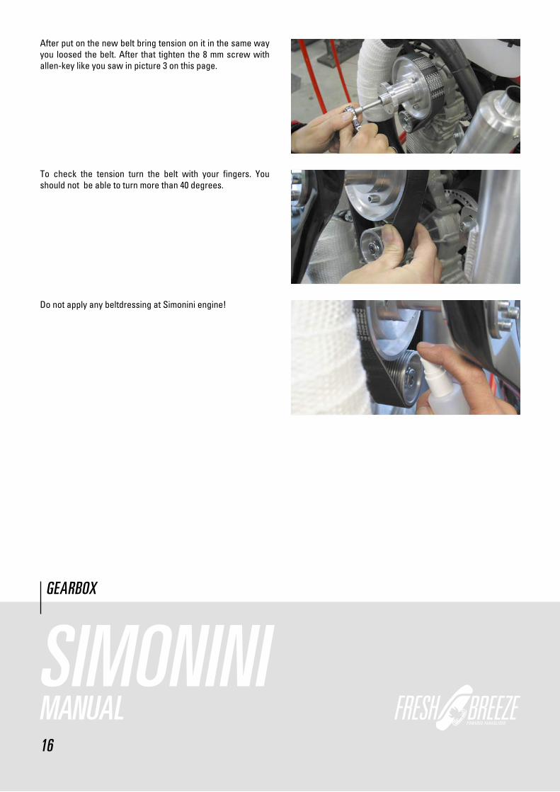
After put on the new belt bring tension on it in the same way you loosed the belt. After that tighten the 8 mm screw with allen-key like you saw in picture 3 on this page.
To check the tension turn the belt with your fingers. You should not be able to turn more than 40 degrees.
Do not apply any beltdressing at Simonini engine!

17
SIMONINIMANUAL
PROPELLER
The propeller consist of the two parts (only at 48 “) which, put together, measure up fcrom 44” to48 “ in lengh. The weight is ca 900 gram. The propeller is made of gfk or cfk, which allow for small repairs. But it is essential that after repair is accom-plish, the propeller gets balanced out again.
The propeller is fixed onto the hub with 6 screws. Tighten the propeller, use 12 Nm torc.
hoW to BalaNCed out the propeller?
The propeller has to be placed vertically onto the balancing-out equipment. If turns to one side, then drill a 3,5 mm hole into the lighter half of the propeller.
Then fill only as much resign into this hole until the propeller does not want to turn to one side only.

18
SIMONINIMANUAL
PROPELLER
Likewise proceed as above in the horizontal position.
atteNtioN:
aN imBallaNCed propeller Created uNNesseCary ViBratioN iN the eNgiNe aNd CaN destroy maNy of it´s CompoNeNts.
reQuired materials for repairs aNd BalaNCiNg-out!
The propeller balancing-out-resing with hardener, syringe and a stored shaft for a free turning of the propellerblades.
What do i reQuire for repairiNg the propeller.
Fiberglas-spatula and abrasive paper.
Here now an example when a propellerblade must not be re-paired again. If the damage is to large,then repair are dan-gerous. The repairs sopt has not enough grip and may fall off whern the propeller turns at high revolution. Danger of acci-dent is thus programmed.

19
SIMONINIMANUAL
ELECTRIC
E-Box
1.2.3.4.
plug
E-starter
altinatorcoil
start switch
ground
Engine ground
ignitioncoil
altinatorcoil
red/whiteyellow/white
red/black
cabelharness
blue
plug plug
E-starter-m
otor
+-
stop startbutton
plug Akku 16,8V
11/2008Wiring diagram „standard“ ignition ( E-Starter )„Simonini“
engine ground
12 Volt connector

�0
SIMONINIMANUAL
ELECTRIC
E-Boxdigital
1.2.3.
plug
E-starterstart switchground
Akku 16,8V
12 Volt16,8 Volt
plug 1.
2.
PVL CDI Box
plug
engine ground
startor
PVL ignitioncoil
white
red
E-starter-motor
+-
cabelharness
plug plug
stop startbutton
big
plug
5 ca
bles
killswitch
smal
l plu
g 2
cab
les
Wiring diagram „digital“ ignition ( E-Starter ) 11/2008„Simonini“
engine ground12 Volt connector16,8 Volt connector

�1
SIMONINIMANUAL
POWER IGNITION SYSTEM
The engine is equiped with a powerful and service free igni-tion system. It consist of the components: stator, loading-coil of the ignition, generator coil for the supply of electricity and rotor. To be able to work on the coils, the following should be taken care off.
Remove the complete ignitionbox including the lid of the star-ter. Now the rotor with the starter-pot is visible which is held into place by it´s central screw.
Once the central screw has been removed, the rotor can then be pulled off via a puller.Because the rotor has to be in a spe-cific position to the crankshaft, the rotor with a suspension-disc on the crankshaft is preordained.
To find the right position of point of ignition look to these pic-ture.

Setting of the ignition time for the digital ignition.The rotor of the digital ignition owns no disc feather. The right ignition time is found about the positioning of the rotor.
The upper dead centre of the piston must be determined. With the help of a measuring clock this succeeds very exactly.Afterwards put the rotor on the crankshaft .
The recess in the rotor is placed at the beginning of the pick up. See the black line.
22
SIMONINIMANUAL
POWER IGNITION SYSTEM
23
SIMONINIMANUAL
EXHAUST
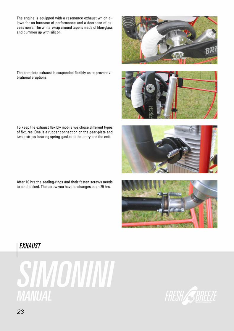
The engine is equipped with a resonance exhaust which al-lows for an increase of performance and a decrease of ex-cess noise. The white wrap around tape is made of fiberglass and gummen up with silicon.
The complete exhaust is suspended flexibly as to prevent vi-brational eruptions.
To keep the exhaust flexibly mobile we chose different types of fixtures. One is a rubber connection on the gear-plate and two a stress-bearing spring-gasket at the entry and the exit.
After 10 hrs the sealing-rings and their fasten screws needs to be checked. The screw you have to changes each 25 hrs.

24
SIMONINIMANUAL
THROTTLE RESPECT
The throttle is taken according to the building kind into the right or left hand. The strap has a variable seize change. Be-fore start the strap should be attracted firmly.
The Respect-thorttle-lever has in each case a switch at the tube. The one is for the starting the engine.
The other one for killing the engine.
The thottle has also a travelling locking. After reaching the desired hight of flight, the throttle can be fixed via the clasp-lever. Since long holt of the throttle is hard in hand, the thrott-le can be placed in position onto the legs. The hand are now free for other things.

25
SIMONINIMANUAL
THROTTLE AIRBOSS
The Airboss throttle-lever has also a button for killing the en-gine and where approbiate about one for starting the engine, if an electric starter is available.
First the throttle is taken into the hand ...
... after that the steering line and at last the A-riser are gras-ped.
This picture clarifies the handling of the riser and the throttle during the start.
26
SIMONINIMANUAL
HARNESS
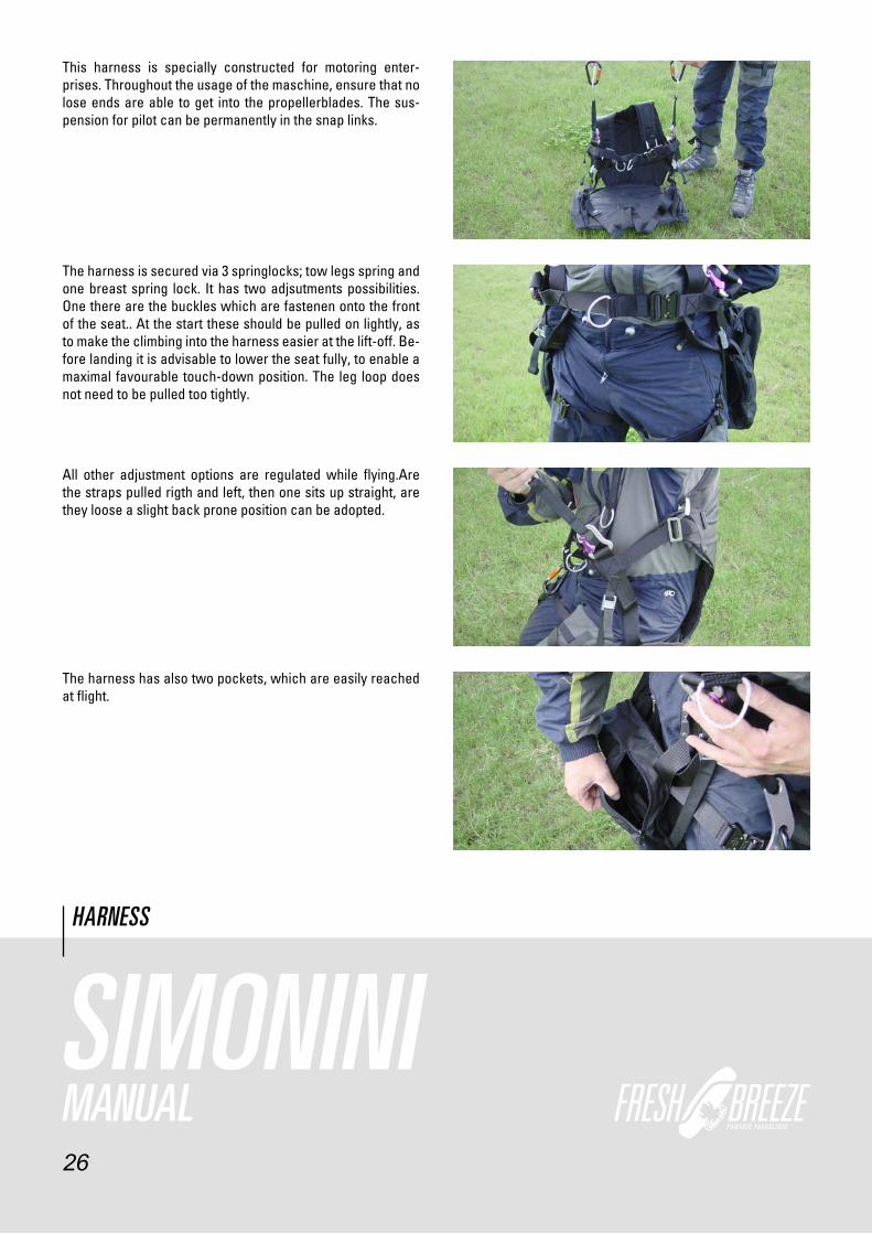
This harness is specially constructed for motoring enter-prises. Throughout the usage of the maschine, ensure that no lose ends are able to get into the propellerblades. The sus-pension for pilot can be permanently in the snap links.
The harness is secured via 3 springlocks; tow legs spring and one breast spring lock. It has two adjsutments possibilities. One there are the buckles which are fastenen onto the front of the seat.. At the start these should be pulled on lightly, as to make the climbing into the harness easier at the lift-off. Be-fore landing it is advisable to lower the seat fully, to enable a maximal favourable touch-down position. The leg loop does not need to be pulled too tightly.
The harness has also two pockets, which are easily reached at flight.
All other adjustment options are regulated while flying.Are the straps pulled rigth and left, then one sits up straight, are they loose a slight back prone position can be adopted.

27
SIMONINIMANUAL
HARNESS
Now one kneels in front of the engines and pulls the carrying straps over the shoulders.
Thereafter the pilotsuspension has to be hang into the drop-ping device of the engine. Usally the hind most hole is used for this. The dropping device should be activated at pending danger, for example at a water landing, fire at high altitude or a tree touchdown. The activation occurs when the two strings of the dropping device are pulled outwards. Because the engine is now not hanging over the suspension of the chu-te anymore,the pilot will be in a brought into a strong reclining position. Thus the engine can now slide easily over the shoul-ders. The landing proceeds from now on without the engine.

28
SIMONINIMANUAL
HARNESS
Now one get up with the whole engine and goes to the glider. The glider will then be hang into the springlocks for the pilots suspension.
After all has been done, the throttle and the break-loop had to be taken into the hand. The engine will now be started and the starting run can begin.
resCue suspeNsioN
The picture shows an example of how to fasten the recuede-vice using the V-line. The rescuedevice should be connect with the pilot suspension using the V-line. So it´s an optimal landing position in case of a possible release. The rescue-device should not be hung in the harness using the spring hooks,because of supine in rescue release.

29
SIMONINIMANUAL
WINGMAN CB
... and secure with the quickpins.
At next insert the cb bars into the frame ...
This picture show´s the attached harness.
hoW to fasteN the harNess WiNgmaN CB
Attach the harness with the velcro on the frame.

30
SIMONINIMANUAL
WINGMAN CB
The lateral and adjustable belt´s from the harnessgoes outside the cb bar´s.
The rear pilotsuspension must fixed in the metal-eyelet.
The rear pilotsuspension is adjsutable. For basic position pull the loop until the carabiner. Heavy pilots should open and light weight pilots should close the belt.
Here you must fix the carringsstraps from harnessto the frame.

31
SIMONINIMANUAL
WINGMAN CB
The glider should fixed into this carabiner.

New features at the Wingman Cbi (integrated rescue)
At the Wingman Cbi the rescue is intergated.
As you can see the Vcord runs
around the pilot from behind.
At the Wingman Cbi the rescue is intergated.
The V cord is led to the carabines
from behind and fixed with the
Velcro loops.
The neoprene outer container
32
holds the rescue system,
which is fitted with zipper onto the wingman.
The V cord is runs behind the Pilot.

Wingman CBi
The carrying belts go
through the back
of the wingman.
SIMONINIMANUAL
WINGMAN CBi
33
3�
MONSTERHANDBUCH
WINGMAN CB

SportiX 122
Schnappmatic
The glider and harness can be mounted in various positions on the flexible
push bars. This adjustment is necessary to guarantee the most comfortable
seat position to all the different pilots weights.
The prefigured factor settings of the harness seat is in position number
2. (75 kg - 85 kg)
Heavy Pilots should choose the position 1 for the wing and/or the position
3 for the harness.
34
SportiX 122
MANUAL
For the lightweight pilots it is necessar to configure the position
3 for wing and position 1for the harness

SportiX 122
SportiX 122
MANUAL
The U-shackle must secured with these rings.
These rings must guided through the shackle to be safe.
Important:
35

The harness is attached with velcro on the upper bar of the back-frame
(as in the shown in the picture)
The flexible push bars are fixed with quickpins at the frame.
At first you attached the lower quickpin and then the upper one.
The carrying straps will be mounted on the backframe
(as again shown in the picture)
36
SportiX 122
MANUAL

The integrated system rescue gives you most possible comfort. Also build in is an extra
storage container on the oppositie side of the rescue system.
Very important is to transfer the V-line (as shown on the picture)
The rescue-line splits to the right and left side of the carrying straps,
Tunnel
Tunnel
37
SportiX 122
MANUAL
on the outside of the the push-rod.
Starting from the push rod the V-line runs upwards to the shoulder.
where it is fastened with velcro.
The end of the V-line is mounted in the carabiner

The extra seat foam can help to adjust the heigt of the seat. It is
also fastened with velcro on the very front, -and on the backside with two velcros.
The cage has to be secured on the right side (in flight position) with
the help of the extra rubber strap. If your engine is equipped with
The starter rope is fastened into the right cage part.
Start the engine only on your back.
38
MANUAL
e-starter rubbercord isn`t neccessary

Seat position in flight
Landing position
After the start it is recommended to use the supine, to slip
into the harness very easy and to take end flight position.
39
SportiX 122
MANUAL

40
SIMONINIMANUAL
THE FOLLOWING POINTS SHOULD BE CARRIED OUT BEFORE EVERY START!
01. CHECK ALL PARTS FOR TIGHTNESS, CHECK ALL FASTENERS!02. VISUAL INSPECTION OF CAGE AND FRAME FOR FRACTURES!03. PROPELLER HUB WITHOUT CLEARANCE?04. EXHAUST SPRINGS OK?05. EXAMINATION OF EXHAUST RUBBER ELEMENTS!06. PETROL FILTER NOT SOILED?07. MOTOR, CARBURETTOR AND TANK LEAK-PROOF?08. SUFFICIENT SUPPLY OF PETROL?09. PILOT SUSPENSION UNDAMAGED?10. CANOPY UNDAMAGED?11. GAS LEVER POSITION?12. TRAVELLING LOCK RELEASED?13. FUEL TAP OPEN? 14. VENTILATED TANK LID ON TANK?15. PROPELLER CLEAR – START MOTOR!16. CARRY OUT A TEST AT FULL THROTTLE!17. TEST THE OFF-SWITCH FUNCTION18. PILOT PROPERLY HOOKED IN?19. WIND DIRECTION AND WIND FORCE?
EVERYTHING O.K.? CLEAR FOR TAKE-OFF!
PRE-FLIGHT CHECK
20. TAKE-OFF STRETCH CLEAR?FUEL TANK IS FIXED AND THE GAP BETWEEN EXHAUST-FUEL TANK ASSURED
21.

41
SIMONINIMANUAL
CHECKLIST
CHECK BEFORE EACH FLIGHT
ü CAGE SECURED ON THE FRAMEü CAGE IN GOOD SHAPEü PROPELLER-CLEARANCEü PROPELLER WITHOUT FREE SPACEü PROPELLER WITHOUT DAMAGEü BELT AND TENSION ENOUGHü KILLSWITCH O.K.ü FUEL MIN.98 OCTANE OR HIGHERü FUEL TANK LEAKYü PILOT SUSPENSION AND STRAP WITHOUT STRESSMARKSü SPARKING PLUG AND WIRE WELL FIXEDü TANK-LID WITH SMALL HOLE ON THE TANKü PROOF GLIDER,LINES AND RISER FOR STRESSMARKS OR DAMAGE´S.ü INTAKESILENCER AND IT´S FIRMNESSü FULL RPM MIN 6000 U/MIN
CHECK ALL 10 HOURS
ü FUEL FILTER
ü CLEAN THE CARBCHAMBER
ü BELT
ü EXHAUST INCL. THE SELAINGRINGS AND THE SCREWS.
ü ALL CONNECTION FROM THE WIRES
ü EXHAUSTCONNECTORSCREWS
ü FUNKTION FROM CARRINGSTRAPS
CHECK ALL 50 HOURS
ü REPLACE THE BELT
ü METAL-WIRE FROM THROTTLE
ü REPLACE THE SPARKING PLUG AND THE CONNECTOR
ü REPLACE ALL RUBBERjOINT FROM EXHAUSTSYSTEM
ü REPLACE THE SEALINGRINGS AND THE SCREWSü CHECK ALL SCREWS
ü REPLACE CLAMPSCREW (8 X 40 MM) FORM PROEPLLERHUB
ü ALL WIRES WITH IT´S CONNECTIONS
ü TANK
ü REPLACE STARTERFINGER

42
SIMONINIMANUAL
CHECKLIST
ü REPLACE NEEDLE AND NEEDLEjET
ü REPLACE INTAKETUBE (SPIRAL)
ü PROPELLERBALANCE
CHECK ALL 100 HOUS
ü CLEANING THE DECOMPRESSIONHOLE INSIDE THE CYLINDER
ü PISTONRINGS
ü REPLACE PROPELLERBEARINGS
ü REPLACE INTAKE DIAPHRAGM
ü REPLACE KARABINER FROM PILOTSUSPNSION
ü REPLACE SLIDER FROM CARB
CHECK ALL 300 HOUSü THE ENGINE AND HIS COMPONENTS SHOULD SEND TO THE MANUFACTURING FOR GENERAL MAINTENANCE
GLIDER THE GLIDER SHOULD BE CHECKED ALL 2 YEARS.SEND TO THE MANUFACTURER
MOTOR
THE ENGINE SHOULD BE CHECKED EACH YEAR ALIKE HOW MUCH HOURS IT´S USED
Without these CheCK´s No WarreNty or other Claims!
please use oNly fresh Breeze geNuiNe sparparts.this Will taKeN possessioN all safety aNd stiffNess WhiCh is reQuiered from dulV.
!
!
Change the carabiner from the pilotsuspension each 100 hü CHECK ALL150 HOUSü
Replace needlebaring piston/rod #12110 S

43
SIMONINIMANUAL
SAFETY ADVICE
BE SURE TO FOLLOW THIS SAFETY ADVICE EVERY TIME YOU USE FRESH BREEZE MOTORS !
• USE YOUR ENGINE CAREFULLY. DISREGARDING ANY SAFETY ADVICES AND INCAUTIOUS BEHAVIOUR MAY LEAD TO SERIOUS INjURIES.
• NEVER COME CLOSE OR GRAP INTO THE SPINNING PROPELLER. HIGH RISK OF SEROIUS INjURIES.
• THE ENGINE MAY NOT BE STARTED WHEN IT IS STANDING ON THE GROUND. HIGH RISK OF SERIOUS INjURIES.
• NEVER TOUCH HOT PARTS (ENGINE, EXHAUST). HIGH RISK OF BURNING.
• Unexperienced pilot´s should have minimum 80 kg (176 lbs).Otherwise you risk a stall or twist in while of full throttle